Article

Application of Thermal Spraying Technology in Concrete Surface Ceramic-Based Coating

1
Changjiang River Scientific Research Institute, Changjiang Water Resources Commission, Wuhan 430010, China
2
Research Center of Water Engineering Safety and Disaster Prevention, Ministry of Water Resources, Wuhan 430010, China
3
School of Civil Engineering, Hubei Engineering University, Xiaogan 432000, China
*
Author to whom correspondence should be addressed.
Coatings 2024, 14(7), 885; https://doi.org/10.3390/coatings14070885 (registering DOI)
Submission received: 20 June 2024 / Revised: 12 July 2024 / Accepted: 12 July 2024 / Published: 16 July 2024
(This article belongs to the Section Ceramic Coatings and Engineering Technology)

Abstract

:
Enhancing the durability and extending the service life of concrete are crucial for promoting its sustainable development. Applying surface coatings is the primary technical method used to improve concrete durability. In this study, based on the plasma thermal spraying technology, a thermal-sprayed, ceramic-based coating was prepared on a concrete surface and evaluated using the drawing method, X-ray diffraction scanning electron microscopy with energy dispersive spectroscopy, X-ray computed tomography (X-CT), and frictional wear. Subsequently, performance tests were conducted. The test results showed that mullite powder was a suitable ceramic-based coating material. The coating had a good interfacial bonding ability with the concrete surface; moreover, the bonding site exhibited a chimeric state with an adhesion strength of 3.82 MPa. The wear rate of the coating material (0.02‰) is lower than that of the concrete matrix (0.06‰), resulting in improved surface wear resistance. SEM analysis reveals that the coating contains a considerable amount of amorphous or microcrystalline phases. The internal structure of the coating exhibits porous characteristics, with a total porosity of 10.35% and pore diameters predominantly ranging from 4 μm to 16 μm. At a distance of 80 μm from the coating site, the elements Al, O, and Si significantly contribute to the mullite components. The porous structures within the coating products are further verified using X-CT. This study offers a new possibility for ceramic coatings on hydraulic concrete.

1. Introduction

Concrete is the most widely used artificial building material, known for its low cost, good plasticity, abundant raw material sources, and strong bearing capacity. To extend the service life of building structures, it is essential to improve the appearance quality of concrete and ensure its long-term durability. Besides using appropriate mixing ratios and advanced casting technologies during the design and construction stages, surface coating protection technology offers a cost-effective and convenient solution. This technology effectively reduces the penetration of isolating media into the concrete surface, addressing issues such as seepage cracking, freeze–thaw resistance, corrosion resistance, impact and wear resistance, and enhancing appearance quality. It has gained recognition in international academic and industrial circles and is widely applied in fields such as water conservancy, railroads, bridges, marine engineering, and construction [1,2,3,4,5,6,7,8].
The main technical approach to improving the durability of concrete is to reduce the interaction between the substrate and the surrounding environment through surface coating protection technology [9]. Currently, organic coating materials are among the widely used surface coatings for concrete. Organic coating materials have a flexible form and strong hydrophobicity [10,11], and many studies have focused on these organic coatings for concrete. Shohide [12] invented asphaltic polyurethane nano-silica coatings and found adhesion strength increased with increasing nano-silica content up to 2%, while water absorption and chloride ion diffusion decreased. The coated concrete showed good durability against sulphate and chloride attacks. Qu et al. [13] studied the addition of nano-SiO2 or nano-TiO2 to the water-based organic coating and found that it can reduce the defects in the coating, effectively improve the density of the coating, further improve the carbonation and chloride resistance of the coated concrete with average improvement ranges of between 51%–74% and 24%–27%, and reduce the damage of water-based coatings caused by ultraviolet irradiation. Chi et al. [14] developed a novel epoxy coating with a cross-linkable solvent via the Diels–Alder reaction, allowing it to permeate into concrete pores up to 1.5 mm and form a strong bond when the solvent cross-links at higher temperatures. This coating not only strengthens the concrete’s mechanical strength and corrosion resistance but also has low volatile organic compound (VOC) content, making it environmentally friendly and suitable for protecting concrete. Wang et al. [15] investigated the degradation of organic coatings on concrete due to environmental stressors, focusing on the relationship between the coatings’ degradation, adhesion loss, and deteriorating protective performance. Through extensive tests and characterization methods, it was found that while UV exposure significantly altered epoxy coatings, polyurea coatings showed minor changes; however, polyurea coatings show a more pronounced decrease in chloride resistance due to a greater loss of adhesion, which underscores the importance of adhesion to the protective properties of these coatings. The studies described above demonstrate the effectiveness of organic coating materials for concrete. However, there are some limitations, such as poor fire resistance, susceptibility to deterioration, significant reduction in effectiveness at elevated temperatures, ultraviolet radiation, cracking or flaking, and difficulty in cleaning the building after failure [16].
In addition to organic coating materials, inorganic coating materials are also used on concrete surfaces. Compared to organic coating materials, inorganic coatings offer better aging resistance and lower costs. There have been numerous studies on inorganic coating materials for concrete surfaces. For instance, Franzoni et al. [17] studied the effectiveness of various inorganic materials, including ethyl silicate, sodium silicate, and nano-silica, in protecting concrete surfaces. Jia et al. [18] explored the effects of fluosilicate and sodium silicate surface treatments on the permeability of concrete. Experimental results indicated that both treatments effectively reduced permeability, with fluosilicate being more effective in the initial 28 days post-treatment and sodium silicate showing greater impact at later stages; additionally, the treatments decreased the surface layer porosity of these materials. Li et al. [19] invented a novel nano-polymer-modified cementitious coating synthesised through the incorporation of nano-SiO2 or nano-TiO2 suspensions which can effectively play filling effects, refine the large micropores in coating, and reduce its porosity while maintaining breathability function. The coating can greatly reduce the water absorption ratios and Coulomb charges of coated concrete and enhance the waterproofing and chloride resistance of coated concrete. Amer et al. [20] developed a multi-layered TBC system with GZ and YSZ using SPS to improve thermal cycling resistance. The study examined cracking after thermal exposure, revealing horizontal ceramic cracks and interface cracks related to thermal stress and TGO thickness. Amer et al. [21] studied crack formation in APS thermal barrier coatings using real-time bending and SEM. They discovered that microstructural features like pores and splats influence crack branching and deflection, which can enhance coating toughness and durability. While these findings highlight the potential of inorganic coatings for concrete protection, challenges remain in improving crack resistance and bonding capabilities.
Thermal spraying technology is rapidly developing as a surface-coating technology, which can compensate to some extent for the deficiencies of the coating materials mentioned above. Currently, it is not commonly implemented in cement concrete, and there are few reports on the plasma thermal spraying of protective layers on concrete surfaces. Lee et al. [22] used an arc thermal spraying method to electroplate stainless steel on the surface of reinforced concrete and coated a polymer sealing layer to protect the acid wastewater treatment tank from corrosion. Subsequently, they studied the electromagnetic shielding performance of a Zn-Al metal thermal-sprayed material on carbon black-mixed concrete. Wang et al. [23] studied the thermal spraying of sacrificial anodes for the cathodic protection of coastal reinforced concrete structures to address the problem of insufficient initial driving potential in sacrificial anodes. The research object in the abovementioned studies is reinforced concrete structures, but these studies are in the field of metal corrosion. Some researchers have used numerical simulation methods [24,25] and discovered that the contact time between the high-temperature coating and substrate during the thermal spraying process is extremely short. The time required for molten particles to spread out and solidify when they impact the substrate surface is only 0.1–1.0 μm. During the use of thermal spray coatings, there may be problems such as the gas generated during the spray process is not discharged in time, resulting in the formation of pores in the coating, and cracks in the coating may be caused by temperature changes, thermal stress, or material shrinkage. The bond strength between the coating and the substrate is insufficient and the peeling occurs. The heat transfer rate of instantaneous solidification is much lower, and the temperature increase in the substrate is extremely limited, which verifies the feasibility of the thermal spraying technology on concrete surfaces.
Based on the current research status mentioned above, it is evident that there is almost no research on inorganic coatings, especially ceramic coatings, used for protecting concrete surfaces. There is also a significant gap in knowledge regarding their construction processes and optimal material selection. Ensuring strong adhesion between ceramic coatings and concrete substrates is challenging due to differences in their physical and chemical properties. Concrete has poor thermal conductivity; therefore, the number of coating droplets is small, and the heat generated by thermal spraying is limited. Since the process involves instantaneous high temperatures, the impact on the matrix surface is minimal. Ceramic-based thermal spraying layer is widely used in various fields of material protection and has become one of the research hotspots; however, in the field of water conservancy and hydropower engineering, especially in concrete protection, the relevant research is still blank. To optimise the process of concrete surface coating using thermal spraying, the good bonding ability of the coating material with the substrate must be first considered, such as deformation coordination, wear resistance, and high weather resistance [26,27]. Therefore, the thermal expansion coefficient of the coating material must be similar to that of cement concrete, with a high melting point, corrosion resistance, and good stability. Selecting a proper thermal spray coating material that matches the thermal expansion coefficient of concrete can reduce the residual stresses that occur in the combination of the two and improve interface bonding and deformation coordination. The thermal expansion coefficient of the concrete matrix α is approximately 5 × 10⁻⁶/°C–10 × 10−6/°C; the coefficient of cement mortar or cement stone is higher than that of concrete [28]. The thermal expansion coefficient of mullite is 5.3 × 10⁻⁶/°C, making it more suitable to be used with concrete. Therefore, it is possible to use mullite as a thermal-sprayed layer material on a concrete surface.
This paper carried out research on the preparation and performance testing of thermal sprayed ceramic-based coatings on concrete surfaces. Based on the plasma thermal spraying technology, a thermal-sprayed, ceramic-based coating was prepared on a concrete surface. The influence of high temperature on the performance of concrete can be further reduced or even eliminated by optimising the spraying process, changing the spraying method, and reducing the duration. The appearance and phase analysis, interface bonding ability, microstructure and structure, X-ray computed tomography (X-CT) three-dimensional structure distribution, and wear resistance of mullite thermal sprayed coatings were used to assess the performance indices and laws of thermal sprayed coatings. The purpose of this study is to use plasma thermal spraying technology to single out the ceramic-based protective materials that match the cement concrete matrix and develop a highly efficient, wear-resistant, chemical corrosion-resistant, and high-temperature-resistant concrete surface protective coating technology. The study finally selected a thermal-sprayed, ceramic-based coating with a thickness ranging between 0.3 and 0.5 mm and a density between 1.1 and 1.3 g/cm3. The research results are expected to pave a new path for the future of hydraulic inorganic coatings.

2. Experimental Program

2.1. Materials

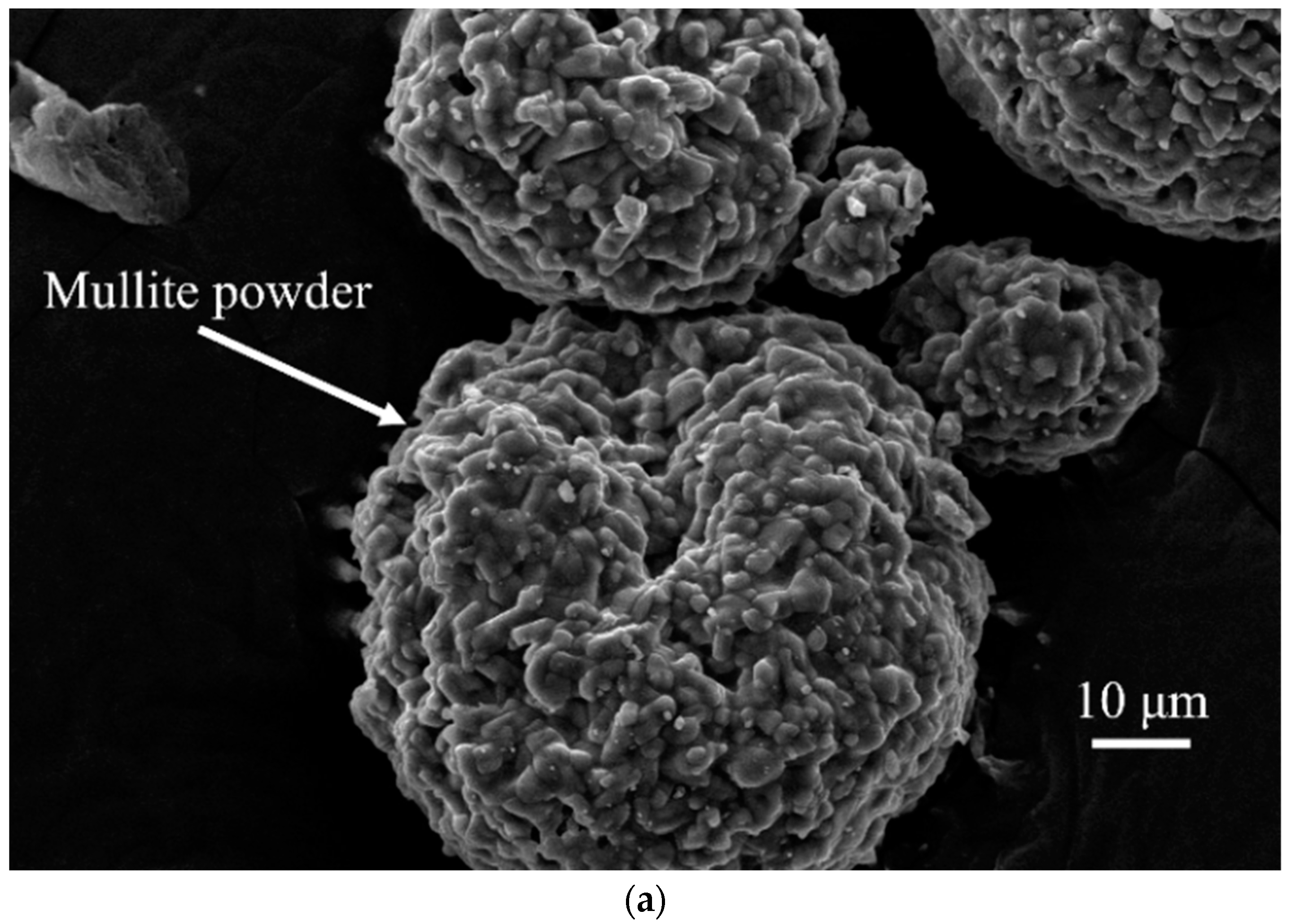
2.1.1. Coating Materials

The melting temperature of mullite powder is 1850 °C. After spray granulation, spherical particles were formed with a particle size of −160–+325 mesh. The corresponding scanning electron microscopy (SEM) image is shown in Figure 1a. The particles are hollow spheres with good fluidity and are suitable for thermal spraying transmission. The X-ray diffraction (XRD) pattern of mullite powder is shown in Figure 1b. The observed powder crystallisation effect is good, exhibiting a sharp diffraction peak shape, high symmetry, high diffraction intensity, and high purity; no other impurities are observed. At the same time, thin plate-like concrete products were used for the concrete matrix; after removing the floating ash or weakened layer, the concrete surface was also processed via ultrasonic washing and drying before use.

2.1.2. Concrete Materials

The concrete is made of moderately hot cement and Class I fly ash, and the ratio is designed by using the first-class concrete ratio, mixing 5~20 mm small stones, and mixing defoamer to eliminate air holes. The chemical composition of cement and fly ash is shown in Table 1. As can be seen, the proportion of CaO and SiO2 is the highest, followed by Al2O3, Fe2O3 MgO, and SO3; the quality ratio between CaO and SiO2 is 3.1, which is greater than 2.0. The components meet the requirements in the Chinese standard “Common Portland Cement” GB175-2020 [29]. The basic properties of cement are shown in Table 2, which also meet the requirements of the specification [29]. The basic properties of fly ash are shown in Table 3, which meet the requirements of the specification [30].

2.2. Specimen Design and Investigated Cases

2.2.1. Specimen Design

A concrete substrate of moderately hot cement and 30% Class I fly ash, with a design strength class no less than C30, was processed into a sheet-like shape of 15 mm thickness for ease of spraying operation. The concrete substrate used for surface spraying is shown in Figure 2 as a dense concrete specimen without air pockets.

2.2.2. Investigated Cases

The research in this paper mainly includes the selection and optimisation of the thermal spraying process for concrete surfaces. Based on the atmospheric plasma spraying technology, we optimised the process flow of the substrate preparation, surface pretreatment, spraying preparation, spraying process, cooling process, post-spraying treatment, etc., and preliminarily determined the parameters of the spraying process and explored the optimal process measures to improve the spraying effect and enhance the adhesion ability of the coating and its own performance.
Thermal spraying layer performance testing and evaluation. Macro and microscopic testing methods were adopted to test the interfacial bonding ability, microstructure, porosity, and internal pore distribution of the thermally sprayed layer on the concrete surface, as well as the wear resistance of the coating, so as to evaluate the performance characteristics and effect of the thermally sprayed layer on the concrete surface. The main test methods and corresponding indicators used in this paper are shown in Table 4.

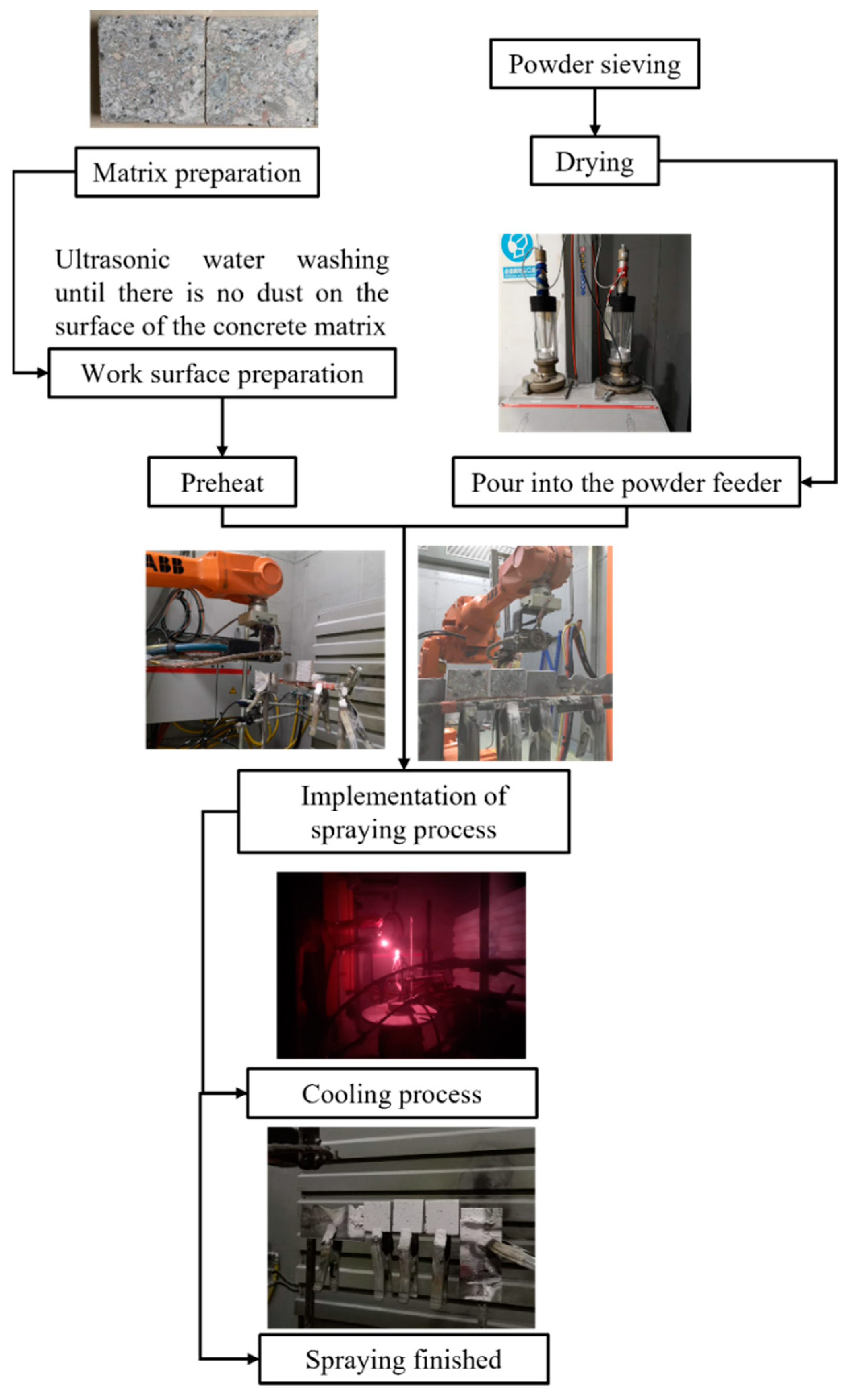
2.3. Coating Preparation Procedures

The thermal spraying test of the concrete surface was performed using atmospheric plasma thermal spraying technology (Metco, Multicoat automatic thermal spraying system) (Oerlikon Metco (US) Inc., Westbury, NY, USA) [31]. The positioning accuracy of the manipulator was 0.1 mm, the holding weight was 20 kg, the spraying power was 32 kW, the distance between the spray gun and sample surface was 150 mm, the moving speed of the spray gun was 800 mm/s, and the rotating speed of the powder feeding was 15%.
The concrete substrate is a poor conductor of heat. In order to avoid surface damage and improve the bonding quality of the coating, compressed air is used to synchronously cool the front of the substrate at an air of 3 bar. The greater the air pressure of the cooling substrate is, the better the cooling effect becomes; however, excessive air pressure will affect the spraying flame itself. Therefore, 3 bar was set as the common cooling value during spraying [32,33]. The coating thickness ranged between 0.3 and 0.5 mm after the sample naturally cooled to room temperature. Three measurements were taken and then averaged using a micrometre for thickness testing. A sealing agent was used to seal the sprayed products to reduce the inherent pores in the coating and ensure airtightness to avoid contamination by the external environment. The flow chart of the coating preparation is shown in Figure 3.

2.4. Experimental Methods

2.4.1. Mechanical Testing

Compressive Testing and Splitting Tensile Testing

Conducted in accordance with SL/T 3520-2020, “Test code for hydraulic concrete.” [34]. Cubic compressive strength and splitting tensile strength tests were conducted using standard specimens of cubes with side lengths of 150 mm.

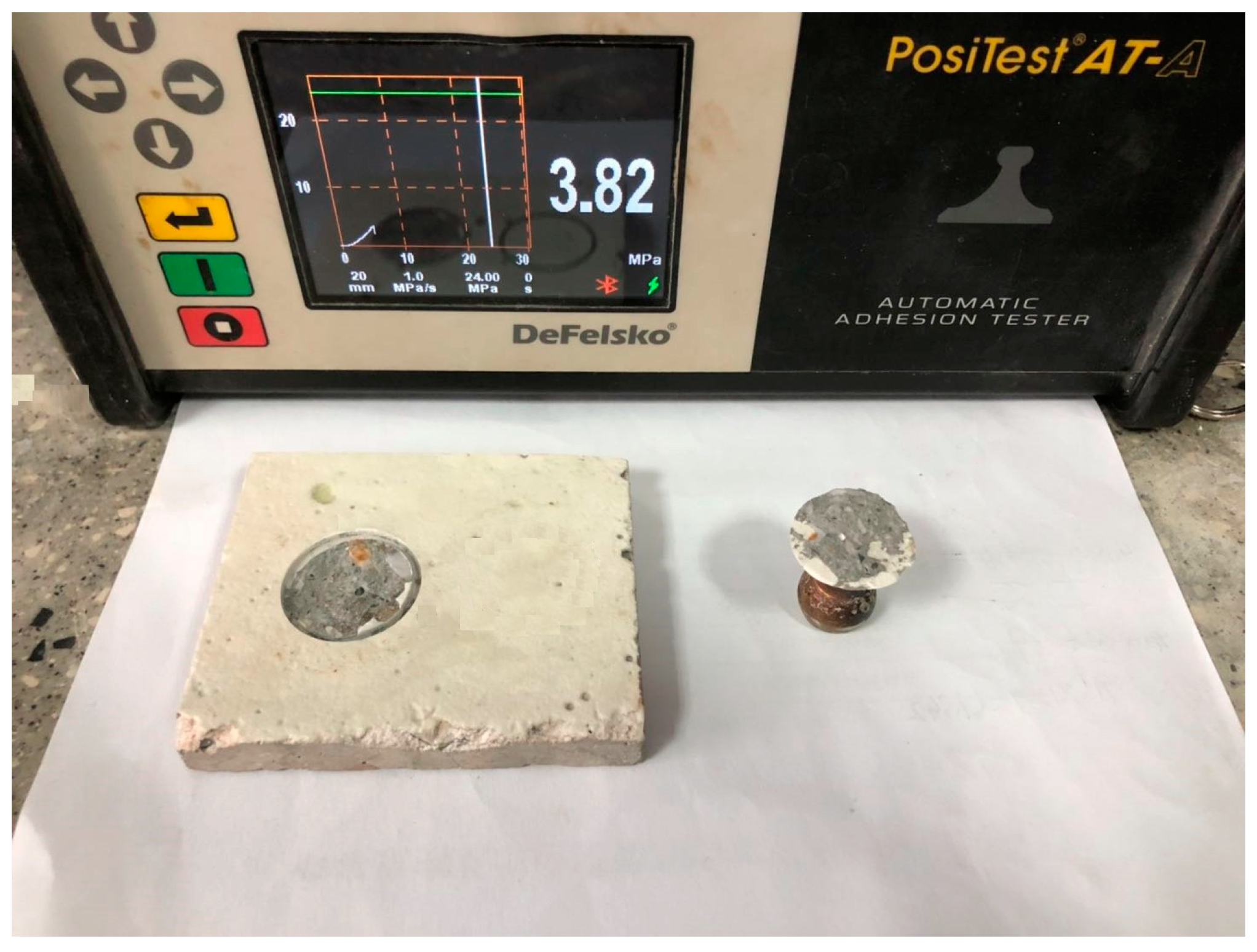
Interface Adhesion Testing

According to ASTM-D4541-2009, “Standard Test Method for Pull-Off Strength of Coatings Using Portable Adhesion Testers” [35], based on the simple and easy pull-off method, a portable adhesion tester was used to test the interfacial bonding force between the mullite coating and the concrete substrate, i.e., the adhesion force.

Wearing Testing

To determine the actual wear resistance provided by the thermal-sprayed layer, an HT-1000 high-temperature friction and wear tester (Lanzhou Huahui Instrument Technology Co., Ltd., Lanzhou, China) was used to test the friction and wear properties of the thermal-sprayed layer without the sealing treatment. Ultrasonic alcohol cleaning was performed before the test. The test temperature was maintained at 25 °C. The friction contact mode was ball contact. The applied test load was 0.2 N, the friction speed was 632 rpm, the X-axis friction radius was 3 mm, and the continuous test time was 8 min.

2.4.2. Characterization Testing

SEM-XRD Analysis

The phase composition of the coating material was determined using XRD analysis. XRD tests were carried out using a D8 Advance X-ray diffractometer (Bruker, Billerica, MA, USA). The test parameters were as follows: operating voltage of 40 kV, operating current of 40 mA, and test angle range of between 5° and 70° (2θ).

SEM-EDS Testing

The scanning electron microscopy with energy dispersive spectroscopy (SEM-EDS) micro-test method was used to observe the microstructure and interface bonding at the thermal-sprayed layer and concrete cross-section, and a semi-quantitative elemental composition analysis was carried out.

X-CT Three-Dimensional Meso-Structure Test

Using an Xradia 510 Versa high-resolution 3D X-ray microscope (ZEISS, Jena, Germany), with a highest 3D spatial resolution ≤ 0.7 μm and density resolution of 0.13 g/cm3, a three-dimensional visual reflection of the internal structure at the thermal-sprayed layer and substrate material was obtained, and the compactness, pore structure, and interface bonding were analyzed.

3. Results and Discussion

3.1. Coating Mechanical Testing

3.1.1. Interface Bonding Ability

When the surface with the sprayed material is subjected to various loads, damage usually occurs at the interface between the coating and substrate. Therefore, the interface bonding strength between the coating and substrate is a key factor that determines the overall performance of the material and an important indicator for evaluating the coating quality. Based on a simple and easy drawing method, an adhesion tester was used to test the interface bonding ability between mullite coating and concrete matrix, as shown in Figure 4. The pull-off test results of the thermally sprayed concrete surface are listed in Table 5. It can be observed that the three test results are relatively concentrated, with an average value of 3.82 MPa, which even exceeds the tensile strength of the concrete matrix itself (3.26 MPa). The fracture in the concrete after the pull-out test was uneven, indicating that the thermal-sprayed layer and matrix exhibit a good interface bonding ability. Studies have demonstrated that the coating strength and its bonding with the substrate depends on the interaction among the molten droplets as they impact the surface, which is related to its melting state [36,37]. The melting condition is good, the coating bonding strength is improved, and the overall porosity is low.

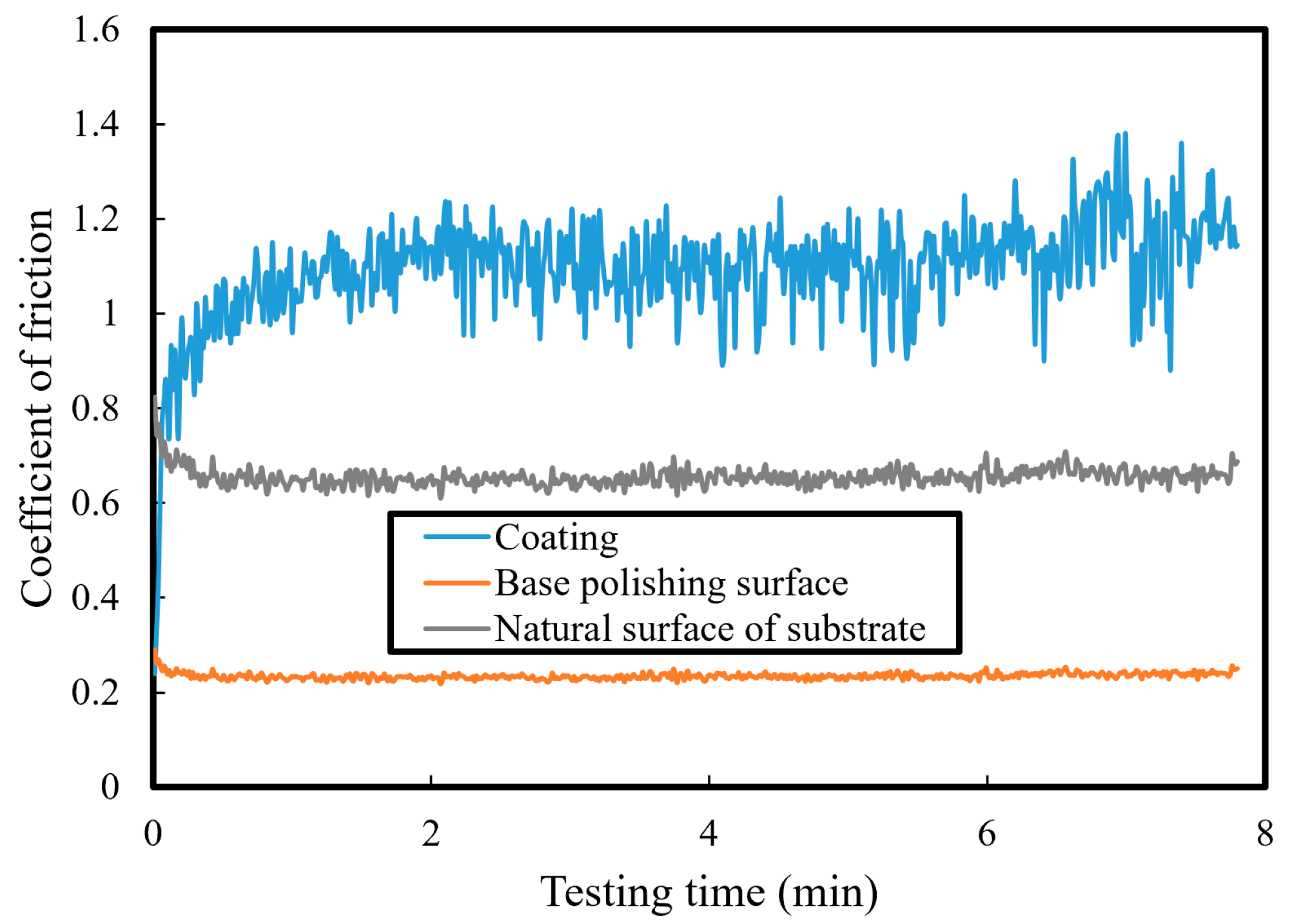
3.1.2. Coating Wear Resistance

A wear test can be used to compare the materials’ wear resistances. The wear characteristics of a coating result from a series of internal and external factors, including the wear conditions, coating chemical composition, and spraying process parameters. The wear resistance is often measured based on the amount of wear. Here, the weight loss method was used to measure the mass of the specimen before and after the friction and wear tests, based on which the wear rate was calculated. The results are shown in Table 6. The results indicate that, under these loading conditions, the wear rate of the coating material (0.02‰) is lower than that of the concrete matrix (0.06‰), indicating that the coating material has better wear resistance. Moreover, from the appearance of the surface, it can be observed that there are friction marks on the surface; however, the degree is low, and the damage is small.
The friction coefficient curves of the concrete substrate and thermal-sprayed layer are shown in Figure 5. The friction coefficient denotes the ratio of the friction force to the applied vertical load, which is related to the surface roughness and unrelated to the size of the contact area. The results indicated that the friction coefficient of the coating surface was higher than that of the substrate under this loading condition. For concrete materials, the friction coefficient of the natural surface of the processed specimen was between 0.6 and 0.8; the measured value for the polished surface was significantly reduced to 0.2–0.3. Both values decreased slightly after approximately half a minute and became relatively stable. For the coating material, the friction coefficient exhibited an upward trend within 1 min and stabilised at approximately 1.1 min after the first minute. After 6 min, the results did not decrease but there was an increasing tendency. It can be concluded that at room temperature, abrasive wear occurred in both the coating and substrate specimen, and the wear mechanism did not change during the testing period. The friction coefficient of the coating material did not decrease with time, indicating long-lasting wear resistance.

3.2. Characterization Testing

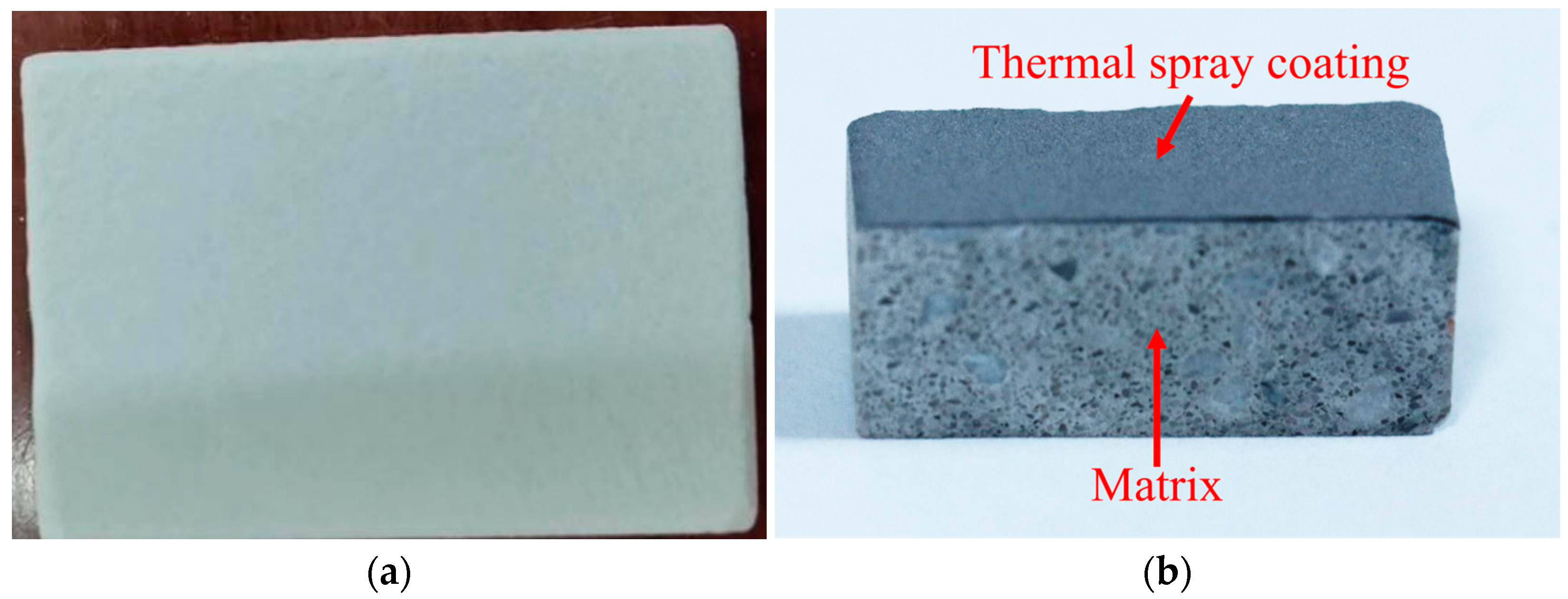
3.2.1. Appearance and Phase Analysis

The appearance of the thermally sprayed layer on the concrete surface is shown in Figure 6. The appearance of the coating is uniform, indicating that it can cover the surface of the concrete substrate integrally. The results of SEM are shown in Figure 7. The coating thickness is about 0.3–0.5 mm after being measured using a vernier calliper. As shown in the figures, the coating is paved layer by layer on the concrete surface after cooling, and there is a small amount of spherical mullite particles that are not fully melted. The XRD patterns of the coatings are shown in Figure 8. Compared with the results obtained with mullite powder, the composition of the thermal-sprayed layer did not change; however, the background noise of the spectrum was large, indicating its impurities. In the crystal state of the main phase, 2θ in the spectrum appeared at a low angle (15°–25°). The broad immersion scattering peak with a less obvious background indicates that there is an amorphous state in the coating. In addition, the dispersion characteristics in the spectrum indicate that the coating contains a considerable amount of amorphous or microcrystalline phases. Some of the crystalline mullite in the coating may originate from the crystallisation of the mullite precipitated through the high-temperature phase during the spraying process; the other part may be the non-melted residual mullite powder particles. The amorphous material in the coating is formed because the mullite powder transforms into a molten droplet after melting in the plasma melt flow, and, then, the droplet collides with the substrate instantaneously, and there is a high-temperature gradient between the two, which prevents the liquid droplets from crystallising [38].

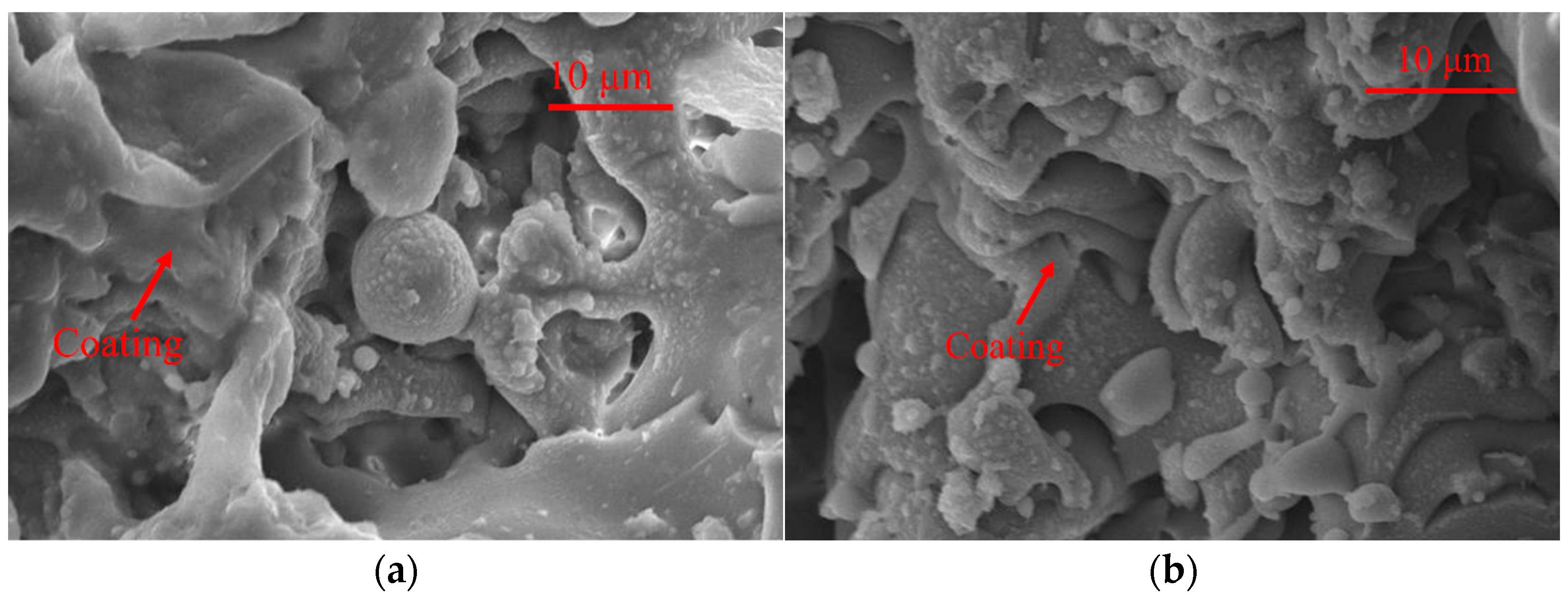
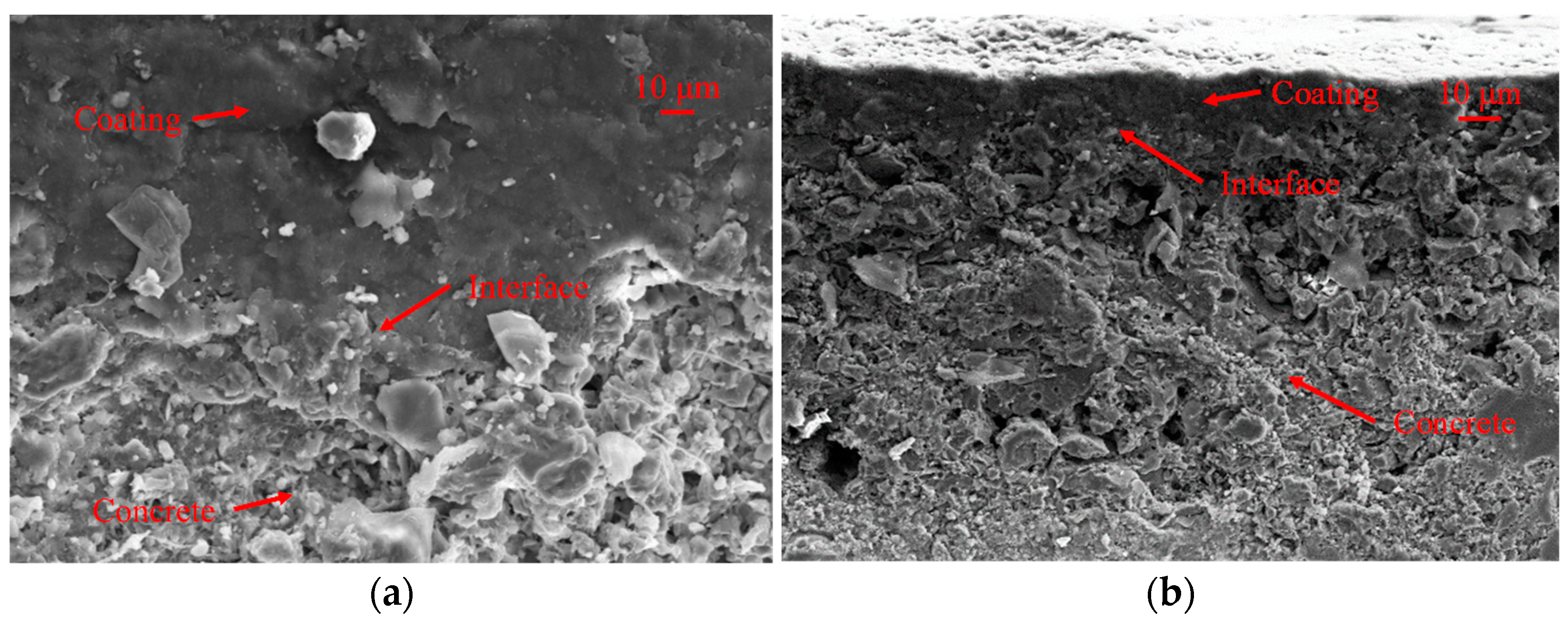
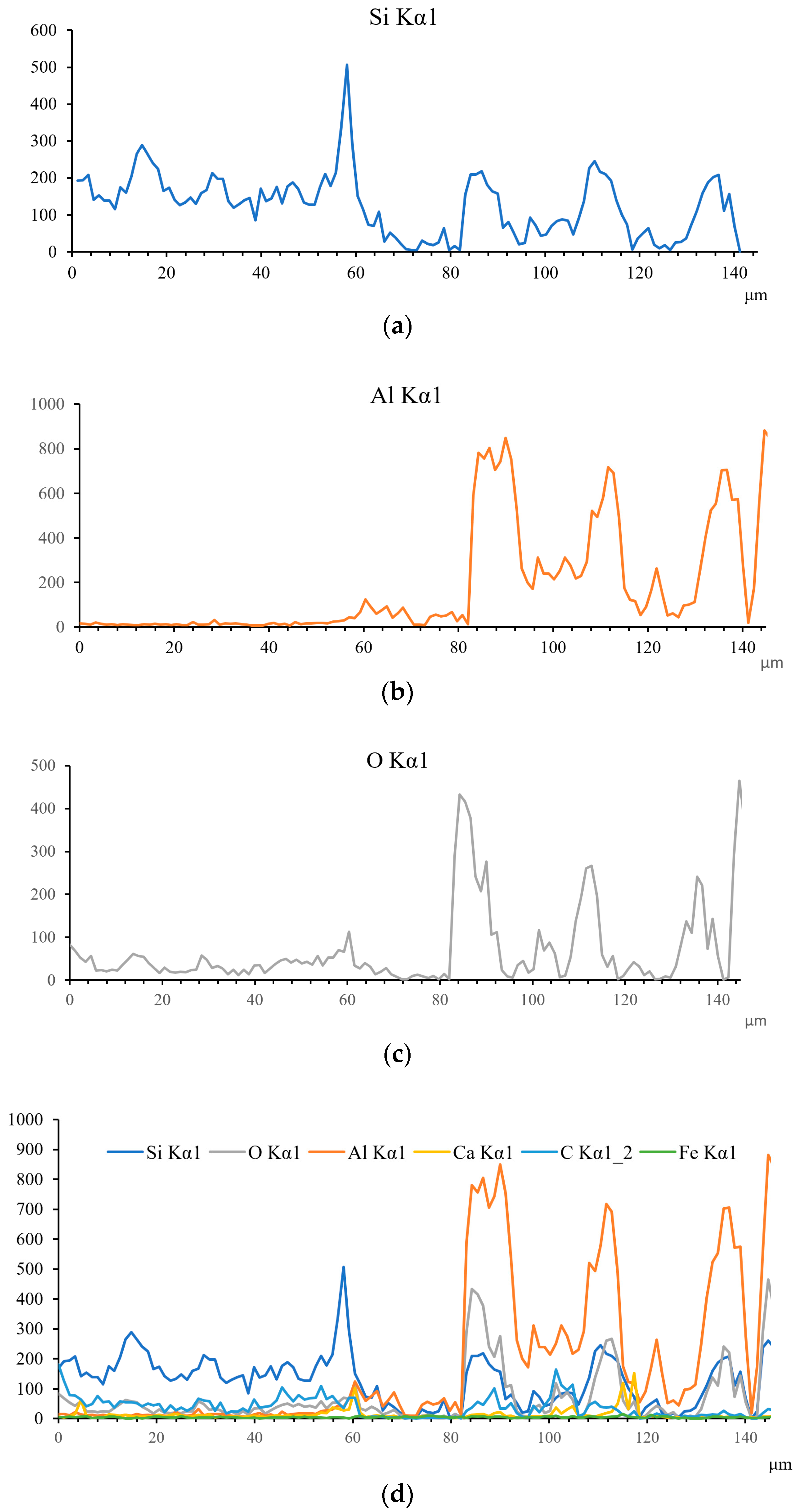
3.2.2. SEM-EDS Microstructure Analysis

The substrate-coating cross-section was characterized after cutting the sprayed product. The corresponding SEM images are shown in Figure 9. The results showed that the concrete matrix was nonhomogeneous and multiphase. The raw concrete material included sand and gravel aggregates, cement paste, and pores, which were non-uniform structures. The thermal-sprayed layer was completely covered, indicating that the particles melted well. The coating itself exhibited no obvious stratification, and the part bonded with the substrate was in a chimeric state.
According to the principle of plasma spraying, the temperature of particle flight and the velocity of particle impact affect the energy conversion and spreading deformation between the particles and the substrate surface, thus affecting the density, interface bonding strength, hardness, and microstructure of the coating. Studies show that [39] the combination of thermal spray coating and substrate is roughly divided into diffusion, metallurgical bonding, and mechanical and physical bonding, which mainly depends on the compatibility of matching materials. For example, the bonding type of ceramic coating on a metal surface is mainly mechanical and physical bonding. However, it is difficult to fully understand the formation process, mechanism, and cross-sectional transition zone performance of the coating, owing to the small droplets and high impact rate with the substrate. Currently, the formation mechanism of the interface between the thermal-sprayed coating and concrete matrix is unclear, and the influence of the interface on the microstructure and service performance of the coating needs to be further studied. Using a microscopic characterization of the coating material/concrete interface structure and modelling and calculation of the system using finite element analysis methods, a qualitative analysis of the interface structure can be conducted to a certain extent [40].
An EDS spectrum scanning analysis was performed along a line that passes from the concrete substrate to the coating surface. The distributions of Si, Al, O, Ca, and other elements are shown in Figure 10. The line scan results can be used to obtain the variation law of the entire main element distribution and determine the regional distribution of the substrate, interface area, and coating. Over the X-axis interval for the concrete matrix (0–60 μm), the highest proportion belonged to the Si elements, followed by Ca, Al, Fe, and Mg, which is a common component of the Portland cement system. The range of 60–80 μm corresponds to the junction of the substrate and coating, where the distribution of the main elements is not obvious, which may be related to the un-compactness of the interface structure. At a distance of 80 μm after the coating site, Al, O, and Si elements account for a significant proportion of the mullite components. The SEM-EDS test results indicated that there was no reaction between the mullite coating and the concrete matrix.

3.2.3. X-CT Three-Dimensional Microstructure Test

A two-dimensional grayscale CT scan of the thermally sprayed concrete product cross-section is shown in Figure 11a. Dragonfly software was used to denoise images, then perform threshold processing on the 2 mm × 2 mm × 2 mm area of the obtained CT scan grayscale image, the area was divided into pores and matrix, and binarisation processing was performed on it. Finally, the three-dimensional reconstruction was performed to obtain a CT three-dimensional colour map, as shown in Figure 11b. The structure, from top to bottom, includes the sealing layer, thermal-sprayed layer, and concrete matrix. The higher the density of the material is, the brighter the area shown in the figure and the lighter the colour becomes; the darkest area corresponds to the internal pores or defects.
In the coating area, the surface sealing layer (density 1.1–1.3 g/cm3) is shown in dark grey (two-dimensional) and blue (three-dimensional), while the mullite coating area is shown in grey (two-dimensional) and green (three-dimensional), which denotes that the structure is not dense enough. In the concrete matrix, because the highest density (about 2.6 g/cm3) leads to the brightest area, this white colour shows the shape and spatial distribution of gravel. The density of cement slurry is the second highest (approximately 2.0 g/cm3), whose brightness is lower than that of sand and stone, which is denoted by grey (two-dimensional) and green (three-dimensional). In contrast, the density of the mullite coating is greater than that of the sealing agent but slightly lower than that of the concrete matrix. The structural characteristics of the thermal spray coating are caused by the spraying process, which may result from incomplete particle melting and entrapped air during the spraying process. A secondary waterproof paint is used to protect the coating specimen and increase the waterproof sealing function; the paint is uniform and has good sealing but its density is not high.
The porosity of the coating can reflect its quality to a certain extent and directly reflect its protective performance. The distribution, morphology, and size of pores in the coating affect the mechanical, thermal insulation, corrosion, wear, and other properties of the coating [41]. There are many pores at the interface between the coating and the substrate, which weaken the bonding strength between the coating and substrate. Therefore, to obtain information on the internal pore structure distribution of the thermal-sprayed layer, the three-dimensional morphology of the coating part was extracted and processed by three-dimensional CT technology. Subsequently, the pore structure and pore size of the internal structure were analyzed. The results are shown in Figure 12. More pores were visible inside the coating but not completely through it. The total porosity of the coating was calculated to be 10.30%. Moreover, the pore size was mainly concentrated between 5 and 13 μm, through which the pores located at 5–8 μm and 8–10 μm account for 37% and 42.4%, respectively.
Different thermal spraying technologies result in different porosity of coatings. The porosity of coatings obtained using arc spraying, plasma spraying, explosion spraying, and other methods is usually less than 10%. The porosity of the coating after flame spraying is the largest, generally above 10% [42]. The results indicate that the mullite coating applied on the concrete surface by the plasma thermal spraying was not dense enough. Accordingly, the porosity was a little higher than other coatings, and the pores were coarser. Therefore, the porosity should be controlled within a certain range through material optimisation and process measures during thermal spraying on the concrete surface. In addition, the pore size distribution should be refined to improve the performance of the coating itself and the protection ability of the concrete matrix. When the plasma thermal spraying method is used and the process parameters are determined, the coating porosity mainly depends on the surface condition of the substrate. Improving the surface uniformity of the substrate and reducing the pores and defects can improve the compactness of the coating and reduce internal porosity.

3.3. Discussion

Based on atmospheric plasma thermal spraying technology, the thermal spraying process and parameters for concrete surfaces are optimised. The spraying process includes substrate preparation, surface pretreatment, spraying system setup, implementation of the spraying process, cooling, post-spraying treatment, and final coating sealing. Key process parameters include a spraying power of 32 kW, a spray gun distance of 150 mm from the sample surface, a gun movement speed of 800 mm/s, a powder delivery turntable rate of 15%, and a cooling gas pressure of 0.3 MPa. These findings can significantly inform manufacturing processes in subsequent studies.
The initial selection principles for coating raw materials primarily focus on thermal expansion coefficients. Mullite is highlighted for its exceptional physical properties, including hollow spherical particles that offer good fluidity, making it suitable for thermal spraying. The powder exhibits excellent crystallization before spraying, resulting in sharp diffraction peak shapes with high symmetry and intensity, enhancing peak effectiveness. Post-spraying XRD patterns reveal diffuse characteristics, indicating a significant presence of amorphous or microcrystalline components within the coating.
The thickness of the coating is approximately 0.3 mm. The bonding strength between the coating and the substrate was measured at 3.88 MPa, and, after testing, the concrete fracture exhibited convex and concave features, with the substrate remaining firmly bonded. The coefficients of friction between the coating and the substrate were approximately 1.1 and 0.7, respectively, indicating typical abrasive wear phenomena. Under detailed microscopic analysis, the coating particles exhibit good melting, resulting in uniform coverage of the substrate with embedded bonding at the interface. The coating itself displays a homogeneous porous structure, attributed to incomplete particle melting and air entrapment during the spraying process. An analysis of Si, Al, and O element distributions allows for the identification of substrate, interface bonding, and coating regions within the test samples. The coating exhibits a total porosity of 10.35%, with pore diameters predominantly ranging from 4 μm to 16 μm. Pores with diameters from 6 μm to 12 μm constitute the largest proportion, while the number of larger pores (>10 μm) decreases gradually.
However, the internal structure of the coating exhibited porous characteristics, indicating the need for improvements in structural compactness. Refining the internal pore diameter and enhancing the spraying quality through the optimisation of craft parameters and material composition or powder refinement is essential. Moreover, a more suitable material can be found in further research, which may be a composite of some materials. This study marks the first application of ceramic coatings to hydraulic concrete surfaces, promising to usher in a new era for hydraulic coatings.

4. Conclusions

This paper investigates the preparation and evaluation of ceramic-based coatings applied on concrete surfaces using thermal spraying techniques. Focusing on mullite thermal sprayed coatings, the study assesses performance using metrics like phase analysis, wear resistance, and X-ray computed tomography (X-CT) structure distribution. The results indicate the following:
  • The thermal expansion coefficient of mullite powder used in the test matches those of the concrete products. The prepared coating uniformly covers the concrete surface, demonstrating good interfacial bonding ability and an adhesion strength of 3.82 MPa. Friction and wear tests reveal that, compared to the concrete substrate, the coating surface achieves a lower wear rate and higher friction coefficient, indicating superior wear resistance of the coating material.
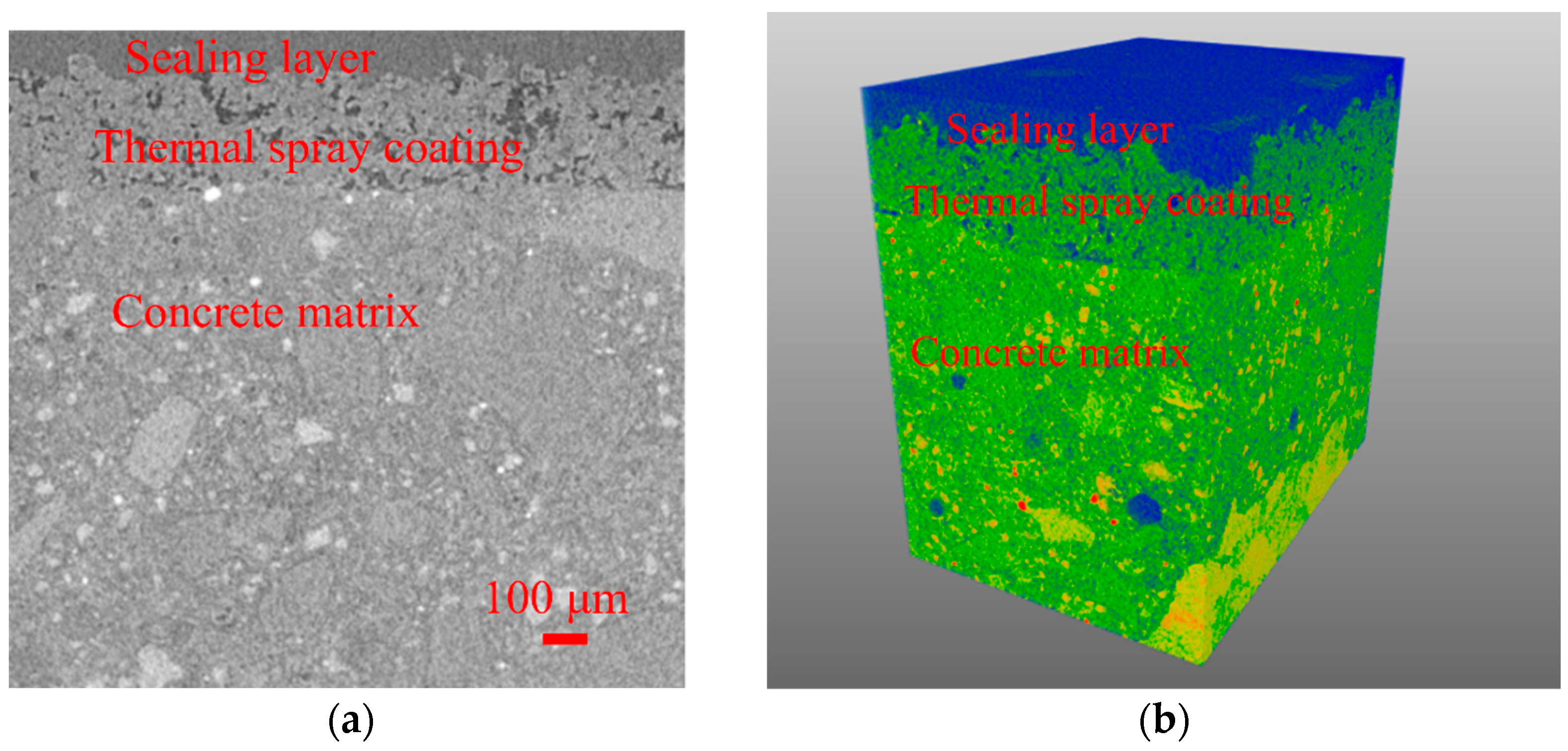
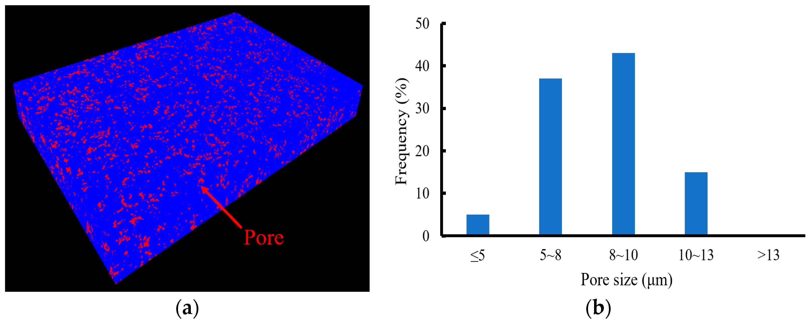
  • The SEM-EDS results demonstrate that the thermal-sprayed coating can completely cover the non-homogeneous multiphase concrete matrix. However, the formation mechanism of the interface between thermal-sprayed coating and concrete and its effect on the coating performance need to be studied. Based on X-CT three-dimensional scanning technology, the characteristics of porous structures inside the coating products can be intuitively grasped from a microscopic point of view.
  • To improve the coating performance and enhance the protective ability of concrete structures, it is necessary to improve the compactness and uniformity of the coating structure. At the same time, the composite of single-phase coating materials and the powder refinement of coating particles are also solutions to improve the toughness of the coating and enhance the wear resistance and mechanical properties of the coating. In the field of water conservancy and hydropower engineering, hydrophobic treatment and the long-term performance tracking of coating materials are also planned research directions.

Author Contributions

Conceptualization, C.W.; methodology, Y.S.; software, Y.S.; validation, Y.W., Y.S. and X.L.; formal analysis, Y.W.; investigation, Y.S. and Y.W.; resources, W.J.; data curation, Y.W.; writing—original draft preparation, C.W.; writing—review and editing, Y.S.; visualization, W.J.; supervision, C.W.; project administration, X.L.; funding acquisition, Y.S and X.L. All authors have read and agreed to the published version of the manuscript.

Funding

The authors would like to acknowledge the financial support received from the National Natural Science Foundation of China (52179122, U2040222, U2340229) and the Natural Science Foundation of Hubei Province (2022CFD026).

Institutional Review Board Statement

Not applicable.

Informed Consent Statement

Not applicable.

Data Availability Statement

Data are contained within the article.

Conflicts of Interest

The authors declare no conflicts of interest.

References

  1. Kannangara, T.; Joseph, P.; Fragomeni, S.; Guerrieri, M. Existing theories of concrete spalling and test methods relating to moisture migration patterns upon exposure to elevated temperatures—A review. Case Stud. Constr. Mater. 2022, 16, e01111. [Google Scholar] [CrossRef]
  2. Tian, Y.; Zhang, G.; Ye, H.; Zeng, Q.; Zhang, Z.; Tian, Z.; Jin, X.; Jin, N.; Chen, Z.; Wang, J. Corrosion of steel rebar in concrete induced by chloride ions under natural environments. Constr. Build. Mater. 2023, 369, 130504. [Google Scholar] [CrossRef]
  3. Zahedi, A.; Komar, A.; Sanchez, L.F.; Boyd, A.J. Global assessment of concrete specimens subjected to freeze-thaw damage. Cem. Concr. Compos. 2022, 133, 104716. [Google Scholar] [CrossRef]
  4. Jiang, L.; Pettitt, T.R.; Buenfeld, N.; Smith, S.R. A critical review of the physiological, ecological, physical and chemical factors influencing the microbial degradation of concrete by fungi. Build. Environ. 2022, 214, 108925. [Google Scholar] [CrossRef]
  5. Liu, P.; Chen, Y.; Yu, Z. Effects of temperature, relative humidity and carbon dioxide concentration on concrete carbonation. Mag. Concr. Res. 2020, 72, 936–947. [Google Scholar] [CrossRef]
  6. Kayondo, M.; Combrinck, R.; Boshoff, W.P. State-of-the-art review on plastic cracking of concrete. Constr. Build. Mater. 2019, 225, 886–899. [Google Scholar] [CrossRef]
  7. Woyciechowski, P.; Łukowski, P.; Szmigiera, E.; Adamczewski, G.; Chilmon, K.; Spodzieja, S. Concrete corrosion in a wastewater treatment plant–A comprehensive case study. Constr. Build. Mater. 2021, 303, 124388. [Google Scholar] [CrossRef]
  8. Moon, H.Y.; Shin, D.G.; Choi, D.S. Evaluation of the durability of mortar and concrete applied with inorganic coating material and surface treatment system. Constr. Build. Mater. 2007, 21, 362–369. [Google Scholar] [CrossRef]
  9. Pan, X.; Shi, Z.; Shi, C.; Ling, T.C.; Li, N. A review on concrete surface treatment Part I: Types and mechanisms. Constr. Build. Mater. 2017, 132, 578–590. [Google Scholar] [CrossRef]
  10. Almusallam, A.; Khan, F.M.; Maslehuddin, M. Performance of concrete coating under varying exposure conditions. Mater. Struct. 2002, 35, 487–494. [Google Scholar] [CrossRef]
  11. Li, G.; Dong, L.; Lei, M.; Du, J. Predicting carbonation depth for concrete with organic film coatings combined with ageing effects. Constr. Build. Mater. 2017, 142, 59–65. [Google Scholar] [CrossRef]
  12. Shohide, M.A. Fabrication and application of an innovative low cost-efficient polymer nano-composite as concrete protective coating. Int. J. Adhes. Adhes. 2024, 128, 103542. [Google Scholar] [CrossRef]
  13. Qu, H.; Feng, M.; Li, M.; Tian, D.; Zhang, Y.; Chen, X.; Li, G. Enhancing the carbonation and chloride resistance of concrete by nano-modified eco-friendly water-based organic coatings. Mater. Today Commun. 2023, 37, 107284. [Google Scholar] [CrossRef]
  14. Chi, J.; Zhang, G.; Xie, Q.; Ma, C.; Zhang, G. High performance epoxy coating with cross-linkable solvent via Diels-Alder reaction for anti-corrosion of concrete. Prog. Org. Coat. 2020, 139, 105473. [Google Scholar] [CrossRef]
  15. Wang, H.; Feng, P.; Lv, Y.; Geng, Z.; Liu, Q.; Liu, X. A comparative study on UV degradation of organic coatings for concrete: Structure, adhesion, and protection performance. Prog. Org. Coat. 2020, 149, 105892. [Google Scholar] [CrossRef]
  16. Chen, S.C.; Lin, W.T.; Huang, R.; Hsu, H.M. Performance of green concrete and inorganic coating materials. Materials 2021, 14, 832. [Google Scholar] [CrossRef] [PubMed]
  17. Franzoni, E.; Pigino, B.; Pistolesi, C. Ethyl silicate for surface protection of concrete: Performance in comparison with other inorganic surface treatments. Cem. Concr. Compos. 2013, 44, 69–76. [Google Scholar] [CrossRef]
  18. Jia, L.; Shi, C.; Pan, X.; Zhang, J.; Wu, L. Effects of inorganic surface treatment on water permeability of cement-based materials. Cem. Concr. Compos. 2016, 67, 85–92. [Google Scholar] [CrossRef]
  19. Li, G.; Ding, Y.; Gao, T.; Qin, Y.; Lv, Y.; Wang, K. Chloride resistance of concrete containing nanoparticle-modified polymer cementitious coatings. Constr. Build. Mater. 2021, 299, 123736. [Google Scholar] [CrossRef]
  20. Amer, M.; Curry, N.; Hayat, Q.; Sharma, R.; Janik, V.; Zhang, X.; Nottingham, J.; Bai, M. Cracking behavior of Gd2Zr2O7/YSZ multi-layered thermal barrier coatings deposited by suspension plasma spray. Coatings 2023, 13, 107. [Google Scholar] [CrossRef]
  21. Amer, M.; Curry, N.; Arshad, M.; Hayat, Q.; Janik, V.; Nottingham, J.; Bai, M. Unraveling the Cracking Mechanisms of Air Plasma-Sprayed Thermal Barrier Coatings: An In-Situ SEM Investigation. Coatings 2023, 13, 1493. [Google Scholar] [CrossRef]
  22. Lee, H.S.; Park, J.; Singh, J.K.; Choi, H.J.; Mandal, S.; Jang, J.M.; Yang, H.M. Electromagnetic shielding performance of carbon black mixed concrete with Zn–Al metal thermal spray coating. Materials 2020, 13, 895. [Google Scholar] [CrossRef]
  23. Wang, Y.P. A Study on Thermal Spraying Sacrificial Anode Applied in Concrete Structure Cathodic Protection. Adv. Mater. Res. 2014, 1015, 215–218. [Google Scholar] [CrossRef]
  24. Wang, L.; Ming, C.; Zhong, X.H.; Ni, J.X.; Tao, S.Y.; Zhou, F.F.; Wang, Y. Prediction of critical rupture of plasma-sprayed yttria stabilized zirconia thermal barrier coatings under burner rig test via finite element simulation and in-situ acoustic emission technique. Surf. Coat. Technol. 2019, 367, 58–74. [Google Scholar] [CrossRef]
  25. Madlmeir, S.; Radl, S. A coarse-grained parcel method for heat and mass transfer simulations of spray coating processes. Adv. Powder Technol. 2022, 33, 103590. [Google Scholar] [CrossRef]
  26. Guo, S.Y.; Luo, H.H.; Tan, Z.; Chen, J.Z.; Zhang, L.; Ren, J. Impermeability and interfacial bonding strength of TiO2-graphene modified epoxy resin coated OPC concrete. Prog. Org. Coat. 2021, 151, 106029. [Google Scholar] [CrossRef]
  27. Rogé, B.; Fahr, A.; Giguere, J.S.R.; McRae, K.I. Nondestructive measurement of porosity in thermal barrier coatings. J. Therm. Spray Technol. 2003, 12, 530–535. [Google Scholar] [CrossRef]
  28. Mather, B. Concrete durability. Cem. Concr. Compos. 2004, 26, 3–4. [Google Scholar] [CrossRef]
  29. GB/T 175-2020; Common Portland Cement; State Administration for Market Regulation. Standardization Administration of the People’s Republic of China: Beijing, China, 2020.
  30. DL/T 5055-2007; Technical Specification of Fly Ash for Use in Hydraulic Concrete. National Development and Reform Commission: Beijing, China, 2007.
  31. Yu, Q.; Rauf, A.; Zhou, C. Microstructure and Thermal Properties of Nanostructured 4 wt.% Al2 O3-YSZ Coatings Produced by Atmospheric Plasma Spraying. J. Therm. Spray Technol. 2010, 19, 1294–1300. [Google Scholar] [CrossRef]
  32. Loser, R.; Münch, B.; Lura, P. A volumetric technique for measuring the coefficient of thermal expansion of hardening cement paste and mortar. Cem. Concr. Res. 2010, 40, 1138–1147. [Google Scholar] [CrossRef]
  33. Szczucka-Lasota, B.; Węgrzyn, T.; Stanik, Z.; Piwnik, J.; Sidun, J. Selected parameters of micro-jet cooling gases in hybrid spraying process. Arch. Metall. Mater. 2016, 61, 621–624. [Google Scholar] [CrossRef]
  34. SL/T 3520-2020; Test Code for Hydraulic Concrete. Ministry of Water Resources of the People’s Republic of China: Beijing, China, 2020.
  35. ASTM D4541; Standard Test Method for Pull-Off Strength of Coatings Using Portable Adhesion Testers. ASTM International: West Conshohocken, PA, USA, 2009.
  36. Brito, V.R.S.S.; Bastos, I.N.; Costa HR, M. Corrosion resistance and characterization of metallic coatings deposited by thermal spray on carbon steel. Mater. Des. 2012, 41, 282–288. [Google Scholar] [CrossRef]
  37. Vuoristo, P. Thermal spray coating processes. In Comprehensive Materials Processing, 1st ed.; Volume 4: Coatings and films; Elsevier: Amsterdam, The Netherlands, 2014; pp. 229–276. [Google Scholar]
  38. Gizynski, M.; Chen, X.; Dusautoy, N.; Araki, H.; Kuroda, S.; Watanabe, M.; Pakiela, Z. Comparative study of the failure mechanism of atmospheric and suspension plasma sprayed thermal barrier coatings. Surf. Coat. Technol. 2019, 370, 163–176. [Google Scholar] [CrossRef]
  39. Jia, D.; Yi, P.; Liu, Y.; Sun, J.; Yue, S.; Zhao, Q. Effect of laser textured groove wall interface on molybdenum coating diffusion and metallurgical bonding. Surf. Coat. Technol. 2021, 405, 126561. [Google Scholar] [CrossRef]
  40. Zhou, Z.; Wang, Z.; Liang, H.; Wang, Y. Research progress of coating material/concrete interface. New Chem. Mater. 2020, 48, 281–284. [Google Scholar]
  41. Morales, A.; Piamba, O.; Olaya, J. Influence of gas pressure on the mechanical and tribological properties of Cu-Al coatings deposited via thermal spray. Coatings 2019, 9, 722. [Google Scholar] [CrossRef]
  42. Wang, H.; Zhou, X.; Liu, M.; Jia, L.; Huang, Y.; Wang, H. Research Progress of the Sealant Decreased Thermal Spray Coating Porosity. Mater. Rep. 2023, 37, 210–228. [Google Scholar]
Figure 1. SEM and XRD results of mullite powder: (a) SEM and (b) XRD.
Coatings 14 00885 g001aCoatings 14 00885 g001b
Figure 2. Concrete substrates for surface coating.
Coatings 14 00885 g002
Figure 3. The flow chart of coating preparation.
Coatings 14 00885 g003
Figure 4. The pull-off test of the thermally sprayed concrete.
Coatings 14 00885 g004
Figure 5. Friction coefficient curve of concrete substrate and coating.
Coatings 14 00885 g005
Figure 6. Thermal spray coating on concrete surfaces: (a) surface of the specimen after thermal spraying; (b) section of the specimen after thermal spraying.
Coatings 14 00885 g006
Figure 7. SEM photos of thermal spraying coating: (a) ×2000; (b) ×2500.
Coatings 14 00885 g007
Figure 8. XRD results of mullite coating.
Coatings 14 00885 g008
Figure 9. SEM image of coating-substrate cross-section: (a) 500×; (b) 200×.
Coatings 14 00885 g009
Figure 10. Elemental energy spectrum analysis diagram of the substrate-coating cross-section: (a) Si; (b) Al; (c) O; (d) all elements.
Coatings 14 00885 g010
Figure 11. CT scan image of the thermal spray coating structure on the concrete surface: (a) 2D grayscale image; (b) 3D coloured image.
Coatings 14 00885 g011
Figure 12. Pore distribution of coating: (a) 3D colour map; (b) histogram of pore size distribution.
Coatings 14 00885 g012
Table 1. Cement and fly ash chemical composition (%).
MaterialsCaOSiO2Al2O3Fe2O3MgOSO3Ignition Loss
Cement62.5319.904.944.552.541.770.82
Fly ash7.1454.2318.786.814.302.793.80
Table 2. Basic properties of cement.
MaterialsBlain Area
(m2/kg)
Setting TimeCompressive StrengthFlexural Strength
Initial Setting Time Final Setting Time 3 Days28 Days3 Days28 Days
Cement315.2213 min318 h:min15.345.33.767.81
GB175-2020≥250≥60 min≤720 h:min≥12.0≥42.5≥3.0≥6.5
Table 3. Basic properties of fly ash.
MaterialsFineness Blain AreaDensityRatio of Water
Requirements
Compressive Strength Ratio (%)
7 Days28 Days
Fly ash9.5%330.2 m2/kg2140 kg/m394%64.071.1
DL/T5055-2007≤12.0%--≤95%--
Table 4. Main test methods used and corresponding indicators.
Test TypeTest MaterialsTest MethodsTest Indicators
Macro testConcrete matrixCompressive testingCompressive strength
Tensile testingSplitting tensile strength
Wear testsRate of wear
CoatingInterface adhesion testingInterface adhesion
Wearing testingRate of wear
Microscopic testCoating and matrixSEM-XRD analysisMicrostructure and phase composition
SEM-EDS testingMicrostructure and elemental composition
X-CT three-dimensional meso-structure testingThree-dimensional visual reflection of the internal structure
Table 5. Adhesion test results of thermal spray coating on concrete surface.
Strength of Concrete Matrix (MPa)Average Interface Coating Adhesion (MPa)
Compression Tension
40.03.263.82
Table 6. Wear rate test results of concrete substrate and coating.
Reference Sample (g)After Testing (g)Rate of Wear (‰)
Concrete matrix12.739612.73880.06
Coating12.466212.46590.02
Disclaimer/Publisher’s Note: The statements, opinions and data contained in all publications are solely those of the individual author(s) and contributor(s) and not of MDPI and/or the editor(s). MDPI and/or the editor(s) disclaim responsibility for any injury to people or property resulting from any ideas, methods, instructions or products referred to in the content.

