Article

Microstructure and High-Temperature Mechanical Properties of a Superalloy Joint Deposited with CoCrMo and CoCrW Welding Wires

3D Printing Research and Engineering Technology Center, Beijing Institute of Aeronautical Materials, Beijing 100095, China
*
Authors to whom correspondence should be addressed.
Coatings 2024, 14(7), 892; https://doi.org/10.3390/coatings14070892 (registering DOI)
Submission received: 7 June 2024 / Revised: 5 July 2024 / Accepted: 15 July 2024 / Published: 17 July 2024
(This article belongs to the Section Surface Characterization, Deposition and Modification)

Abstract

:
The preparation of a single crystal superalloy surface overlay welding coating to improve its high-temperature mechanical properties is of great significance for prolonging the service life of blades. This work selected two types of welding wire alloys, CoCrMo and CoCrW, to prepare coatings on the surface of a single crystal superalloy. A comparative study was conducted on their mechanical properties, such as tension, compression, fatigue, durability, and wear at a high temperature of 900 ℃, aiming to reveal the high-temperature mechanical properties of the two types of welding coatings. Results showed that the average high-temperature tensile strength of the CoCrMo welded specimen was smaller than that of the CoCrW welded specimen; the average high-temperature duration of CoCrMo welded specimens at 150 MPa was lower than the average duration of CoCrW welded specimens; the high-temperature fatigue life of CoCrMo welded specimens at 220 MPa was 7.186 × 10⁵; and the average high-temperature wear rate of CoCrMo sample was 3.64 × 10⁻⁶ mm3·N−1·m−1. The CoCrW alloy was more wear resistant than CoCrMo. The hardness of CoCrMo welded joints gradually increased from the substrate to the heat-affected zone and then to the fusion zone, and was much higher in the fusion zone than in the CoCrW alloy.

1. Introduction

The low-cost and second-generation single crystal superalloy (DD6) has a high content of high-temperature-resistant elements (W, Mo, Ta, Re, Nb), with a content of approximately 19.5 wt.% [1,2]. Its tensile and creep endurance properties could be comparable to second-generation single crystal high-temperature alloys SC180, René N5, CMSX-4, and PWA1484 [3,4,5]. The yield strength of the DD6 alloy is approximately 981 MPa at 760 °C. Its creep endurance lives are approximately 484 h under conditions of 1093 °C/124 MPa [6]. Due to its excellent high-temperature fatigue performance, the DD6 alloy is widely used as a raw material for high-temperature components such as turbine blades in aircraft engines. However, there is high-temperature and pressure friction between the adjacent serrated crown mating surfaces of turbine blades, which can easily create gaps between the mating surfaces and reduce the efficiency of aircraft engines. Preparing a wear-resistant layer on the surface of DD6 to improve its friction and wear performance is of great significance for prolonging the service life of blades. At present, the preparation of wear-resistant layers mainly adopts manual argon arc welding, plasma spraying, and plasma cladding. The surface strengthening and modification of single crystals mainly focus on laser carbon alloying, nitrogen alloying, boron alloying, and multi-element alloying. Taking the blade of a shot blasting machine as an example, wear and crack initiation and other damages start from the surface of the blade. According to the material and working environment requirements of the blade, high hardness and wear-resistant flux-cored welding wire is usually selected as the welding material. Then, submerged arc welding, gas welding, or equal ion arc welding are used as welding processes to repair the worn part of the blade [7,8].
Overlay welding technology is widely used due to its ability to achieve the combination of the substrate and wear-resistant overlay layer, with a deep bonding layer, high bonding strength, no obvious interface between the substrate and overlay layer, economic advantages, and high production efficiency [9,10,11,12]. All welding processes affect the surface quality of the welding layer, the deposition and quality of the weld seam, and the geometric shape of the weld bead with the same processing principle [13], which largely depends on their process parameters. The common processing parameters that affect the surface quality of the overlay welding process mentioned above are mainly welding current, cooling conditions, interlayer temperature, welding speed, and flux-cored welding wires with different alloy powder compositions. According to the comparison standard of the coating material system, as well as the respective advantages, disadvantages, and application scope of these coating materials, several common self-fluxing alloy powders are shown in Table 1.
Co-based coatings have excellent wear resistance, corrosion resistance, thermal stability, high strength, high hardness, and are easy to form into simple solid solutions, making them one of the ideal coating materials for improving the surface properties of substrates. The Co-Cr-Mo alloy is a solid solution formed with cobalt as the basic component, which generally contains alloying elements such as chromium and molybdenum. The solid solution of molybdenum element with a mass fraction of 5% to 7% in the alloy can refine grain size in the matrix, and the atomic radius of molybdenum is larger than that of cobalt. The solid solution in the cobalt matrix can become a barrier for dislocation flow and, after casting or forging, the strength of the alloy can be effectively improved. The higher chromium content in the alloy can form a thin and dense oxide layer on the surface of the alloy, improving its corrosion resistance and wear resistance [15,16].
The CoCrW alloy is also known as the Stellite alloy. The stacking fault energy of elemental Co is low, and it is easy to form a large number of stacking fault strengthening matrices. The solid solution of alloy elements such as W and Cr in the matrix will also cause solid solution strengthening. Cr element could improve the corrosion resistance of the CoCrW alloy [17,18]. In addition, the precipitation of hard carbides will cause carbide strengthening. These characteristics of the CoCrW alloy make it have excellent wear resistance, corrosion resistance, high-temperature strength, and hardness [19]. There are two isomers of elemental Co, which are face-centered cubic structures γ-Co and closely packed hexagonal structures ε-Co; the former is a high-temperature stable phase, while the latter is a low-temperature stable phase. ε → γ, the transition temperature is approximately 430 °C, and γ→ε, the transformation temperature of the CoCrW alloy is approximately 390 °C [20]. Due to the fact that alloying elements such as W, Cr, and Mo can alter the stability of the two isomers, the actual transformation temperature of the CoCrW alloy may differ from that of elemental Co, and even differ significantly. During the cooling process, the chemical driving force of transformation is very low, so the main reaction is γ-Co organization at room temperature. The composition phase of the CoCrW alloy is generally γ-Co, M7C3, and M23C6, but when the content of W is higher, the composition phases of the alloy will also include M6C, M12C, Co3W, Co7W6, etc. [21,22].
The preparation of a deposition layer on the DD6 alloy surface using overlay welding technology can effectively improve the friction and wear performance of the alloy surface, but there is relatively little research on the preparation of a CoCr alloy deposition layer on the surface of a DD6 alloy. The influence of a CoCr alloy deposition layer on the surface properties of a DD6 alloy needs further exploration. Based on this, this work prepared the CoCr-based deposition layer on the surface of a DD6 alloy through overlay welding manufacturing technology, studied the effect of heat input on cracks in the heat-affected zone, and analyzed the microstructure characteristics, hardness distribution law, and friction and wear performance of the deposition coating in order to provide a reference basis for the preparation of CoCr-based wear resistant coatings on a DD6 alloy.

2. Test Materials and Methods

The experiment used overlay welding technology for surface modification treatment on the DD6 substrate. The DD6 substrate was cut into a plate, as shown in Figure 1a, with a thickness of 2 mm. The butt weld was cut into a V-shaped groove and the welding wire filled the groove. The welding process parameters were: a welding current of 23–34 A, Ar protective gas flow rate of 10 ± 2 L/min, and diameter of the welding gun nozzle of 8–14 mm. Two types of welding wires were selected for comparative study: Co-Cr-Mo and Co-Cr-W alloys. The diameter of the two types of welding wires was 1.6 mm, and the main chemical composition is shown in Table 2.
After the overlay welding, the mechanical performance was tested. Specimens high-temperature tensile, fatigue, and endurance properties were taken from the welding test plate (Figure 1b). The specimens after being machined are shown in Figure 1c. The tensile test was conducted on an electronic high-temperature universal testing machine, which was equipped with a 1100 °C high-temperature furnace, an environmental box, and a room temperature high-temperature extensometer. The temperature control error was ≤±2 °C and the relative error of the test force indication was ≤±0.5%. The experimental environment was atmospheric. The plate-shaped specimen was clamped onto the testing machine by connecting the pin and the 3 mm hole at both ends of the tensile specimen. The loading rate was 0.1 mm/min (i.e., the strain rate was 1.2 × 10⁻⁴ s−1). The high-temperature test involves gradually heating the clamped specimen to the tensile test temperature, holding it for 30 min, and then applying the test load. The room temperature and high-temperature tensile tests were conducted in accordance with the national standards: Metal Materials Room Temperature Tensile Test Method (GBT228.1-2010) [23] and Metal Materials High-Temperature Tensile Test Method (GB/T4338-2006) [24].

3. Results and Discussion

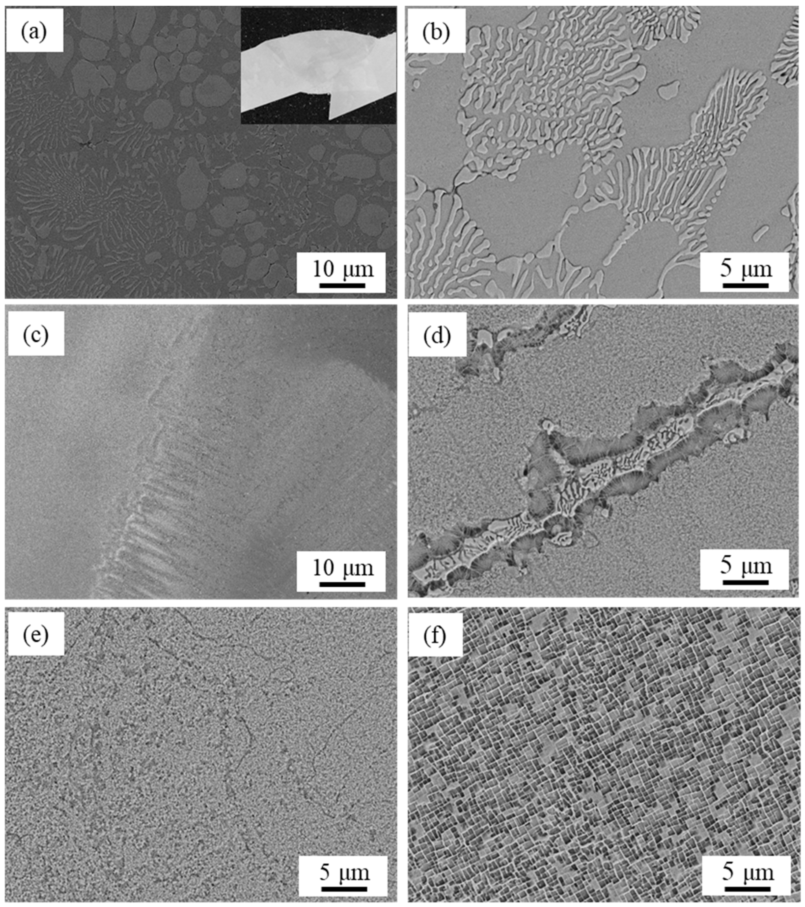
3.1. Microstructure of CoCrMo and CoCrW

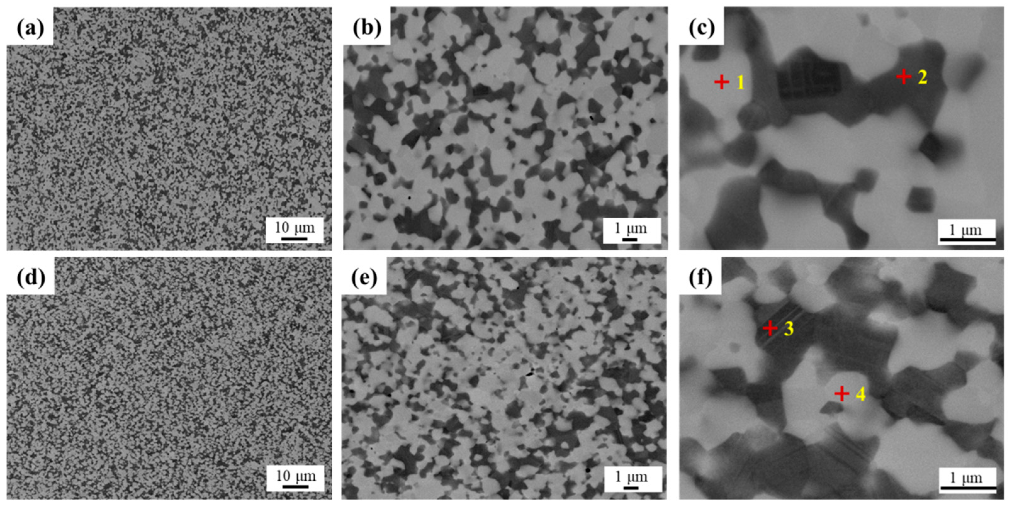
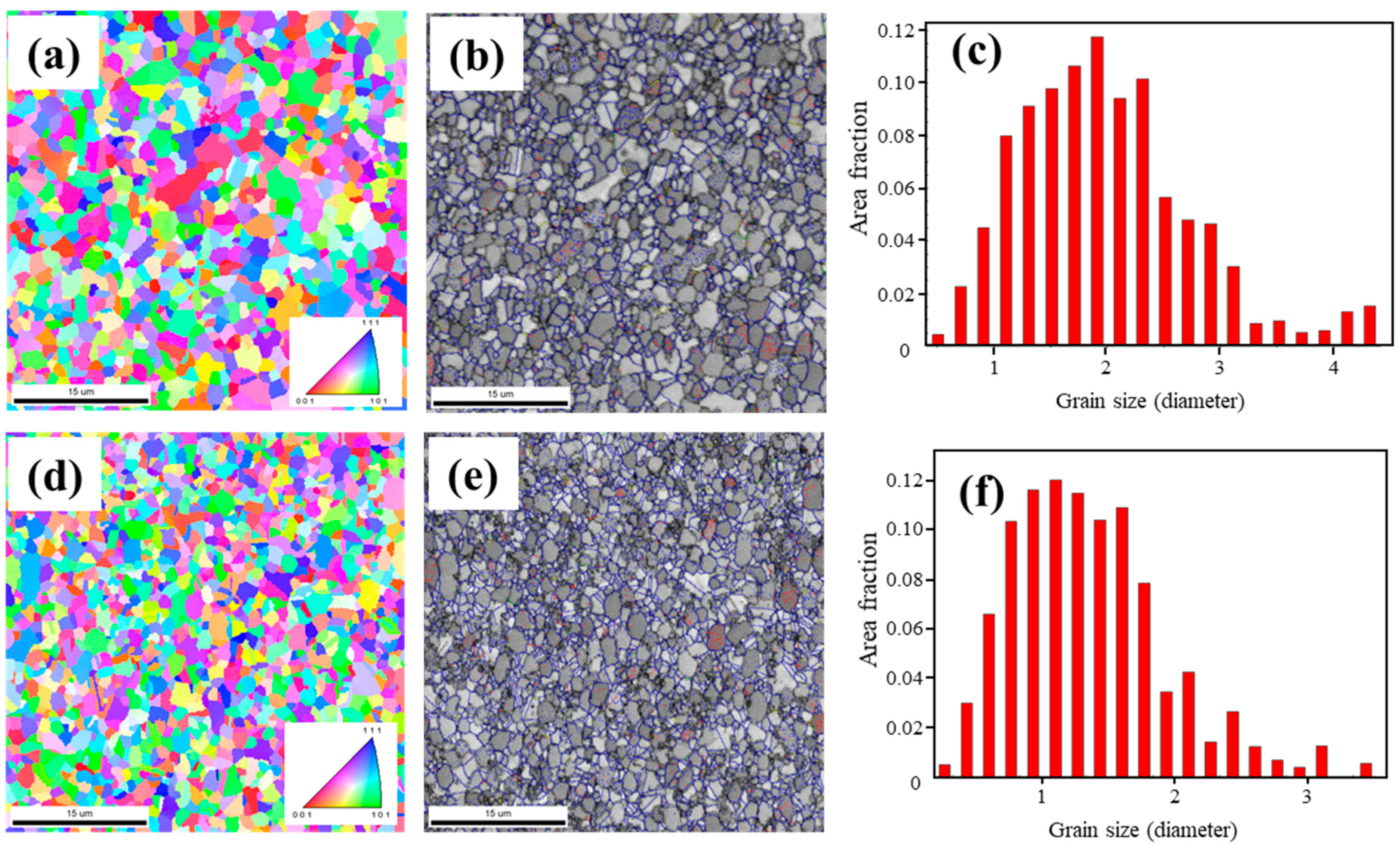
3.1.1. CoCrMo Welding Wire

The matrix phase composition of the CoCrMo welding wire was composed of the α and ε phase. The α phase had a face-centered cubic (FCC) structure and was a non-equilibrium phase. The ε phase had a dense hexagonal (HCP) structure and an equilibrium phase [25]. As different overlay welding methods, there was a significant difference in the proportion of solid solution phases between α and ε in CoCrMo alloys. Within the same chemical composition range, the different content of alloy phases resulted in significant differences in the properties of CoCrMo alloys produced by different manufacturing methods [26]. The tensile strength, yield strength, and elongation of the CoCrMo alloy with higher non-equilibrium structures α were significantly higher than those of the CoCrMo alloy deposited by overlay welding.
The microstructure of the CoCrMo alloy is shown in Figure 2. Based on the distribution of components, the phase composition of the organization can be determined. It could be determined that the white and coarse phase in the microstructure was the equilibrium structure CoCr phase of the CoCr alloy, as shown in Table 3. The black coarse phase was a non-equilibrium CoMo phase, and a large number of twin structures with flat interfaces were formed between these phases. The microstructure of the CoCrMo alloy was equiaxed, with an average grain size of 2 µm. The carbide phase appeared in a gray discrete irregular block shape with relatively low content. Grain size and distribution in two directions showed uniformity, as shown in Figure 3.

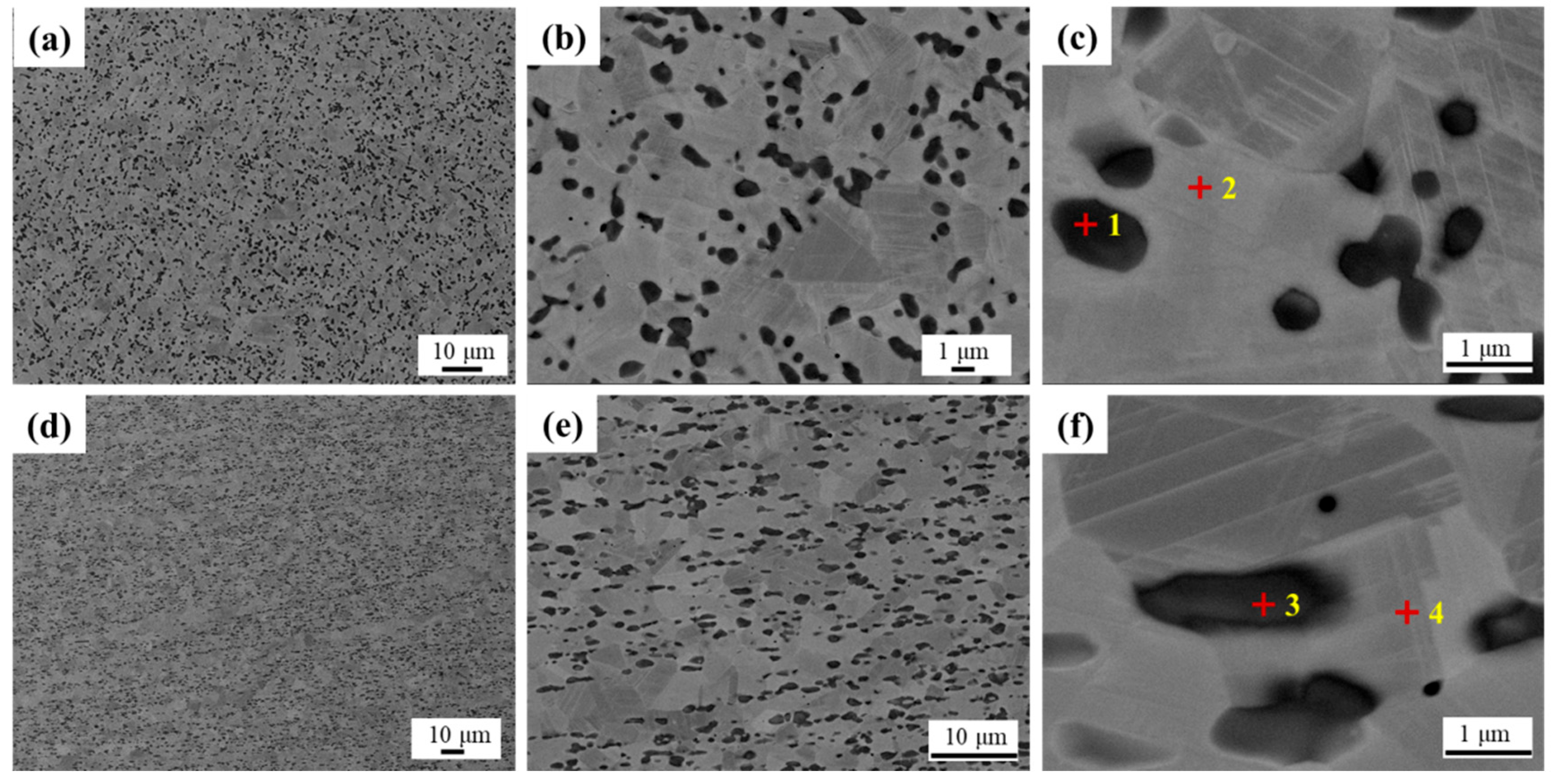
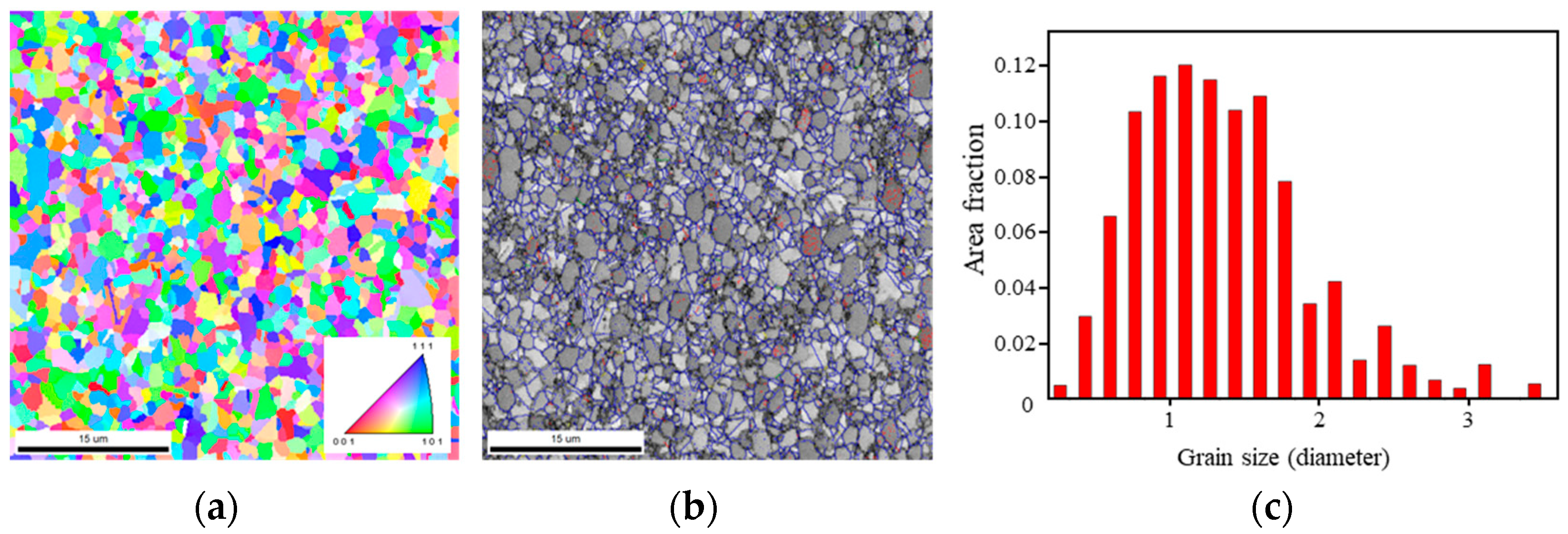
3.1.2. CoCrW Welding Wire

The CoCrW alloy was mainly composed of Co, CoCr, and CoWC phases, as shown in Figure 4 and Table 4. In the transverse direction, CoCr phases were distributed uniformly in the matrix and most of shapes were elliptic. In the longitudinal direction, the deformation and distribution with a certain direction were formed due to the preparation and rolling action, and the CoCr was mutually flat. The CoCrW alloy was mainly composed of equiaxed crystals, and a large number of twin crystals were locally formed in the CoCrW matrix. The large white CoCrW phase was the equilibrium CoCr alloy CoCrW phase. The black coarse CoCr phase was the non-equilibrium phase, and these phases also formed a large number of twin structures, as shown in Figure 5.

3.2. Microstructure of Overlay Welding on the DD6

3.2.1. CoCrMo Overlay Welding

The microstructure of the cross-section of the CoCrMo alloy overlay could be divided into four regions: heat-affected zone, diffusion layer of cellular crystals and columnar dendrites with certain directions, and planar crystal zone (fusion zone).
Diffusion zone. The transition layer between the overlay layer and DD6 substrate was not obvious, and columnar dendrites with certain directions were formed at the interface. The melted welding wire and partially melted substrate diffused with each other, resulting in good metallurgical bonding. When observing the microstructure at the interface at high magnification, it was found that a relatively regular and featureless ‘white bright band’ was formed, namely the fusion zone, which was a regular planar crystal. Diffusion occurred near the fusion line, with Fe, Cr, and Co main elements, as shown in Table 5. The content of Fe gradually decreased as it moved away from the interface, while the content of Cr and Co increased as it approached the overlay layer, indicating good metallurgical bonding at the interface. The diffusion layer was approximately 0.2 mm, and the phase angle between the layer γ′ phase and blade substrate γ′ was less than 15°, and no cracks or recrystallization was found.
In the fusion zone. The dendritic structure near the surface of the stack layer was fine and dense due to the multiple heat dissipation channels near the surface, fast cooling speed, and an unstable growth direction. The columnar dendritic zone in the middle of the overlay layer was characterized by columnar dendritic growth that was generally oriented perpendicular to the interface. The main composition phase of the overlay layer was y-Co. According to the crystal growth theory, y-Co grew preferentially along the <100> direction [27]. Due to the fact that the molten pool mainly relied on the base material for heat dissipation at the bonding interface, the heat flow direction at the bottom of the molten pool was basically parallel to the (1001) universal direction of the FCC crystal. The eutectic structure was mainly composed of Co dendrites and carbides of Cr, which contained substitution elements of Cr containing Co, W, and Fe.
The direction of the flat and elongated melt pool was similar, and there were layered structures with different directions penetrating the melt pool. The width of the elongated molten pool was approximately 80~120 µm. This complies with the laser spot size of 100 µm. The width of the melt pool was less than 100 µm, because there was some overlap in the molten pool, and the width of the molten pool was greater than 100 µm due to the thermal effect of the laser. Based on Figure 6, the longitudinal section of the specimen was composed of melt pools with similar sizes, and the width, height, and distance between adjacent centerlines of the melt pool were approximately 100 µm, 40 µm, and 50 µm.
Heat-affected zone. The γ′ phase size was small and blurry, the matrix structure was uniform, and the high-magnification structure was mainly composed of γ and γ′ phase composition, where γ′ was approximately 0.4~0.5 µm; no abnormalities were found. The cross-sectional shape of the elongated molten pool extended into the DD6. These elongated molten pools had two types of microstructures: cellular and columnar crystals, with a diameter of approximately 1 µm. The compound at the grain boundary was a honeycomb-like precipitate, which also existed in the Al-Si alloy [28], 316L stainless steel [29], and 18Ni-300 martensitic aging steel [30]. The honeycomb precipitate was confirmed to be M23C6 (M = Cr, Mo, Co) carbide [31,32,33].
Figure 6f shows a schematic diagram of the crystal plane and orientation index in the cubic crystal system. The OO′, OA, and OC in the figure were [001], [100], and [010] crystal directions, respectively. The bottom OABC was the (001) crystal plane, and the plane O′ A′ BC formed by the red border was the (011) crystal plane. The shaded O′ AC plane enclosed by the blue dashed line was the (111) crystal plane.

3.2.2. CoCrW Overlay Welding

The weld seam width of the CoCrMo welding joint was approximately 4.6 mm, and the welding fusion zone was highly granular and had a dendritic casting structure. The diffusion layer was less than 0.2 mm, and the phase angle between the γ′ phase and blade substrate γ′ was less than 15°; no cracks or recrystallization were found. The γ′ phase size in the microstructure of the heat-affected zone was small and blurry, the matrix structure was uniform, the high-magnification structure was mainly composed of γ and γ′ phase composition, where the γ′ phase size was approximately 0.4~0.5 µm, and no abnormalities were found, as shown in Figure 7.
According to the graph, the four phases were respectively rich Co matrix phases: rich in Co, Cr small dendrites, rich in W phase, and rich in Cr large dendrites. The rich Co matrix phase was γ-Co. Rich Co and Cr phases were CrCo, which were intermetallic compounds of CrCo. Rich W phase was M6C, and the rich Cr phase was Cr23C6.
There were many Ni elements at the bottom of the sedimentary layer, indicating that the dilution rate of Co-based alloys at the bottom of the sedimentary layer was relatively high. During the deposition process, the melted components of the matrix entered the sedimentary layer through convection in the melt pool. The content of Co element increased along the deposition height direction, indicating that there was a large amount of matrix phase in the middle and top of the deposition layer during the rapid melting and solidification process γ-Co and CrCo intermetallic compound phase formation. The content of Cr, W, and C elements in various regions of the sedimentary layer was relatively stable, and Cr, W, and Co dissolved under laser deposition γ-Co produce lattice distortion and high hardness carbides M6C and Cr23C6.
The distance selected between the center of any indentation and the edge of the specimen should be at least 2.5 times the average diameter of the indentation, and the distance between the centers of two adjacent indentations should be at least three times the average diameter of the indentation as the qualification criterion for hardness testing. Two metallographic specimens were selected for both CoCrMo and CoCrW welded joints. The microhardness gradient was tested on the metallographic specimens from left to right, with a measurement point spacing of 0.1 mm. The test results are shown in Figure 8. The hardness of CoCrMo welded joints increased in the heat-affected zone, while there was a slight decrease in the fusion zone. The hardness range of the fusion zone of the weld was approximately 430~520 HV. The hardness of CoCrW welded joints gradually increased from the substrate to the heat-affected zone and then to the fusion zone, reaching its highest point in the middle of the fusion zone. The hardness range of the fusion zone of the weld was 550~800 HV, which was much higher than that of the CoCrMo welded fusion zone.

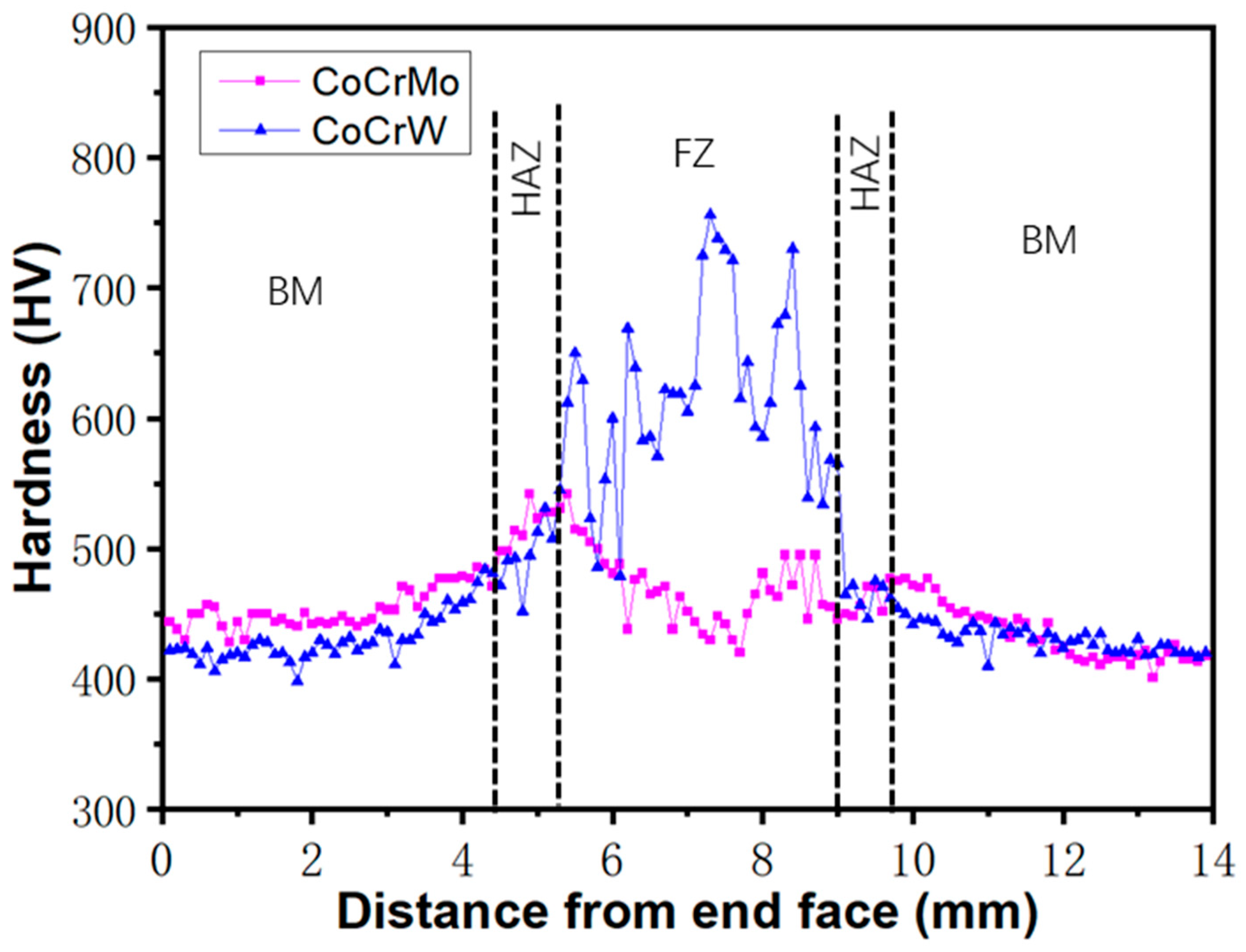
3.3. Mechanical Properties of DD6 Overlay Welded Joints

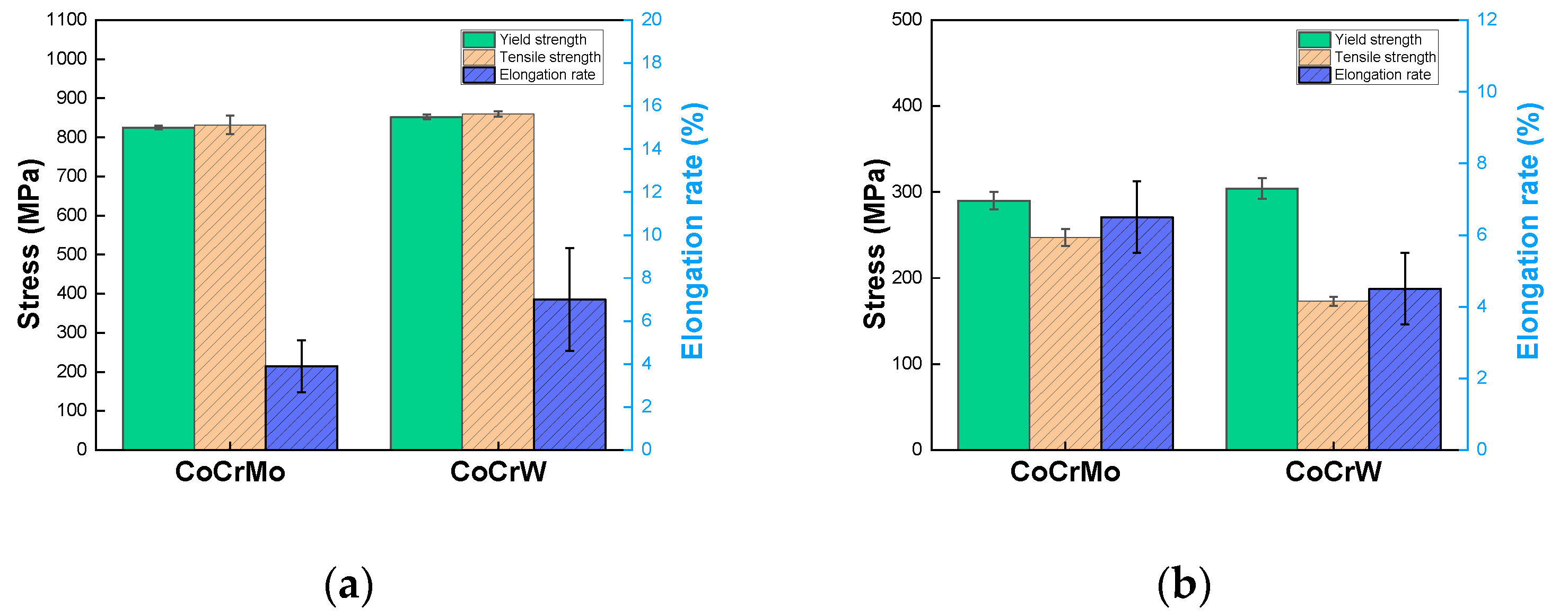
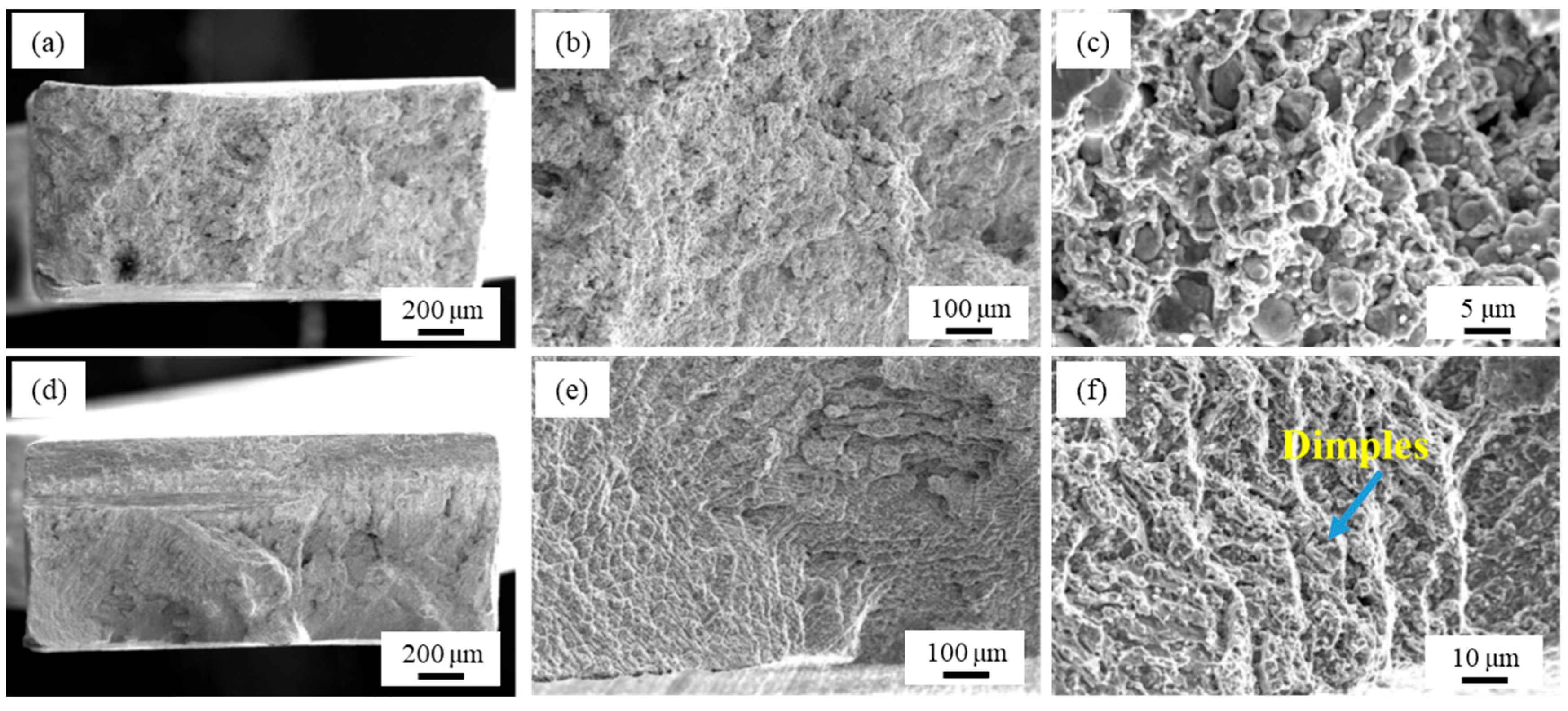
3.3.1. High-Temperature Tensile Performance of Overlay Welded Joints

Figure 9a shows the comparison of room temperature tensile results between CoCrMo and CoCrW welded specimens. It can be seen that the average tensile strength of CoCrMo welded specimens was 832 MPa, which was lower than that of the CoCrW welded specimens, whose average tensile strength was 860 MPa. The average elongation after fracture of CoCrMo welded specimens was 3.9%, which was lower than that of the CoCrW welded specimens, whose average elongation after fracture was 11.3%. The tensile strength deviation value of the CoCrMo room temperature tensile specimen was 24, which was greater than that of the CoCrW specimen, which was 7. The deviation value of elongation after fracture for CoCrMo room temperature tensile specimens was 1.2, which was smaller than that of the CoCrW specimens, which was 2.4.
Figure 9b shows the comparison of the high-temperature tensile results of CoCrMo and CoCrW welded specimens at 900 °C. The average high-temperature tensile strength of CoCrMo welded specimens was 290 MPa, which was smaller than that of the CoCrW welded specimens. The elongation after fracture of CoCrMo welded specimens was 6.5%, greater than that of the CoCrW welded specimens, which was 4.5%. The average tensile strength deviation of CoCrMo was 18, less than that of the CoCrW specimens, which was 43. The deviation of the average elongation after fracture of the CoCrMo high-temperature tensile test was 1.8, greater than that of the CoCrW specimens, which was 0.69.
Figure 10a–c show the fracture of CoCrMo room temperature tensile specimens. From the overall judgment of the fracture surface, it presented a mixed fracture model of ductile and fragile. The surface was bright, and there was no obvious oxidation on the cross section, and the fracture was located in the middle of the weld position. The plastic deformation was not obvious, and the fracture microstructure was mainly characterized by cleavage and quasi cleavage, with some showing layered fracture characteristics. Slippage traces could be seen on the larger side of the shear plane. Figure 10d–f show the fracture analysis of CoCrW room temperature tensile specimens. The surface was bright, and they were all fractured at the weld position. There was no obvious oxidation on the fracture surface, and the plastic deformation at the fracture surface was obvious, with visible necking. The microstructure of the fracture surface was mainly characterized by cleavage and quasi cleavage, with many small shear planes.
Figure 11 shows the fracture of CoCrMo and CoCrW high-temperature tensile specimens, all of which are located at the weld seam. The surface of the high-temperature tensile specimens displayed oxidation. The obvious necking fracture morphology was mainly ductile dimples, with a small amount of cleavage.

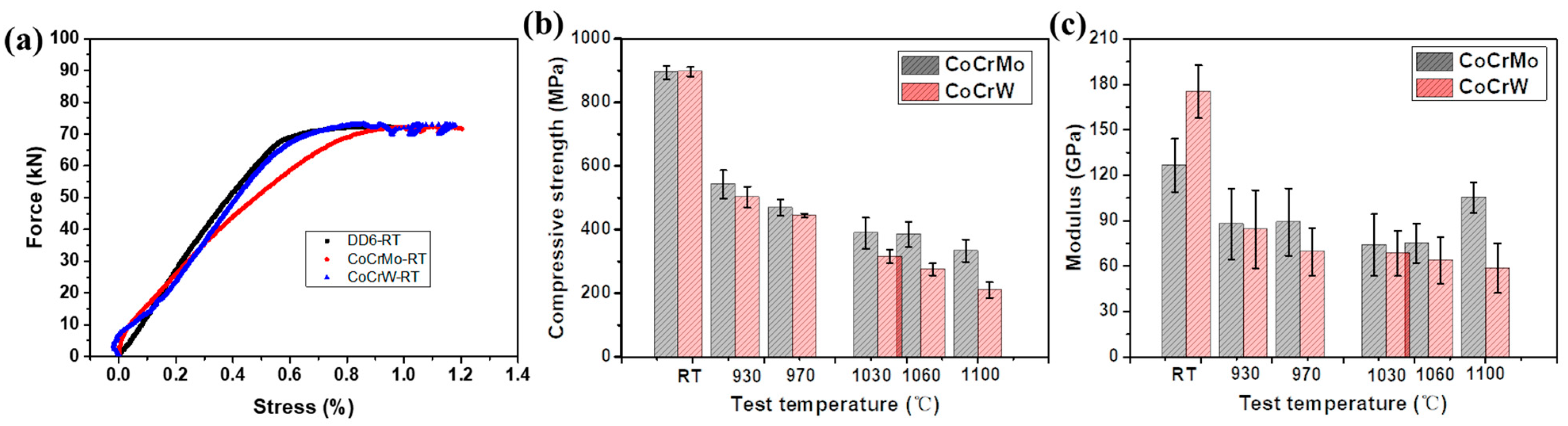
3.3.2. High-Temperature Compression Performance of Overlay Welded Joints

The true stress–strain curves of CoCrMo and CoCrW overlay joints are shown in Figure 12a. The trend of flow stress with deformation temperature during high-temperature compression deformation was the same; that is, with the increase in temperature, the flow stress gradually decreased. The trend of rheological stress variation with strain in the two types of joints was basically the same: after compression begins, with the increase in strain, the true stress growth rate was very fast, in a straight-line state and raised at a high slope. When a certain peak was reached, with the increase in true strain, the growth rate of rheological stress slowed down and the magnitude of stress value hardly changed much. At this point, the rheological stress no longer changed linearly. As the strain continued to increase, the curve showed a downward trend and gradually stabilized, reaching a relatively stable value, which was the steady-state stress. The reason for its formation was generally believed to be the result of the combined effect of strain hardening and recrystallization dynamic softening during high-temperature deformation, and the relationship between softening and hardening was reflected in the true stress–strain curve. In the early stage of deformation, the dislocation density inside the grains continuously increased, leading to work hardening and a rapid increase in rheological stress. After work hardening, the material was in an unstable state, and the increase in internal energy provided a driving force for dislocation slip. The material began to undergo dynamic recovery, and the effect of work hardening was gradually offset, leading to dynamic recrystallization and material softening. When work hardening and recrystallization softening reached equilibrium, the flow stress reached its maximum value. As the deformation continued to increase, softening occurred over a large range, strain hardening and dynamic recrystallization softening reached dynamic equilibrium again, and the rheological stress entered a stable state.
According to GB/T 7314-2017 [34], the room temperature (RT), 930 °C, 970 °C, 1030 °C, 1060 °C, and 1100 °C compressive strengths of the overlay weld joints were tested. The number of specimens at each temperature point was not less than three, and the morphology characteristics of the wear-resistant layer at both ends of the specimens were observed after the test. Figure 12b,c show the high-temperature compression performance and modulus of CoCrMo and CoCrW overlay joints.

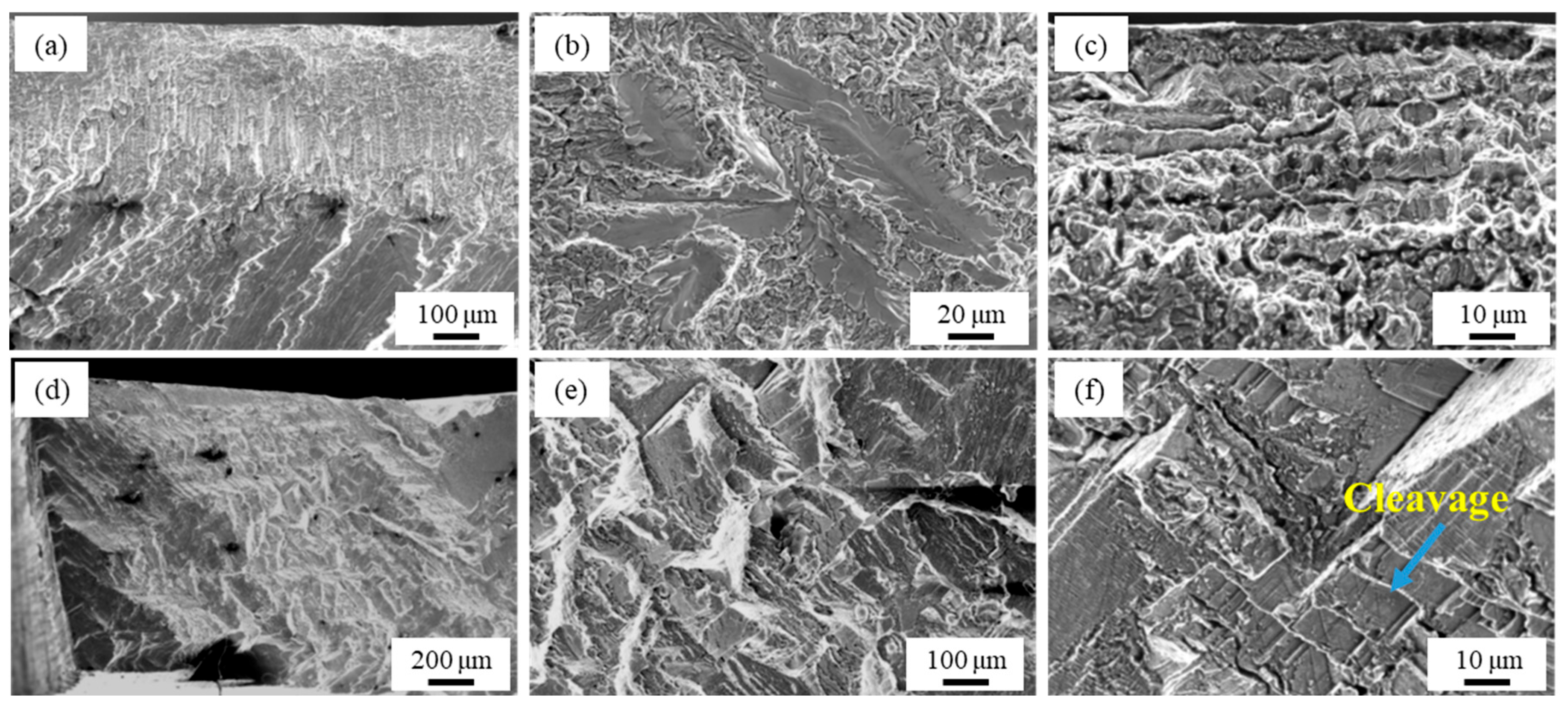
3.3.3. Fatigue Performance of Overlay Welded Joints

At the high temperature of 900 °C and the stress level of 150 MPa, the average endurance time of CoCrMo welded specimens was 1.17 h, which was lower than that of CoCrW welded specimens, which was 5.33 h. When the stress level increased to 200 MPa, the average duration of CoCrMo welded specimens was only 0.42 h, which was lower than that of CoCrW welded specimens, which was 2 h, as shown in Figure 13.
Figure 14a–c show the fracture analysis of high-temperature endurance specimens of CoCrMo welded specimens. The surface of the endurance specimen displayed oxidation, and the fracture was located in the middle of the working section without obvious necking. Figure 14d–f show the fracture of high-temperature persistent specimens of CoCrW welding, all of which also were located at the weld seam. The surface of the persistent specimen also experienced oxidation, and the fracture was located in the middle of the working section without obvious necking. It fractured along interdendritic boundaries in a layered manner, with ductile dimples as the main microstructure and a small amount of cleavage planes visible. From the overall judgment of the fracture surface, it presented a fracture model of ductile.

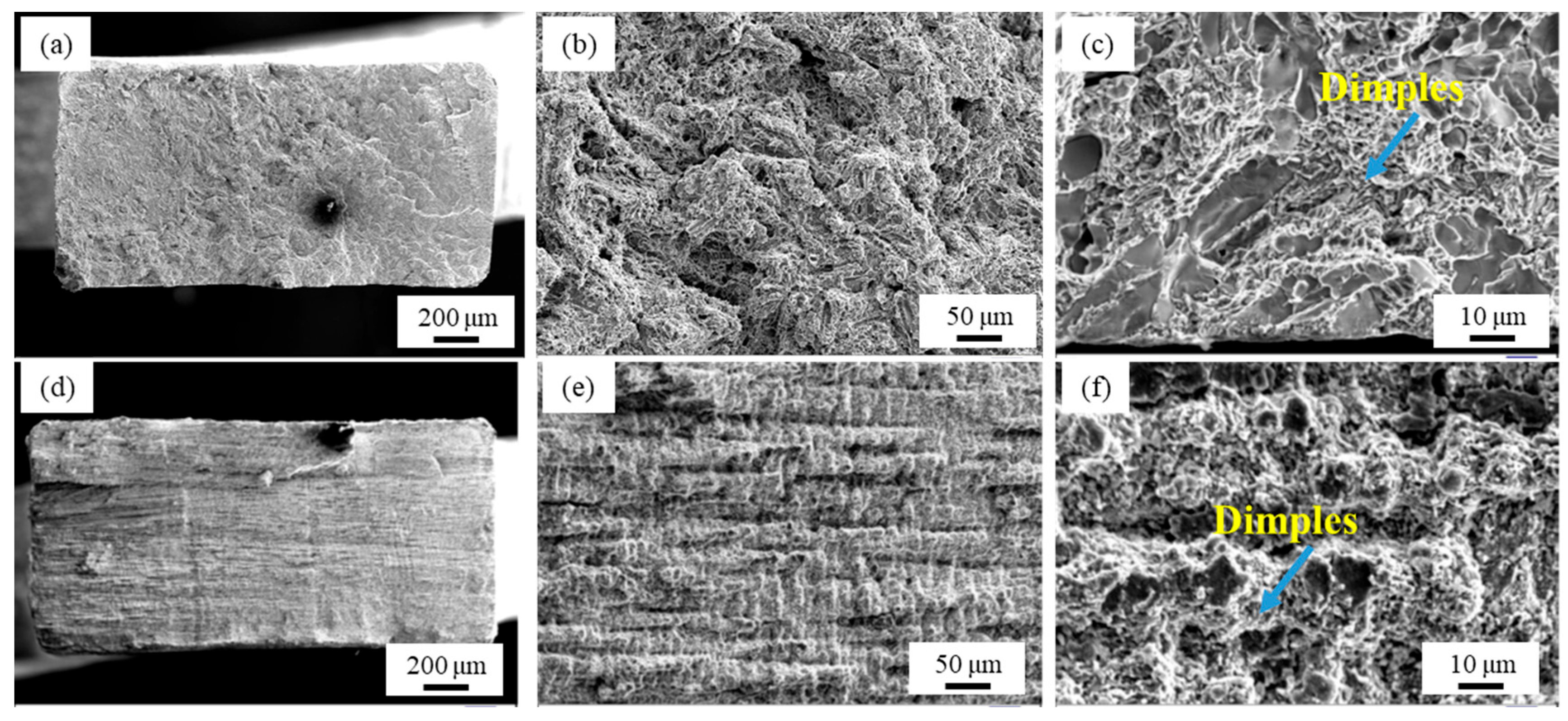
3.3.4. High-Temperature Fatigue and Wear Performance of Overlay Welded Joints

Table 6 shows the fatigue results of the stress ratio R = −1 for two types of welding wire specimens, CoCrMo and CoCrW, at 900 °C, at 220 MPa, 180 MPa, and 150 MPa. The wear performance was not an inherent characteristic of the material but related to the working conditions during the wear process (such as load speed, temperature, environmental factors, etc.), the material properties, and interactions. The evaluation of the room temperature wear performance of two Co-based alloy overlay layers was based on DD6 as the “standard”, and wear tests were conducted under the same conditions. The weight-loss method was used to evaluate the resistance of the three cobalt-based alloy overlay layers, that is, the relative wear resistance of the three alloy overlay layers. The wear resistance of materials was usually expressed as the reciprocal of the wear rate. Namely, ε = 1/W. In the formula, ε was the wear resistance of the material, W was the wear rate generated by the material within a unit time or unit movement distance and also the amount of wear rate. The relative wear resistance was the ratio of the wear resistance of the test material to the “standard” material under the same operating conditions.
Table 7 shows the comparison of wear rate and volume between the base material and overlay layers. It can be seen that under different dry friction and wear losses of different welding layers at different times, the wear amount of the two cobalt-based alloy overlay welding layers was much smaller than that of DD6. As the wear test was carried out, under stress, the worn surface undergoes a work hardening phenomenon, and the wear loss weight of all alloy layers gradually decreased over time. It can be seen that the average high-temperature wear rate of CoCrMo specimens was 3.64 × 10⁻⁶ mm3N−1m−1, which was higher than that of CoCrMo specimens (2.83 × 10⁻⁶ mm3N−1m−1), indicating that CoCrW was more wear resistant than CoCrMo at 900 °C.

4. Conclusions

A comparative study was conducted on their mechanical properties such as tension, compression, fatigue, durability, and wear at the high temperature of 900 °C, aiming to reveal the high-temperature mechanical properties of the two types of welding coatings:
(1)
The average room temperature tensile strength of CoCrMo welded specimens was 832 MPa, which was lower than CoCrW welded specimens. The average high-temperature tensile strength of CoCrMo welded specimens at 900 °C was 290 MPa, which was smaller than that of CoCrW welded specimens;
(2)
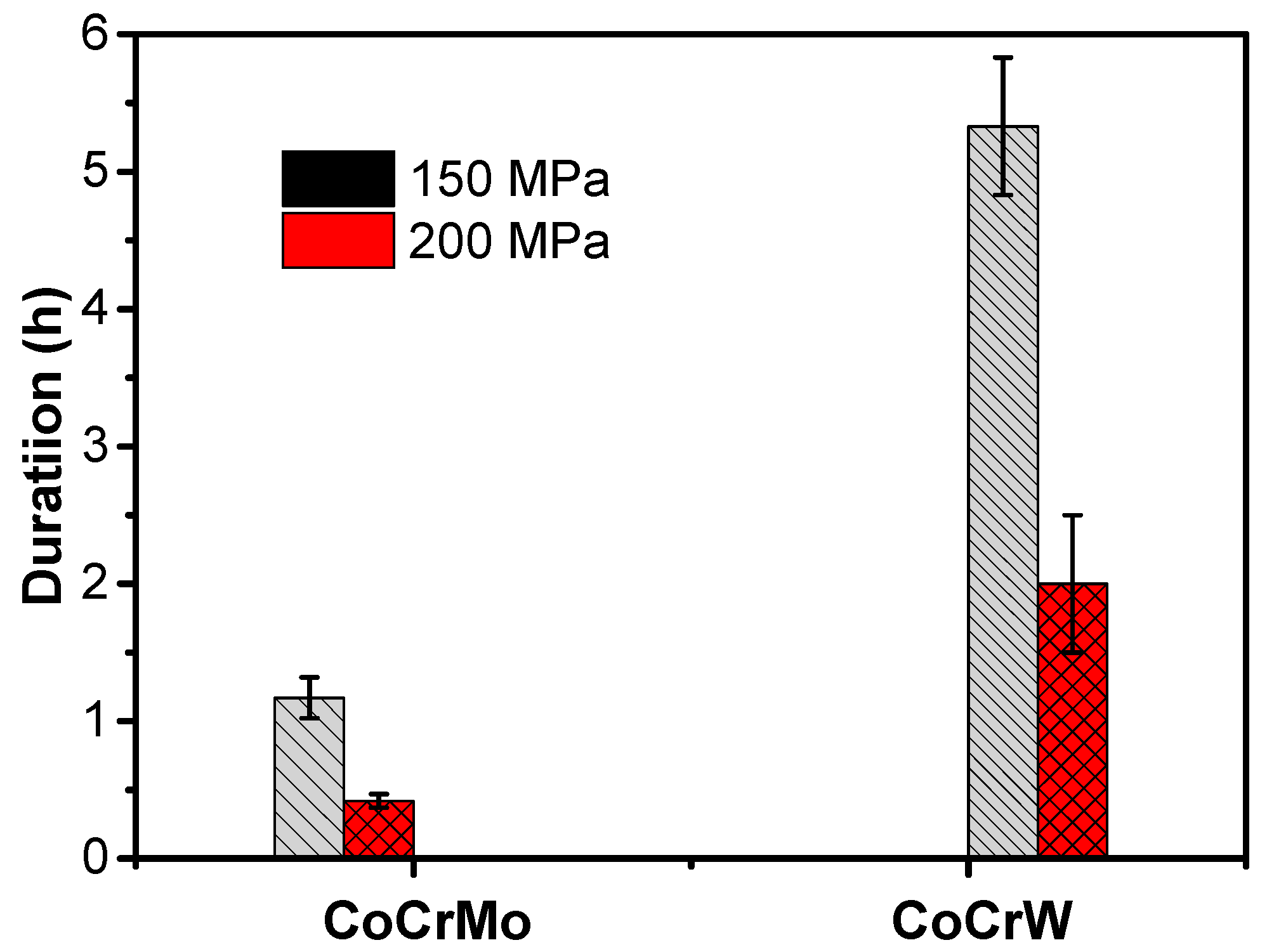
At 900 °C and 150 MPa, the duration of CoCrMo welded specimens was 1.17 h, which was lower than that of CoCrW welded specimens. At 900 °C and 200 MPa, the duration of CoCrMo welded specimens was lower than that of CoCrW welded specimens by 2 h;
(3)
The fatigue life of CoCrMo welded specimens at 900 °C and 220 MPa was lower than the fatigue life of CoCrW welded specimens at 9.432 × 10⁵. The average high-temperature wear rate of CoCrMo specimens was higher than that of CoCrW specimens, indicating that CoCrW was more wear resistant than CoCrMo at 900 °C.

Author Contributions

Methodology, J.M. and G.Z.; Software, X.C.; Investigation, B.C.; Resources, B.Z.; Data curation, T.W.; Writing—original draft, S.H. All authors have read and agreed to the published version of the manuscript.

Funding

This research received no external funding.

Institutional Review Board Statement

Not applicable.

Informed Consent Statement

Not applicable.

Data Availability Statement

Data is contained within the article.

Conflicts of Interest

The authors declare no conflict of interest.

References

  1. Li, J.; Zhong, Z.; Tang, D.; Liu, S.; Wei, P.; Wei, P.; Wu, Z.; Huang, D.; Han, M. A Low-cost second geneution single crystal superalloy DD6. Superalloys 2000, 1, 777–783. [Google Scholar]
  2. Xiong, X.; Quan, D.; Dai, P.; Wang, Z.; Zhang, Q.; Yue, Z. Tensile behavior of nickel-base single-crystal superalloy DD6. Mater. Sci. Eng. A 2015, 636, 608–612. [Google Scholar] [CrossRef]
  3. Wang, Y.; Guo, W.; Xie, Y.; Li, H.; Zeng, C.; Xu, M.; Zhang, H. In-situ monitoring plume, spattering behavior and revealing their relationship with melt flow in laser powder bed fusion of nickel-based superalloy. J. Mater. Sci. Technol. 2024, 177, 44–58. [Google Scholar] [CrossRef]
  4. Song, Y.; Fan, J.; Li, J.; Yang, H.; Yuan, R.; Yu, J.; Ma, X.; Kou, H.; Ren, Z.; Li, J. New insights into the optimisation of the solution heat treatment process and properties of CMSX-4 superalloys. Mater. Sci. Eng. A 2024, 890, 145947. [Google Scholar]
  5. Wang, R.; Wang, J.; Cao, T.; Zhao, R.; Lu, X.; Guan, W.; Tao, H.; Shuai, S.; Songzhe, X.; Xuan, W. Microstructure characteristics of a René N5 Ni-based single-crystal superalloy prepared by laser-directed energy deposition. Addit. Manuf. 2023, 61, 103363. [Google Scholar] [CrossRef]
  6. Zhang, P.; Yuan, Y.; Li, B.; Yang, G.; Song, X. Investigation of tensile deformation mechanisms at room temperature in a new Ni-based single crystal superalloy. Philos. Mag. Lett. 2016, 96, 238–245. [Google Scholar] [CrossRef]
  7. Reimann, L.; Brytan, Z.; Jania, G. Influence of Filler Metal on Electrochemical Characteristics of a Laser-Welded CoCrMoW Alloy Used in Prosthodontics. Materials 2022, 15, 721. [Google Scholar] [CrossRef] [PubMed]
  8. Saha, S.; Grandhi, M.; Kiran, K.U.V.; Liu, Z.; Roy, S. Investigating the effect of select alloying elements in additively manufactured Co-Cr alloy for dental prosthetics. J. Mater. Process. Technol. 2024, 329, 118434. [Google Scholar] [CrossRef]
  9. Günther, K.; Bergmann, J.P.; Suchodoll, D. Hot wire-assisted gas metal arc welding of hypereutectic FeCrC hardfacing alloys: Microstructure and wear properties. Surf. Coat. Technol. 2018, 334, 420–428. [Google Scholar] [CrossRef]
  10. da Silva, M.M.; Batista, V.R.; Maciel, T.M.; dos Santos, M.A.; Brasileiro, T.L. Optimization of submerged arc welding process parameters for overlay welding. Weld. Int. 2018, 32, 122–129. [Google Scholar] [CrossRef]
  11. Dai, W.; Guo, W.; Xiao, J.; Zhu, Y.; Qi, Z.; Shi, J.; Yin, C.; He, D.; Chi, J.; Wan, Z.; et al. Tailoring properties of directed energy deposited Al-Mg alloy by balancing laser shock peening and heat treatment. J. Mater. Sci. Technol. 2024, 203, 78–96. [Google Scholar] [CrossRef]
  12. Xue, J.; Guo, W.; Xia, M.; Zhang, Y.; Tan, C.; Shi, J.; Li, X.; Zhu, Y.; Zhang, H. In-depth understanding in the effect of hydrogen on microstructural evolution, mechanical properties and fracture micro-mechanisms of advanced high-strength steels welded joints. Corros. Sci. 2024, 233, 112112. [Google Scholar] [CrossRef]
  13. Zhang, H.; He, J.; Tang, L.; Zhang, J. High frequency characters of arc light radiation in micro plasma arc welding with pulsed current. Results Phys. 2019, 13, 102259. [Google Scholar] [CrossRef]
  14. Tong, X.; Li, F.-h.; Liu, M.; Dai, M.-j.; Zhou, H. Thermal fatigue resistance of non-smooth cast iron treated by laser cladding with different self-fluxing alloys. Opt. Laser Technol. 2010, 42, 1154–1161. [Google Scholar] [CrossRef]
  15. Kocijan, A.; Milošev, I.; Pihlar, B. Cobalt-based alloys for orthopaedic applications studied by electrochemical and XPS analysis. J. Mater. Sci. Mater. Med. 2004, 15, 643–650. [Google Scholar] [CrossRef] [PubMed]
  16. Herranz, G.; Berges, C.; Naranjo, J.A.; García, C.; Garrido, I. Mechanical performance, corrosion and tribological evaluation of a Co–Cr–Mo alloy processed by MIM for biomedical applications. J. Mech. Behav. Biomed. Mater. 2020, 105, 103706. [Google Scholar] [CrossRef]
  17. Lee, H.W.; Jung, K.-H.; Hwang, S.-K.; Kang, S.-H.; Kim, D.-K. Microstructure and mechanical anisotropy of CoCrW alloy processed by selective laser melting. Mater. Sci. Eng. A 2019, 749, 65–73. [Google Scholar] [CrossRef]
  18. Alvarez-Vera, M.; Hdz-García, H.; Muñoz-Arroyo, R.; Hernandez-Rodriguez, M.; Ortega, J.A.; Mtz-Enriquez, A.; Hernandez-García, F.; Carrera-Espinoza, R.; Ortega-Ramos, I. Wear resistance of surfaced modified CoCr alloy with stellite alloys and boron carbide coating via laser alloying. Wear 2023, 524, 204811. [Google Scholar] [CrossRef]
  19. Frenk, A.; Kurz, W. Microstructural effects on the sliding wear resistance of a cobalt-based alloy. Wear 1994, 174, 81–91. [Google Scholar] [CrossRef]
  20. Amirkhanyan, N.H.; Zakaryan, M.K.; Kharatyan, S.L.; Yeghishyan, A.; Zhukovskyi, M.; Aprahamian, A.; Manukyan, K.V. Stabilization of Metastable γ-Co: Combustion Synthesis and Rapid Processing. Mater. Chem. Phys. 2024, 319, 129368. [Google Scholar] [CrossRef]
  21. Lu, Y.; Guo, S.; Yang, Y.; Liu, Y.; Zhou, Y.; Wu, S.; Zhao, C.; Lin, J. Effect of thermal treatment and fluoride ions on the electrochemical corrosion behavior of selective laser melted CoCrW alloy. J. Alloys Compd. 2018, 730, 552–562. [Google Scholar] [CrossRef]
  22. Shi, Y.; Guo, C.; Li, C.; Du, Z.; Hu, D. Experimental Investigation on Isothermal Sections at 1273 and 1473 K in the Co–Ti–W System. Front. Mater. 2022, 9, 880143. [Google Scholar] [CrossRef]
  23. GBT228.1-2010; Metallic Materials-Tensile Testing Part 1: Method of Test at Room Temperature. China National Standardization Administration: Beijing, China, 2010.
  24. GB/T4338-2006; Aluminium and Aluminium Alloy Corrugated Sheets. China National Standardization Administration: Beijing, China, 2006.
  25. Çelik, A.; Bayrak, Ö.; Alsaran, A.; Kaymaz, İ.; Yetim, A.F. Effects of plasma nitriding on mechanical and tribological properties of CoCrMo alloy. Surf. Coat. Technol. 2008, 202, 2433–2438. [Google Scholar] [CrossRef]
  26. Bang, G.B.; Park, J.H.; Kim, W.R.; Hyun, S.-K.; Park, H.-K.; Lee, T.W.; Kim, H.G. Study on the effect of preheating temperature of SLM process on characteristics of CoCrMo alloy. Mater. Sci. Eng. A 2022, 841, 143020. [Google Scholar]
  27. Wang, X.; Wang, S.; Ren, L.; Wu, W.; Zuo, M.; Xing, W.; Zhang, B.; Fan, W.; He, Z.; Yu, Z. Micro-structure tuning and evolution of hydroxide precursor with radially oriented grains during industrial-scale continuous precipitation process. J. Alloys Compd. 2024, 977, 173458. [Google Scholar]
  28. Zhang, M.; Yang, Y.; Song, C.; Bai, Y.; Xiao, Z. An investigation into the aging behavior of CoCrMo alloys fabricated by selective laser melting. J. Alloys Compd. 2018, 750, 878–886. [Google Scholar]
  29. Wang, D.; Song, C.; Yang, Y.; Bai, Y. Investigation of crystal growth mechanism during selective laser melting and mechanical property characterization of 316L stainless steel parts. Mater. Des. 2016, 100, 291–299. [Google Scholar] [CrossRef]
  30. Bai, Y.; Yang, Y.; Wang, D.; Zhang, M. Influence mechanism of parameters process and mechanical properties evolution mechanism of maraging steel 300 by selective laser melting. Mater. Sci. Eng. A 2017, 703, 116–123. [Google Scholar] [CrossRef]
  31. Sun, S.-H.; Koizumi, Y.; Kurosu, S.; Li, Y.-P.; Matsumoto, H.; Chiba, A. Build direction dependence of microstructure and high-temperature tensile property of Co–Cr–Mo alloy fabricated by electron beam melting. Acta Mater. 2014, 64, 154–168. [Google Scholar] [CrossRef]
  32. Yamanaka, K.; Mori, M.; Koizumi, Y.; Chiba, A. Local strain evolution due to athermal γ → ε martensitic transformation in biomedical CoCrMo alloys. J. Mech. Behav. Biomed. Mater. 2014, 32, 52–61. [Google Scholar] [CrossRef]
  33. Song, X.; Wang, Y.; Zhao, X.; Zhang, J.; Li, Y.; Wang, Y.; Chen, Z. Analysis of carbide transformation in MC-M23C6 and its effect on mechanical properties of Ni-based superalloy. J. Alloys Compd. 2022, 911, 164959. [Google Scholar] [CrossRef]
  34. GB/T 7314-2017; Metallic Materials—Compression Test Method at Room Temperature. China National Standardization Administration: Beijing, China, 2017.
Figure 1. DD6 overlay welding CoCr-based coating: (a) schematic diagram of the structure of wear-resistant coating stacked on the substrate; (b) schematic diagram of microstructure observation of stacked wear-resistant layer; (c) size of endurance performance test specimens.
Coatings 14 00892 g001
Figure 2. Microscopic structure of CoCrMo welding wire. Horizontal observation: (a) low-magnification and (b) high-magnification microstructure; (c) composition analysis. Longitudinal observation: (d) low-magnification and (e) high-magnification microstructure; (f) composition analysis.
Coatings 14 00892 g002
Figure 3. Grain-size analysis of CoCrMo welding wire. Horizontal observation: (a,b) low-magnification microstructure and grain orientation texture; (c) grain-size statistics. Longitudinal observation: (d,e) low-magnification microstructure and grain orientation texture; (f) grain-size statistics.
Coatings 14 00892 g003
Figure 4. Microscopic structure of CoCrW welding wire. Horizontal observation: (a) low-magnification and (b) high-magnification microstructure; (c) composition analysis. Longitudinal observation: (d) low-magnification and (e) high-magnification microstructure; (f) composition analysis.
Coatings 14 00892 g004
Figure 5. Grain size of CoCrW welding wire observed horizontally: (a,b) low-magnification microstructure and grain orientation texture; (c) grain-size statistics.
Coatings 14 00892 g005
Figure 6. Microstructure of CoCrMo overlay welding: (a) fusion zone; (b) enlarged view of fusion zone; (c,d) diffusion layer; (e) heat-affected zone; (f) DD6.
Coatings 14 00892 g006
Figure 7. Microstructure of CoCrW overlay welding: (a) fusion zone; (b) enlarged view of fusion zone; (c,d) diffusion layer; (e) heat-affected zone; (f) DD6.
Coatings 14 00892 g007
Figure 8. Hardness distribution of CoCrMo and CoCrW welded joints.
Coatings 14 00892 g008
Figure 9. (a) Room temperature tensile properties of overlay welded joints; (b) high-temperature tensile properties of overlay welded joints.
Coatings 14 00892 g009
Figure 10. (ac) Room temperature tensile fracture of CoCrMo overlay joint; (df) room temperature tensile fracture of CoCrW overlay joints.
Coatings 14 00892 g010
Figure 11. High-temperature tensile fracture of (ac) CoCrMo overlay joint and (df) CoCrW overlay joints.
Coatings 14 00892 g011
Figure 12. High-temperature compression performance of overlay welded joints: (a) stress–strain curves, (b) compression strength, and (c) modulus of CoCrMo and CoCrW overlay joints.
Coatings 14 00892 g012
Figure 13. High-temperature endurance performance test of overlay welded joints under different stress levels.
Coatings 14 00892 g013
Figure 14. High-temperature persistent fracture: (ac) CoCrMo and (df) CoCrW overlay joint.
Coatings 14 00892 g014
Table 1. The characteristics and applications of several common self-fluxing alloy powders [14].
Alloy TypeMain CategoriesMain CharacteristicsApplication
Fe-based alloyAustenitic stainless steel;
High chromium cast iron
Low cost, but poor oxidation resistance and poor self melting of the alloy.Situations where the requirements are not strict.
Ni-based alloyNi-B-Si series;
Ni-Cr-B-Si series
High wear resistance, good high-temperature stability, corrosion resistance, and high toughness, poor impact resistance, and high-temperature performance is not as good as Co-based alloy powder.Widely used and commonly used for surface welding in severely corrosive medias.
Co-based alloyCo-based wear-resistant alloy;
Co-based high-temperature-resistant alloy;
Co-based corrosion-resistant alloy
The high-temperature resistance is the best, the comprehensive performance of all kinds of surfacing alloys is the best, with high hardness, and wear resistance, impact resistance, corrosion resistance, and oxidation resistance are good, but the price is expensive.Suitable for working at a high temperature of 600~700 °C, with oxidation resistance, corrosion resistance, and wear-resistant surfaces.
Table 2. Main chemical composition (wt.%).
CSiCrMoWFeNiCo
CoCrMo0.083.0~3.816.5~18.527.0~30.0 Bal.
CoCrW0.9~1.4≤2.026.0~32.0≤1.03.0~6.0≤3.0≤3.0Bal.
Table 3. Composition analysis of CoCrMo welding wire (wt.%).
SiMoCrFeCo
Point 12.7113.6522.961.4559.23
Point 24.933.9715.891.0844.16
Point 34.8234.3816.121.0643.62
Point 42.0211.7924.451.6260.12
Table 4. Composition analysis of CoCrW welding wire (wt.%).
CrFeCoNiW
Point 166.151.6727.781.33.11
Point 225.412.6965.142.584.19
Point 344.921.6551.121.330.98
Point 425.792.8164.752.564.09
Table 5. Composition analysis of CoCrMo welding wire (wt.%).
AlSiNbMoCrFeCoNiW
Point 13.391.910.129.8513.430.8833.233.253.97
Point 22.714.370.3914.5512.430.7630.1229.275.4
Table 6. Comparison of fatigue results between CoCrMo and CoCrW welded specimens at 900 ℃, at 220 MPa/ 180 MPa/ 150 MPa.
Stress/MPaCycle Times
CoCrMo2207.186 × 105
CoCrW9.432 × 105
CoCrMo1803.279 × 106
CoCrW1.46 × 106
CoCrMo150>1 × 10⁷
CoCrW>1 × 10⁷
Table 7. Comparison of high-temperature wear of CoCrMo and CoCrW welded specimens.
Frictional FactorWear Volume
(mm3)
Wear Rate
(mm3N−1m−1)
DD60.522 ± 0.099.85 ± 2.49 × 10−35.47 ± 1.38 × 10⁻⁶
CoCrMo0.376 ± 0.076.55 ± 2.35 × 10−33.64 ± 1.31 × 10⁻⁶
CoCrW0.397 ± 0.052.89 ± 0.71 × 10−32.83 ± 1.58 × 10⁻⁶
Disclaimer/Publisher’s Note: The statements, opinions and data contained in all publications are solely those of the individual author(s) and contributor(s) and not of MDPI and/or the editor(s). MDPI and/or the editor(s) disclaim responsibility for any injury to people or property resulting from any ideas, methods, instructions or products referred to in the content.

