Communication

Atomic-Scale Structural and Magnetic Coupling Properties of Twin Boundaries in Lithium Ferrite (Li0.5Fe2.5O4) Film

School of Electronics and Information Engineering, Suzhou Vocational University, Suzhou 215104, China
*
Author to whom correspondence should be addressed.
Coatings 2024, 14(7), 903; https://doi.org/10.3390/coatings14070903
Submission received: 14 June 2024 / Revised: 14 July 2024 / Accepted: 16 July 2024 / Published: 19 July 2024
(This article belongs to the Section Thin Films)

Abstract

:
It is of great academic significance to understand the influence that the atomic-scale structure of interfaces and boundaries within materials has on magnetic coupling characteristics and promote the innovation of advanced magnetic devices. Here, we carried out a systematic investigation of the atomic and electronic structures of twin boundaries (TBs) in Li0.5Fe2.5O4 (LFO) thin films and determined their concurrent magnetic couplings using atomic-resolution transmission electron microscopy and first-principle calculations at the atomic scale. The results show that ferromagnetic or antiferromagnetic coupling can exist across the different TBs in LFO thin films, and electrical structures within a few atomic layers directly rely on the atom arrangement across the TB. Uncovering one-to-one relationships between the magnetic coupling properties of individual TBs and atomic-scale structures can clarify a thorough comprehension of numerous fascinating magnetic properties of commonly utilized magnetic materials, which will undoubtedly encourage the progress of sophisticated magnetic materials and devices.

1. Introduction

A wide range of magnetic properties can be found in spinel ferrites, which have drawn attention due to their potential utilization in sensors, transformers, antennas, high-frequency inductors, microwave devices, and spintronic devices [1]. Magnetic coupling across boundaries in spinel ferrites plays a critical role in both fundamental research significance and magnetic application. For instance, antiphase boundaries (APBs) have been frequently observed in spinel-type ferrite thin films, such as NiFe2O4, Fe3O4, and LFO [2,3,4]. Atomic models and magnetic coupling across APBs have been extensively determined using high-resolution scanning transmission electron microscopy (STEM) and density function theory (DFT) in spinel-type materials [5,6,7]. Antiferromagnetic interactions arise across the APBs, resulting in a larger coercive field for magnetization saturation and increased magnetoresistance within the ferromagnetic film, which can be harmful for applications [8,9,10]. In contrast, engineering the formation of APBs has emerged as a promising approach to effectively modulate the functionality in solid oxide fuel applications [11]. Therefore, it is vital to understand atomic arrangements and magnetic coupling across individual boundaries to tailor the magnetic properties. However, the challenges of simultaneously and accurately determining the atomic structure and magnetic coupling of individual boundaries significantly impede investigations into the relationship between local atomic arrangements and magnetic coupling at boundaries. This is a fascinating but difficult research topic in interface and boundary science.
Besides APBs, it was found that TBs also occur in spinel-type materials, e.g., Fe3O4 and MnAl2O4, which display unusual magnetic characteristics [12,13]. The controllable formation of TBs in spinel lithium manganate helps to obtain a higher rate of performance [14]. In particular, Chen et al. [15] reported on the atomic configuration and magnetic coupling of TBs in Fe3O4 single crystal by combining STEM and the differential phase contrast (DPC) imaging technique, suggesting that the magnetic coupling nature of TBs in Fe3O4, whether ferromagnetic (FM) or antiferromagnetic (AFM), is intimately tied to the atomic configurations at their cores. Specifically, antiferromagnetic interactions can arise across non-stoichiometric TBs. Atomic structure models of TBs have been constructed on the basis of crystallographic relationships and verified experimentally using a high-resolution STEM in LFO films grown on the SrTiO3 (STO) (001) substrate [16]. LFO, as an abundant magnetic material, garners significant interest because of its fascinating electronic and magnetic properties. In defect-free LFO crystal, the magnetic moments of Fe3+ ions interact through super-exchange interactions mediated by oxygen ions, leading to the antiparallel alignment of Fe3+ ion’s magnetic moments on tetrahedral and octahedral sites, which results in the subferromagnetic ground state with a high saturation magnetization of 2.5 μB per formula unit [17,18]. Compared to Fe3O4 materials, non-magnetic Li ions instead of magnetic Fe ions are half occupied at octahedral sites; hence, the magnetic couplings associated with the TBs in LFO film remain unclear.
In the present work, atomic structure configuration and magnetic coupling across TBs in LFO thin film fabricated on the STO (001) substrate were probed by combining high-resolution STEM imaging techniques and first-principle calculations, demonstrating how the nature of magnetic coupling across TBs can vary between antiferromagnetic and ferromagnetic coupling, contingent upon the atomic structures and resulting electronic configurations of the TBs.

2. Materials and Methods

Materials and TEM/STEM experiments: The LFO ceramic target for film growth was prepared by a standard solid-state reaction method with the initial reactants Fe2O3 and LiCO3 using a molar ratio of 5:2 for Fe2O3 and LiCO3, respectively [19]. The LFO films were deposited on single-crystalline (001)-oriented STO substrates using a high-pressure sputtering system at a substrate temperature of 800 °C and in an ambient atmosphere consisting of Ar and O2 at a 1:1 ratio with a pressure of 0.5 mbar. To facilitate TEM/STEM analysis, cross-sectional lamella specimens were produced via the focused ion beam (FIB) lift-out technique using an FEI Helios600i Dualbeam system (Thermo Fisher Scientific, Waltham, MA, USA), and the flowchart photo of TEM /STEM sample preparation by the instrument is shown in Supplementary Figure S1. The lamellae were sectioned in STO <110> crystallographic directions. Bright-field (BF) TEM images and selected-area electron diffraction (SAED) patterns were acquired using a JEOL JEM-2100 microscope. Atomic-resolution high-angle annular dark field (HAADF) and annular bright field (ABF) imaging were carried out on a JEOL ARM200F (JEOL Ltd., Tokyo, Japan), and the specific parameters attributed to HAADF and ABF STEM imaging are documented in our previous research [16].
HAADF and ABF image simulation: The HAADF STEM images were simulated using the abTEM package with the PRISM algorithm [20]. The electron energy was set at 200 keV, the radial cutoff of the plane-wave expansion was set as 30 mrad, and the defocus parameter was 30 Å. The detector angles for HAADF and ABF image simulations were 70–180 mrad and 12–24 mrad, respectively, and the other parameters for ABF image simulation were identical to those for HAADF image simulation.
The calculation for DFT: Density functional theory calculations were performed using the projector augmented plane-wave (PAW) basis set, implemented within the Vienna ab initio simulation package (VASP) [21]. And the plane waves were cut off at 400 eV. The exchange-correlation effects of electrons were modeled using the generalized gradient approximation (GGA), as proposed by Perdew, Burke, and Ernzerhof [22]. The energy convergence criterion for solving the self-consistent Kohn–Sham equations was set at 10−5 eV. The Brillouin zone was sampled using the Monkhorst-Pack scheme with a resolution finer than 0.03 Å−1 [23]. To enhance the modeling of strong electron–electron interactions within d-shells, we employed the DFT + U approach [24], setting Ueff = 3.8 eV for the d-shells of Fe ion. All structures considered in this study were fully relaxed until a Hellman–Feynman value less than 0.05 eV/Å was obtained. The formation energy of twin boundaries is defined as follows [15]:
E f = 1 2 A ( E T B n O μ O n F e μ F e n L i μ L i )
where ETB is the total energy of the supercell model with two identical twin boundaries, nO, nFe, and nLi are the quantities of O, Fe, and Li ions in the supercell model, μFe and μLi denote the chemical potentials of Fe and Li ions, respectively, defined as the energy per atom in pure metal body-centered crystals, μO is the chemical potential of O ions and is calculated via the Equation 8μO + 5μFe + μLi = μ(LiFe5O8) in which μ(LiFe5O8) is the energy of the cell of Li-doped Fe3O4, and A denotes the area of each twin boundary.

3. Results and Discussions

Figure 1a displays the low magnification bright field TEM images of LFO thin film with a thickness of 30 nm, showing a cross-sectional overview of the LFO/STO (001) heterosystem. The contrast difference between the film and substrate is clearly visible, and the interface between the film and substrate is indicated by a horizontal arrow. The oblique contrast lines indicated by the yellow arrow are discerned in the film, and the contrasting lines result from the twin boundaries situated in the (111) habit plane.
Figure 1b displays the typical diffraction patterns covering the LFO film and part of the STO substrate recorded along the [1 1 ¯ 0] zone of the axis of STO. The diffraction pattern of the STO substrate is marked by a solid white rectangle, and the diffraction patterns marked by a solid yellow and dashed yellow rectangle have a 70.5° rotation, which results from the LFO matrix region and twin domain area, respectively. The film–substrate orientation relationship in LFO matrix regions is represented by [1 1 ¯ 0](001)film//[1 1 ¯ 0](001)substrate. The results of diffraction patterns also confirm that the twin boundaries form in the LFO film. It was observed that the reflection spots split between film and substrate along the in-plane and out-of-plane, indicating that misfit strain relaxation occurs. Using the lattice parameter of the STO substrate (0.3905 nm) [25] as the calibration standard, we determined the in-plane and out-of-plane lattice parameters of the film to be 0.8301 nm and 0.8359 nm, respectively.
High-resolution STEM experiments were conducted in order to definitively discern the atomic structure of TBs viewed along [1 1 ¯ 0] the zone of the axis of the STO substrate. Numerous STEM measurements show the simultaneous presence of three distinct types of TBs in the LFO film. Figure 2 displays three groups of STEM-HAADF and ABF images of TBs; Figure 2a,b show the HAADF image and ABF image of TB I, indicated by green arrows; and Figure 2c,d display the HAADF image and ABF image of TB II, indicated by blue arrows; also, Figure 2e,f show the HAADF image and ABF image of TB III, indicated by red arrows. The film was separated into domain I and domain II by the TBs. It was found that domains I and II display a reflection symmetry across the TB I in Figure 2a, indicated by orange dashed lines. On the contrary, domains I and II, separated by either a TB II or a TB III, exhibit a combination of a glide transformation and reflection symmetry, which is also indicated by orange dashed lines in Figure 2b,c. Based on the STEM-HAADF imaging principle, the intensity in the HAADF image directly correlates with the atomic number (Z) [26]; as a result, the heavier atoms appear brighter, and, additionally, the higher atomic density also generates a brighter contrast. Only the Fe atomic columns are visible in the HAADF images in Figure 2, while oxygen columns remain undetectable due to significantly weaker scattering. The contrast variation in cation columns arises from the varying density of Fe atoms in [1 1 ¯ 0] the projection direction. It is clear that the cation arrangement of TB I is symmetric, in contrast with those of TB II and TB III, which are asymmetric, and the three types of TBs all lie in (111) habit planes. Remarkably, TB III presents cation deficiency, which induces intensity variation in the atomic columns, as marked by a red arrow in Figure 2e. The white arrow demonstrates the atomic column with cation deficiency in Figure 2e.
Figure 2b,d,f display ABF images of three types of TBs, which were acquired simultaneously alongside their corresponding HAADF image to immediately resolve O atom columns. According to ABF images, the oxygen sublattices in three types of TBs appear a feature of ∑3[111] coherent TBs. In particular, the planes between twin domains, namely TBs, lie at the O atom plane marked by green, blue, and red arrows, respectively. Different cation arrangements within the O sublattices lead to the formation of three distinct types of TBs.
To identify the magnetic properties of three types of TBs, DFT computations were performed. On the basis of the experimental STEM images, the potential candidate atomic models of TBs were established, and the most energetically stable atomic structures were acquired in which formation energy was adopted. The formation energies for TB I, TB II, and TB III were determined to be 1.67 J/m2, 0.75 J/m2, and 2.80 J/m2, respectively. However, TB III was frequently observed in the LFO film, which is contradictory to the calculated formation energy. In fact, the APBs also form in the LFO film, and APBs interact with TB I and TB II, further generating abundant TB III., which have been frequently observed in previous work [16]. The density distribution of the three types of TBs is different from that in Fe3O4 single crystals [15]. The lowest-energy optimal atomic configuration after relaxation is shown in Figure 3a,c,e; STEM simulations were undertaken by the use of the relaxed atomic models displayed in Figure 3b,d,f, which match well with the experimental counterparts.
In order to identify the magnetic configuration that is the most stable for each type of TB, we compared the energy of the FM and AFM coupling configurations. The results indicate how TB I prefers to configure AFM coupling across the boundary with an interface formation energy 0.39 J/m2 lower than that of FM coupling. Also, TB II configures preferably as AFM coupling across the boundary with interface formation energy 0.47 J/m2 lower than that of FM coupling. In contrast, TB III typically develops FM couplings across boundaries with an interface formation energy −0.06 J/m2 lower than that of AFM coupling. The weak FM coupling at TB III is likely to result from the Fe cation deficiency, which leads to the decreased density of super-exchange interactions between cations via oxygen [27]. The results of formation energy for TBs, exchange coupling energy, and the magnetic coupling of three types of TBs are summarized and presented in Table 1.
The results of the spin-polarized density of states (DOS) provide additional evidence of these magnetic coupling for TBs, as shown in Figure 4. The LFO film was separated by the TBs as domain I, shaded by transparent yellow, and domain II, shaded by transparent blue, and the spin-polarized DOSs for domain I and domain II are plotted in the left and right part in Figure 4a–c. As shown in Figure 4a, the spin polarization flips direction across the boundary planes of TB I, which suggests AFM coupling between two twin domains separated by TB I. The same situation appears in Figure 4b, demonstrating the AFM coupling nature at TB II. In contrast to the DOS results of TB I and II, the spin polarization remains in the same direction across the boundary plane of TB III in Figure 4c. Noticeably, the spin-polarized DOS at the three different types of TBs is directly depicted in Supplementary Figure S2; spin polarization eventually inverts over the core area of TB I and II, revealing their AFM coupling nature, while the direction of spin polarization remains unaltered across the core area of TB III, and consistent with its FM coupling characteristics.
The atomic structures of three types of TBs in the LFO film are similar to that of the Fe3O4 crystal, whereas magnetic couplings across the TBs are quite different from the results in Fe3O4 crystal, where TB I and II both exhibit FM coupling and TB III undergoes AFM coupling [15]. It is recognized that in the spinel structure AB2O4, the magnetic spins align in an antiparallel manner between the tetrahedral and octahedral sites. Concerning magnetic coupling, depending on the super-exchange interaction via cation-oxygen-cation, the bond angle should be considered. For the case of TBs in LFO films, the bond angles of 131.6°, 133.5°, and 89.7° between A-O-B atoms dominate across TB I, TB II, and TBIII, respectively, when acquired from relaxed atomic models. Particularly, for B-site Li ions, which are not magnetic ions in LFO, the B-site occupation of Li ions at TB I and II is inclined to decrease FM exchange interactions between B-O-B atoms, which may result in AFM coupling across TB I and II. On the contrary, Fe deficiency exists at TB III, and the antiferromagnetic super-exchange interactions between A-O-B atoms decrease, which results in weak FM coupling dominated at TB III. In the present work, we anticipated the ferromagnetic or antiferromagnetic coupling of TBs in LFO film by first-principle calculations; furthermore, the experimental evidence to directly support magnetic coupling will be provided in future work to verify the DFT results. The occurrence of TBs with AFM coupling will weaken the saturation magnetization of the film, and the pinning of the magnetic domain walls effect induced by those antiferromagnetic TBs are likely to arise in the LFO film, resulting in a larger coercive field in the film [28]. Also, the presence and density of antiferromagnetic TBs can manipulate the effective magnetic anisotropy of magnetic film. In contrast, the TBs with ferromagnetic coupling do not decrease the spin polarization of the film [7,29]. Taking into account the magnetic coupling nature occurring across TBs in LFO film, the nano-scale TBs present intriguing prospects for utilization in advanced nano-spintronic devices, such as spin torque magnetic random-access memory.

4. Conclusions

In conclusion, understanding the interaction mechanisms of atomic structure and magnetic coupling is crucial for the field of materials science. By combining atomic-resolution STEM measurements and atomistic first-principles computations, we successfully determined the atomic structure and magnetic coupling of different TBs in LFO films. It was discovered that three types of TBs form in the LFO/STO film system, which exhibit a different atomic core structure. The atomic core structure of TBs directly affects whether the magnetic coupling across the TBs is antiferromagnetic or ferromagnetic. DFT results indicate that magnetic couplings across TB I and TB II are antiferromagnetic and that across TB III exhibit ferromagnetic. Revealing the nature of magnetic coupling across grain boundaries, as well as material interfaces can help with the development of improved magnetic materials and technologies.

Supplementary Materials

The following supporting information can be downloaded at https://www.mdpi.com/article/10.3390/coatings14070903/s1. Figure S1. The flowchart of TEM sample preparation by focus ion beam (FIB)/scan electron microscope (SEM) dual beam system; Figure S2. Spin-polarized DOS directly at the TBs. The spin polarization gradually inverts the direction across the core regions of TB I and TB II in (a) and (b), verifying their AFM coupling. The direction of spin polarization maintains unchanged across the core region of TB III in (c), indicating a FM coupling nature.

Author Contributions

Conceptualization, K.L.; investigation, K.L. and S.Z.; writing—original draft preparation, K.L.; writing—review and editing, J.L. and S.Z.; supervision, J.L. All authors have read and agreed to the published version of the manuscript.

Funding

This research was funded by the Natural Science Foundation of the Jiangsu Higher Education Institutions of China (Grant: 23KJB510032), the Enterprise Practice of Young Teachers in Vocational Colleges in Jiangsu Province (2024QYSJ088), the Cultivation Project of Suzhou Vocational University (SVU2021py02), the Science and Technology Planning Project of Suzhou City (No. SZS2022015) and Project for constructing an excellent teaching team by“Qing Lan Project”of the Education Department of Jiangsu Province (2023).

Institutional Review Board Statement

Not applicable.

Informed Consent Statement

Not applicable.

Data Availability Statement

Data are contained within the article and Supplementary Materials.

Conflicts of Interest

The authors declare no conflicts of interest.

References

  1. Sanchez-Lievanos, K.R.; Stair, J.L.; Knowles, K.E. Cation Distribution in Spinel Ferrite Nanocrystals: Characterization, Impact on their Physical Properties, and Opportunities for Synthetic Control. Inorg. Chem. 2021, 60, 4291–4305. [Google Scholar] [CrossRef]
  2. McKenna, K.P.; Hofer, F.; Gilks, D.; Lazarov, V.K.; Chen, C.; Wang, Z.; Ikuhara, Y. Atomic-scale Structure and Properties of Highly Stable Antiphase Boundary Defects in Fe3O4. Nat. Commun. 2014, 5, 5740. [Google Scholar] [CrossRef] [PubMed]
  3. Mi, S.B.; Zhang, R.Y.; Lu, L.; Liu, M.; Wang, H.; Jia, C.L. Atomic-scale Structure and Formation of Antiphase Boundaries in α-Li0.5Fe2.5O4 Thin Films on MgAl2O4(001) Substrates. Acta Mater. 2017, 127, 178–184. [Google Scholar] [CrossRef]
  4. Singh, A.V.; Khodadadi, B.; Mohammadi, J.B.; Keshavarz, S.; Mewes, T.; Negi, D.S.; Datta, R.; Galazka, Z.; Uecker, R.; Gupta, A. Bulk Single Crystal-Like Structural and Magnetic Characteristics of Epitaxial Spinel Ferrite Thin Films with Elimination of Antiphase Boundaries. Adv. Mater. 2017, 29, 1701222. [Google Scholar] [CrossRef] [PubMed]
  5. Liu, X.; Wu, M.; Qu, K.; Gao, P.; Mi, W. Atomic-Scale Mechanism of Grain Boundary Effects on the Magnetic and Transport Properties of Fe3O4 Bicrystal Films. ACS Appl. Mater. Interfaces 2021, 13, 6889–6896. [Google Scholar] [CrossRef] [PubMed]
  6. Li, Z.; Lu, J.; Jin, L.; Rusz, J.; Kocevski, V.; Yanagihara, H.; Kita, E.; Mayer, J.; Dunin-Borkowski, R.E.; Xiang, H.; et al. Atomic Structure and Electron Magnetic Circular Dichroism of Individual Rock Salt Structure Antiphase Boundaries in Spinel Ferrites. Adv. Funct. Mater. 2021, 31, 2008306. [Google Scholar] [CrossRef]
  7. Gao, C.; Jiang, Y.; Yao, T.; Tao, A.; Yan, X.; Li, X.; Chen, C.; Ma, X.-L.; Ye, H. Atomic Origin of Magnetic Coupling of Antiphase Boundaries in Magnetite Thin films. J. Mater. Sci. Technol. 2022, 107, 92–99. [Google Scholar] [CrossRef]
  8. Margulies, D.T.; Parker, F.T.; Rudee, M.L.; Spada, F.E.; Chapman, J.N.; Aitchison, P.R.; Berkowitz, A.E. Origin of the Anomalous Magnetic Behavior in Single Crystal Fe3O4 Films. Phys. Rev. Lett. 1997, 79, 5162. [Google Scholar] [CrossRef]
  9. Xu, K.; Lin, T.; Rao, Y.; Wang, Z.; Yang, Q.; Zhang, H.; Zhu, J. Direct Investigation of the Atomic Structure and Decreased Magnetism of Antiphase Boundaries in Garnet. Nat. Commun. 2022, 13, 3206. [Google Scholar] [CrossRef]
  10. Wu, H.C.; Abid, M.; Chun, B.S.; Ramos, R.; Mryasov, O.N.; Shvets, I.V. Probing One Antiferromagnetic Antiphase Boundary and Single Magnetite Domain Using Nanogap Contacts. Nano Lett. 2010, 10, 1132–1136. [Google Scholar] [CrossRef]
  11. Xu, K.; Hung, S.-W.; Si, W.; Wu, Y.; Huo, C.; Yu, P.; Zhong, X.; Zhu, J. Topotactically Transformable Antiphase Boundaries with Enhanced Ionic Conductivity. Nat. Commun. 2023, 14, 7382. [Google Scholar] [CrossRef] [PubMed]
  12. Leung, G.W.; Vickers, M.E.; Yu, R.; Blamire, M.G. Epitaxial Growth of Fe3O4 (111) on SrTiO3 (001) Substrates. J. Cryst. Growth 2008, 310, 5282–5286. [Google Scholar] [CrossRef]
  13. Lee, D.; Trang, T.T.T.; Heo, Y.-U. Role of Dislocation Climb on Twin Boundary and Antiphase Boundary Formations in Inverse-Spinel MnAl2O4. J. Alloy Compd. 2023, 958, 170526. [Google Scholar] [CrossRef]
  14. Guo, Z.; Jiang, H.; Sun, X.; Li, X.; Liu, Z.; Zhang, J.; Luo, J.; Zhang, J.; Tao, X.S.; Ding, J.; et al. Ultrafast Non-Equilibrium Phase Transition Induced Twin Boundaries of Spinel Lithium Manganate. Adv. Energy Mater. 2024, 14, 2302484. [Google Scholar] [CrossRef]
  15. Chen, C.; Li, H.; Seki, T.; Yin, D.; Sanchez-Santolino, G.; Inoue, K.; Shibata, N.; Ikuhara, Y. Direct Determination of Atomic Structure and Magnetic Coupling of Magnetite Twin Boundaries. ACS Nano 2018, 12, 2662–2668. [Google Scholar] [CrossRef] [PubMed]
  16. Liu, K.; Zhang, R.; Lu, L.; Mi, S.; Liu, M.; Wang, H.; Wu, S.; Jia, C. Atomic-scale Investigation of Spinel LiFe5O8 Thin Films on SrTiO3 (001) Substrates. J. Mater. Sci. Technol. 2020, 40, 31–38. [Google Scholar] [CrossRef]
  17. Dehghani Dastjerdi, O.; Shokrollahi, H.; Mirshekari, S. A Review of Synthesis, Characterization, and Magnetic Properties of Soft Spinel Ferrites. Inorg. Chem. Commun. 2023, 153, 110797. [Google Scholar] [CrossRef]
  18. Kim, S.Y.; Kim, K.S.; Jong, U.G.; Kang, C.J.; Ri, S.C.; Yu, C.J. First-principles Study on Structural, Electronic, Magnetic and Thermodynamic Properties of Lithium Ferrite LiFe5O8. RSC Adv. 2022, 12, 15973–15979. [Google Scholar] [CrossRef] [PubMed]
  19. Zhang, R.; Liu, M.; Lu, L.; Mi, S.-B.; Wang, H. Strain-tunable Magnetic Properties of Epitaxial Lithium Ferrite Thin Film on MgAl2O4 Substrates. J. Mater. Chem. C 2015, 3, 5598–5602. [Google Scholar] [CrossRef]
  20. Madsen, J.; Susi, T. The abTEM code: Transmission Electron Microscopy from First Principles. Open Res. Eur. 2021, 1, 24. [Google Scholar] [CrossRef]
  21. Kresse, G.; Joubert, D. From Ultrasoft Pseudopotentials to the Projector Augmented-wave Method. Phys. Rev. B 1999, 59, 1758–1775. [Google Scholar] [CrossRef]
  22. Perdew, J.P.; Burke, K.; Ernzerhof, M. Generalized Gradient Approximation Made Simple. Phys. Rev. Lett. 1996, 77, 3865–3868. [Google Scholar] [CrossRef] [PubMed]
  23. Chadi, D.J. Special Points for Brillouin-zone Integrations. Phys. Rev. B 1977, 16, 1746–1747. [Google Scholar] [CrossRef]
  24. Anisimov, V.I.; Zaanen, J.; Andersen, O.K. Band Theory and Mott insulators: Hubbard U instead of Stoner I. Phys. Rev. B 1991, 44, 943. [Google Scholar] [CrossRef] [PubMed]
  25. Howard, S.A.; Yau, J.K.; Anderson, H.U. Structural Characteristics of Sr1−xLaxTi3+δ as a Function of Oxygen Partial Pressure at 1400 °C. J. Appl. Phys. 1989, 65, 1492–1498. [Google Scholar] [CrossRef]
  26. Pennycook, S.J.; Boatner, L.A. Chemically Sensitive Structure-imaging with a Scanning Transmission Electron microscope. Nature 1988, 336, 565–567. [Google Scholar] [CrossRef]
  27. Desai, H.B.; Tanna, A.R. Effect of Substitution on the Electric and Magnetic Properties of Ferrites. In Ferrites and Multiferroics: Engineering Materials; Bhargava, G.K., Bhardwaj, S., Singh, M., Batoo, K.M., Eds.; Springer: Singapore, 2021. [Google Scholar]
  28. Liu, K.; Zhang, R.; Lu, L.; Li, J.; Zhang, S. Effect of Film Thickness on Microstructural and Magnetic Properties of Lithium Ferrite Films Prepared on Strontium Titanate (001) Substrates. Coatings 2023, 13, 2097. [Google Scholar] [CrossRef]
  29. Vronka, M.; Straka, L.; Graef, M.D.; Heczko, O. Antiphase Boundaries, Magnetic Domains, and Magnetic Vortices in Ni–Mn–Ga Single Crystals. Acta Mater. 2020, 184, 179–186. [Google Scholar] [CrossRef]
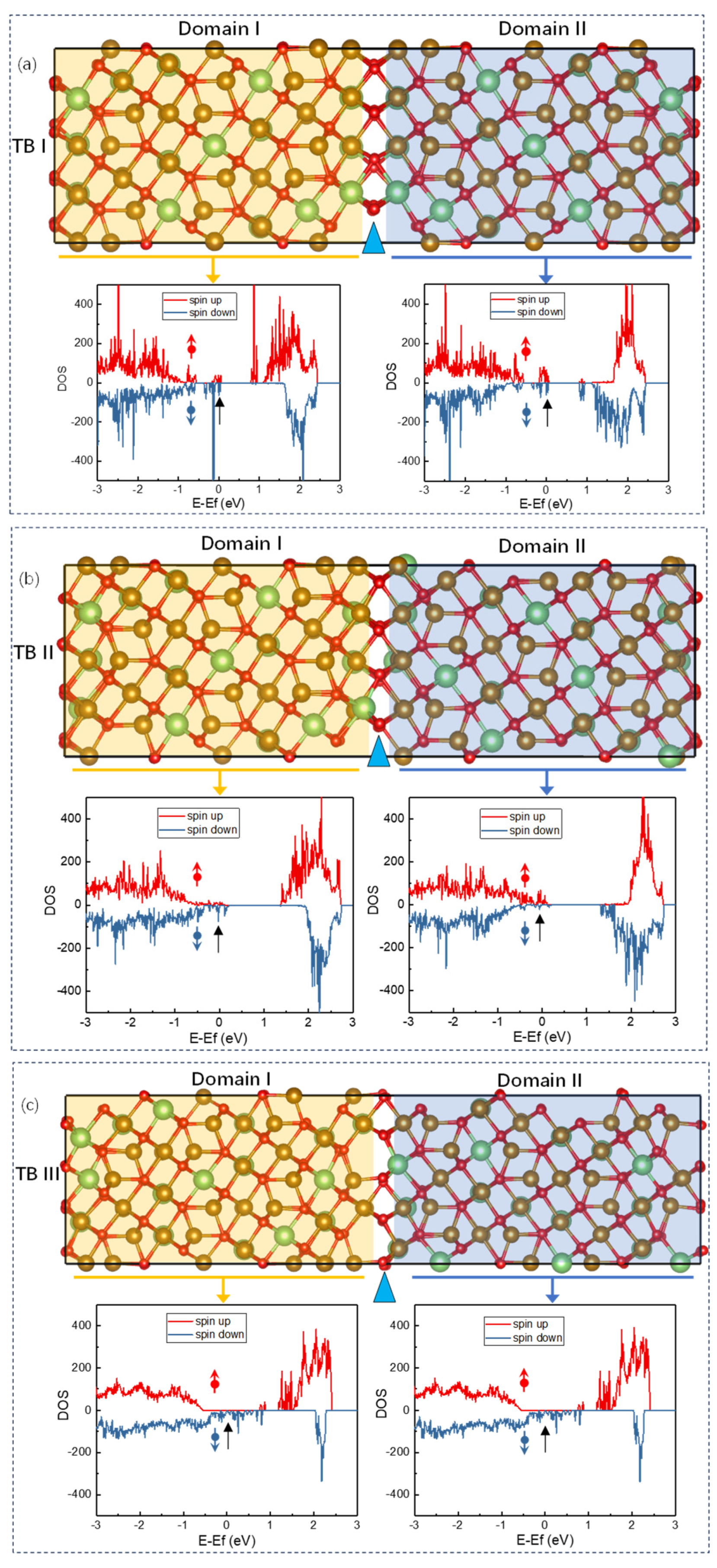
Figure 1. (a) BF-TEM images of LFO film with a thickness of 30 nm on the STO (001) substrate. The interface between film and substrate is denoted by a black horizontal arrow. (b) The SAED patterns of the LFO/STO (001) heterosystem were typically recorded along the [1 1 ¯ 0] STO zone axes. The separation of the reflection spots was marked by a white oblique arrow.
Coatings 14 00903 g001
Figure 2. Clarifying the atomic structure configuration of three types of TBs from the projection along the [1 1 ¯ 0] direction. (a,c,e) High-resolution HAADF images displaying atomic structures of TB I, TB II, and TB III, respectively. (b,d,f) Corresponding ABF images capturing atomic structures of these three types of TBs acquired simultaneously with the HAADF images and uncovering all the atomic columns present at the TBs, including O columns. The white solid circles in (e,f) represent Fe vacancies.
Coatings 14 00903 g002
Figure 3. (a,c,e) The optimized atomic models of TB I, TB II, and TB III and the vertical blue arrows denote the boundaries of TBs. The brown, green, and red balls represent the Fe ions, Li ions, and oxygen ions, respectively. (b,d,f) Simulated HAADF STEM images of three types of TBs along the [1 1 ¯ 0] zone of the axis. HAADF STEM images displaying atomic structures of TB I, TB II, and TB III, respectively. The vertical blue arrows indicate the boundary of three types of TBs, respectively, and in (f) the yellow circles denote Fe deficiencies at the boundary of TB III.
Coatings 14 00903 g003
Figure 4. Spin-polarized DOS plots of TB I (a), TB II (b), and TB III (c);The black arrow denotes the EF, and the red and dark blue arrows represent spin-up and spin-down states on the DOS plot.The atoms within and near the boundary are indicated by colored shading. The relaxed atomistic models are also given for reference, and the vertical blue arrows denote the boundary of three types of TBs, respectively.
Coatings 14 00903 g004
Table 1. Formation energy, exchange coupling energy and magnetic coupling of TBI, TB II, and TB III.
Type of TBsFormation Energy
(J/m2)
Exchange Coupling Energy
(EFM-EAFM) (J/m2)
Magnetic Coupling
TB I1.670.39AFM
TB II0.750.47AFM
TB III2.80−0.06FM
Disclaimer/Publisher’s Note: The statements, opinions and data contained in all publications are solely those of the individual author(s) and contributor(s) and not of MDPI and/or the editor(s). MDPI and/or the editor(s) disclaim responsibility for any injury to people or property resulting from any ideas, methods, instructions or products referred to in the content.

