Article

Preparation of CrCoFeNiMn High-Entropy Alloy Coatings Using Gas Atomization and Laser Cladding: An Investigation of Microstructure, Mechanical Properties, and Wear Resistance

School of Mechanical Engineering, Yancheng Institute of Technology, Yancheng 224051, China
*
Authors to whom correspondence should be addressed.
Coatings 2024, 14(7), 906; https://doi.org/10.3390/coatings14070906
Submission received: 17 June 2024 / Revised: 16 July 2024 / Accepted: 17 July 2024 / Published: 19 July 2024
(This article belongs to the Special Issue Laser Surface Modifications and Additive Manufacturing)

Abstract

:
In this study, a spherical CrCoFeNiMn high-entropy alloy (HEA) powder with uniform size was prepared using gas atomization. High-quality CrCoFeNiMn HEA coatings were then applied to a 316L stainless steel substrate using prepowdered laser cladding. The main focus of the study is on the phase structure composition and stability, microstructure evolution mechanism, mechanical properties, and wear resistance of CrCoFeNiMn HEA coatings. The results show that the CrCoFeNiMn HEA coatings prepared using gas atomization and laser melting techniques have a single FCC phase structure with a stable phase composition. The coatings had significantly higher diffraction peak intensities than the prepared HEA powders. The coating showed an evolution of columnar and equiaxed crystals, as well as twinned dislocation structures. Simultaneously, the microstructure transitions from large-angle grain boundaries to small-angle grain boundaries, resulting in a significant refinement of the grain structure. The CrCoFeNiMn HEA coating exhibits excellent mechanical properties. The microhardness of the coating increased by 66.06% when compared to the substrate, the maximum wear depth was reduced by 65.59%, and the average coefficient of friction decreased by 9.71%. These improvements are mainly attributed to the synergistic effects of grain boundary strengthening, fine grain strengthening, and twinning and dislocation strengthening within the coating.

Graphical Abstract

1. Introduction

High-entropy alloys (HEAs) are usually developed by alloying five or more elements in equal atomic ratios [1,2]. Because of their unique atomic structure and high mixing entropy, HEAs internally exhibit solid solution structures such as face-centered cubic, body-centered cubic, and densely arranged hexagonal. HEAs have excellent properties due to their unique physical phases and atomic structures [3,4,5]. Among the many HEAs, the CrCoFeNiMn HEA has received a lot of attention because of its good mechanical properties [6]. The CrCoFeNiMn HEA has a typical face-centered cubic (FCC) structure. CrCoFeNiMn HEA coatings have excellent plastic deformation properties and can be adapted to various surface shapes, while their stable solid solution structure gives them good abrasion resistance, making them valuable for use in aerospace, nuclear energy, and automotive fields [7,8,9]. Because of its low cost and ease of machining and molding, 316L stainless steel material is commonly used to manufacture important structural components in hydraulic and automotive transmission systems [10]. In the actual working environment, impurity particles such as dust and grit can contaminate transmission components, causing scratches, wear, and other forms of failure [11]. Combining the CrCoFeNiMn HEA coating, known for its good mechanical properties and process adaptability, with the low-cost 316L stainless steel material can effectively extend the working life of 316L stainless steel parts and enhance the application potential of the CrCoFeNiMn HEA.
In recent years, researchers have attempted to prepare HEA coatings using laser cladding [12,13,14]. Laser cladding is a process in which the surface of a material is instantaneously heated and melted using a high-energy laser beam to optimize the surface structure of the material [15,16]. Eun Seong Kim et al. used laser cladding to prepare a CrCoFeNiMn HEA coating on the surface of 304 stainless steel. Their study showed that the coating had excellent wear resistance and corrosion resistance [17]. He Rui et al. used laser cladding to prepare HEA coatings of FeCrNiMnAl with different laser energy densities on 17-4 PH stainless steel and illustrated the three-body wear mechanism of FeCrNiMnAl coatings [18]. Yuanzhuo Liu used laser cladding to successfully prepare defect-free CrCo-Ni, CrCoNi-TiC, and CrCoNi-SiC coatings on the surface of alloy IN718 [19]. The properties of spherical powder, including sphericity, fluidity, and particle size distribution, have a significant impact on the microstructure and mechanical properties of the final coating during the laser cladding process [20,21]. Therefore, producing spherical HEA powders with appropriate particle sizes for practical applications is a matter of concern.
The three main methods for producing powder are gas atomization, mechanical alloying, and electrochemical deposition. Among these, the gas atomization method, which combines high production efficiency and good molding quality, has become the standard process for preparing HEA powder. Researchers have utilized gas atomization to prepare high-entropy alloy powders such as CrCoFeNIAl, AlCoCrCuFeNiSi, CrCoFeNiTi, etc. [22,23,24,25,26]. Additionally, they have produced high-entropy alloys with excellent properties by combining hot-press sintering and plasma sintering processes. However, there are certain issues with HEAs produced by sintering, including surface defects such as pores, cracks, and incomplete powder melting [27,28]. Laser cladding technology effectively addresses these issues associated with traditional sintering processes. Currently, there is limited research on the preparation of HEA coatings by combining the gas atomization method with laser cladding. This study focuses on preparing high-performance CrCoFeNiMn HEA coatings on the surface of a 316L stainless steel substrate through a combination of the gas atomization method and the pre-powdered laser cladding process. This study investigates the microstructural evolution process, mechanical properties, and wear resistance of the HEA coatings, as well as the reinforcement strengthening mechanism.

2. Materials and Methods

2.1. Materials Preparation

The CrCoFeNiMn HEA powder utilized in this experiment was obtained from Nanjing Mingchang New Material Technology Co., Ltd. Nanjing, China, The metal powders were first melted in a vacuum induction furnace (VS-300RP) under a protective argon atmosphere. Subsequently, argon was used for atomization; the pressure was set at 3.5 MPa, with an argon flow rate of 7 L/min, and the oxygen content of the gas atomization powder was as low as 132 ppm (mg/kg). The atomization equipment was tightly sealed to prevent oxygen ingress. CrCoFeNiMn HEA powder with particle sizes ranging from 8.6 µm to 24.6 µm is produced using a rapid cooling system. The chemical analysis of the HEA powder, as shown in Table 1, reveals a uniform element distribution and a balanced composition. The 316L stainless steel sheets were prepared via a casting process and sourced from Nanjing Tengyao Stainless Steel Co., Ltd., Nanjing, China, with an initial surface roughness of Ra 0.3 μm. The surface of the 316L stainless steel substrate was cleaned with alcohol to ensure the removal of any oil and other contaminants. Sandpaper was used to remove the oxide layer and impurities from the substrate surface. A high-quality CrCoFeNiMn with HEA coating was then prepared using a laser machine (HQ2000-FT1, Da heng Laser Technology Co., Ltd. Nanjing, China) under rapid scanning conditions. The experimental procedure is illustrated in Figure 1 Based on researchers’ experimental experience, laser powers ranging from 1200 W to 1500 W, scan speeds from 4 mm/s to 8 mm/s, and an overlap rate of 40% can effectively melt CrCoFeNiMn powder and form a dense coating [29,30]. After multiple experiments and an observation of coating quality, we ultimately chose a laser power of 1300 W, a scan speed of 6 mm/s, and an overlap rate of 40%. To prevent oxidation of the molten metal, argon gas was used as a protective atmosphere. The specific experimental parameters are shown in Table 2.

2.2. Characterization

The HEA coatings were prepared as cross-sectional samples (6 × 6 × 2 mm) according to standard metallographic procedures. The samples were polished using 600–1500 grit sandpaper, and the metallographic structure was etched using a 6% HNO3 etching solution. The metallographic structure was first observed using an optical microscope (Axio Observer D1, Carl Zeiss, Oberkochen, Germany). Subsequently, changes in the microstructure of the coating were observed using a scanning electron microscope (SEM Olympus DSX1000, Olympus Corporation, Tokyo, Japan), and phase distribution was analyzed using X-ray diffraction (XRD Bruker D6, Bruker Corporation, Karlsruhe, Germany). The cross-sectional sample surfaces were polished to a mirror finish using a grinding and polishing machine (MPD-1, Shanghai Microcre Optics-Mech Tech Co., Ltd., Shanghai, China). The microstructure of the coating was examined using electron backscatter diffraction (EBSD Symmetry, Oxford Instruments, Abingdon, UK). The microstructure and phase structure of both the HEA powder and coating areas were observed using a transmission electron microscope (TEM Metrios AX, Thermo Fisher Scientific, Waltham, MA, USA).

2.3. Microhardness and Micron Scratch Testing

For microhardness testing, a digital micro Vickers hardness tester (Qness Q30, Qness GmbH, Golling an der Salzach, Austria) was used. A 136° diamond indenter was selected, and measurements were taken at 100 μm intervals from the substrate to the center of the coating area. The load applied was 100 g, with a dwell time of 10 s. To ensure result reliability, three tests were conducted and averaged for both the substrate and the coating. Scratch testing was performed using a micro scratch tester (PB1000, NANOVEA, Irvine, CA, USA), where coating specimens were prepared with cross-sectional dimensions (20 × 10 × 4 mm) using wire cutting. Scratches were initiated from the substrate into the coating under a linear normal load ranging from 0 to 300 mN, with each scratch extending to a length of 800 μm with the indenter only displaced normal to the sample; the sample stage was moved in a horizontal plane.

2.4. Wear Tests

The coating and substrate specimens were cut into samples (20 × 10 × 4 mm) using wire cutting. The wear test sample surfaces were polished to an Ra of 0.1 μm using a polishing machine (METKON). Reciprocating wear tests were conducted at room temperature using a wear tester (RTEC-MFT5000, RTEC Instruments, Inc., San Jose, CA, USA) under a load of 10 N, with a wear stroke of 10 mm. A 4 mm diameter gcr15 small ball was selected for the wear ball. The friction frequency was 2 Hz for 30 min.

3. Results

3.1. Characterization of As-Atomized CrCoFeNiMn Powders

Figure 2a displays the SEM morphology of the CrCoFeNiMn HEA powder prepared using gas atomization. It is evident that the prepared powder has a uniform spherical structure and a smooth surface. Satellite particle attachments can be seen on the surfaces of the powder particles as a result of the rapid cooling during the gas atomization process. Zheng et al. also discovered satellite particle attachments on the surfaces of CrCoFeNiAl HEA powder prepared using gas atomization [31]. During the laser cladding process, the fine satellite particles melt first, and then quickly merge with the primary particles to form a dense coating. Figure 2b shows the particle size distribution statistics of the prepared powder. According to the test results, the particle size of the prepared powder ranges from 8.575 µm to 24.613 µm, with an average particle size of 9.545 µm. The powder has a fine and uniformly distributed particle size. Figure 2c shows the TEM analysis of CrCoFeNiMn HEA powder. The electron diffraction patterns in the figure indicate that the CrCoFeNiMn HEA powder prepared by gas atomization retains an FCC phase structure. Figure 2d depicts the elemental analysis of the powder, which shows that no element segregation occurred, demonstrating the phase structure and elemental stability of the CrCoFeNiMn HEA.

3.2. Microstructure of the Coating
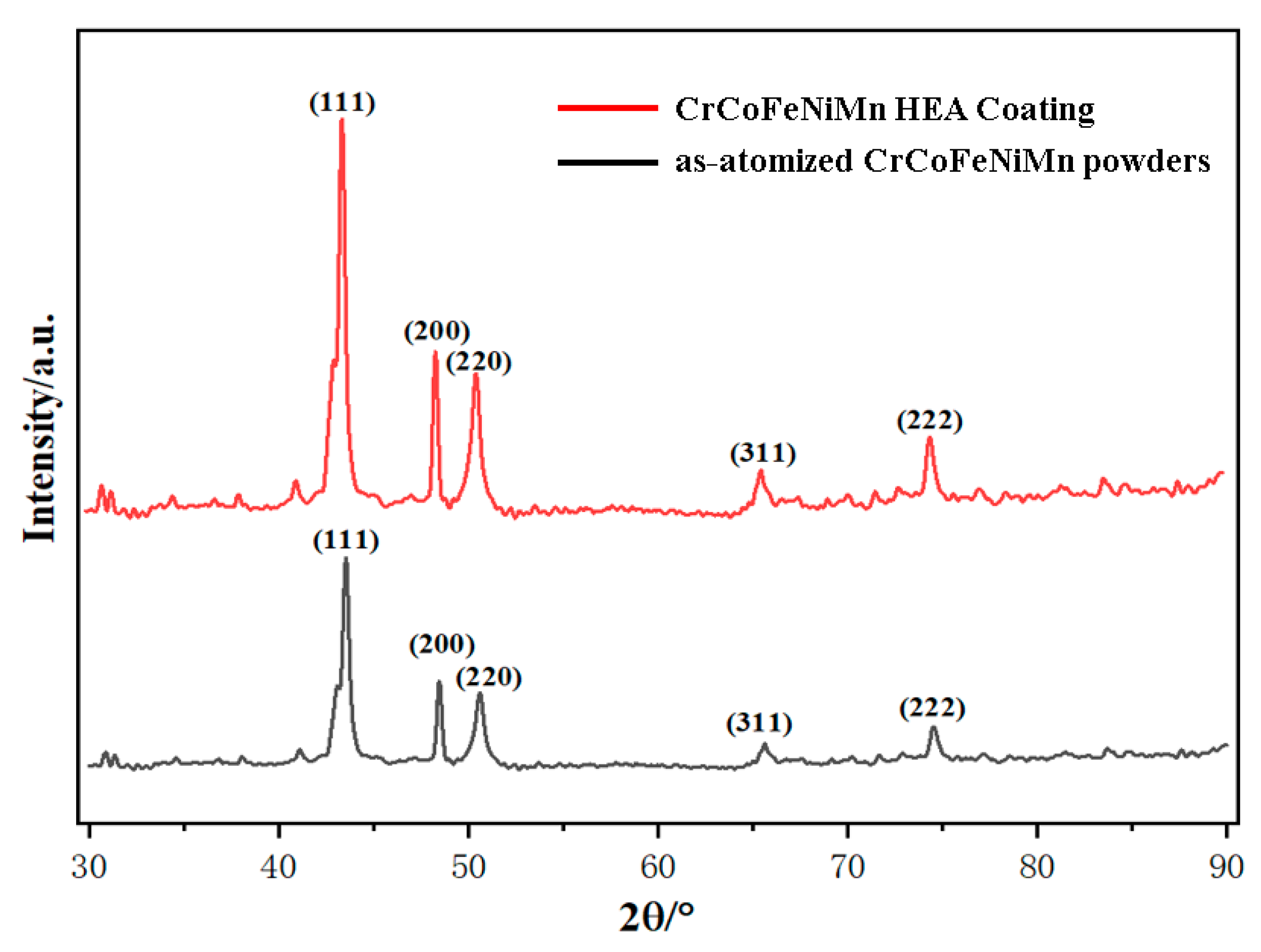
SEM micrographs of the substrate and some areas of the coating are shown in Figure 3a, showing the substrate structure; the substrate grains are large and irregularly arranged, with holes and cracks at grain boundary crossings. The irregular structure causes the alloy to have a large internal stress, which increases the likelihood of poor wear resistance, low hardness, cracking, and other defects. Figure 3b shows the crystal structure of the heat-affected zone (HAZ). It can be seen that the structure of the substrate undergoes a significant transformation near the HAZ, which is caused by the instantaneous change in the temperature gradient during the laser machining process. Figure 3b also shows a gradual change in grain structure from left to right, depending on the temperature region. The microstructure of the coating is shown in Figure 3c,d, where Figure 3c shows a typical equiaxial crystalline structure and Figure 3d shows a regular columnar crystalline structure. Detao Liu and his team demonstrated that the transformation of the microstructure in the coating region is closely related to changes in the internal temperature gradient (G) and solidification rate (R) [32]. In the lower part of the coating, the G/R ratio is higher, resulting in a microstructure primarily composed of columnar grains that grow in the direction of heat transfer. In the upper region of the coating, due to direct contact with air, the solidification rate (R) is higher, leading to the formation of numerous nuclei, which causes the columnar grain structure to transition to an equiaxed grain structure. Compared to the microstructure of the substrate in Figure 3a, it is clear that the microstructure of the coating is more regular and denser, and the size of the grains has been significantly refined, and orderly arrangement between the crystals is expected to result in a significant increase in the hardness and other properties of the alloy.

3.3. XRD Analysis

The XRD patterns of the CrCoFeNiMn HEA powder and CrCoFeNiMn HEA coating prepared by gas atomization are depicted in Figure 4. Both the coating and the powder display a single FCC phase structure, attributed to the high elemental stability of the CrCoFeNiMn HEA. Additionally, it is observed that the intensity of the diffraction peaks in the coating region is significantly greater than that of the powder. The image analysis identifies the crystal plane corresponding to the strongest diffraction peak as (111). Liu et al. showed that (111) surface grains are characterized by a tight and dense arrangement, strong anisotropy, and higher binding energy [33]. Numerous researchers have reported that after laser processing, the strongest diffraction peaks in each melted coating shifted to the left, which is also observed in this experiment. The (111) peak is shifted to the left from 43.535° to 43.327°. Zhu and his coworkers examined the variation of the offset angle using Bragg’s law and explained the shift of the diffraction peak [34]. According to Equations (1) and (2) [35], the lattice parameters of the CrCoFeNiMn HEA powder and CrCoFeNiMn HEA coating prepared by gas atomization are 3.602 Å and 3.611 Å, respectively. A study by Mohsen and his team found that an increase in lattice parameter and lattice strain led to a shift in the position of the (111) peak in a CrCoFeNiMn HEA to a lower Bragg angle while improving the mechanical properties of the HEA [36].
n λ = 2 d sin ( θ )
n is the order of diffraction, λ is the wavelength of the incident X-ray, d is the interplanar spacing, and θ is the angle of incidence.
d = a h 2 + k 2 + l 2
a is the lattice constant, and h, k, and l represent the Miller indices of the crystallographic planes.

3.4. Microstructure Characterization

The EBSD IPF maps of the substrate and CrCoFeNiMn HEA coating regions are presented in Figure 5. Microstructure changes in the substrate region along the laser processing direction are depicted in Figure 5a,b. The figure reveals coarse and irregularly arranged grains in the substrate region. As the laser moves, the heat-affected zone (HAZ) structure gradually appears in the coating area, as shown in Figure 5c, resembling the microstructure observed in Figure 3b. Additionally, Figure 5d illustrates the grain structure of the coating area, showcasing a fine and densely aligned uniform equiaxial crystal structure.
Figure 6 shows the Misorientation angle and grain size distribution of the substrate and coating regions. Figure 7 shows the evolution process of the grain structure. Initially, subgrain boundaries were formed inside the grains due to laser strengthening during laser processing of the substrate, as shown in Figure 7a. Furthermore, according to the experimental data shown in Figure 6a,b, the fLAGBS increased from 58.7% to 85.7% before and after laser processing, while the number of low-angle grain boundaries (i.e., those with an orientation angle between 2° and 5°) gradually increased after laser processing, demonstrating that the grain structure of the original substrate was transformed into multiple subgranular structures under the laser enhancement. Figure 6c,d shows the particle size distribution of the substrate and coating; the data in the figure indicate that the average particle size decreased from 64.19 μm to 16.59 μm. The occurrence of this phenomenon in the HEA is dependent on the cooling rate. Li Bo’s study also showed that an increase in the cooling rate leads to a finer grain structure, thus demonstrating that the microstructure is optimized after laser processing [37]. Under the conditions of grain refinement and an increasing proportion of small-angle grain boundaries, the transformation of grain structure is shown in Figure 7a–e. The transformation mechanism of the grain structure within the substrate and coating is illustrated in Figure 7. Figure 7a,b depict the microstructure of the substrate region, characterized by predominant large-angle grain boundaries. Following laser intensification, the number of small-angle grain boundaries in the substrate region increases, gradually transforming the grains into a columnar crystal structure in the coating, facilitated by the subgrain boundary structure shown in Figure 7b1. As the cooling rate increases along with the number of small-angle grain boundaries, subgrain boundary structures emerge at the grain boundaries of the columnar crystals, as depicted in Figure 7c1. Simultaneously, grain refinement continues in the coating, eventually transforming into the equiaxed crystal structure shown in Figure 7d. Chong Z’s research also indicated that dislocations, as one of the main defects of a HEA, have a significant influence on its hardness and plasticity and that the ratio of LAGB to the number of dislocations has a positive correlation [38]. According to the experimental data, the LAGB ratio of the coating is significantly increased, indicating that more dislocations have been generated in the region. The increase in the ratio of dislocations will pin and entangle the dislocations with each other, effectively preventing the dislocation slippage and ultimately improving the strength of the material.
The TEM observations are depicted in Figure 8. Obvious dislocation line structures are observed at the edge of the coating, as shown in Figure 8a. The lattice structure of the localized region is analyzed using the Laplace transform with the inverse Laplace transform, and the results are presented in Figure 8(a1). The generation of dislocation structures is associated with the characteristics of the laser cladding process, wherein rapid heating and cooling of the material, along with plastic deformation, can induce the formation of dislocation structures. Twinning structures, as well as dislocation wall structures, were also observed in the center region of the coating, as shown in Figure 8b. The interface of the twinning serves as the primary source of dislocations. While the twinning absorbs a significant number of dislocation structures, it can also effectively restrict the slip of dislocations, thereby reducing the stresses within the material and enhancing its strength. Combined with the above analysis, the CrCoFeNiMn HEA coatings prepared by gas atomization and laser cladding exhibit a mechanism of fine grain strengthening, along with synergistic strengthening from dislocation and twinning.

3.5. Microhardness and Mechanical Properties

The microhardness test results are shown in Figure 9. In the substrate region (0–600 µm), the microhardness ranges from 174.76 to 231.89 Hv0.1, with an average microhardness of 195.56 Hv0.1. In the HAZ region (600–900 µm), the microhardness ranges from 207.43 to 289.11 Hv0.1, with an average microhardness of 241.35 Hv0.1. The HAZ is a transition area between the coating and the substrate. Although this region does not completely melt when the substrate is heated, its microstructure changes, as shown in the SEM results in Figure 3. Consequently, the microhardness of the HAZ is higher compared to the substrate. In the coating region (900–1500 µm), the microhardness ranges from 278.54 to 365.08 Hv0.1, with an average recorded microhardness of 324.74 Hv0.1. This can be attributed to the grain refinement shown in Figure 6. Du and colleagues found that the microhardness of a CrCoFeNiMn HEA prepared by hot pressing and the sintering process was in the 205–251 HV range [39]. The results show that the microhardness of the HEA coatings prepared by laser cladding is significantly increased.
On the basis of microhardness experiments, this study conducted a micrometer scratch experiment. Figure 10a,b depicts the 3D morphology and depth analysis of the scratches using the Vk analyzer. According to the data in Figure 10b, the depth of the scratches at the substrate was in the range of 15–30 μm and the depth of the scratches in the coating was in the range of 5–10 μm, which indicates that the depth of the scratches decreased gradually along the laser processing direction from the substrate to the coating. SEM micrographs of micrometer scratches are shown in Figure 10c,d. The topography of the scratches on the substrate shown in Figure 10c. reveals that obvious cracks and spalling appeared during the scratching process, which may be attributed to the poor plasticity of the substrate. Furthermore, in the SEM image of the scratch tail area and the magnified image of the defect in Figure 10d, the cracking and spalling are more clearly observed, which are caused by the excessive internal stress of the substrate cracking after being loaded. Through the above experiments, we can verify the results observed and analyzed in the EBSD. The micromechanical properties of the CrCoFeNiMn HEA coatings were significantly improved due to the synergistic effect of fine grain strengthening and twinning dislocation strengthening.

3.6. Friction and Wear Properties

The friction test machine measures the frictional force and normal pressure in the coating and substrate regions during the wear process using pressure and displacement sensors. Instantaneous friction coefficients μi at each time point are calculated using Equation (3), as shown in Figure 11. The selection of 10N was made to investigate the frictional characteristics of the coating at a microscale, expanding the experimental applicability while reducing the influence of thermal effects on the experimental outcomes for improved accuracy. The friction coefficient curves for both the coating and the substrate showed two stages. In Figure 11, the period from 0 to 800 s represents the running-in stage of the wear process, where the friction coefficient increases sharply within a short time and then fluctuates. This is due to the initially small friction contact area, causing fractures and fragmentation on the friction surfaces. As the friction time increases, the wear process enters a steady-state stage (800–1800 s), during which the fluctuation range of the friction coefficient decreases and stabilizes. According to the instantaneous friction coefficient µi in the steady-state stage shown in Figure 11, the average friction coefficient µ for the coating and substrate regions is calculated using Formula (4). The average friction coefficient for the substrate was 0.6672, while for the coating, it was 0.6024. The friction coefficient of the coating decreased by approximately 9.71%, indicating a significant improvement in wear resistance compared to the substrate.
μ i = F f i F n
where Ffi is the friction force at the i-th measurement point, and Fn is the normal pressure.
μ = i = 1 n μ i n
where n is the number of measurement points in the steady state stage.
The SEM morphology of the coating wear region is shown in Figure 12. Figure 12a shows the localized morphology of the wear zone. A large number of grooves can be observed along the direction of friction, while the formation of some spalls is found to be characteristic of abrasive wear. A higher number of microcracks in Figure 12b is due to the high-stress concentration during the wear process. At the same time, rubbing on the microcracked surface causes micron-sized debris to flake off on both sides of the crack. During friction, the alloy debris flakes off from the interior of the coating and binds to the surface area of the coating, eventually forming the mechanically mixed layer shown in Figure 12b. Wu’s study showed that mechanically mixed layers can effectively hinder plastic deformation and improve the wear resistance of the coating [40]. In Figure 12c, the surface of the abrasion marks is smooth, there is no accumulation of abrasive debris in the groove area, and a clear abrasive grain pit can be observed at the bottom of the image. In addition, adhesive buildup of alloy particles is seen in Figure 12d, which is caused by frictional heat as well as pressure during wear.
H. Tekdir et al. found that plasma diffusion treatment of Ti6 Al 4V/316L layered composites resulted in the formation of hard and thick modified layers [41]. During friction experiments, adhesive contact was observed on the alloy surface, resulting in a decrease in scratch depth and an improvement in the hardness and wear resistance of the HEA. As one of the primary indicators of a material’s resistance to wear, it is crucial to acknowledge that wear resistance cannot be enhanced without the impact of hardness.
EDS analysis was conducted on the abrasive grains of region 1, as depicted in Figure 12d, with the results presented in Figure 12e. In the figure, the alloy surface exhibits a notable presence of O elements, attributed to the development of an oxide layer on the alloy surface due to friction and subsequent separation by adhesive wear. Additionally, the elevated Fe element content could result from the detachment of wear chips from the surface during the wear process. This observation suggests that the primary wear mechanism of the coating involves a combination of adhesive and abrasive wear, leading to the formation of a coating with commendable wear resistance.
The 3D morphology of the wear region is shown Figure 13, where Figure 13a,b show the wear morphology of the localized regions of the substrate and coating, respectively. It can be found that the substrate and coating have different wear values on the wear trajectory, and the depth of wear of the coating is significantly reduced compared to the substrate. At the same time, a large amount of dark blue debris flaking can be observed in the substrate wear region, while the coating region is relatively smooth and has a low roughness. These phenomena are due to the good bonding properties of the laser cladding process and the high wear resistance of the coating. Figure 13a1,b1 show the depth profiles of the substrate and coating wear areas, respectively. The data in the figure show that the maximum wear depth in the substrate region is 151.69 μm and in the coating region it is 52.19 μm. The coating wear depth is reduced by 65.59% as compared to the substrate. The microhardness in the coating area is increased by 66.06% relative to the substrate. In summary, the CrCoFeNiMn HEA coating prepared using laser cladding technology exhibits significantly improved hardness and wear resistance compared to the 316L stainless steel substrate.

4. Conclusions

In this study, a spherical CrCoFeNiMn HEA powder with uniform particle size was first prepared using the gas atomization method. Subsequently, high-quality CrCoFeNiMn HEA coatings were prepared on the surface of a 316L stainless steel substrate using a prepositioned powder-type laser cladding method. The reinforcing mechanism of the HEA coatings was investigated through microstructure observation. Additionally, the mechanical and wear characteristics of the coatings were tested and analyzed. The conclusions drawn from this study are as follows:
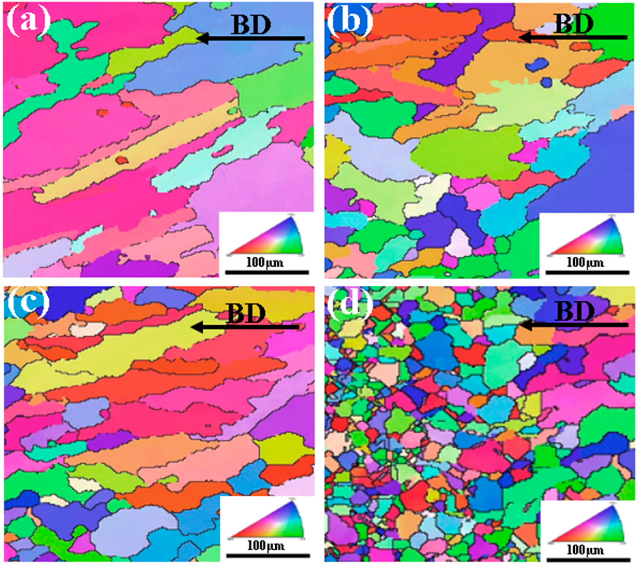
  • The CrCoFeNiMn HEA coating prepared by laser cladding shows significant microstructural optimization compared to the 316L stainless steel substrate. The coarse and uneven grain structure of the substrate is transformed into a dense and uniform columnar equiaxed structure.
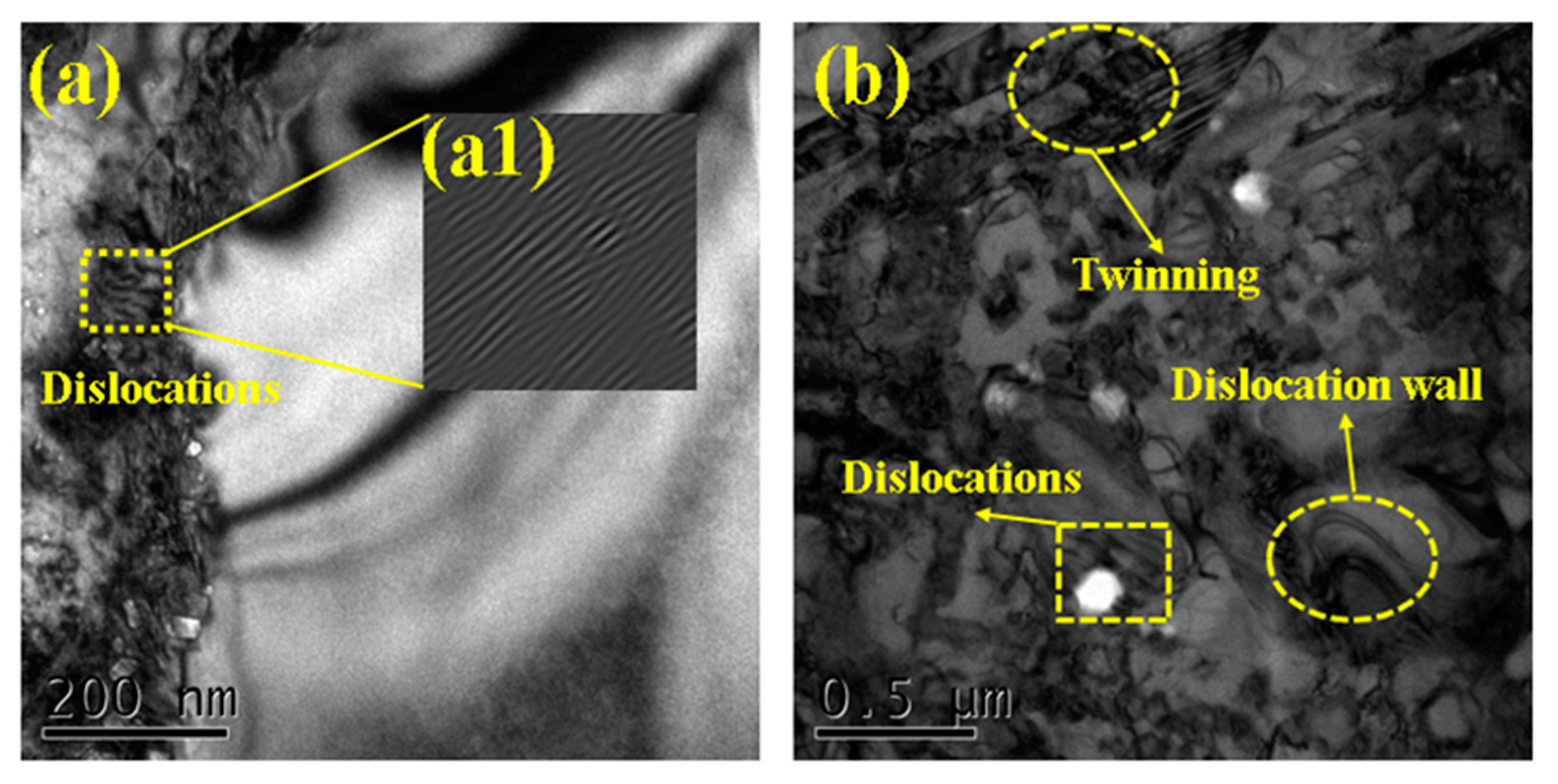
  • Under the influence of the subgrain boundary structure, the internal grain structure of the coating is refined by 74.15% when compared to the substrate. Simultaneously, a synergistic strengthening phenomenon involving twinning and dislocations was observed in the coating area. This indicates that the strengthening mechanisms of laser cladding technology include grain refinement and the synergistic effects of twinning and dislocations.
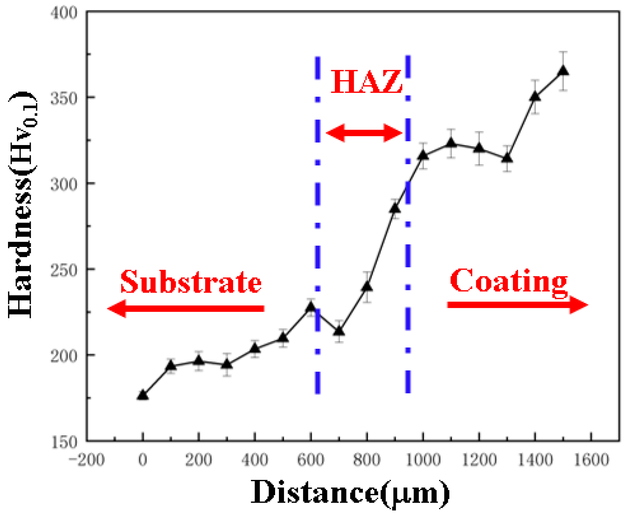
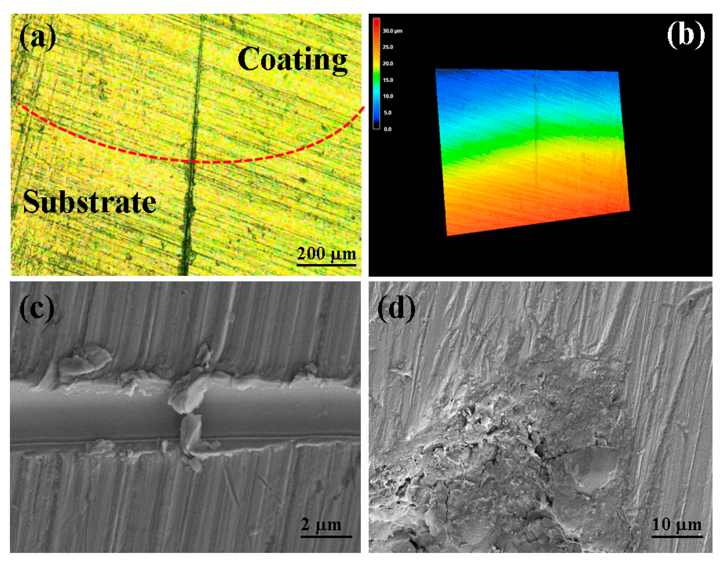
  • Due to the observed grain refinement in the EBSD and TEM experiments, along with the synergistic strengthening effects of twinning and dislocations, the microhardness of the coating increased by approximately 66.06% when compared to the substrate. Additionally, during microscratch tests, there were fewer cases of surface delamination and cracking in the coating.
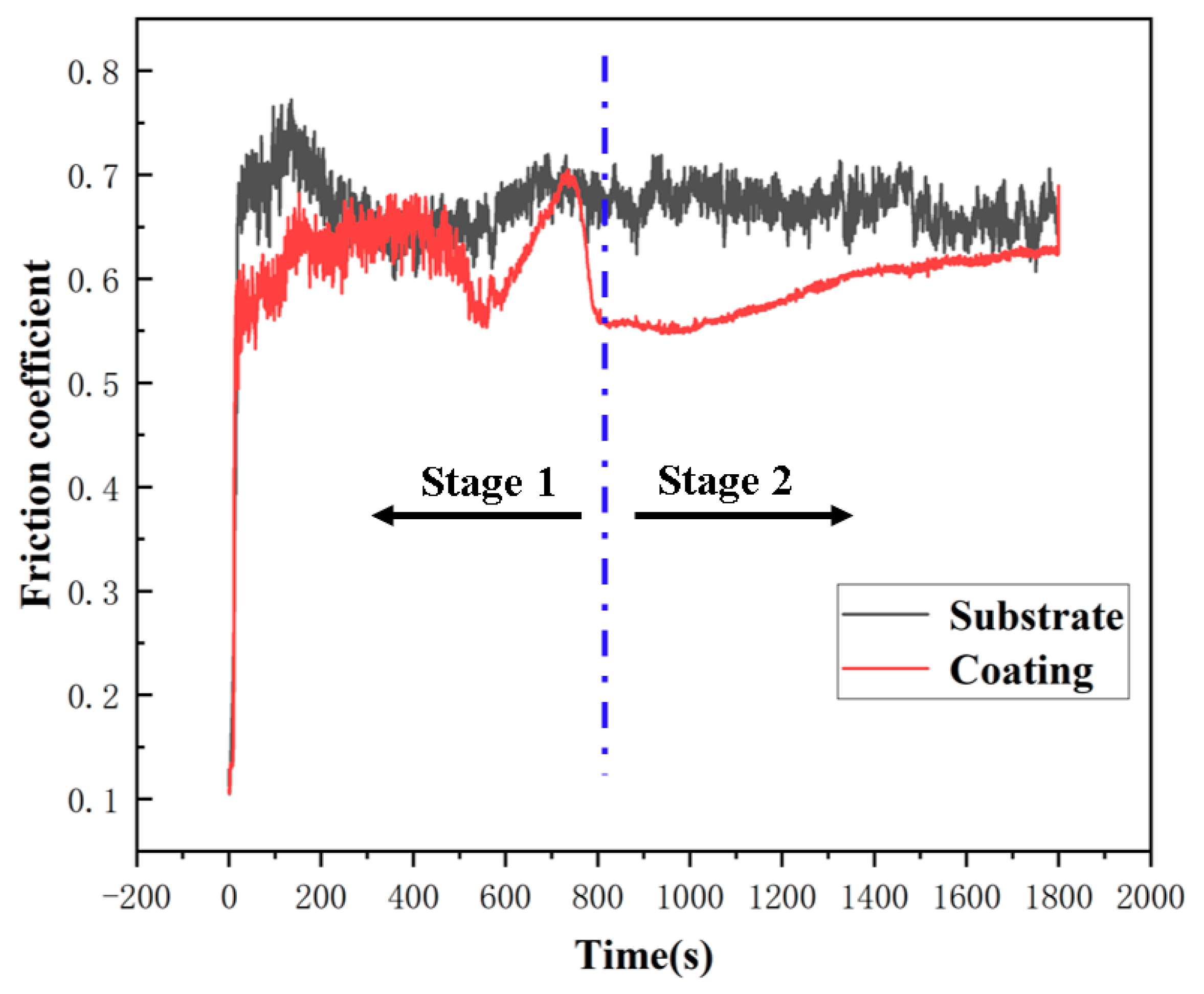
  • The coating region exhibits a combination of abrasive and adhesive wear characteristics. Furthermore, the mechanical alloying structure enhances the wear resistance of the coating area. When compared to the substrate, the maximum wear depth in the coating region decreased by 65.69%.

Author Contributions

Writing—review and editing, H.T.; data curation, H.T. and X.W.; review and editing, Y.Y.; resources, F.C. and H.L. All authors have read and agreed to the published version of the manuscript.

Funding

This work was supported by The National Natural Science Foundation of China for financial support (No. 52205318), the Postgraduate Research & Practice Innovation Program of Jiangsu Province (SJCX23_XY040).

Institutional Review Board Statement

Not applicable.

Informed Consent Statement

Informed consent was obtained from all subjects involved in the study.

Data Availability Statement

Data are contained within this article.

Conflicts of Interest

We declare that we have no financial and personal relationships with other people or organizations that can inappropriately influence our work; there is no professional or other personal interest of any nature or kind in any product, service and company that could be construed as influencing the position presented in, or the review of, the manuscript entitled.

References

  1. Farias, M.; Hu, H.; Zhang, S.; Li, J.; Xu, B. A Molecular Dynamics Study of Atomic Diffusion Effects on Thermomechanical Properties Applying Laser Additive Alloying Process for the Cantor High Entropy Alloy. J. Manuf. Process. 2023, 91, 149–166. [Google Scholar] [CrossRef]
  2. Olumor, I.D.; Wiśniewska, M.; Torresani, E.; Olevsky, E.A. Additive Manufacturing and Spark Plasma Sintering as Effective Routes for Manufacturing of AISI 316L Austenitic Stainless Steel-WC Composites. J. Mater. Res. Technol. 2023, 26, 3234–3244. [Google Scholar] [CrossRef]
  3. Kong, J.; Luo, G.; Tian, Y.; Du, C. Atomic Insight into Tribological Behavior of AlCoCrFeNi High Entropy Alloy at Various Nanoscratching Conditions. J. Mater. Res. Technol. 2023, 27, 7293–7303. [Google Scholar] [CrossRef]
  4. Zhu, B.; Zhao, D.; Niu, Y.; Zhang, Z.; Zhao, H. Atomic Study on the Deformation Behavior of Nanotwinned CoCrCuFeNi High Entropy Alloy during Nanoscratching. J. Mater. Res. Technol. 2023, 25, 4020–4035. [Google Scholar] [CrossRef]
  5. Zhang, C.; Song, H.; Oliveros, D.; Fraczkiewicz, A.; Legros, M.; Sandfeld, S. Data-Mining of in-Situ TEM Experiments: On the Dynamics of Dislocations in CoCrFeMnNi Alloys. Acta Mater. 2022, 241, 118394. [Google Scholar] [CrossRef]
  6. Luo, H.; Long, B.; Lu, S.; Guo, L.; Luo, F.; Lin, W.; Cao, J.; Yin, Z.; Zhao, P. Dislocation Loops, Segregation and Hardening Induced by High-Dose Ion Irradiation of NbMoTaW and VCrTaW High-Entropy Alloy Coatings on the T91 Substrate. Surf. Coat. Technol. 2023, 473, 130019. [Google Scholar] [CrossRef]
  7. Gaddam, S.; Behera, A.K.; Arai, N.; Zhang, Q.; Mishra, R.S. Effect of Milling Time and Sintering Temperature on the Microstructure and Binder Distribution of Spark Plasma Sintered NbC-Ni Cermets. Int. J. Refract. Met. Hard Mater. 2023, 115, 106323. [Google Scholar] [CrossRef]
  8. Wang, Z.; Liu, P.; Wang, A.; Xie, J.; Hou, B. Effect of Spark Plasma Sintering Temperature on the Multi-Scale Microstructure Evolution and Mechanical Properties of Ti2AlC/TiAl Composites with Network Architecture. J. Mater. Res. Technol. 2023, 25, 6209–6223. [Google Scholar] [CrossRef]
  9. Zhao, T.; Wang, L.; Zhang, S.; Zhang, C.H.; Sun, X.Y.; Chen, H.T.; Bai, X.L.; Wu, C.L. Effect of Synergistic Cavitation Erosion-Corrosion on Cavitation Damage of CoCrFeNiMn High Entropy Alloy Layer by Laser Cladding. Surf. Coat. Technol. 2023, 472, 129940. [Google Scholar] [CrossRef]
  10. Ling, J.; Li, J.; Zhou, J.; Lin, M.; Huang, J.; Gao, P.; Xue, B. Evolution of the Interfacial Microstructure in 316L/AlxCoCrFeNi Composite Material Induced by High-Velocity Impact Welding. Mater. Charact. 2024, 211, 113929. [Google Scholar] [CrossRef]
  11. Ren, X.; Sun, W.; Tian, S.; Zhu, C.; Qin, M.; Yang, Y.; Wu, W. Tribological and Electrochemical Behaviors of FeCoNiCrMox HEA Coatings Prepared by Internal Laser Cladding on 316L Steel Tube. Mater. Charact. 2024, 211, 113906. [Google Scholar] [CrossRef]
  12. Li, J.; Wang, C.; Zhu, S.; Wang, T.; Chai, L.; Li, Q.; Luo, J. Effects of Laser Power on Microstructures and Mechanical Properties of CoCrFeNiMn High Entropy Alloy with the Addition of Y2O3 by Directed Energy Deposition. Opt. Laser Technol. 2024, 169, 110122. [Google Scholar] [CrossRef]
  13. Liu, Y.; Ren, J.; Liu, J.; Cao, Y.; Liu, W.; Li, T.; Zhu, Y.; Chen, W. Exceptional Thermal Stability of Additively Manufactured CoCrFeMnNi High-Entropy Alloy with Cellular Dislocation Structures. Mater. Sci. Eng. A 2023, 885, 145650. [Google Scholar] [CrossRef]
  14. Akinwande, A.A.; Balogun, O.A.; Adediran, A.A.; Adesina, O.S.; Romanovski, V.; Jen, T.C. Experimental Analysis, Statistical Modeling, and Parametric Optimization of Quinary-(CoCrFeMnNi)100 –x/TiCx High-Entropy-Alloy (HEA) Manufactured by Laser Additive Manufacturing. Results Eng. 2023, 17, 100802. [Google Scholar] [CrossRef]
  15. Cui, Y.; Shen, J.; Geng, K.; Hu, S. Fabrication of FeCoCrNiMnAl0.5-FeCoCrNiMnAl Gradient HEA Coating by Laser Cladding Technique. Surf. Coat. Technol. 2021, 412, 127077. [Google Scholar] [CrossRef]
  16. Şimşek, T.; Kavaz, E.; Güler, Ö.; Şimşek, T.; Avar, B.; Aslan, N.; Almisned, G.; Zakaly, H.M.H.; Tekin, H.O. FeCoNiMnCr High-Entropy Alloys (HEAs): Synthesis, Structural, Magnetic and Nuclear Radiation Absorption Properties. Ceram. Int. 2023, 49, 25364–25370. [Google Scholar] [CrossRef]
  17. Kim, E.S.; Ramkumar, K.R.; Karthik, G.M.; Jeong, S.G.; Ahn, S.Y.; Sathiyamoorthi, P.; Park, H.; Heo, Y.-U.; Kim, H.S. Cryogenic Tensile Behavior of Laser Additive Manufactured CoCrFeMnNi High Entropy Alloys. J. Alloys Compd. 2023, 942, 169062. [Google Scholar] [CrossRef]
  18. He, R.; Wu, M.; Jie, D.; Cui, C.; Ou, B.; Miao, X.; Gong, Y. A Novel Approach to Regulate the Microstructure of Laser-Clad FeCrNiMnAl High Entropy Alloy via CeO2 Nanoparticles. Surf. Coat. Technol. 2023, 473, 130026. [Google Scholar] [CrossRef]
  19. Liu, X.; Zhu, Y.; Wang, C.; Han, K.; Zhao, L.; Liang, S.; Huang, M.; Li, Z. A Statistics-Based Study and Machine-Learning of Stacking Fault Energies in HEAs. J. Alloys Compd. 2023, 966, 171547. [Google Scholar] [CrossRef]
  20. Zavdoveev, A.; Zrodowski, Ł.; Vedel, D.; Cortes, P.; Choma, T.; Ostrysz, M.; Stasiuk, O.; Baudin, T.; Klapatyuk, A.; Gaivoronskiy, A.; et al. Atomization of the Fe-Rich MnNiCoCr High-Entropy Alloy for Spherical Powder Production. Mater. Lett. 2024, 363, 136240. [Google Scholar] [CrossRef]
  21. Liu, L.; Zhang, J.; Zhang, Q.; Zhai, C.; Zheng, H. Computational Insights into Gas Atomization of FeCoNiCrMoBSi High-Entropy Alloy: From Droplet Formation to Rapid Solidification. Int. J. Heat Mass Transf. 2024, 228, 125628. [Google Scholar] [CrossRef]
  22. Mehta, A.; Huynh, T.; Kljestan, N.; Graydon, K.; Mahmud, A.; Knezevic, M.; McWilliams, B.; Cho, K.; Sohn, Y. Additive Manufacturing of Al18Co30Cr10Fe10Ni32 High Entropy Alloy by Gas Atomization and Laser Powder Bed Fusion. Mater. Lett. 2023, 350, 134942. [Google Scholar] [CrossRef]
  23. Yang, T.; Cai, B.; Shi, Y.; Wang, M.; Zhang, G. Preparation of Nanostructured CoCrFeMnNi High Entropy Alloy by Hot Pressing Sintering Gas Atomized Powders. Micron 2021, 147, 103082. [Google Scholar] [CrossRef] [PubMed]
  24. Chiu, S.-M.; Lin, T.-T.; Sammy, R.K.; Kipkirui, N.G.; Lin, Y.-Q.; Liang, J.-T.; Chen, S.-H. Investigation of Phase Constitution and Stability of Gas-Atomized Al0.5CoCrFeNi2 High-Entropy Alloy Powders. Mater. Chem. Phys. 2022, 275, 125194. [Google Scholar] [CrossRef]
  25. Pan, W.; Fu, P.; Li, Z.; Chen, H.; Tang, Q.; Dai, P.; Liu, C.; Lin, L. Microstructure and Mechanical Properties of AlCoCrFeNi2.1 Eutectic High-Entropy Alloy Synthesized by Spark Plasma Sintering of Gas-Atomized Powder. Intermetallics 2022, 144, 107523. [Google Scholar] [CrossRef]
  26. Yu, H.; Zhang, N.; Zhou, G.; Han, J.; Li, D.; Chen, L. Physical Models for Vacuum-Induced Multistage Atomization of High-Entropy FeCoCrNiMo Alloy Powder for 3D Printing. J. Mater. Res. Technol. 2023, 24, 5947–5955. [Google Scholar] [CrossRef]
  27. Ji, F.; Xu, H.; Wang, Z.; Liu, R.; Feng, S.; Liu, X.; Gu, L.; Liu, Z.; Bai, Y. Microstructural Refinement and Tensile Properties of Fe65.7Ni11.7Ti1Mo6.6Co15 HEA Undergoing Multiple LSP. J. Alloys Compd. 2023, 967, 171719. [Google Scholar] [CrossRef]
  28. Krishna, S.A.; Radhika, N.; Saleh, B.; Manivannan, S. Microstructural Mechanical and Corrosion Properties of SS304/HEA Surface Layer Produced by Friction Stir Processing. J. Alloys Compd. 2023, 953, 170153. [Google Scholar] [CrossRef]
  29. Luo, F.; Wang, S.; Shi, W.; Xiong, Z.; Huang, J. Analysis of the Wear Behavior and Corrosion Resistance of CoCrFeNiMn-2% CNTs Laser Cladding Composite Coating. J. Mater. Res. Technol. 2024, 30, 6910–6923. [Google Scholar] [CrossRef]
  30. Liu, H.; Wang, R.; Hao, J.; Liu, X.; Chen, P.; Yang, H.; Zhang, T. Microstructural Evolution and Wear Characteristics of Laser-Clad CoCrFeNiMn High-Entropy Alloy Coatings Incorporating Tungsten Carbide. J. Alloys Compd. 2024, 976, 173124. [Google Scholar] [CrossRef]
  31. Zheng, K.; Tang, J.; Jia, W.; Wang, Y.; Wang, J.; Shi, Y.; Zhang, G. Microstructure and Mechanical Properties of Al0.5CoCrFeNi HEA Prepared via Gas Atomization and Followed by Hot-Pressing Sintering. J. Mater. Res. Technol. 2024, 30, 5323–5333. [Google Scholar] [CrossRef]
  32. Liu, D.; Kong, D. Effects of WC–10Co4Cr and TiC Additions on Microstructure and Tribological Properties of Laser Cladded FeMnCoCr HEA Coatings. Ceram. Int. 2024, 50, 12108–12120. [Google Scholar] [CrossRef]
  33. Liu, S.; Li, Y.; Liu, F.; Zhang, H.; Ding, H. Effects of Relative Positioning of Energy Sources on Weld Integrity for Hybrid Laser Arc Welding. Opt. Lasers Eng. 2016, 81, 87–96. [Google Scholar] [CrossRef]
  34. Zhu, Z.G.; Nguyen, Q.B.; Ng, F.L.; An, X.H.; Liao, X.Z.; Liaw, P.K.; Nai, S.M.L.; Wei, J. Hierarchical Microstructure and Strengthening Mechanisms of a CoCrFeNiMn High Entropy Alloy Additively Manufactured by Selective Laser Melting. Scr. Mater. 2018, 154, 20–24. [Google Scholar] [CrossRef]
  35. Saboktakin Rizi, M.; Minouei, H.; Lee, B.J.; Toroghinejad, M.R.; Hong, S.I. Effects of Carbon and Molybdenum on the Nanostructural Evolution and Strength/Ductility Trade-off in Fe40Mn40Co10Cr10 High-Entropy Alloys. J. Alloys Compd. 2022, 911, 165108. [Google Scholar] [CrossRef]
  36. Jing, Q.; Hu, L.; Li, J.; Xia, S.; Huang, S.; Liu, L. Significant Strength Enhancement of High-Entropy Alloy via Phase Engineering and Lattice Distortion. J. Alloys Compd. 2024, 976, 172963. [Google Scholar] [CrossRef]
  37. Li, B.; Zhang, L.; Yang, B. Grain Refinement and Localized Amorphization of Additively Manufactured High-Entropy Alloy Matrix Composites Reinforced by Nano Ceramic Particles via Selective-Laser-Melting/Remelting. Compos. Commun. 2020, 19, 56–60. [Google Scholar] [CrossRef]
  38. Chong, Z.; Sun, Y.; Cheng, W.; Huang, L.; Han, C.; Ma, X.; Meng, A. Laser Remelting Induces Grain Refinement and Properties Enhancement in High-Speed Laser Cladding AlCoCrFeNi High-Entropy Alloy Coatings. Intermetallics 2022, 150, 107686. [Google Scholar] [CrossRef]
  39. Du, J.L.; Xu, X.; Zhang, H.M.; Lu, M.W.; Sun, J.F.; Luo, K.Y.; Lu, J.Z. Microstructure and Wear Resistance of CoCrFeNiMn Coatings Prepared by Extreme-High-Speed Laser Cladding. Surf. Coat. Technol. 2023, 470, 129821. [Google Scholar] [CrossRef]
  40. Wu, Y.; Du, C.; Yu, Z.; Wang, R.; Ren, X. Effect of Cu Content on the Microstructure and Mechanical Properties of Fe20Co30Ni10Cr20Mn20 FCC-Typed HEAs. Mater. Sci. Eng. A 2024, 897, 146336. [Google Scholar] [CrossRef]
  41. Tekdir, H.; Yetim, A.F. Additive Manufacturing of Multiple Layered Materials (Ti6Al4V/316L) and Improving Their Tribological Properties with Glow Discharge Surface Modification. Vacuum 2021, 184, 109893. [Google Scholar] [CrossRef]
Figure 1. Schematic diagram of the experimental process.
Coatings 14 00906 g001
Figure 2. (a) Displays the SEM image of atomized CrCoFeNiMn HEA powder, (b) represents the particle size distribution of atomized CrCoFeNiMn HEA powder, (c) shows the TEM image of the powder interior, and (d) presents the elemental composition analysis of the powder in the region.
Coatings 14 00906 g002
Figure 3. SEM electron micrographs of (a) CrCoFeNiMn HEA substrate, (b) HAZ, and (c,d) grain structure of the coating layer.
Coatings 14 00906 g003
Figure 4. XRD phase composition of coating.
Coatings 14 00906 g004
Figure 5. EBSD plots of the substrate and coating regions of CrCoFeNiMn HEA: (a,b) micro-structure of the substrate region, (c) Heat affected zone organization, and (d) HEA coating region organization.
Coatings 14 00906 g005
Figure 6. (a) Misorientation angle distribution in the substrate region, (b) misorientation angle distribution in the coating region, (c) grain size distribution in the substrate region, and (d) grain size distribution in the coating region.
Coatings 14 00906 g006
Figure 7. Explanation of the microstructure transformation mechanism in the laser cladding process, (a) substrate region, (b) substrate region, (b1) subgrain structure, (c) columnar grain structure, (c1) subgrain structure, and (d) equiaxed grain structure.
Coatings 14 00906 g007
Figure 8. TEM scan of the coating area: (a) microstructure of the coating edge, (a1) schematic diagram of dislocation structure, and (b) microstructure of the coating center.
Coatings 14 00906 g008
Figure 9. Microhardness of substrate and coating.
Coatings 14 00906 g009
Figure 10. (a) Scratch surface photomicrograph, (b) three-dimensional morphology of micrometer scale scratches, (c) SEM image of micrometer scratches, and (d) enlarged view of scratches in the substrate.
Coatings 14 00906 g010
Figure 11. Variation in coating and substrate coefficients of friction under 10N loading.
Coatings 14 00906 g011
Figure 12. SEM images of coating wear region: (a) localized morphology of coating wear region, (b) localized morphology of mechanically mixed layer, (c) morphology of wear edge region, (d) localized magnification of wear-off particles, and (e) region 1 chemical analysis.
Coatings 14 00906 g012
Figure 13. Three-dimensional morphology of wear areas: (a) localized area wear morphology of substrate, (a1) substrate wear depth and contour curve, (b) localized area wear morphology of coating, and (b1) coating wear depth and contour curve.
Coatings 14 00906 g013
Table 1. Chemical composition of gas-atomized CrCoFeNiMn powder (at%).
ElementCoCrFeNiMnO
Nominal composition20202020200
Actual composition19.74720.24319.49320.11720.3850.015
Table 2. Laser processing parameters.
ProcessParametersValues
Laser CladdingSpot size/mm3
Scanning speed/(mm/s)6
Power/W1300
Argon flow rate (min/L)5
Defocus (mm)5
Overlap rate (%)40
Disclaimer/Publisher’s Note: The statements, opinions and data contained in all publications are solely those of the individual author(s) and contributor(s) and not of MDPI and/or the editor(s). MDPI and/or the editor(s) disclaim responsibility for any injury to people or property resulting from any ideas, methods, instructions or products referred to in the content.

