
Microstructures and Corrosion Behaviors of Non-Equiatomic Al0.32CrFeTi0.73(Ni1.50−xMox)(x = 0, 0.23) High-Entropy Alloy Coatings Prepared by the High-Velocity Oxygen Fuel Method

Abstract
1. Introduction
2. Experimental Procedures
2.1. Coating Preparation
2.2. Electrochemical Measurements
3. Results and Discussion
3.1. Al0.32CrFeTi0.73Ni1.50 Coating
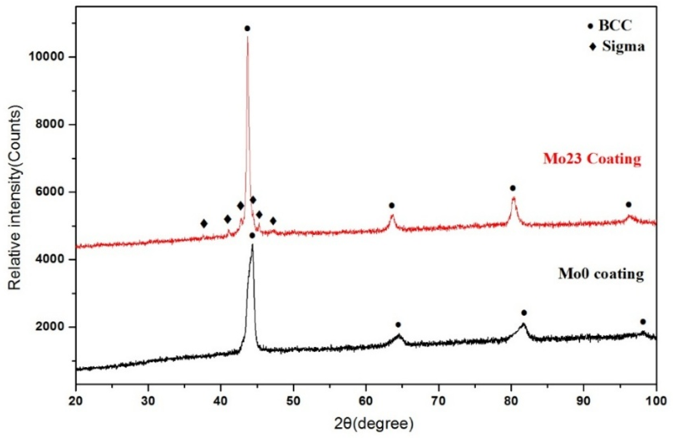
3.1.1. Structural Analysis
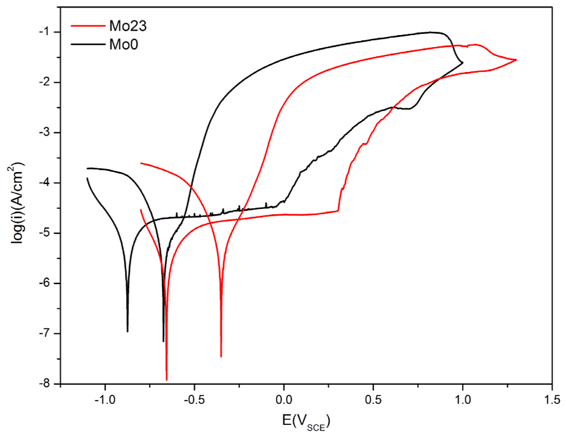
3.1.2. Potentiodynamic Polarization Tests
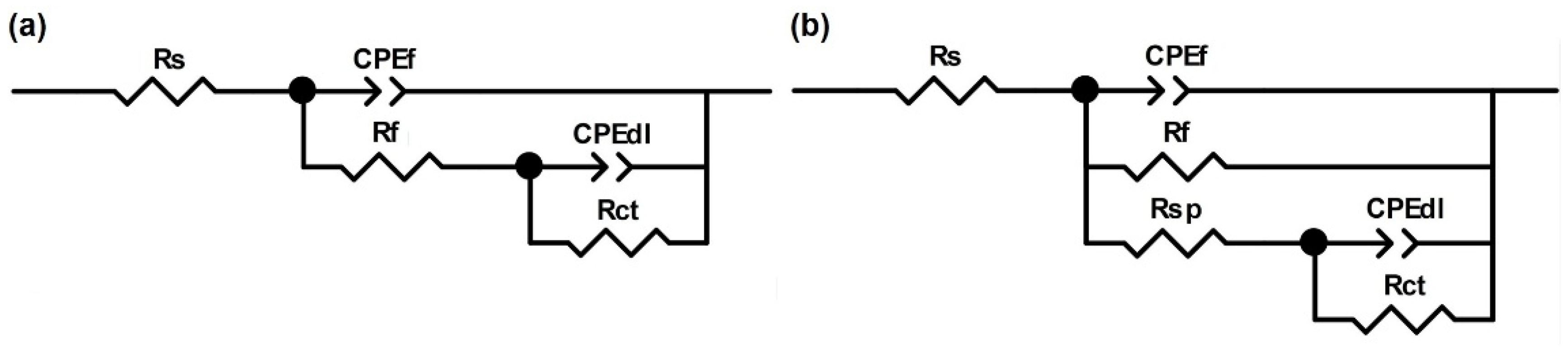
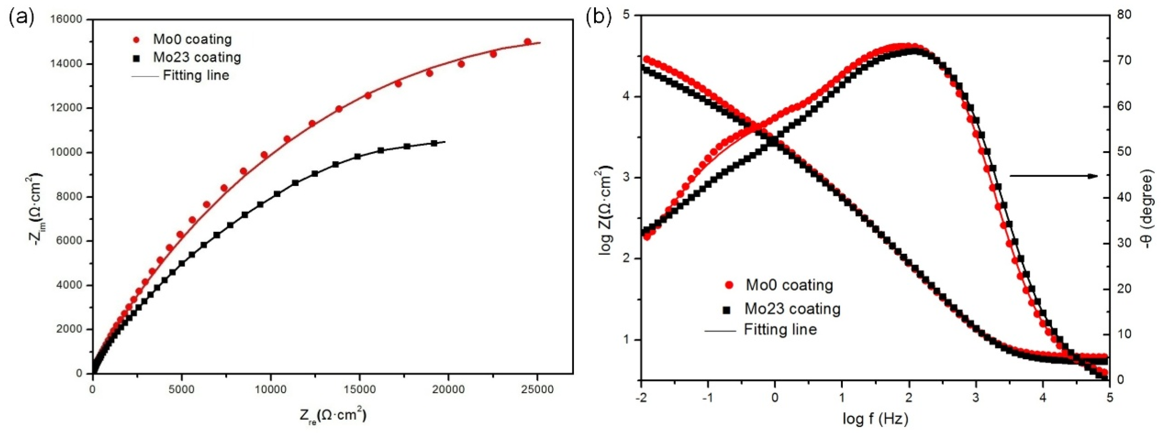
3.1.3. EIS Tests
3.1.4. Mott-Schottky Tests
3.2. Al0.32CrFeTi0.73Ni1.27Mo0.23 Coating
3.2.1. Structural Analysis
3.2.2. Potentiodynamic Polarization Tests
3.2.3. EIS Tests
3.2.4. Mott-Schottky Tests
4. Conclusions
- (1)
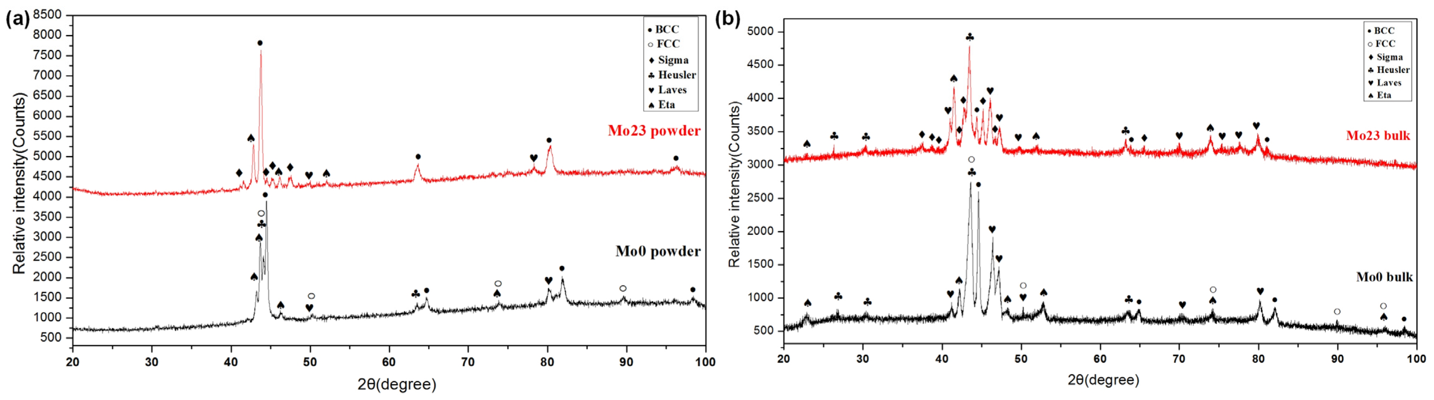
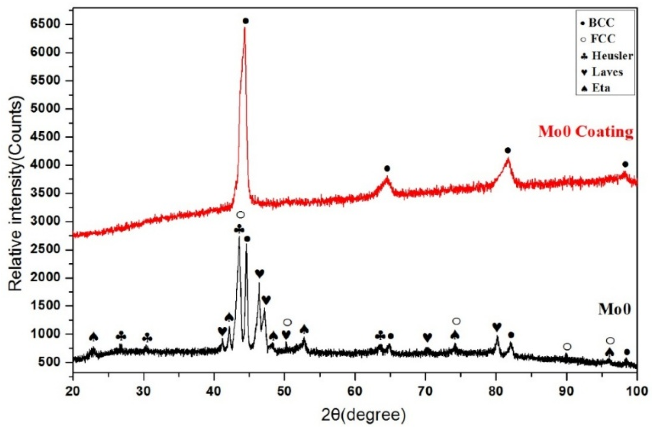
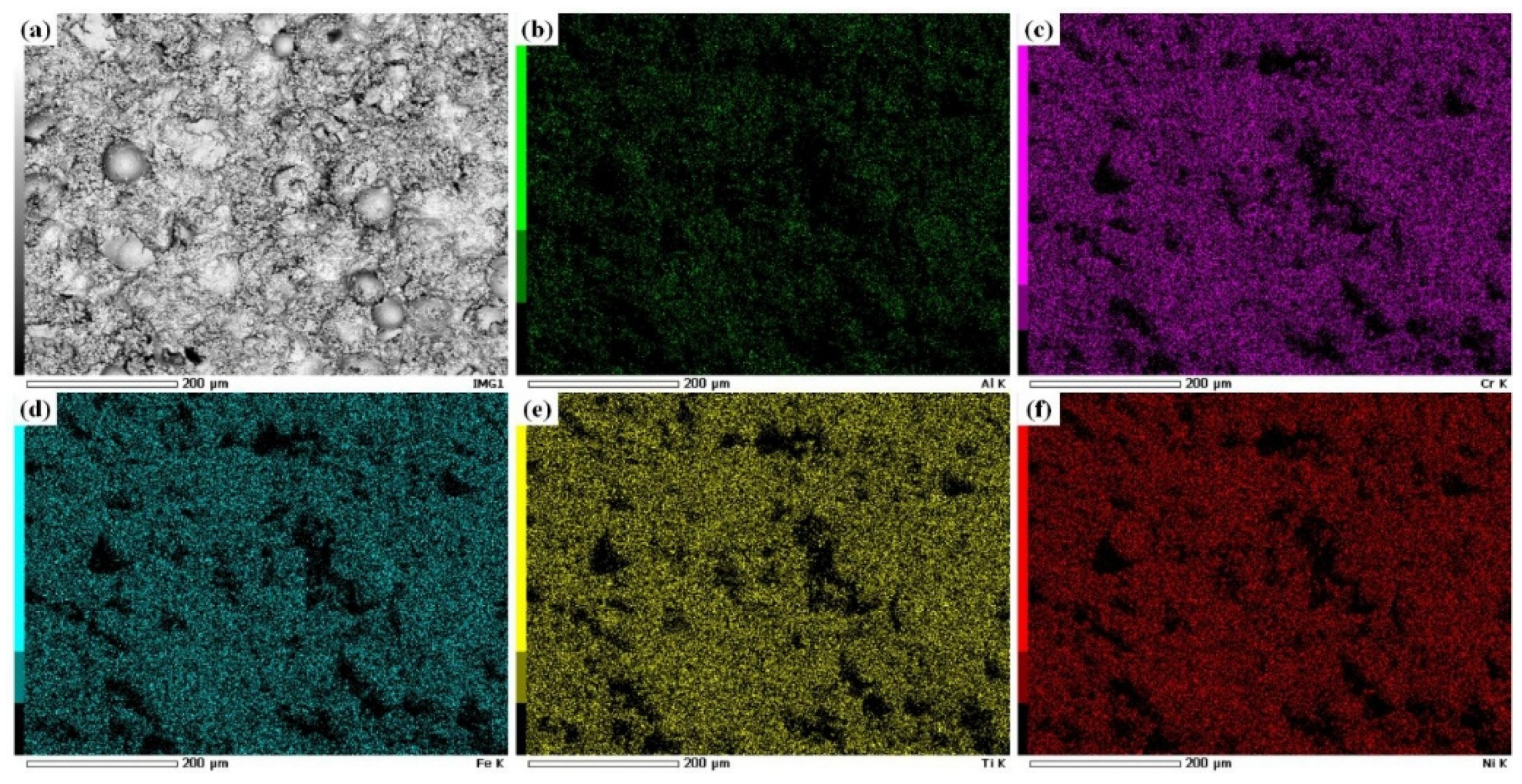
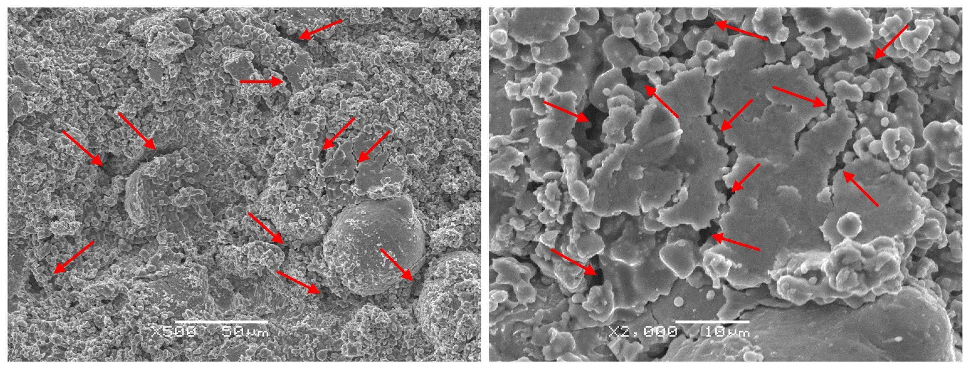
- The Al0.32CrFeTi0.73Ni1.50 coating is a simple BCC single-phase solid solution structure compared with the corresponding poly-phase composite bulk. The structure of the Al0.32CrFeTi0.73Ni1.27Mo0.23 coating, with the introduction of Mo element, is such that the (Cr, Mo)-rich Sigma phase precipitated out of the BCC solid solution matrix phase, thus forming Cr-depleted regions around the sigma phases. The solid solution of large atomic-size Mo element caused the lattice expansion of the BCC solid solution matrix phase. Micro-hole and micro-crack defects were formed on the surface of both coatings.
- (2)
- The growth of both passivation films of the Al0.32CrFeTi0.73Ni1.50 coating and the Al0.32CrFeTi0.73Ni1.27Mo0.23 coating was spontaneous. Both passivation films were stable and Cr2O3-rich P-type single-layer structures.
- (3)
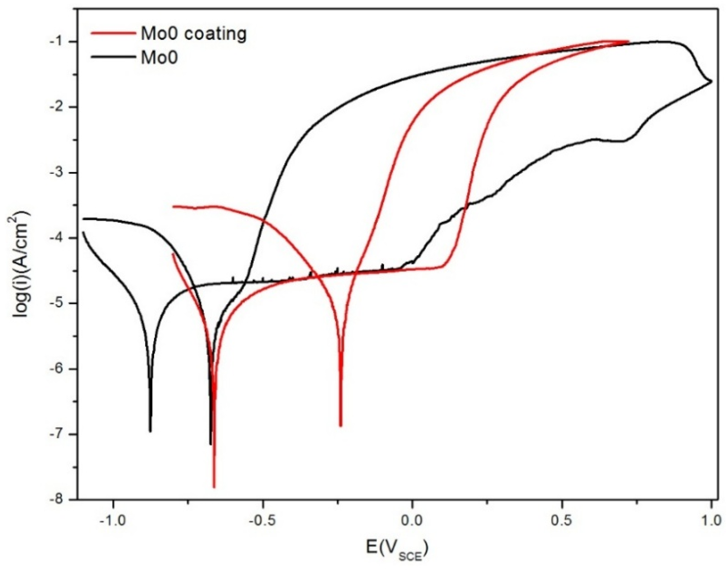
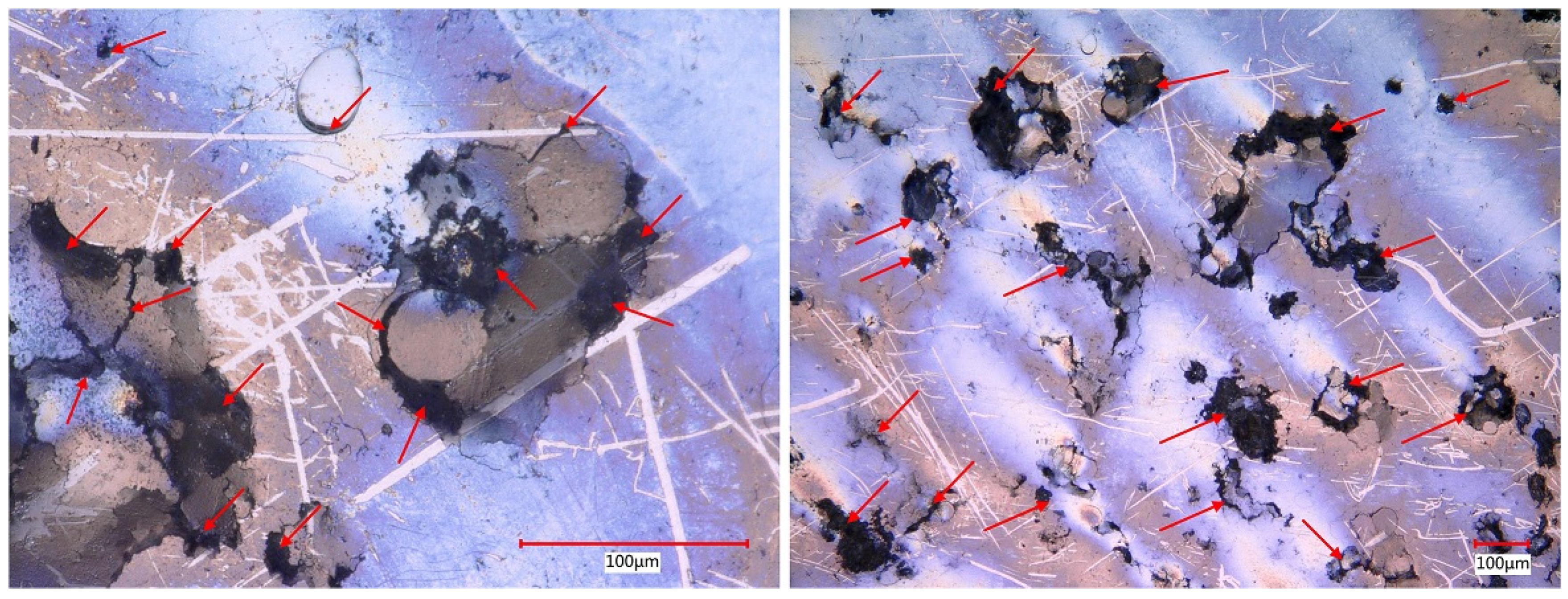
- The Al0.32CrFeTi0.73Ni1.50 coating had better corrosion resistance than the corresponding bulk. The pitting susceptibility of the coating was greatly reduced. The corrosion type of the coating was mainly pitting, occurring in the coating surface defects.
- (4)
- The Al0.32CrFeTi0.73Ni1.27Mo0.23 coating, with the introduction of Mo element, increased pitting susceptibility and deteriorated corrosion resistance compared with the Mo-free Al0.32CrFeTi0.73Ni1.50 coating. The corrosion type of the Mo-bearing coating was mainly pitting, occurring in the coating surface defects and Cr-depleted regions.
Author Contributions
Funding
Institutional Review Board Statement
Informed Consent Statement
Data Availability Statement
Acknowledgments
Conflicts of Interest
References
- Li, J.; Huang, Y.; Meng, X.; Xie, Y. A review on high entropy alloys coatings: Fabrication processes and property assessment. Adv. Eng. Mater. 2019, 21, 1900343. [Google Scholar] [CrossRef]
- Meghwal, A.; Anupam, A.; Murty, B.S.; Berndt, C.C.; Kottada, R.S.; Ang, A.S.M. Thermal spray high-entropy alloy coatings: A review. J. Therm. Spray Technol. 2020, 29, 857–893. [Google Scholar] [CrossRef]
- Abubakar, A.A.; Arif, A.F.M.; Al-Athel, K.S.; Akhtar, S.S.; Mostaghimi, J. Modeling residual stress development in thermal spray coatings: Current status and way forward. J. Therm. Spray Technol. 2017, 26, 1115–1145. [Google Scholar] [CrossRef]
- Wang, Y.; Jiang, S.; Zheng, Y.; Ke, W.; Sun, W.; Chang, X.; Hou, W.; Wang, J. Effect of processing parameters on the microstructures and corrosion behaviour of high-velocity oxy-fuel (HVOF) sprayed Fe-based amorphous metallic coatings. Mater. Corros. 2013, 64, 801–810. [Google Scholar] [CrossRef]
- Beardsley, M. Iron-Based Amorphous Coatings produced by HVOF thermal spray processing-coating structure and properties. Metall. Mater. Trans. 2008, 40, 1. Available online: https://www.osti.gov/biblio/1019067 (accessed on 6 July 2021).
- Vallimanalan, A.; Kumaresh Babu, S.P.; Muthukumaran, S.; Murali, M.; Gaurav, V.; Mahendran, R. Corrosion behaviour of thermally sprayed Mo added AlCoCrNi high entropy alloy coating. Mater. Today Proc. 2020, 27, 2398–2400. [Google Scholar] [CrossRef]
- Zhang, L.; Xu, J.; Chen, J.; Huang, J.; Luo, J. Microstructure and corrosion resistance of AlCoCrFeNi high-entropy alloy coating on sintered NdFeB magnets prepared by HVOF spraying. J. Magn. Magn. Mater. 2022, 551, 169136. [Google Scholar] [CrossRef]
- Silvello, A.; Cavaliere, P.; Yin, S.; Lupoi, R.; Garcia Cano, I.; Dosta, S. Microstructural, mechanical and wear behavior of HVOF and cold-sprayed high-entropy alloys (HEAs) coatings. J. Therm. Spray Technol. 2022, 31, 1184–1206. [Google Scholar] [CrossRef]
- Abhijith, N.; Kumar, D.; Kalyansundaram, D. Development of single-stage TiNbMoMnFe high-entropy alloy coating on 304L stainless steel using HVOF thermal spray. J. Therm. Spray Technol. 2022, 31, 1032–1044. [Google Scholar] [CrossRef]
- Meghwal, A.; Singh, S.; Anupam, A.; King, H.J.; Schulz, C.; Hall, C.; Munroe, P.; Berndt, C.C.; Ang, A.S.M. Nano- and micro-mechanical properties and corrosion performance of a HVOF sprayed AlCoCrFeNi high-entropy alloy coating. J. Alloys Compd. 2022, 912, 165000. [Google Scholar] [CrossRef]
- He, F.; Wang, Z.; Zhu, M.; Li, J.; Dang, Y.; Wang, J. The phase stability of Ni2CrFeMox multi-principal-component alloys with medium configurational entropy. Mater. Des. 2015, 85, 1–6. [Google Scholar] [CrossRef]
- Zhang, K.; Fu, Z.; Zhang, J.; Wang, W.; Wang, H.; Wang, Y.; Zhang, Q.; Shi, J. Microstructure and mechanical properties of CoCrFeNiTiAlx high-entropy alloys. Mater. Sci. Eng. A 2009, 508, 214–219. [Google Scholar] [CrossRef]
- Dong, Y.; Lu, Y.; Kong, J.; Zhang, J.; Li, T. Microstructure and mechanical properties of multi-component AlCrFeNiMox high-entropy alloys. J. Alloys Compd. 2013, 573, 96–101. [Google Scholar] [CrossRef]
- Kuroda, S.; Kawakita, J.; Watanabe, M.; Kim, K.H.; Molak, R.; Katanoda, H. 7—Current status and future prospects of warm spray technology. In Future Development of Thermal Spray Coatings; Espallargas, N., Ed.; Woodhead Publishing: Cambridge, UK, 2015; pp. 163–206. ISBN 978-0-85709-769-9. [Google Scholar]
- Preuß, B.; Lindner, T.; Uhlig, T.; Wagner, G.; Lampke, T. Niobium and molybdenum as alloying constituents in Al0.3CoCrFeNi to develop eutectic high-entropy alloys for HVOF spraying. J. Therm. Spray Technol. 2023, 32, 415–424. [Google Scholar] [CrossRef]
- Zhang, K.; Fu, Z. Effects of annealing treatment on phase composition and microstructure of CoCrFeNiTiAlx high-entropy alloys. Intermetallics 2012, 22, 24–32. [Google Scholar] [CrossRef]
- Wang, X.F.; Zhang, Y.; Qiao, Y.; Chen, G.L. Novel microstructure and properties of multicomponent CoCrCuFeNiTix alloys. Intermetallics 2007, 15, 357–362. [Google Scholar] [CrossRef]
- Wu, C.L.; Zhang, S.; Zhang, C.H.; Zhang, H.; Dong, S.Y. Phase evolution and cavitation erosion-corrosion behavior of FeCoCrAlNiTix high entropy alloy coatings on 304 stainless steel by laser surface alloying. J. Alloys Compd. 2017, 698, 761–770. [Google Scholar] [CrossRef]
- Shi, Y.; Collins, L.; Feng, R.; Zhang, C.; Balke, N.; Liaw, P.K.; Yang, B. Homogenization of AlxCoCrFeNi high-entropy alloys with improved corrosion resistance. Corros. Sci. 2018, 133, 120–131. [Google Scholar] [CrossRef]
- Qiu, Y.; Gibson, M.A.; Fraser, H.L.; Birbilis, N. Corrosion characteristics of high entropy alloys. Mater. Sci. Technol. 2015, 31, 1235–1243. [Google Scholar] [CrossRef]
- Shuang, S.; Ding, Z.; Chung, D.; Shi, S.; Yang, Y. Corrosion resistant nanostructured eutectic high entropy alloy. Corros. Sci. 2020, 164, 108315. [Google Scholar] [CrossRef]
- Wang, J.; Jiang, H.; Chang, X.; Zhang, L.; Wang, H.; Zhu, L.; Qin, S. Effect of Cu content on the microstructure and corrosion resistance of AlCrFeNi3Cux high entropy alloys. Corros. Sci. 2023, 221, 111313. [Google Scholar] [CrossRef]
- Chen, L.; Liu, W.; Dong, B.; Zhao, Y.; Zhang, T.; Fan, Y.; Yang, W. Insight into electrochemical passivation behavior and surface chemistry of 2205 duplex stainless steel: Effect of tensile elastic stress. Corros. Sci. 2021, 193, 109903. [Google Scholar] [CrossRef]
- Hashimoto, K.; Asami, K.; Kawashima, A.; Habazaki, H.; Akiyama, E. The role of corrosion-resistant alloying elements in passivity. Corros. Sci. 2007, 49, 42–52. [Google Scholar] [CrossRef]
- Zhang, C.; Guo, R.; Yang, Y.; Wu, Y.; Liu, L. Influence of the size of spraying powders on the microstructure and corrosion resistance of Fe-based amorphous coating. Electrochim. Acta 2011, 56, 6380–6388. [Google Scholar] [CrossRef]
- Zhu, X.; Li, S.; Yin, T.; Lu, C.; Liu, X. Influence of intrinsic manufacturing defects on corrosion behavior of AISI 420 stainless steel fabricated by laser powder bed fusion. Electrochim. Acta 2023, 467, 143067. [Google Scholar] [CrossRef]
- Lu, K.; Lei, Z.; Deng, S.; Li, J.; Feng, T.; Luo, Z.; Ma, X. Synergistic effects of grain sizes on the corrosion behavior and mechanical properties in a metastable high-entropy alloy. Corros. Sci. 2023, 225, 111588. [Google Scholar] [CrossRef]
- Wei, L.; Liu, Y.; Li, Q.; Cheng, Y.F. Effect of roughness on general corrosion and pitting of (FeCoCrNi)0.89(WC)0.11 high-entropy alloy composite in 3.5 wt.% NaCl solution. Corros. Sci. 2019, 146, 44–57. [Google Scholar] [CrossRef]
- Zhao, Q.; Pan, Z.; Wang, X.; Luo, H.; Liu, Y.; Li, X. Corrosion and passive behavior of AlxCrFeNi3−x (x = 0.6, 0.8, 1.0) eutectic high entropy alloys in chloride environment. Corros. Sci. 2022, 208, 110666. [Google Scholar] [CrossRef]
- Cheng, Y.F.; Luo, J.L. A comparison of the pitting susceptibility and semiconducting properties of the passive films on carbon steel in chromate and bicarbonate solutions. Appl. Surf. Sci. 2000, 167, 113–121. [Google Scholar] [CrossRef]
- Wang, Z.; Jin, J.; Zhang, G.-H.; Fan, X.-H.; Zhang, L. Effect of temperature on the passive film structure and corrosion performance of CoCrFeMoNi high-entropy alloy. Corros. Sci. 2022, 208, 110661. [Google Scholar] [CrossRef]
- Sarkar, A.; Karmakar, K.; Singh, A.K.; Mandal, K.; Khan, G.G. Surface functionalized H2Ti3O7 nanowires engineered for visible-light photoswitching, electrochemical water splitting, and photocatalysis. Phys. Chem. Chem. Phys. 2016, 18, 26900–26912. [Google Scholar] [CrossRef] [PubMed]
- Dai, C.; Luo, H.; Li, J.; Du, C.; Liu, Z.; Yao, J. X-ray photoelectron spectroscopy and electrochemical investigation of the passive behavior of high-entropy FeCoCrNiMox alloys in sulfuric acid. Appl. Surf. Sci. 2020, 499, 143903. [Google Scholar] [CrossRef]
- Machet, A.; Galtayries, A.; Zanna, S.; Klein, L.; Maurice, V.; Jolivet, P.; Foucault, M.; Combrade, P.; Scott, P.; Marcus, P. XPS and STM study of the growth and structure of passive films in high temperature water on a nickel-base alloy. Electrochim. Acta 2004, 49, 3957–3964. [Google Scholar] [CrossRef]
- Kong, D.; Dong, C.; Ni, X.; Zhang, L.; Luo, H.; Li, R.; Wang, L.; Man, C.; Li, X. The passivity of selective laser melted 316L stainless steel. Appl. Surf. Sci. 2020, 504, 144495. [Google Scholar] [CrossRef]
- Farmer, J.; Choi, J.-S.; Saw, C.; Haslam, J.; Day, D.; Hailey, P.; Lian, T.; Rebak, R.; Perepezko, J.; Payer, J.; et al. Iron-based amorphous metals: High-performance corrosion-resistant material development. Metall. Mater. Trans. A 2009, 40, 1289–1305. [Google Scholar] [CrossRef]
- Mishra, A.; Shoesmith, D. Effect of alloying elements on crevice corrosion inhibition of nickel-chromium-molybdenum-tungsten alloys under aggressive conditions: An electrochemical study. Corrosion 2014, 70, 721–730. [Google Scholar] [CrossRef] [PubMed]
- Lu, P.; Saal, J.E.; Olson, G.B.; Li, T.; Swanson, O.J.; Frankel, G.S.; Gerard, A.Y.; Quiambao, K.F.; Scully, J.R. Computational materials design of a corrosion resistant high entropy alloy for harsh environments. Scr. Mater. 2018, 153, 19–22. [Google Scholar] [CrossRef]
- Chou, Y.L.; Yeh, J.W.; Shih, H.C. The effect of molybdenum on the corrosion behaviour of the high-entropy alloys Co1.5CrFeNi1.5Ti0.5Mox in aqueous environments. Corros. Sci. 2010, 52, 2571–2581. [Google Scholar] [CrossRef]
- Shang, X.-L.; Wang, Z.-J.; Wu, Q.-F.; Wang, J.-C.; Li, J.-J.; Yu, J.-K. Effect of Mo addition on corrosion behavior of high-entropy alloys CoCrFeNiMox in aqueous environments. Acta Metall. Sin. 2019, 32, 41–51. [Google Scholar] [CrossRef]


| Kerosene Flow (L/h) | Oxygen Flow (L/min) | Carrier Flow (L/min) | Feed Rate (r/min) | Stand-Off Distance (mm) |
|---|---|---|---|---|
| 28 | 944 | 12.3 | 15 | 380 |
| Samples | Ecorr (VSCE) | Icorr (A/cm2) | Epit (VSCE) | Eprot (VSCE) | Ipass (A/cm2) | Epit − Eprot (VSCE) |
|---|---|---|---|---|---|---|
| Mo0 bulk | −0.88 | 8.71 × 10⁻⁶ | −0.08 | −0.56 | 5.64 × 10⁻⁵ | 0.48 |
| Mo0 coating | −0.66 | 2.68 × 10⁻⁶ | 0.13 | −0.19 | 3.92 × 10⁻⁵ | 0.32 |
| Samples | Rs (Ωcm2) | CPEf | Rf (104 Ωcm2) | CPEdl | Rct (104 Ωcm2) | Rsp (Ωcm2) | Rp (Ωcm2) | ||
|---|---|---|---|---|---|---|---|---|---|
| (10−5 Ω−1 cm−2 sn) | n | (10−4 Ω−1 cm−2 sn) | n | ||||||
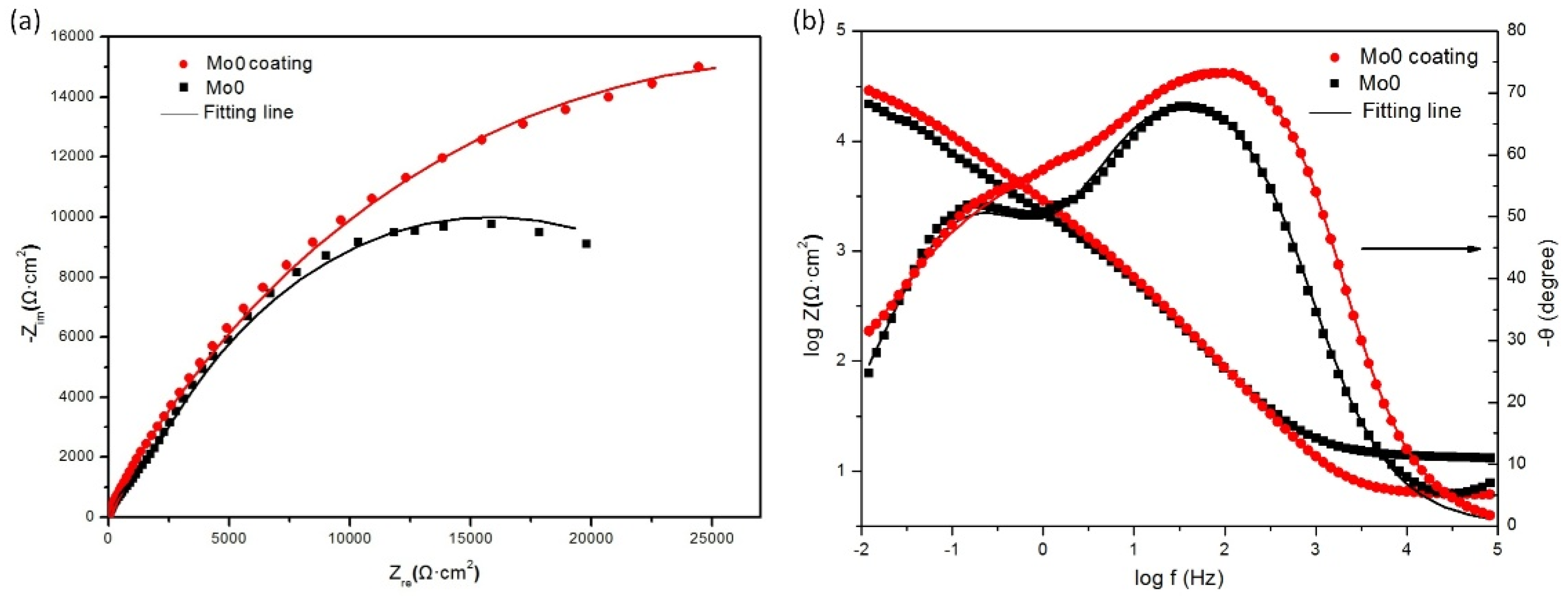
| Mo0 coating | 14.11 | 2.58 | 0.89 | 5.90 | 0.80 | 0.88 | 7.52 | 14.28 | 33,061 |
| Mo0 bulk | 13.33 | 5.34 | 0.84 | 0.27 | 1.34 | 0.74 | 2.70 | --- | 29,700 |
| Samples | Ecorr (VSCE) | Icorr (A/cm2) | Epit (VSCE) | Eprot (VSCE) | Ipass (A/cm2) | Epit − Ecorr (VSCE) | Epit − Eprot (VSCE) |
|---|---|---|---|---|---|---|---|
| Mo23 coating | −0.64 | 5.19 × 10⁻⁶ | 0.21 | −0.15 | 3.31 × 10⁻⁵ | 0.85 | 0.36 |
| Mo0 coating | −0.66 | 2.68 × 10⁻⁶ | 0.13 | −0.19 | 3.02 × 10⁻⁵ | 0.79 | 0.32 |
| Coating | Rs (Ωcm2) | CPEf | Rf (104 Ωcm2) | CPEdl | Rct (104 Ωcm2) | Rsp (Ωcm2) | Rp (Ωcm2) | ||
|---|---|---|---|---|---|---|---|---|---|
| (10−5 Ω−1 cm−2 sn) | n | (10−4 Ω−1 cm−2 sn) | n | ||||||
| Mo0 coating | 14.11 | 2.58 | 0.89 | 5.90 | 0.80 | 0.88 | 7.52 | 14.28 | 33,061 |
| Mo23 coating | 13.59 | 3.62 | 0.77 | 4.33 | 6.10 | 0.86 | 7.11 | 13.29 | 26,911 |
Disclaimer/Publisher’s Note: The statements, opinions and data contained in all publications are solely those of the individual author(s) and contributor(s) and not of MDPI and/or the editor(s). MDPI and/or the editor(s) disclaim responsibility for any injury to people or property resulting from any ideas, methods, instructions or products referred to in the content. |
© 2024 by the authors. Licensee MDPI, Basel, Switzerland. This article is an open access article distributed under the terms and conditions of the Creative Commons Attribution (CC BY) license (https://creativecommons.org/licenses/by/4.0/).
Share and Cite
Shu, X.; Wang, H.; Zhao, J. Microstructures and Corrosion Behaviors of Non-Equiatomic Al0.32CrFeTi0.73(Ni1.50−xMox)(x = 0, 0.23) High-Entropy Alloy Coatings Prepared by the High-Velocity Oxygen Fuel Method. Coatings 2024, 14, 907. https://doi.org/10.3390/coatings14070907
Shu X, Wang H, Zhao J. Microstructures and Corrosion Behaviors of Non-Equiatomic Al0.32CrFeTi0.73(Ni1.50−xMox)(x = 0, 0.23) High-Entropy Alloy Coatings Prepared by the High-Velocity Oxygen Fuel Method. Coatings. 2024; 14(7):907. https://doi.org/10.3390/coatings14070907
Chicago/Turabian StyleShu, Xiaoyong, Hao Wang, and Jianping Zhao. 2024. "Microstructures and Corrosion Behaviors of Non-Equiatomic Al0.32CrFeTi0.73(Ni1.50−xMox)(x = 0, 0.23) High-Entropy Alloy Coatings Prepared by the High-Velocity Oxygen Fuel Method" Coatings 14, no. 7: 907. https://doi.org/10.3390/coatings14070907
APA StyleShu, X., Wang, H., & Zhao, J. (2024). Microstructures and Corrosion Behaviors of Non-Equiatomic Al0.32CrFeTi0.73(Ni1.50−xMox)(x = 0, 0.23) High-Entropy Alloy Coatings Prepared by the High-Velocity Oxygen Fuel Method. Coatings, 14(7), 907. https://doi.org/10.3390/coatings14070907