Review

Research Progress on Numerical Simulation of the Deposition and Deformation Behavior of Cold Spray Particles

1
College of Materials Science and Engineering, Hunan University, Changsha 410082, China
2
AECC Hunan Aviation Powerplant Research Institute, Zhuzhou 412002, China
3
Department of Materials Science and Engineering, The State University of New York (SUNY) Stony Brook, New York, NY 11794, USA
*
Authors to whom correspondence should be addressed.
Coatings 2024, 14(7), 913; https://doi.org/10.3390/coatings14070913 (registering DOI)
Submission received: 25 June 2024 / Revised: 15 July 2024 / Accepted: 19 July 2024 / Published: 21 July 2024

Abstract

:
It is of significant theoretical and practical value to study the deposition process and deformation behavior of cold-sprayed particles to find the deposition mechanism of cold-sprayed coatings, further improve the coating performance, and expand its application scope. However, observing the deposition process and particle behavior through experiments is difficult due to the brief deposition duration of cold spray particles. Numerical simulation offers a means to slow the deposition process and predict the critical velocity, deformation behavior, bonding mechanism, and residual stress of cold-sprayed particles. This paper uses finite element analysis software, including ANSYS LS Dynamic-2022 R1 and ABAQUS-6.14, alongside various prevalent finite element methods for numerically simulating cold spray particle deposition. These methods involve the Lagrange, Euler, arbitrary Lagrange-Euler (ALE), and Smoothed Particle Hydrodynamics (SPH) to investigate the cold spray particle deposition process. The recent literature primarily summarizes the simulation outcomes achieved by applying these methodologies for simulating the deposition process and deformation characteristics of different particles under varying cold spraying conditions. In addition, the reliability of these simulation results is analyzed by comparing the consistency between the simulation results of single-particle and multi-particle and the actual experimental results. On this basis, these methods’ advantages, disadvantages, and applicability are comprehensively analyzed, and the future simulation research work of particle deposition process and deformation behavior of cold spraying prospects is discussed. Future research is expected to provide a more in-depth study of the micro-mechanisms, such as the evolution of the inter-particle and internal organization of the particles, near the actual situation.

1. Introduction

Thurston et al. developed cold gas spraying (CS). This innovative technique has significant practical implications, as it allows for producing high-quality coatings with improved performance and a wide range of applications [1]. At the beginning of the twentieth century, metal powders were accelerated by pressurized gas to 300 m/s and found to be able to produce deposits on impact with the substrate. Then, in the 1950s, the Rocheville technique became a breakthrough by accelerating metal powders to unattainable speeds utilizing a gas flow through a De-Laval spout. In the 1980s, the Russian Academy of Sciences [2] Institute of Theoretical and Applied Mechanics developed a new coating process that accelerates less than 100-micron diameter particles into high-pressure airflow. The supersonic airflow speeds up to 400–1200 m/s, causing particle impact on the substrate. Severe plastic deformation occurs when the particle velocity exceeds a certain critical value, resulting in the formation of particle deposition on the surface of the base material. The traditional process of CS is shown in Figure 1 with a compressed gas (commonly air, nitrogen, and helium or a mixture of the latter two gases). Cold spraying is divided into high-pressure (>1.6 MPa) and low-pressure (<1.6 MPa) cold spraying based on the driving gas pressure.
Figure 1 shows the low-pressure and high-pressure cold spraying where compressed gas is heated and fed into the Rafael tube, and through the acceleration effect of the Rafael tube, it accelerates the gas flow. The low-pressure cold spraying powder delivery port is in the expansion section of the Rafael tube throat. It relies on the negative pressure generated by the accelerated airflow to be sent to the powder feeder to suck the powder into the high-speed movement of the airflow and accelerated, while the high-pressure cold spraying system of the driving gas and the powder carrier gas is separate. The powder delivery port is in the compression section of the Rafael tube. The powder carrier gas pressure needs to be higher than the pressure of the driving gas, i.e., the high-pressure powder carrier gas feeds the powder into the compression section of the throat of the Rafael tube, which is accelerated by the driving gas. Whether it is low-pressure or high-pressure cold spraying, the particles need to be accelerated above the critical velocity of the powder to cause it to be deposited and continuously stacked to form a cold spray coating [3]. CS belongs to the thermal spraying of a solid-state process that is different from other technologies. The traditional thermal spraying process exists in the grain growth, chemical reaction, thermal shrinkage, thermal residual stresses, and other [4] phenomena, which do not exist in CS, mainly because CS has a processing temperature lower than the melting point of the particles and a higher processing speed, which effectively reduces the adverse effects of temperature. For example, oxidation, residual stresses, phase transitions, and other organizational changes can result in virtually oxygen-free coatings or deposits [5]. Moreover, because CS can coat substrates <1 mm thick without damaging the substrate, it is well suited for temperature- and oxygen-sensitive [6] materials and repairing damaged metal parts and equipment in industrial production. In recent years, the application of cold spraying in additive manufacturing has become widespread. It is commonly used in aerospace, automotive, and marine transportation [7] because it protects the substrate from harsh operating environments such as oxidative phase change and seawater corrosion. Although many numerical simulations and experimental studies have been performed on the CS coating bonding mechanism, there is still no consistent explanation of the bonds and mechanisms. As shown in Figure 2, the CS coating bonding mechanism is divided into two major schools of thought.
The first type of coating bonding proposed by Assadi et al. [10] is metallurgical bonding due to metal jets caused by the adiabatic shear instability of ASI. In 2003, Assadi et al. [11,12] found through numerical simulation of cold spraying experiments that particles bond to the substrate when they exceed a certain velocity during spraying; this velocity is called the critical velocity, i.e., the minimum velocity for the formation of the coating. A pressure field is generated when particles strike the substrate at or above the critical speed. It propagates at the contact point between the particles and the substrate. In contrast, the pressure field generates a shear load, which leads to a localized shear strain, giving the material a horizontal force in the horizontal direction to induce the material to move. Under certain conditions, ASI causes the material to flow outward in a vicious manner when the thermal softening resulting from particle impact exceeds the local strain and strain rate hardening, resulting in a metallic jet (Figure 2a). Hassani et al. [9] proposed another bonding mechanism, who argued that hydrodynamic plasticity is the main principle of coating bonding, this is because they removed the thermal softening in the intrinsic relationship based on Assad’s study and found that it was still possible to observe the jet phenomenon after particle impact on the substrate (Figure 2b). Hence, they argued that the formation of jets is not linked to thermal softening. At the same time, they concluded that the formation of jets is not directly associated with thermal softening. In conclusion, they believe that the interaction between the shock wave generated by the particle impacting the substrate and the contacting edge portion of the particle is the main cause of metallic jets. There are various factors affecting whether the particles can be successfully combined with the substrate in the CS process, in addition to the mechanism of the coating itself, which is also affected by many factors, including the particle and substrate material properties, substrate roughness, and spraying conditions such as the temperature and type of processing gases, the most important of which is the deformation of the particles themselves. Furthermore, due to the almost instantaneous collision of particles, significant plastic deformation, and large strain rate in the cold spray process [13], it is difficult to directly observe the deformation of particles in the collision process and deposition behavior in an experiment. This can only be observed through a microscope. The deformation of the particles that are coated after the analysis of the solid results is often controversial. So, many researchers have investigated the critical velocity of particles in the CS process and the deformation and deposition behavior through numerical methods such as finite element simulation, in which the commonly used finite element software is ANSYS-Ls-dyna-2022 R1, ABAQUS-6.14, etc. To enable readers to understand the finite element simulation process better, we express the tedious simulation process in a simplified way through a flowchart, as shown in Figure 3. The diagram illustrates the general flow of the finite element from the very beginning of the 2D or 3D model selection to the intrinsic model, followed by the input of material parameters, the selection of the intrinsic model and the finite element simulation method, immediately followed by meshing and cell size adjustment. Finally, after the computation, we obtain its PEEQ, temperature map, particle/substrate energy curve, and the residual stress distribution through the post-processing. Therefore, in this paper, we will comprehensively discuss the research progress of numerical simulation methods at home and abroad from the perspective of numerical simulation, followed by an overview of the limitations of the research work in this field and some outlooks on future research work.

2. Commonly Used Material Constitutive Models and Alloy Property Parameters for Cold Spraying

2.1. Material Modeling Methods and Parameters of Commonly Used Cold Spraying Materials

The following typical methods are used to observe the deformation of different cross-sections better when the particles impact the substrate and to shorten the calculation time: (1) The two-dimensional axisymmetric model is used for the simulation experiments [14,15,16]. A typical 2D model [17] is shown in Figure 4a, where the particle diameter is 36 μm, the length and height of the substrate are 360 μm and 180 μm, respectively, and the dimensions of the mesh size are uniformly 0.5 μm. (2) The three-dimensional 1/2 or 1/4 symmetric model is used. The substrate region will be divided into two zones, where the mesh density of the contact zone is larger and the mesh density of the non-contact zone is smaller [18]. The typical 1/4 model diagram is shown in Figure 4b. The meaning of * in Figure 4b is multiplication, the size of the contact part is 2.5 times the diameter of the particles, and the diameter and height of the non-contact part are 12.5 times the diameter of the particles.
The typical properties of powders and substrates are needed to simulate cold spray particle deposition behavior. The metal or alloy materials commonly used for cold spraying and their performance parameters are shown in Table 1 [15,19,20,21,22].

2.2. Common Constitutive Models of Materials

In cold spray (CS), the high-velocity impact of particles on the substrate results in significant plastic deformation, high strains, and temperatures in both the sprayed material and the substrate. Therefore, the conventional plastic stress-strain values are insufficient for numerical simulations of CS and necessitate the development of material-specific intrinsic models [23], such as the JC and ZA models.

2.2.1. Johnson–Cook Plasticity (JC) Model

In the CS process, the deposition process is considered adiabatic due to the extremely short collision time of the particles, and its temperature increase is caused by plastic deformation. Considering that the material has a large strain rate, the Johnson–Cook model [24], a semi-empirical model, integrates the effects of strain hardening, strain rate strengthening, and temperature softening. It is widely used due to its simplicity, ease of implementation, and relative accuracy. Its Equations (1) and (2) are shown below:
σ = A + Β ε p n 1 + C l n ε * 1 T * m
T * = 0 T T r / T m T r 1 T < T r     T r T T m T m < T
where σe is the equivalent stress; A, B, n, C, m are material constants determined by the nature of the material itself; εp is the effective plastic strain (PEEQ); ε* is the effective plastic strain rate relative to the reference strain rate εp/ε*; T* is homologous temperature, Tm is the melting point of the material, and Tr is the reference temperature (generally taken as the room temperature 298 K).

2.2.2. Zerilli–Armstrong (ZA) Model

ZA is based on dislocation mechanics used to describe the ontological relationships of flow stress in metals [25]. Its model simulates the plastic behavior of materials, and a modified version of it can be used to describe flow stress at high temperatures [26]:
σ = C 1 + C 2 ε n exp C 3 + C 4 T * + C 5 + C 6 T * ln ε *
where C1, C2, C3, C4, C5, C6, and n are material constants; T* = TTr, T is the absolute temperature, and Tr is the reference temperature; and ε* is the equivalent plastic strain rate normalized concerning the reference strain rate.

2.2.3. Preston–Tonks–Wallace (PTW) Model

The PTW model is mainly applicable to the plastic flow of metals under high-velocity impact or explosive loading, where the flow stress is defined as follows [27]:
σ = 2 τ ^ s + α ln 1 ϕ exp δ θ ε α ϕ G p
α = s 0 τ ^ y p p t w , δ = τ ^ s τ ^ y α , ϕ = exp δ 1
where τ ^ s is the normalized work-hardening saturation stress, τ ^ y is the normalized yield stress, s0 is the saturation stress at 0 K, pptw is the strain-hardening constant, θ is the strain-hardening rate, and ε is the equivalent plastic strain.

2.2.4. Mechanical Threshold Stress Model (MTS)

MTS is a physically based model for high strain rate and high deformation simulations where the shear modulus is defined in MTS as follows [28]:
G p T = G 0 D exp T 0 T 1
G0 in Equation (6) is the shear modulus at 0 K; D is the material constant; T0 is the temperature material constant; and T is the material temperature. The work-hardening saturation and yield stresses are derived from the following [27]:
τ ^ s = max s 0 s 0 s e r f κ T ^ ln γ ε ˙ ε ˙ p , s 0 ε ˙ p γ ζ ˙
τ ^ y = max y 0 y 0 y e r f κ T ^ ln γ ξ ˙ ε ˙ p , min y 1 ε ˙ p γ ζ ˙ y 2 , s 0 ε ˙ p γ ζ ˙ β
where T ^ = T/Tm, Tm is the melting temperature; s is the saturation stress near the melting temperature, s0 is the saturation stress at 0 K; κ is the temperature-dependent constant; β is the high strain rate exponent; γ is the strain rate-dependent constant; εp is the plastic strain rate; y0 is the yield stress constant at a temperature of 0 K, y is the yield stress constant near the melting temperature, y1 is the medium strain rate constant, and y2 is the medium strain rate exponent; and ζ ˙ is an unnamed parameter.

2.2.5. Modified Johnson–Cook Model

This model solves the problems encountered in the original JC model species, and the flow stresses at their high strain rates are shown in Equations (9) and (10) [29]:
σ = A + B ε n 1 + C ln ε ˙ p ε ˙ 0 ε ˙ p ε ˙ c D 1 T T r T m T r m
D = 0 , ε ˙ p < ε ˙ c x , ε ˙ p ε ˙ c a n d   ε ˙ c = y s 1
where D is a non-zero parameter when the plastic strain rate is equal to or greater than the critical strain rate ε ˙ c (y) and ε ˙ 0 is the reference strain rate, y is a constant, s means time A, B, n, C, and m are material constants determined by the nature of the material itself.
In addition, the linear equation of state is generally used as the equation of state of the material, and the thermal–structural coupling algorithm is used to determine the generation and distribution of 90% of the plastic work transformed into heat under adiabatic shear. The Mie–Gruneisen (EOS) equations [30] are used to describe the shockwave effect of the material as well as its elastic behavior during plastic deformation at elevated temperatures and high pressures, which is shown in Equation (11):
p = ρ 0 C 0 2 η 1 S η 2 1 Γ 0 2 + Γ 0 ρ 0 Ε m
where ρ0 is the initial density and p is the current density; C0 is the speed of sound; Γ0 is a material-dependent constant; S is the coefficient of the linear Hugoniot formula; Em is the internal energy per unit volume; and η = 1−ρ/ρ0 is the standard volumetric compressive strain.

3. Common Finite Element Simulation Software and Methods for Simulating Particle Deposition and Deformation Behavior in Cold Spray Coating

So far, most of the simulation research work has been carried out based on the finite element method, and the earliest finite element simulation method used was the Lagrange method [31], which performs simulation calculations by building a model where the mesh varies with the material. The smaller the mesh size, the more accurate the simulation results. Moreover, this method is faster in calculation and can simulate the changes in temperature and residual stresses between the substrate and the particle interface. Yin et al. [32] used the finite element method to study the effect of the interaction between particles on the formation of coatings and found that when the parallel distance between particles is short, the particles will be continuously compressed, thus reducing the gap between them. Due to the tamping effect, the continuously impacted particles will lead to a denser coating interior. The simulation results are in high agreement with the experimental results of Li et al. [33]. As shown in Figure 5, it is obvious that the region near the surface of the coating shows more porous microstructural features than the interior of the coating.
However, the Lagrange method has certain shortcomings; when the particle velocity is large, it will lead to severe deformation of the mesh, which will terminate the calculation [34,35], and considering that when the particles hit the substrate, the elastic storage energy of the substrate exceeds the elastic energy of the particles, which will result in the rebound of the particles. Since this adversely affects the accuracy and convergence of the model in the region of severe deformation, various simulation methods, such as Euler, ALE, and SPH methods, as shown in Figure 6, have been derived since then. Among the different simulation methods for solving complex nonlinear problems, finite element analysis simulation software, such as ABAQUS-6.14, ANSYS-Ls-dyna-2022 R1, etc., are commonly used [4].

3.1. ALE Method

The ALE method, also known as the arbitrary Lagrange–Euler method, differs from the traditional Lagrange method in that it is less affected by the mesh size because its adaptive mesh changes do not cause the computation to be terminated due to severe particle deformations, and it is computationally faster than the Lagrange method [17]. Therefore, it is preferred when it comes to studying particle extreme deformation. In 2006, Wen et al. used the ALE method to numerically simulate the experiment of spraying Al particles with Al particles, revealing the deposition characteristics of Al powder and the influence of the surface oxide film on the particle deposition and bonding strength by simulating the deformation behavior of the particles with the substrate after spraying [14]. They discovered that the deformation of the particles was suppressed with the increase in the thickness of the oxide film, and the formation of the metal jets at the local interfaces became difficult, which may affect the bonding strength of the particles to the substrate. This is mainly related to the bonding mechanism of the coating; the particles hit the substrate at high speed under the huge impact force, and the oxide film on the surface of the particles is destroyed, exposing the fresh, unoxidized surface to be combined with the substrate and the previous oxide layer to be extruded in the form of jets. To study the particle/substrate interaction, Yu et al. [4] conducted a simulation study of 6061Al coatings prepared by cold spray additive manufacturing using the finite element method. By comparing the SEM plots of 6061Al with the plots of simulation experimental results such as von Mises stress, PEEQ, and temperature distribution, it is found that the maximum equivalent stress occurs at the contact interface between the particles and the substrate, as shown in Figure 7f, with a peak value of about 406 MPa and a maximum PEEQ of about 14.29. The presence of a maximum equivalent force increases thermal softening [36], leading to the material’s plastic flow. Moreover, the particles are partially embedded in the substrate due to the low mass density of the aluminum particles. This is in keeping with the observation of jet-like features in the peripheral region of the particles in Figure 7k and embedded in the substrate.
Wang et al. used the ALE method for multi-particle simulation of particles. They found that the distribution of residual stress σX in multi-layer CS particle deposition can be regarded as a synergistic effect of collisions between particles, interactions between particles in the same layer, and interactions between particles in different layers [17]. And, due to the synergistic effect, the tensile stress region moves from the substrate to the deposited layer as the deposition thickness increases, as shown in Figure 8f. Wang et al. used the ALE method to compare the experimental result plots of the Cu-sprayed Al substrate at 550 m/s with the simulated result plots, as shown in Figure 9, and found that the results of the two plots coincide with each other [15].
However, most results indicate that the regular jet shapes obtained from the ALE method’s simulation results do not correspond to the experimentally obtained reality, which can be attributed to the interpolation error caused by the adaptive mesh algorithm [37,38,39]. The method normalizes the mesh undergoing extreme deformations to avoid severe distortions and standardizes the physical quantities contained in the mesh, thus leading to numerical distortion of the results. Nevertheless, it is possible to adjust the parameters employing the ls-dyna pre-post to optimize the jet morphology and bring it closer to realistic conditions.

3.2. SPH Method

The SPH method is another meshless form of the Lagrange method, where elements are discretized into particles. For the SPH numerical simulation method, extreme mesh distortions can be avoided since it is not a mesh-based numerical method. The method focuses on a continuous material represented by a series of particles that carry certain fundamental physical quantities that can characterize the material used and originally developed by Gingold et al. [40] to solve astrophysical problems [41]. Then, it was applied to engineering problems; however, with its development, it was found that severe deformations can also be experienced during high-speed impacts [16], and therefore can be applied to areas such as CS numerical simulations. Michael Saleh et al. [42] conducted a groundbreaking analysis of CS particle deposition using innovative SPH modeling. This unique approach allowed them to demonstrate particle–particle interactions and the nature of inter- and intra-layer adhesion during deposition. The research’s practical implications are significant, as it reveals that the deposition bonding mechanism, when individual particles are bonded to neighboring particles through thin bands of molten material, can be considered a “micro-welding”. This is a departure from the conventional understanding of a thermos–metallurgical bonding mechanism, as the origin of the heat source is dynamic. Lemiale et al. [43] also adopted the SPH modeling approach to simulate the impact of a single Cu particle on a planar Cu substrate. Their findings underscore the significant effect of temperature and strain rate in CS, challenging the assumption that cold-sprayed materials are at room temperature at the time of impact. This new understanding can potentially enhance the quality and performance of cold-sprayed materials, as the model outlined in this experiment can help those involved better understand the influence of the initial impact parameters on the final properties of the coatings produced.
In Li et al. [44], the SPH method simulated the CS process of Cu particles impacting a smooth Cu surface. Their study provided a comprehensive understanding of the collision behaviors of cold spraying and demonstrated the practical implications of the SPH method. The results of their simulation study, which coincided with those simulated by the Lagrange method, as shown in Figure 10, underscored the potential of the SPH method to enhance our understanding of the cold spraying process, thereby contributing to the advancement of materials science. Moreover, this study also discovered that the particles do not rebound but adhere to the substrate after impact, which may be related to the powerful ability of the SPH method to capture interfacial features and deal with the free surface. Abba A et al. [45] used a combination of two finite element simulation methods, i.e., SPH discretization for the granular region and Lagrangian discretization for the basal region, to investigate the particle/particle microstructure and microstructure evolution during the continuous deposition of multiple particles. The results show that the adiabatic process of particle deformation due to temperature increase leads to thermal softening, as shown in Figure 11b, resulting in highly localized plastic deformation at the jet interface, and the deposition simulations of multilayered particles show complex lamellar structures corresponding to those in Figure 11d [46]. This suggests that the multi-particle simulation can predict a variety of fundamental features of particle deposition, such as particle size, deformation morphology, and microcracks, during actual experiments. Balachander et al. [47] conducted a comprehensive study, performing three-dimensional single-particle and multi-particle simulations of the cold spraying process using the SPH method. Their findings, particularly the contours of the effective plastic strain and temperature of a single particle impacted at 150 ns, were in line with Assadi et al. [10] after cold spraying. This alignment with previous research validated their findings and underscored the SPH method’s potential in improving our understanding of the cold spraying process.
The SPH method applied to the numerical simulation of CS technology has the following advantages: 1. it can better deal with the advection of the material, unlike the Euler and CEL methods, where there is no material motion through any element; 2. it can effectively deal with almost all the complex geometries, which avoids the need to design segmented models; 3. it can be used to carry out the computational solution for extreme deformations, which avoids computational due to the extreme deformation of the grid termination problems; 4. the difference between the Lagrange method explicitly tracks the contact interface, avoiding the problem of contact algorithm selection; and 5. the difference between the SPH method and the ALE and Euler methods is that they ensure the conservation of energy and momentum of the simulation process. In contrast, the advection of the material in the other two methods may lead to energy loss. However, the SPH method has drawbacks, such as tensile instability and the absence of connections between particles, which may result in serious numerical problems [47,48,49].

3.3. Euler Method

The Euler method, initially proposed by Li et al., was a significant breakthrough in addressing the issue of computational termination due to extreme mesh deformations in the Lagrange method. This method views the entire mesh as a network of two overlapping meshes, with nodes and cells fixed in space. The material flows through the cells, and the mesh remains stationary, allowing continuous material flow [34]. The nodes and the cells are fixed in space, the material flows through the cells, the mesh is fixed in space, and the material flows through the cells.
Li et al. [50] experimentally compared the two simulation methods, Euler and Lagrange, revealing that the particle deformation patterns calculated by the Euler method were closer to the actual situation than the Lagrange method. In addition, Schmidt et al. [51] also found that both of them match in morphology by comparing the results of the collision between Cu balls and 20 steel with the simulation results obtained by the Euler simulation method, as shown in Figure 12. Thus, this further illustrates the feasibility of the Euler method to study the deformation behavior of CS. Notably, Li et al. [52,53], in an innovative application, used the jet morphology in the Euler model to predict the critical velocity of the particles. They determined that the criterion for the critical velocity of the particles is the generation of jets at the contact interface between the particles and the substrate and the existence of the maximum equivalent plastic strain value within a certain range. They successfully predicted that the critical velocity of the Cu/Cu system is about 300 m/s, as illustrated in Figure 13 and Figure 14.
Yin et al. [48] simulated the multi-particle impacted substrate using the Eulerian and Lagrange methods, respectively, as shown in Figure 15a,b. They found that at 140 ns and 190 ns, the bottom particles were compacted into irregular shapes due to the tamping effect of the particles’ continuous impact. An obvious plastic flow was observed in the contact region between the particles, leading to banded jets at the edges of the particles. This phenomenon may enhance the bonding force between the coated particles, which is in high agreement with the phenomena observed in the SEM images in Figure 15c,d [54]. In addition, when the impact time reaches 190 ns, the particles separate from each other in the results of the Lagrange model. In contrast, at 140 ns, the characteristics of the formed coating remain unchanged. This fact may indicate that the Euler method provides more accurate deformation of individual particles and more accurate coating features regardless of how many particles impact the substrate. Although the Euler method solves the problems of particle rebound and the termination of calculation due to the extreme deformation of the mesh compared with the Lagrange method, there are some defects. For example, Yin et al. found by comparing the multi-particle impact model of the Lagrange method and the Euler method that although the Euler method has high accuracy and stability in simulating the multi-particle impact process of the cold spraying process and is more realistic, there is the problem of adhesion between particles, which makes it impossible to distinguish the interface between particles/particles and particles/substrate [55]. The Euler method suffers from the problem of bonding between particles, resulting in the inability to distinguish the interfaces between particles/particles and particles/substrate. Additionally, the computational speed is slower compared to the Lagrange method.

3.4. Other Common Methods

Regarding the finite element method, apart from the numerical simulation methods such as Lagrange, Euler, and ALE methods mentioned above, the CEL method and the MD method are also worth mentioning in the context of the finite element method. Among them, the CEL method combines the Lagrange and Euler formulations mainly developed based on the Euler method [56], which solves the problem of excessive mesh distortion and unrealistic jet shapes as a direct result of a physically improved fluid-like particle behavior. Despite its advantages, there are some defects [57]: 1. additional computational work is required in maintaining the material interface and reducing numerical diffusion; 2. the particle velocity can still terminate the computation due to severe deformation of the substrate when it is too large; and 3. it still does not solve the problem of particle rebound. However, Nélias D et al. [58] found through simulation experiments that compared to other numerical simulation methods (Lagrange, arbitrary Lagrange–Euler, and SPH), it is overall more accurate and robust in the high strain rate deformation mechanism and that the region of high strain rate plastic deformation is located mainly at the base of the particles and at a depth of a few micrometers below the substrate surface. Additionally, they discovered the initial temperature of the particles has more influence on the equivalent plastic strain than on the localized temperature increase in the substrate. There is still no homogeneous explanation for the bonding mechanism between particles and substrates in the CS process. Since the bonding in the CS process occurs at the molecular level, the MD method is ideal for simulating the bonding behavior at the interface. Fewer research articles have been published on applying the MD method to CS. Malama T et al. employed the MD method to simulate the effect of impact velocity on the coating process of titanium and nickel particles on a titanium substrate in the CS process. They found that higher impact velocities resulted in a stronger particle–substrate interface between the particles and the substrate [59]. Similarly, Aneesh Joshi et al. used the MD method to study the bonding mechanism of Cu nanoparticles on Cu substrates during the CS process and the effect of process parameters on the deposition of materials in the CS process. They found that keeping the particle impact velocity in a certain range during the CS process results in high-quality coatings [60]. Moreover, the MD simulation study is consistent with the previously reported finite element simulation results, confirming that shear instability, adiabatic softening, and interfacial jet formation at higher impact velocities occur at the particle–substrate interface. The MD method is used to study the nanometer level. In contrast, the commonly used finite element method is applied to the micrometer level; the advantages, disadvantages, and characteristics of all the finite element methods mentioned above are summarized in Table 2; it is believed that a clearer understanding of the deformation behavior of the particles and the substrate can be obtained if the two methods are combined in the research work.

4. Factors Influencing the Simulated Depositional Binding and Deformation Behavior of Particles

Many factors influence the cold spray deposition process. Understanding the primary and secondary influences of these factors will help us better understand the combination mechanism of the cold spray deposition process. Therefore, this chapter summarizes the factors affecting the cold spray deposition process, as shown in Figure 16.

4.1. Material Characteristics

4.1.1. Particle Morphology

The critical velocity is determined by the material properties and related to the material size. Some studies indicate that for spherical particles with a diameter of 25 μm, the critical velocities of Cu powder on a Cu substrate and 316 L stainless steel powder on a 316 L stainless steel substrate were 500 m/s and 650 m/s, respectively, as shown in Figure 17 [50]. The studies also found that the critical velocity decreased sharply when the particle size increased to 50 μm. However, the effect of particle size becomes negligible when the particle size exceeds 50 μm. Other researchers have also demonstrated that the critical velocity of smaller-sized particles is higher than that of larger-sized particles of the same material, i.e., the critical velocity decreases as the particle size increases, but the deformation characteristics remain qualitatively unchanged [63,64,65,66]. It is important to note the powder size must be within a certain range. Typically, the diameter range is between 10 µm and 100 µm [31]. This is because powder sizes outside this range are difficult to push by accelerating gases and thus cannot be deposited [67], the common particle size range for most metallic materials is 20–60 µm.
The morphology of the powder during the cold spraying process also greatly influences the coating properties, which determine the distribution of particles in the coating, the bonding strength, the physicochemical properties, etc. By simulating spherical and coral-shaped titanium powders, MacDonald et al. and Luo et al. [68] found that coral-shaped powders collapsed after undergoing severe plastic deformation, thus forming a coating with a greater compositional density than that of spherical powders, as shown in Figure 18 [69]. A similar trend was in dendritic powders, where dendritic nickel powders produced denser deposits than spherical powders.
In addition, Munagala et al. [70] found that various powder shapes exhibit different dispersion and fluidity during spraying, affecting the prepared coatings’ thickness and uniformity. They also pointed out that the powder shape affects the bonding strength and wear resistance of the sprayed coatings to a certain extent. Moreover, Xiang et al. [71] conducted cold spraying experiments with different powder morphologies and found that they significantly affected the hardness and wear resistance of the coatings. Overall, powder morphology primarily affects the final properties of the coating by controlling the shape and quantity of pores post-deposition.

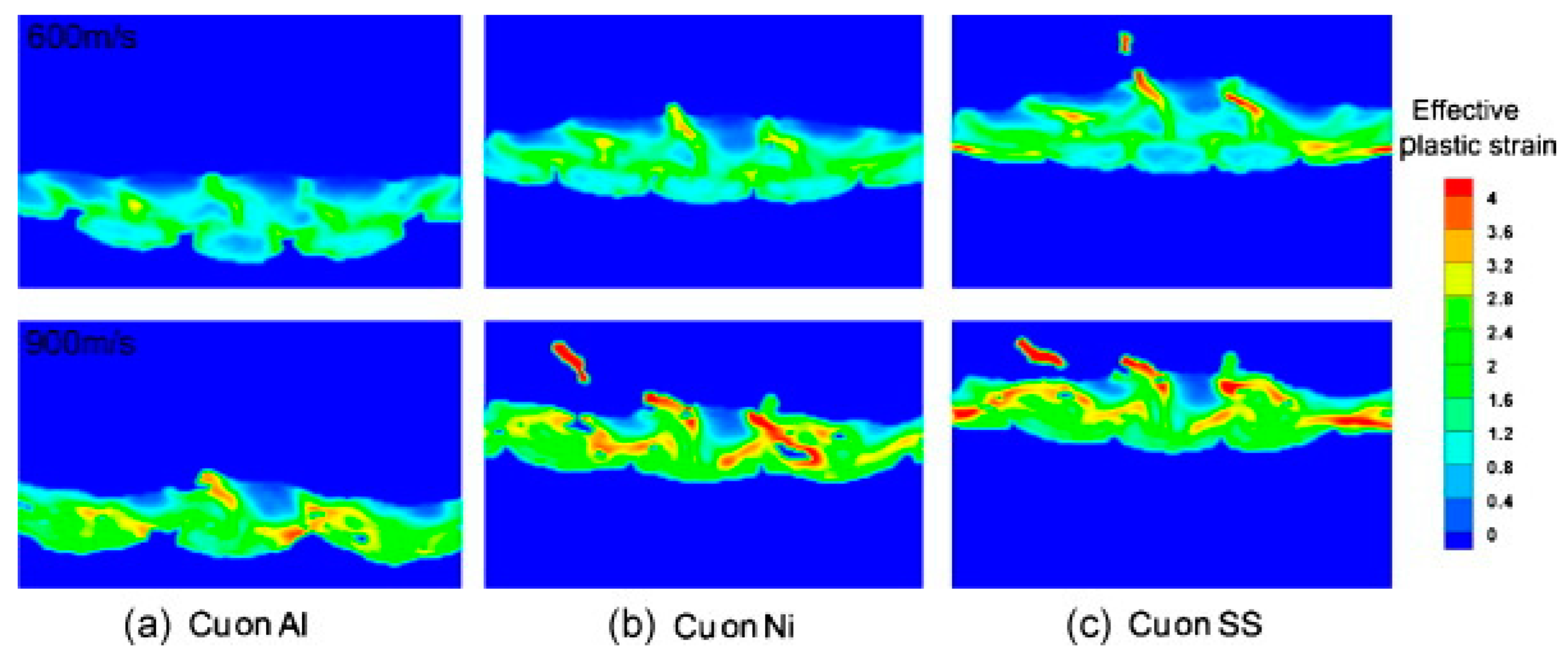
4.1.2. Particle/Substrate Hardness

The degree of softness or hardness of the particles and the substrate also affects their subsequent deformation behavior. SHOU et al. [72], after comparing Cu/Al, Cu/Ni, and Cu/Steel, found that the effective plastic deformation of particles inside the coatings formed on the Al substrate was less than the other two cases, as shown in Figure 19. This suggests that compared to the hard substrate, the soft substrate can make the subsequent particles deform less. The main reason for the difference in the degree of particle deformation is the discrepancy in substrate hardness. When the substrate hardness is higher than that of the particles, the subsequent particle collisions and, thus, the buildup of the coating absorbs all the kinetic energy, resulting in large deformation of the particles, while the substrate is almost undeformed.
Therefore, the differences in the hardness of particles and substrates can affect the formation of the coating for metals like Al and Mg, which are more plastic and malleable. When the impact to the hard surface of the substrate produces a greater degree of deformation and jet and due to the substrate of the contact area become larger, reducing the elasticity of the particles, the particles bond better with the substrate combination, but are also more likely to produce mechanical interlocking and metallurgical bonding phenomenon. This makes it easier to produce mechanical interlocking and metallurgical bonding phenomena.

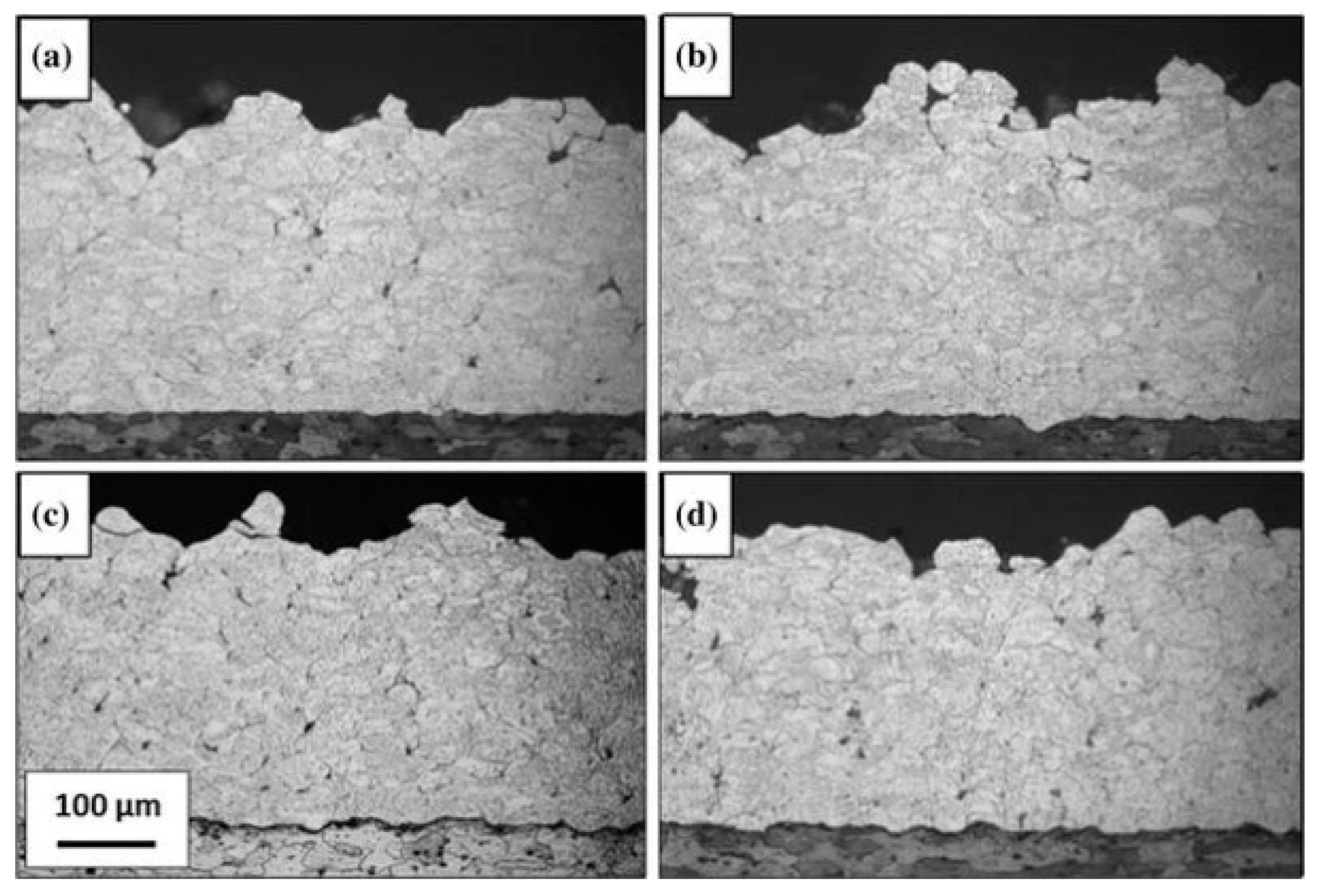
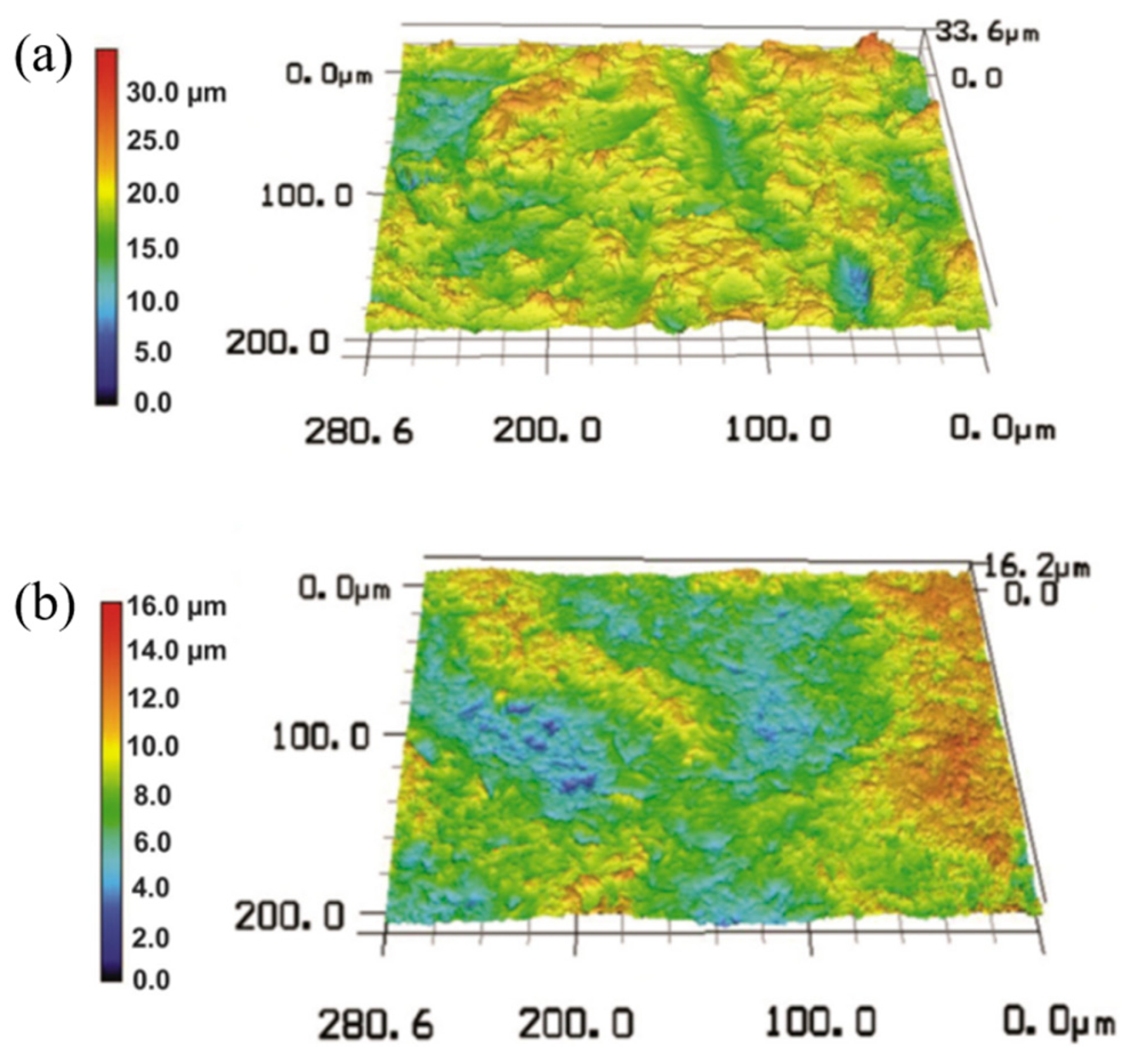
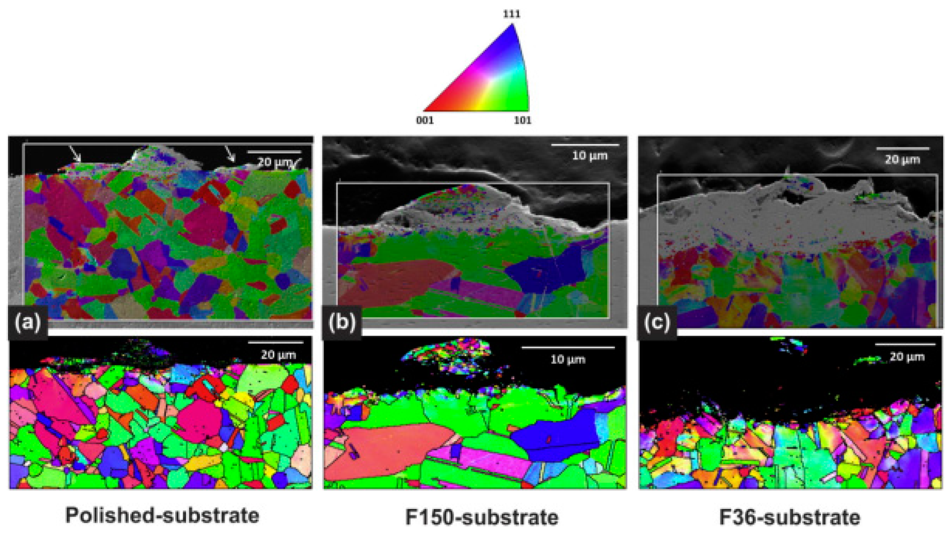
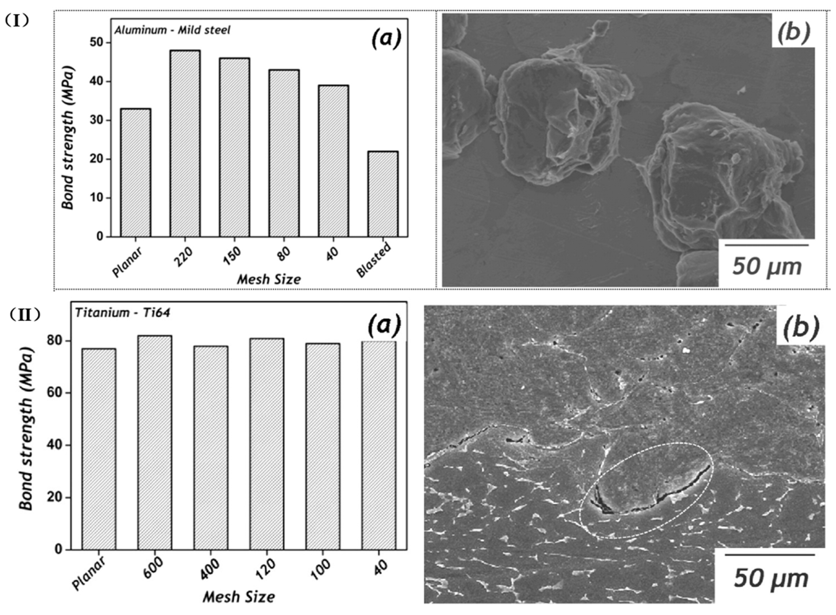
4.1.3. Substrate Roughness

It is widely known that the surface roughness of the substrate plays a crucial role in particle–substrate bonding [73]. Research findings have underscored the significant role of substrate roughness in particle–substrate bonding. Notably, substrates with higher surface roughness have been shown to exhibit superior coating adhesion compared to smooth substrates for CS pure aluminum coatings. This was demonstrated in the work of Blochet et al. [74], who investigated the effect of different grades of blasting roughness on the surface treatment from the point of view of the experimental procedure and numerical simulation, respectively, and conducted a separate single pure Al particle on AA2024-T3 substrate impact simulation experiments, depicted in Figure 20 and Figure 21. The findings from these similar simulation experiments also confirmed the importance of substrate roughness and helped to explain the particle bonding mechanism. This could be attributed to higher substrate roughness reducing the contact area to some extent, which increases the contact pressure, increasing localized plastic deformation of the particle, destroying the oxide layer of the particles, thus exposing fresh metal in the particles, and therefore facilitating the metallurgical bonding between the powder particles and the substrate. It is crucial to note that the influence of substrate roughness is not uniform across all layers of the coating. Our research, as demonstrated by Richer et al. [75], has shown that substrate roughness primarily affects the efficiency of particle deposition for the initial layers. This practical implication should be considered in future research and real-world applications, guiding the design and optimization of metal coatings.
Singh et al. utilized Inconel 718 powder to study the deposition behavior of single particles impacted onto substrates with different roughness [76]. Figure 22 shows the surface roughness morphology of different substrates prepared with F-36 and F-150 abrasive grains, respectively. The study revealed that phenomena such as cracking and peeling were observed when the powder was deposited with lower-roughness substrates. However, when interacting with substrates with higher roughness, as shown in Figure 23, EBSD micrographs, where the black portion is the extent of severe deformation and the interaction of the F-36 substrate, are estimated to have a larger black area. Therefore, a higher degree of plastic deformation and mixing of interfacial materials was observed and similar conclusions were drawn.
Kumar S et al. [77] simulate CS deposition on flat surfaces and several substrates with different roughness by the ALE method. They discovered that the roughness of the substrate enhances the deposition characteristics of the powder; for instance, the sandblasted substrate has a higher bonding strength, as shown in Figure 24 (I), which is mainly with the interfacial bonding induced by the adiabatic shear instability due to the rougher edges through the mechanical interlocking to make better bonding with the aluminum fragments, which means the solid bond strength is higher. Figure 24 (II) shows the cross-section of the coating deposited on the scraped substrate using a 120-mesh sieve, which corresponds to the peak and trough positions in the coating. However, Jiang et al., using finite element simulations, made the opposite conclusion in their study of titanium alloys [78].
Different substrate pretreatment methods and materials will have different degrees of influence on the coating formed after cold spray deposition. For materials with low strength and good plasticity, increasing the surface roughness of the substrate allows the soft particles to be better embedded in the substrate’s surface, making it easier to form a mechanically interlocking structure and enhancing the bonding of the particles with the substrate. However, increasing the substrate roughness for harder materials such as titanium and titanium alloys can make sputtering during particle deposition difficult, resulting in a coating of lower strength.

4.2. Cold Spray Parameter Factors

4.2.1. Cold Spraying Velocity

Cold spraying velocity is a key factor for successful particle/substrate bonding. Researchers focus on a series of collision phenomena occurring when the particle impacts the substrate surface, related to the particle velocity. Wang et al. simulated the experimental process of single Cu particles by comparing two different numerical simulations, namely the ALE method and the Lagrange method, respectively, at 300 m/s, 500 m/s, and 700 m/s [15]. The effective plastic deformation simulation results are depicted in Figure 25, showing that the deformation degree of particles and substrate in both methods increases gradually with particle velocity. At lower particle velocity, the degree of deformation is similar for both methods; however, at higher particle velocity, the degree of deformation of the particles/substrate simulated by the Lagrange method is larger than that of the ALE method. When the velocity of cold-sprayed particles is low [79], the particles will only erode the surface of the substrate without bonding; when the particle velocity is high, the particles will adhere to the surface of the substrate; the minimum velocity at which bonding of the particles occurs is referred to as the critical velocity of the particles, and when the particle velocity significantly exceeds the critical velocity an erosion effect will occur [80]. Therefore, the successful preparation of coatings requires that the particle velocity be controlled above the critical velocity but without the erosion effect, i.e., Vcritical < VParticle velocity < Verosion.

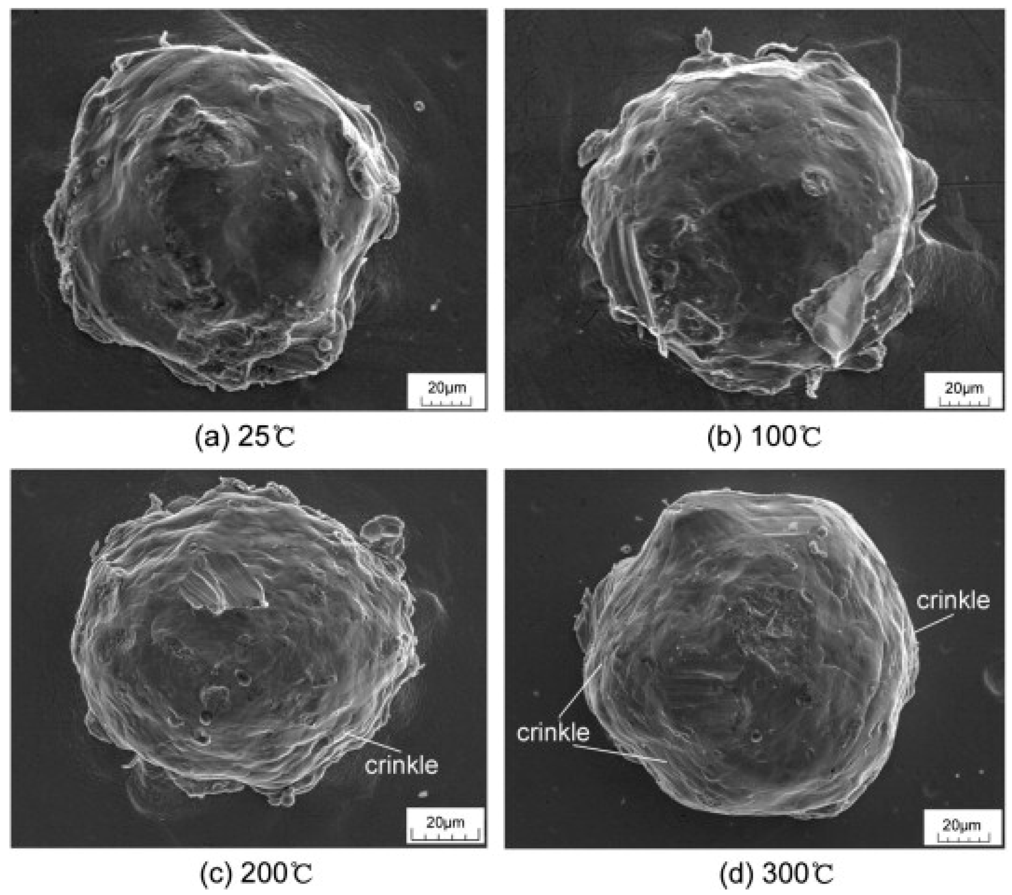
4.2.2. Preheating Temperature

The preheating temperature factor, the characteristics of the particles and substrate, and substrate roughness influence factors affecting the deformation behavior of particles after deposition. Applying an appropriate preheating temperature during the coating process is crucial. Otherwise, it is difficult for the particle velocities to reach a critical value [31]. Studies have indicated [81,82] that increasing the preheating temperature causes thermal softening of the particles, which will intensify the degree of deformation of the particles during the deposition process; thus, the preheating temperature provides a more homogeneous deformation of the particles and the substrate, and the preheating temperature is increased. It is also positively correlated with the particles’ plastic strain, the flattening rate, the depth of the craters, and the jet protrusion morphology; meanwhile, Yin et al. [83] systematically investigated the effect of preheating on the deposition behavior of a single particle, compared with non-preheated particles, preheated particles undergo thermal softening, which leads to more intense plastic deformation, as shown in Figure 26. At higher preheating temperatures, deformed particles with more pronounced metal jets can be observed at the edges of the particles; however, excessively elevated temperature can lead to severe plastic deformation, an increase in the particles’ flattening rate, and even the obscuring of the metal jets.
Yu et al. [62] employed the Euler method to analyze the Cu/Al combination and found that the preheating temperature also affects the residual stress, which decreases as the preheating temperature increases from 100 °C to 300 °C when acting on the particles and the substrate. Therefore, the magnitude of residual stresses varies with different material combinations and changes in preheating temperature. Sun et al. [84] observed the deposition bonding of IN718 particles by controlling the preheating temperature of the IN718 substrate, as shown in Figure 27. They noted that the deformation of the substrate was not obvious when the substrate was not preheated and their obvious cracks and gaps on both sides of the interface. When the preheating temperature was increased to 100 °C, there were still gaps, but the bonding was better than no preheating. When the preheating temperature continued to increase, the jetting phenomenon started to appear, which usually indicates that the substrate and the particles have better bonding strength [85].
The preheating of particles will increase the thermal softening and flattening rate of particles to a certain extent, which is conducive to the bonding of particles with the substrate and, to a certain extent, reduces the critical speed of particles adhering to the substrate. However, the increase in the preheating temperature inevitably will bring some problems; for example, the oxidation of particles or particles in the process of plastic deformation of the impact on the substrate does not occur in the larger work hardening and thus reduces the hardness of the coating. Therefore, we must consider the material’s properties when setting the preheating temperature.

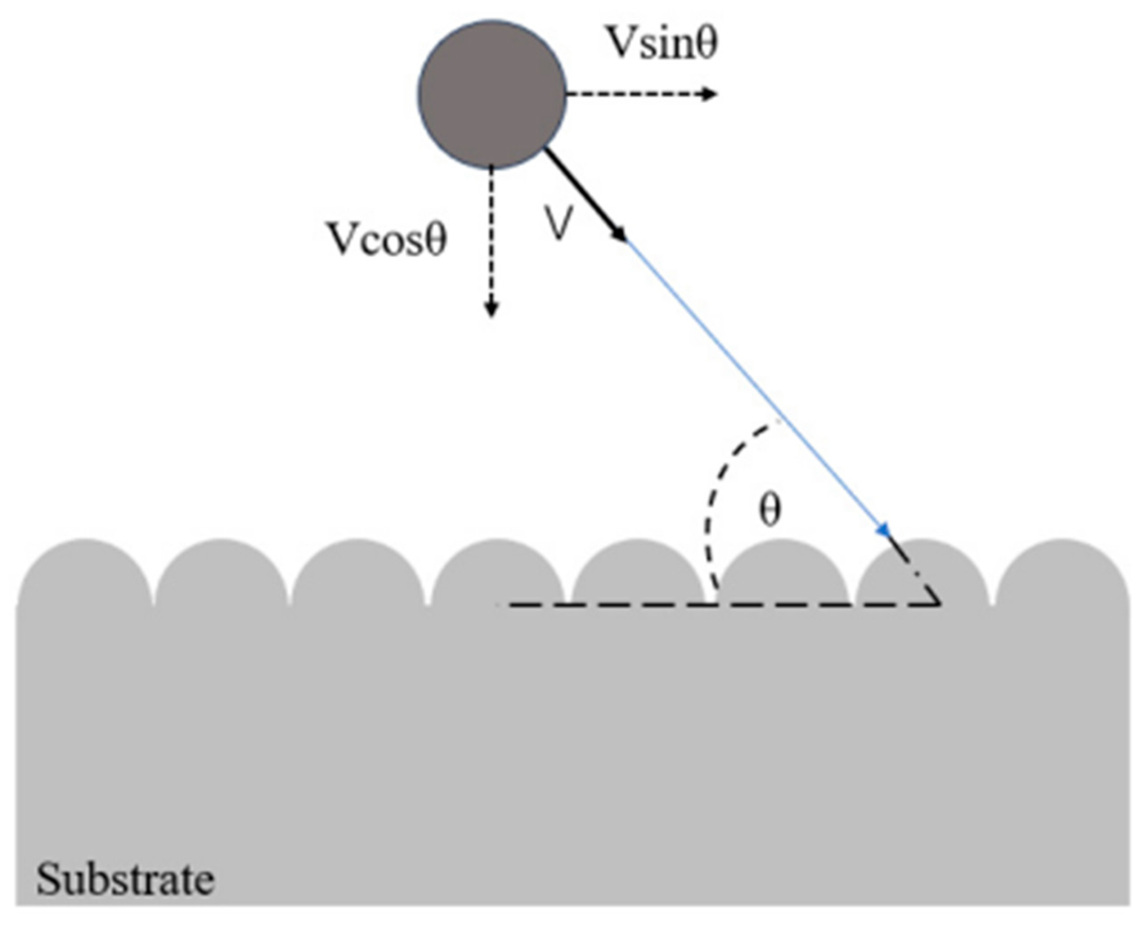
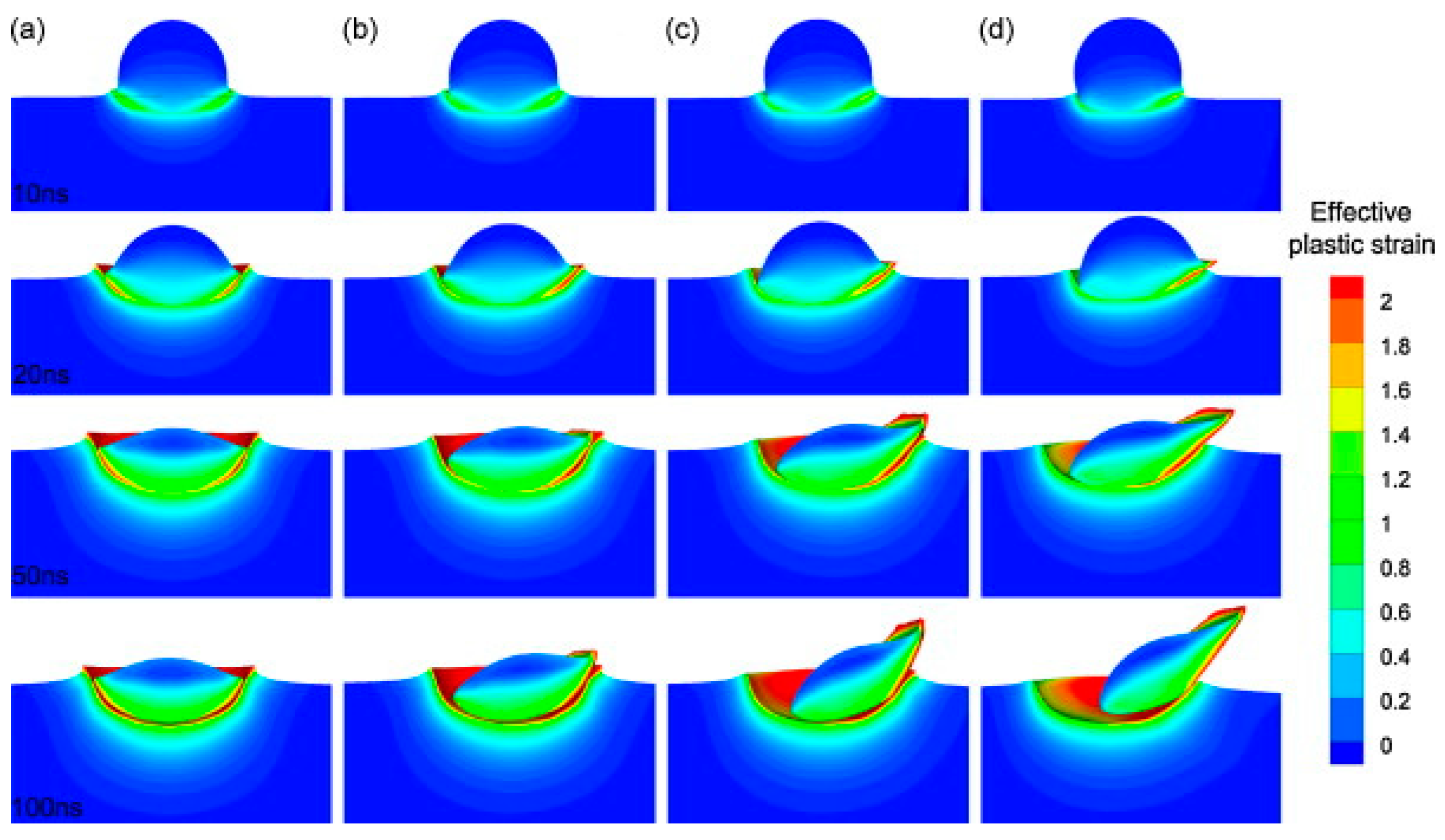
4.2.3. Spraying Angle

Previous studies [86] have shown that the spray angle has a significant effect on the properties of the deposits during CS and may have a greater influence on the deformation behavior of the particles. In conditions where the spray angle is not perpendicular, as shown in Figure 28, the particle velocities can be classified into two directional vectors, horizontal and vertical vectors, respectively. Only the normal velocity component contributes to the deposition of the particles. When the particles hit the base material at an inclined angular velocity, the component velocities are generated in two directions, horizontal and vertical, respectively, and as the spray angle decreases, the normal velocity component decreases, which can significantly deteriorate the deposition quality as well as the bond strength of the prepared coating. As illustrated in Figure 29, as the spray angle decreases for titanium, the porosity of its deposits increases [87]. The microstructure of copper coatings is prepared by different spray angles deposited on polished substrates [88]. The study shows that the particles’ deformation direction varies with the spray angle, and their sliding direction is perpendicular to the direction of the particle approach. Hence, the spray angle significantly affects the particles’ collision behavior.
The Lagrange method [44] was used to simulate the Cu-sprayed Cu particles at different angles, and the results are shown in Figure 30. It found that the different spray angles resulted in the jet only appearing on one side of the particles and the other side of the particles could not adhere to the substrate. This is due to the creation of a very noticeable gap between the particles and the substrate, which contributes to the reduction in the contact area, thus affecting the bonding strength of the coating.
The current simulation work is always carried out in an ideal situation, where the particles are sprayed vertically by default. In contrast, in real situations, it cannot be guaranteed that all particles are sprayed at a vertical angle, which may affect the bonding strength of the particles to the substrate. Therefore, using the Euler method, Binder et al. [87] investigated Ti particles’ particle deformation and coating bonding at different spraying angles. They found that the flattening of particles increased with the incident angle. The adiabatic shear effect was more distinct, and when the particles were sprayed at an angle of 70° or less, the flattened particles tended to bond on one side of the substrate and produced avoids, which is similar to the results of the simulation work by Wen et al. Overall, non-vertical spray angles can be detrimental to the overall deposit performance.

5. Conclusions and Outlook

5.1. Conclusions

This paper reviews the numerical simulation methods in the simulation software ANSYS-Ls-dyna-2022 R1, ABAQUS-6.14, etc., the advantages and disadvantages, as well as the applicability of the modeling methods such as the Lagrange, Euler, and ALE methods, and explores and deepens the understanding of the cold spraying bonding and deposition process. These numerical simulation methods contribute to a vital study of the CS deposition process by investigating phenomena such as stress and strain distributions during the CS deposition process as well as temperature changes at the impact interfaces to predict the critical velocity of the particles and to analyze the residual stresses. However, some limitations remain, such as when the actual particle shape is not an ideal sphere but an irregular powder, the original dislocations and cracks in the substrate or the microcracks are generated during the collision process. Additionally, the phase transition and the surface with different roughness are not fully reflected in these simulation methods, which may impact the accuracy of the simulation results. Combining the advantages and disadvantages of these simulation methods, it is recommended to choose the Lagrange method when interface tracking and time cost reduction are important; if computation accuracy is the priority and computation time is not a concern, it is recommended to choose the Euler method or the CEL method, although they may face the computation termination problem of serious mesh distortion. To avoid computation termination problems, the ALE method or the SPH method are viable alternatives, as both methods avoid the computation termination problem. The methods to avoid the termination of the solution are different. The ALE method is conducted through the adaptive mesh distortion method, which may lead to the inaccuracy of the jet, while the SPH method is not divided into grids to avoid the serious distortion of the mesh to avoid the termination of the calculation problem. If the researcher is interested in exploring the microscopic mechanism of the particle collision after changes, the MD is a better choice.

5.2. Outlook

  • So far, many studies have focused on the ideal cold spray deposition of spherical particles on the surface of a smooth substrate. However, the situation involves irregular particle morphology, varying particle size, and coarse surface substrates. So, the actual simulation of the situation is difficult; although there are studies in this area, the number of studies is still relatively small.
  • Most studies primarily concentrate on simulating the initial layer of particle impact substrate coating. While the initial layer is crucial, successful coating preparation requires equal attention to the same material’s second layer and multi-layer particle combinations. Regrettably, research in this area remains limited.
  • Considerable progress has been made in numerically simulating cold spraying at the macroscopic level. However, there has been little simulation at the microscopic level, particularly in addressing the internal organization of particles/substrate and how it changes after a collision. Furthermore, the impact of particle organization on coating properties after deposition has not been thoroughly investigated.

Author Contributions

Conceptualization, Q.W., Y.C. and Z.L.; methodology, Q.W., Y.C. and Z.L.; software, Q.W. and C.S.R.; validation, Q.W., Z.L., J.L. and H.L.; formal analysis, Q.W. and C.S.R.; investigation, Z.L. and Y.Z.; resources, Z.W.; data curation, Q.W., Y.C. and Z.L.; writing—original draft preparation, Z.L., Y.Z. and C.S.R.; writing—review and editing, C.S.R., Q.W., Y.C. and Z.L.; visualization, Z.L. and Y.Z.; supervision, Q.W. and Y.C.; project administration, Q.W.; funding acquisition, Q.W. All authors have read and agreed to the published version of the manuscript.

Funding

This work was financially supported by the Natural Science Foundation of Hunan Province, China (2023JJ30153).

Institutional Review Board Statement

Not applicable.

Informed Consent Statement

Not applicable.

Data Availability Statement

Not applicable.

Conflicts of Interest

The authors declare no conflicts of interest.

References

  1. Oyinbo, S.T.; Jen, T.-C. Investigation of the process parameters and restitution coefficient of ductile materials during cold gas dynamic spray (CGDS) using finite element analysis. Addit. Manuf. 2020, 31, 100986. [Google Scholar] [CrossRef]
  2. Papyrin, A. Cold Spray Technology. Adv. Mater. Process. 2001, 159, 49. [Google Scholar]
  3. Yin, S.; Cavaliere, P.; Aldwell, B.; Jenkins, R.; Liao, H.; Li, W.; Lupoi, R. Cold spray additive manufacturing and repair: Fundamentals and applications. Addit. Manuf. 2018, 21, 628–650. [Google Scholar] [CrossRef]
  4. Yu, T.; Chen, M.; Wu, Z. Experimental and numerical study of deposition mechanisms for cold spray additive manufacturing process. Chin. J. Aeronaut. 2022, 35, 276–290. [Google Scholar] [CrossRef]
  5. Gärtner, F.; Schmidt, T.; Stoltenhoff, T.; Kreye, H. Recent Developments and Potential Applications of Cold Spraying. Adv. Eng. Mater. 2006, 8, 611–618. [Google Scholar] [CrossRef]
  6. Irissou, E.; Legoux, J.-G.; Ryabinin, A.N.; Jodoin, B.; Moreau, C. Review on Cold Spray Process and Technology: Part I—Intellectual Property. J. Therm. Spray Technol. 2008, 17, 495–516. [Google Scholar] [CrossRef]
  7. Assadi, H.; Kreye, H.; Gärtner, F.; Klassen, T. Cold spraying—A materials perspective. Acta Mater. 2016, 116, 382–407. [Google Scholar] [CrossRef]
  8. Fardan, A.; Berndt, C.C.; Ahmed, R. Numerical modelling of particle impact and residual stresses in cold sprayed coatings: A review. Surf. Coat. Technol. 2021, 409, 126835. [Google Scholar] [CrossRef]
  9. Hassani-Gangaraj, M.; Veysset, D.; Champagne, V.K.; Nelson, K.A.; Schuh, C.A. Adiabatic shear instability is not necessary for adhesion in cold spray. Acta Mater. 2018, 158, 430–439. [Google Scholar] [CrossRef]
  10. Assadi, H.; Gärtner, F.; Stoltenhoff, T.; Kreye, H. Bonding mechanism in cold gas spraying. Acta Mater. 2003, 51, 4379–4394. [Google Scholar] [CrossRef]
  11. Khodabakhshi, F.; Marzbanrad, B.; Jahed, H.; Gerlich, A.P. Interfacial bonding mechanisms between aluminum and titanium during cold gas spraying followed by friction-stir modification. Appl. Surf. Sci. 2018, 462, 739–752. [Google Scholar] [CrossRef]
  12. Wang, Q.; Zhang, M.X. Review on Recent Research and Development of Cold Spray Technologies. Key Eng. Mater. 2013, 533, 1–52. [Google Scholar] [CrossRef]
  13. Yildirim, B.; Fukanuma, H.; Ando, T.; Gouldstone, A.; Müftü, S. A Numerical Investigation Into Cold Spray Bonding Processes. J. Tribol. 2014, 137, 011102. [Google Scholar] [CrossRef]
  14. Li, W.-Y.; Liao, H.; Li, C.-J.; Bang, H.-S.; Coddet, C. Numerical simulation of deformation behavior of Al particles impacting on Al substrate and effect of surface oxide films on interfacial bonding in cold spraying. Appl. Surf. Sci. 2007, 253, 5084–5091. [Google Scholar] [CrossRef]
  15. Wang, F. Deposition characteristic of Al particles on Mg alloy micro-channel substrate by cold spray. Int. J. Adv. Manuf. Technol. 2016, 91, 791–802. [Google Scholar] [CrossRef]
  16. Cloutman, L.D. SPH (Smoothed Particle Hydrodynamics) Simulations of Hypervelocity Impacts; Lawrence Livermore National Lab.: Livermore, CA, USA, 1991. [Google Scholar]
  17. Wang, Q.; Luo, X.; Tsutsumi, S.; Sasaki, T.; Li, C.; Ma, N. Measurement and analysis of cold spray residual stress using arbitrary Lagrangian–Eulerian method. Addit. Manuf. 2020, 35, 101296. [Google Scholar] [CrossRef]
  18. Chen, Q.; Xie, W.; Champagne, V.K.; Nardi, A.; Lee, J.-H.; Müftü, S. On adiabatic shear instability in impacts of micron-scale Al-6061 particles with sapphire and Al-6061 substrates. Int. J. Plast. 2023, 166, 103630. [Google Scholar] [CrossRef]
  19. Li, W.Y.; Yu, M.; Wang, F.F.; Yin, S.; Liao, H.L. A Generalized Critical Velocity Window Based on Material Property for Cold Spraying by Eulerian Method. J. Therm. Spray Technol. 2014, 23, 557–566. [Google Scholar] [CrossRef]
  20. Yu, M.; Li, W.Y.; Wang, F.F.; Liao, H.L. Finite Element Simulation of Impacting Behavior of Particles in Cold Spraying by Eulerian Approach. J. Therm. Spray Technol. 2012, 21, 745–752. [Google Scholar] [CrossRef]
  21. Cavaliere, P.; Silvello, A. Finite element analyses of pure Ni cold spray particles impact related to coating crack behaviour. Surf. Eng. 2018, 34, 361–368. [Google Scholar] [CrossRef]
  22. Zhou, H.; Li, C.; Bennett, C.; Tanvir, H.; Li, C. Numerical Analysis of Deformation Behavior and Interface Bonding of Ti6Al4V Particle After Subsequent Impact During Cold Spraying. J. Therm. Spray Technol. 2021, 30, 1093–1106. [Google Scholar] [CrossRef]
  23. Johnson, G.R.; Cook, W.H. Fracture characteristics of three metals subjected to various strains, strain rates, temperatures and pressures. Eng. Fract. Mech. 1985, 21, 31–48. [Google Scholar] [CrossRef]
  24. Johnson, G.R. A Constitutive Model and Date for Metals Subject to Large Strains, High Strain Rate and High Temperatures. In Proceedings of the 7th International Symposium on Ballistics, The Hague, The Netherlands, 19–21 April 1983. [Google Scholar]
  25. Henao, J.; Bolelli, G.; Concustell, A.; Lusvarghi, L.; Dosta, S.; Cano, I.G.; Guilemany, J.M. Deposition behavior of cold-sprayed metallic glass particles onto different substrates. Surf. Coat. Technol. 2018, 349, 13–23. [Google Scholar] [CrossRef]
  26. Abed, F.H.; Voyiadjis, G.Z. A consistent modified Zerilli-Armstrong flow stress model for BCC and FCC metals for elevated temperatures. Acta Mech. 2005, 175, 1–18. [Google Scholar] [CrossRef]
  27. Cormier, Y.; Dupuis, P.; Jodoin, B.; Ghaei, A. Finite Element Analysis and Failure Mode Characterization of Pyramidal Fin Arrays Produced by Masked Cold Gas Dynamic Spray. J. Therm. Spray Technol. 2015, 24, 1549–1565. [Google Scholar] [CrossRef]
  28. Zhang, B.; Shim, V.P.W. Effect of strain rate on microstructure of polycrystalline oxygen-free high conductivity copper severely deformed at liquid nitrogen temperature. Acta Mater. 2010, 58, 6810–6827. [Google Scholar] [CrossRef]
  29. Chakrabarty, R.; Song, J. A modified Johnson-Cook material model with strain gradient plasticity consideration for numerical simulation of cold spray process. Surf. Coat. Technol. 2020, 397, 125981. [Google Scholar] [CrossRef]
  30. Feng, W.; Ming, Z. Simulation of Particle Deposition Behavior in Cold-Sprayed Mg Anticorrosion Coating. Mater. Manuf. Process. 2015, 31, 1483–1489. [Google Scholar] [CrossRef]
  31. Grujicic, M.; Zhao, C.L.; DeRosset, W.S.; Helfritch, D. Adiabatic shear instability based mechanism for particles/substrate bonding in the cold-gas dynamic-spray process. Mater. Des. 2004, 25, 681–688. [Google Scholar] [CrossRef]
  32. Yin, S.; Wang, X.-F.; Li, W.-Y.; Xu, B.-P. Numerical Investigation on Effects of Interactions Between Particles on Coating Formation in Cold Spraying. J. Therm. Spray Technol. 2009, 18, 686–693. [Google Scholar] [CrossRef]
  33. Li, C.-J.; Li, W.-Y. Deposition characteristics of titanium coating in cold spraying. Surf. Coat. Technol. 2003, 167, 278–283. [Google Scholar] [CrossRef]
  34. King, P.C.; Bae, G.; Zahiri, S.H.; Jahedi, M.; Lee, C. An Experimental and Finite Element Study of Cold Spray Copper Impact onto Two Aluminum Substrates. J. Therm. Spray Technol. 2010, 19, 620–634. [Google Scholar] [CrossRef]
  35. Li, Y.; Wang, X.-F.; Yin, S.; Xu, S.-L. Influence of Particle Initial Temperature on High Velocity Impact Process in Cold Spraying. Procedia Environ. Sci. 2012, 12, 298–304. [Google Scholar] [CrossRef]
  36. Suo, X.K.; Liu, T.K.; Li, W.Y.; Suo, Q.L.; Planche, M.P.; Liao, H.L. Numerical study on the effect of nozzle dimension on particle distribution in cold spraying. Surf. Coat. Technol. 2013, 220, 107–111. [Google Scholar] [CrossRef]
  37. Li, W.-Y.; Zhang, C.; Li, C.-J.; Liao, H. Modeling Aspects of High Velocity Impact of Particles in Cold Spraying by Explicit Finite Element Analysis. J. Therm. Spray Technol. 2009, 18, 921–933. [Google Scholar] [CrossRef]
  38. Yildirim, B.; Muftu, S.; Gouldstone, A. Modeling of high velocity impact of spherical particles. Wear 2011, 270, 703–713. [Google Scholar] [CrossRef]
  39. Wu, Q.; Su, J.; Zhao, W.; Li, J.; Zhang, K.; Wang, L. Determination of Critical Velocity of Cold-Sprayed NiCoCrAlY Coating via Arbitary Lagrangian-Eulerian (ALE) Method of Finite Element Simulation. Coatings 2023, 13, 1992. [Google Scholar] [CrossRef]
  40. Gingold, R.A.; Monaghan, J.J. Smoothed particle hydrodynamics: Theory and application to non-spherical stars. Mon. Not. R. Astron. Soc. 1977, 181, 375–389. [Google Scholar] [CrossRef]
  41. Lucy, L.B. Numerical approach to the testing of the fission hypothesis. Astron. J. 1977, 82, 12. [Google Scholar] [CrossRef]
  42. Saleh, M.; Luzin, V.; Spencer, K. Analysis of the residual stress and bonding mechanism in the cold spray technique using experimental and numerical methods. Surf. Coat. Technol. 2014, 252, 15–28. [Google Scholar] [CrossRef]
  43. Lemiale, V.; King, P.C.; Rudman, M.; Prakash, M.; Cleary, P.W.; Jahedi, M.Z.; Gulizia, S. Temperature and strain rate effects in cold spray investigated by smoothed particle hydrodynamics. Surf. Coat. Technol. 2014, 254, 121–130. [Google Scholar] [CrossRef]
  44. Li, W.-Y.; Yin, S.; Wang, X.-F. Numerical investigations of the effect of oblique impact on particle deformation in cold spraying by the SPH method. Appl. Surf. Sci. 2010, 256, 3725–3734. [Google Scholar] [CrossRef]
  45. Abubakar, A.A. A hybrid computational approach for modeling cold spray deposition. Eng. Sci. Technol. Int. J. 2023, 48, 101579. [Google Scholar] [CrossRef]
  46. Christoulis, D.K.; Jeandin, M.; Irissou, E.; Legoux, J.-G.; Knapp, W. Laser-Assisted Cold Spray (LACS); Dumitras, D.C., Ed.; Nd YAG Laser, InTech: New York, NY, USA, 2012; pp. 59–96. [Google Scholar] [CrossRef]
  47. Gnanasekaran, B.; Liu, G.-R.; Fu, Y.; Wang, G.; Niu, W.; Lin, T. A Smoothed Particle Hydrodynamics (SPH) procedure for simulating cold spray process—A study using particles. Surf. Coat. Technol. 2019, 377, 124812. [Google Scholar] [CrossRef]
  48. Yin, S.; Wang, X.-F.; Xu, B.-P.; Li, W.-Y. Examination on the Calculation Method for Modeling the Multi-Particle Impact Process in Cold Spraying. J. Therm. Spray Technol. 2010, 19, 1032–1041. [Google Scholar] [CrossRef]
  49. Manap, A.; Nooririnah, O.; Misran, H.; Okabe, T.; Ogawa, K. Experimental and SPH study of cold spray impact between similar and dissimilar metals. Surf. Eng. 2014, 30, 335–341. [Google Scholar] [CrossRef]
  50. Schmidt, T.; Gärtner, F.; Assadi, H.; Kreye, H. Development of a generalized parameter window for cold spray deposition. Acta Mater. 2006, 54, 729–742. [Google Scholar] [CrossRef]
  51. Li, W.-Y.; Liao, H.; Li, C.-J.; Li, G.; Coddet, C.; Wang, X. On high velocity impact of micro-sized metallic particles in cold spraying. Appl. Surf. Sci. 2006, 253, 2852–2862. [Google Scholar] [CrossRef]
  52. Wang, F.F.; Li, W.Y.; Yu, M.; Liao, H.L. Prediction of Critical Velocity During Cold Spraying Based on a Coupled Thermomechanical Eulerian Model. J. Therm. Spray Technol. 2014, 23, 60–67. [Google Scholar] [CrossRef]
  53. Yu, M.; Li, W.Y.; Wang, F.F.; Suo, X.K.; Liao, H.L. Effect of particle and substrate preheating on particle deformation behavior in cold spraying. Surf. Coat. Technol. 2013, 220, 174–178. [Google Scholar] [CrossRef]
  54. Schmidt, T.; Assadi, H.; Gärtner, F.; Richter, H.; Stoltenhoff, T.; Kreye, H.; Klassen, T. From Particle Acceleration to Impact and Bonding in Cold Spraying. J. Therm. Spray Technol. 2009, 18, 794–808. [Google Scholar] [CrossRef]
  55. Ardeshiri Lordejani, A.; Colzani, D.; Guagliano, M.; Bagherifard, S. An inclusive numerical framework to assess the role of feedstock features on the quality of cold spray deposits. Mater. Des. 2022, 224, 111374. [Google Scholar] [CrossRef]
  56. Oyinbo, S.T.; Jen, T.-C. Feasibility of numerical simulation methods on the Cold Gas Dynamic Spray (CGDS) Deposition process for ductile materials. Manuf. Rev. 2020, 7, 24. [Google Scholar] [CrossRef]
  57. Heydari Astaraee, A.; Colombo, C.; Bagherifard, S. Numerical Modeling of Bond Formation in Polymer Surface Metallization Using Cold Spray. J. Therm. Spray Technol. 2021, 30, 1765–1776. [Google Scholar] [CrossRef]
  58. Nélias, D.; Xie, J.; Walter-Le Berre, H.; Ichikawa, Y.; Ogawa, K. Simulation of the Cold Spray Deposition Process for Aluminum and Copper using Lagrangian, ALE and CEL Methods. In Thermomechanical Industrial Processes: Modeling and Numerical Simulation; Wiley-Blackwell: Hoboken, NJ, USA, 2014; pp. 321–358. [Google Scholar]
  59. Malama, T.; Hamweendo, A.; Botef, I. Molecular Dynamics Simulation of Ti and Ni Particles on Ti Substrate in the Cold Gas Dynamic Spray (CGDS) Process. Mater. Sci. Forum 2015, 828–829, 453–460. [Google Scholar] [CrossRef]
  60. Joshi, A.; James, S. Molecular dynamics simulation study of cold spray process. J. Manuf. Process. 2018, 33, 136–143. [Google Scholar] [CrossRef]
  61. Sun, C.; Zhou, X.; Xie, C.; Liu, B. Investigating hard/soft combinations of cold spraying by Eulerian approach. Surf. Eng. 2020, 36, 1049–1057. [Google Scholar] [CrossRef]
  62. Li, W.; Yang, K.; Zhang, D.; Zhou, X. Residual Stress Analysis of Cold-Sprayed Copper Coatings by Numerical Simulation. J. Therm. Spray Technol. 2015, 25, 131–142. [Google Scholar] [CrossRef]
  63. Van Steenkiste, T.H.; Smith, J.R.; Teets, R.E. Aluminum coatings via kinetic spray with relatively large powder particles. Surf. Coat. Technol. 2002, 154, 237–252. [Google Scholar] [CrossRef]
  64. Gärtner, F.; Stoltenhoff, T.; Schmidt, T.; Kreye, H. The Cold Spray Process and Its Potential for Industrial Applications. J. Therm. Spray Technol. 2006, 15, 223–232. [Google Scholar] [CrossRef]
  65. Ning, X.-J.; Jang, J.-H.; Kim, H.-J. The effects of powder properties on in-flight particle velocity and deposition process during low pressure cold spray process. Appl. Surf. Sci. 2007, 253, 7449–7455. [Google Scholar] [CrossRef]
  66. Mauer, G.; Singh, R.; Rauwald, K.H.; Schrüfer, S.; Wilson, S.; Vaßen, R. Diagnostics of Cold-Sprayed Particle Velocities Approaching Critical Deposition Conditions. J. Therm. Spray Technol. 2017, 26, 1423–1433. [Google Scholar] [CrossRef]
  67. Yin, S.; Meyer, M.; Li, W.; Liao, H.; Lupoi, R. Gas Flow, Particle Acceleration, and Heat Transfer in Cold Spray: A review. J. Therm. Spray Technol. 2016, 25, 874–896. [Google Scholar] [CrossRef]
  68. Luo, X.-T.; Li, Y.-J.; Li, C.-J. A comparison of cold spray deposition behavior between gas atomized and dendritic porous electrolytic Ni powders under the same spray conditions. Mater. Lett. 2016, 163, 58–60. [Google Scholar] [CrossRef]
  69. MacDonald, D.; Fernández, R.; Delloro, F.; Jodoin, B. Cold Spraying of Armstrong Process Titanium Powder for Additive Manufacturing. J. Therm. Spray Technol. 2017, 26, 598–609. [Google Scholar] [CrossRef]
  70. Munagala, V.N.V.; Akinyi, V.; Vo, P.; Chromik, R.R. Influence of Powder Morphology and Microstructure on the Cold Spray and Mechanical Properties of Ti6Al4V Coatings. J. Therm. Spray Technol. 2018, 27, 827–842. [Google Scholar] [CrossRef]
  71. Qiu, X.; Tariq, N.u.H.; Qi, L.; Tang, J.-R.; Cui, X.-Y.; Du, H.; Wang, J.-Q.; Xiong, T.-Y. Influence of particulate morphology on microstructure and tribological properties of cold sprayed A380/Al2O3 composite coatings. J. Mater. Sci. Technol. 2020, 44, 9–18. [Google Scholar] [CrossRef]
  72. Yin, S.; Wang, X.-F.; Li, W.Y.; Jie, H.-E. Effect of substrate hardness on the deformation behavior of subsequently incident particles in cold spraying. Appl. Surf. Sci. 2011, 257, 7560–7565. [Google Scholar] [CrossRef]
  73. Ziemian, C.W.; Sharma, M.M.; Bouffard, B.D.; Nissley, T.; Eden, T.J. Effect of substrate surface roughening and cold spray coating on the fatigue life of AA2024 specimens. Mater. Des. 2014, 54, 212–221. [Google Scholar] [CrossRef]
  74. Blochet, Q.; Delloro, F.; N’Guyen, F.; Jeulin, D.; Borit, F.; Jeandin, M. Effect of the Cold-Sprayed Aluminum Coating-Substrate Interface Morphology on Bond Strength for Aircraft Repair Application. J. Therm. Spray Technol. 2017, 26, 671–686. [Google Scholar] [CrossRef]
  75. Richer, P.; Jodoin, B.; Ajdelsztajn, L.; Lavernia, E.J. Substrate Roughness and Thickness Effects on Cold Spray Nanocrystalline Al-Mg Coatings. J. Therm. Spray Technol. 2006, 15, 246–254. [Google Scholar] [CrossRef]
  76. Singh, R.; Rauwald, K.H.; Wessel, E.; Mauer, G.; Schruefer, S.; Barth, A.; Wilson, S.; Vassen, R. Effects of substrate roughness and spray-angle on deposition behavior of cold-sprayed Inconel 718. Surf. Coat. Technol. 2017, 319, 249–259. [Google Scholar] [CrossRef]
  77. Kumar, S.; Bae, G.; Lee, C. Influence of substrate roughness on bonding mechanism in cold spray. Surf. Coat. Technol. 2016, 304, 592–605. [Google Scholar] [CrossRef]
  78. Jiang, S.; Zhou, H.; Li, X.; Wang, Y. Numerical simulation of substrate roughness on the interface bonding of cold-sprayed Ti6Al4V. China Surface Engineering 2022, 35, 262–272. (In Chinese) [Google Scholar]
  79. Zhou, X.; Su, X.; Cui, H.; Guo, H.; Wu, X.; Zhang, J. Effect of material properties of cold-sprayed particles on its impacting behavior. Acta Metallurgica Sinica 2008, 44, 1286–1291. (In Chinese) [Google Scholar]
  80. Meng, F.; Yue, S.; Song, J. Quantitative prediction of critical velocity and deposition efficiency in cold-spray: A finite-element study. Scr. Mater. 2015, 107, 83–87. [Google Scholar] [CrossRef]
  81. Li, W.Y.; Yang, K.; Yin, S.; Guo, X.P. Numerical Analysis of Cold Spray Particles Impacting Behavior by the Eulerian Method: A Review. J. Therm. Spray Technol. 2016, 25, 1441–1460. [Google Scholar] [CrossRef]
  82. Li, W.Y.; Zhang, D.D.; Huang, C.J.; Yin, S.; Yu, M.; Wang, F.F.; Liao, H.L. Modelling of impact behaviour of cold spray particles: Review. Surf. Eng. 2014, 30, 299–308. [Google Scholar] [CrossRef]
  83. Yin, S.; Wang, X.; Suo, X.; Liao, H.; Guo, Z.; Li, W.; Coddet, C. Deposition behavior of thermally softened copper particles in cold spraying. Acta Mater. 2013, 61, 5105–5118. [Google Scholar] [CrossRef]
  84. Sun, W.; Tan, A.W.Y.; Bhowmik, A.; Marinescu, I.; Song, X.; Zhai, W.; Li, F.; Liu, E. Deposition characteristics of cold sprayed Inconel 718 particles on Inconel 718 substrates with different surface conditions. Mater. Sci. Eng. A 2018, 720, 75–84. [Google Scholar] [CrossRef]
  85. Yin, S.; Suo, X.; Xie, Y.; Li, W.; Lupoi, R.; Liao, H. Effect of substrate temperature on interfacial bonding for cold spray of Ni onto Cu. J. Mater. Sci. 2015, 50, 7448–7457. [Google Scholar] [CrossRef]
  86. Seng, D.H.L.; Zhang, Z.; Zhang, Z.-Q.; Meng, T.L.; Teo, S.L.; Tan, B.H.; Loi, Q.; Pan, J. Influence of spray angle in cold spray deposition of Ti-6Al-4V coatings on Al6061-T6 substrates. Surf. Coat. Technol. 2022, 432, 128068. [Google Scholar] [CrossRef]
  87. Binder, K.; Gottschalk, J.; Kollenda, M.; Gärtner, F.; Klassen, T. Influence of Impact Angle and Gas Temperature on Mechanical Properties of Titanium Cold Spray Deposits. J. Therm. Spray Technol. 2011, 20, 234–242. [Google Scholar] [CrossRef]
  88. Li, C.J.; Li, W.Y.; Wang, Y.Y.; Fukanuma, H. Effect of Spray Angle on Deposition Characteristics in Cold Spraying. In Proceedings of the ITSC2003, Orlando, FL, USA, 5–8 May 2003; pp. 91–96. [Google Scholar]
Figure 1. Principle of cold spraying equipment (a) high-pressure; (b) low-pressure [3].
Coatings 14 00913 g001
Figure 2. Two mechanisms of jet formation: (a) adiabatic shear instability [8]; (b) hydrodynamic plasticity in which TS is thermally softened; SRH, strain rate hardening; Ve, critical velocity; Vs, impact velocity [9].
Coatings 14 00913 g002
Figure 3. Simulation flow chart of cold spraying particle deposition.
Coatings 14 00913 g003
Figure 4. (a) Two-dimensional model [17]; (b) three-dimensional model [18]. * meaning several times the diameter of the particles.
Coatings 14 00913 g004
Figure 5. Contours of the effective plastic strain of five copper particles impacting on a copper substrate [32] and typical microstructures of the titanium coatings deposited [33]: (a) with the initial distance of 1 μm and (b) with the initial distance of 10 μm, (c) polygon titanium powder and (d) spherical titanium powder.
Coatings 14 00913 g005
Figure 6. Typical numerical simulation method of cold spraying.
Coatings 14 00913 g006
Figure 7. Deformation evolution diagram of a single aluminum particle colliding with an aluminum matrix at a particle temperature of 400 °C and velocity of 500 m/s, (a) von Mises stress at 15 ns; (b) von Mises stress at 30 ns; (c) von Mises stress at 45 ns; (d) PEEQ at 15 ns; (e) PEEQ at 30 ns; (f) PEEQ at 45 ns; (g) Temperature at 15 ns; (h) Temperature at 30 ns; (i) Temperature at 45 ns; and SEM images of CSAM-produced Al6061 samples: (j) low magnification; (k) high magnification [4].
Coatings 14 00913 g007
Figure 8. Distribution of residual stress σX in multilayer CS particles deposited on the substrate at an impact speed of 500 m/s: (a) single particle; (b) one layer of particles; (c) 2 layers of particles; (d) three layers of particles; (e) four layers of particles; (f) comparison among Line 1, Line 2, Line 3, and Line 4. (Note: the positions indicated by P1, P2, P3, and P4 in Figure 7f can be seen from Figure 7b–d,f) [17].
Coatings 14 00913 g008
Figure 9. Comparison of the experimental results and simulation results of Cu spraying Al by ALE method at 550 m/s [15].
Coatings 14 00913 g009
Figure 10. (a) A top view of the experimental results of Cu spraying on a smooth Cu substrate; (b) a cross-sectional view of Cu sprayed on a smooth Cu substrate; (c) Lagrange simulation result diagram; (d) SPH method simulation result chart [44].
Coatings 14 00913 g010
Figure 11. Four-layer simulations showing splat morphology and (a) plastic strain, (b) temperature, and (c) von Mises stress for multiple particles impacting with random velocities and impact points. (d) Splat morphologies obtained from previous experiments [45].
Coatings 14 00913 g011
Figure 12. Cu ball impacting 20 steel by Euler method and comparison with experimental results with different velocities: (a) 350 m/s, (b) 600 m/s, (c) 750 m/s, (d) 1000 m/s, and (e) 1450 m/s [51].
Coatings 14 00913 g012
Figure 13. A PEEQ diagram of simulated Cu/Cu, in which the velocities of Cu are (a) 250 m/s; (b) 290 m/s; (c) 300 m/s; (d) 320 m/s; (e) 350 m/s; (f) 400 m/s; (g) 500 m/s; (h) 600 m/s; (i) 700 m/s [52].
Coatings 14 00913 g013
Figure 14. Influence of impact velocity on stable maximum PEEQ under adiabatic and non-adiabatic conditions [52].
Coatings 14 00913 g014
Figure 15. The Euler method is used to simulate the effective plastic strain isoline of multi-particle impacting the substrate at (a) 140 ns and (b) 190 ns [48]. Typical microstructure of cold sprayed copper coating with (c) low magnification and (d) high magnification [54].
Coatings 14 00913 g015
Figure 16. Influencing factors of cold spraying particle deposition combination and deformation.
Coatings 14 00913 g016
Figure 17. A 25 μm summary of critical velocity of different material particles [50].
Coatings 14 00913 g017
Figure 18. PEEQ diagram of powder with different shapes: (a) spherical powder; (b) coral powder [69].
Coatings 14 00913 g018
Figure 19. Cu’s multi-particle simulated effective plastic strain diagram of Al, Ni, and SS substrates impacted by Cu at 600 m/s and 900 m/s, respectively [72].
Coatings 14 00913 g019
Figure 20. Cross-sectional optical image of aluminum sprayed on AA2024-T3 after chemical etching: (a) as it is; (b) fine sandblasting; (c) medium sandblasting; (d) coarse sandblasting [74].
Coatings 14 00913 g020
Figure 21. Two-dimensional simulation of aluminum particles (Dp = 35 m) from the beginning to the end of impact to AA2024-T3 substrate (a) without surface treatment; (b) fine sandblasting; (c) medium sandblasting; (d) after coarse sand blasting, t0 = 0 ns, t1 = 50 ns, t2 = 100 ns, t3 = 150 ns, and t4 = 200 ns [74].
Coatings 14 00913 g021
Figure 22. Sand grains of (a) F-36 are treated by sandblasting; (b) three-dimensional morphology of IN718 substrate prepared by F-150 sand particles [76].
Coatings 14 00913 g022
Figure 23. SEM and corresponding EBSD micrographs of the interaction between a single particle and the IN718 substrate (a) are well polished, and white arrows indicate spattered materials; (b) F150 sandblasting; (c) sand blasting with F-36 grit [76].
Coatings 14 00913 g023
Figure 24. (I) (a) Bonding strength and (b) microscopic image of Al sprayed steel with different surface roughness; (II) (a) bonding strength and (b) microscopic images of Ti6Al4V with different surface roughness sprayed by Ti [77].
Coatings 14 00913 g024
Figure 25. Effective plastic distribution on the maximum contact area during impact (a) Lagrange method; (b) ALE method [15].
Coatings 14 00913 g025
Figure 26. SEM surface topography of single particle after spraying. The preheating temperatures are as follows: (a) 25 °C; (b) 100 °C; (c) 200 °C; (d) 300 °C [83].
Coatings 14 00913 g026
Figure 27. SEM cross-section views of cold sprayed IN718 single splats deposited on IN718 substrates with temperatures of (a) 25 °C; (b) 100 °C; (c) 200 °C; and (d) 450 °C [84].
Coatings 14 00913 g027
Figure 28. Velocity analysis diagram of particles impacting the substrate.
Coatings 14 00913 g028
Figure 29. Spray angle at (a) 90, (b) 75°, and (c) cross-sectional images of titanium deposits generated at a 45-degree injection angle [87].
Coatings 14 00913 g029
Figure 30. Simulation results of different incident angles (a) 90 spraying angle; (b) spraying angle of 80°; (c) spraying angle of 70°; (d) spraying angle of 60° degrees [44].
Coatings 14 00913 g030
Table 1. Common material parameters.
Material PropertyCuAlFeNiTiTi6Al4VMg Alloy
Density (kg/m3)8930270078708890451044281780
Young’s modulus (GPa)1106820020511611045
Poisson’s ratio0.350.330.330.310.340.360.35
Specific heat (J/(kg k))385900444460528560250
Heat conduction (W/mK)38521076.261601396
Johnson–Cook model parameter
A (MPa)1502651751638071098170
B (MPa)3054263886484821092235
C0.0340.0150.060.0060.01940.0140.013
n0.0960.340.320.330.3190.930.15
m1.0910.551.440.6551.11
Tm (K)13569331809172319231356903
Table 2. Modeling method of cold spraying model.
Numerical Simulation MethodsAdvantageDisadvantageCharacteristicReferences
Lagrange methodThe operation is simple, and the contact interface can be tracked for easy analysis.When the mesh deformation is large, the program is easy to terminate, and the particles are prone to rebound.The delineated mesh moves with the material’s deformation. When the deformation is small, the calculation time is short, and the accuracy is high, which is used for solid analysis.[4,31,34]
Euler methodLarge deformations can be simulated without mesh limitations and with high computational accuracy.Calculations are slow; particle/particle and particle/substrate interfaces cannot be traced.The material can flow freely within the set mesh used for fluid analysis.[20,61,62]
CEL method (coupled Lagrange–Euler method)Ability to simulate extreme deformation of particles and track interfaces with high computational accuracy.Calculations are terminated due to distortion of the substrate mesh, the results of particles and substrate cannot be monitored simultaneously, and the calculations are slower.Combines both Lagrange and Euler features[58]
ALE method (arbitrary Lagrange–Euler method)It can effectively solve the problem of computation termination due to mesh distortion in Lagrange, and the computation speed is fast.Low computational accuracy, failure to solve the problem of particle rebound in the Lagrange, cumbersome parameterization, and unrealistic jet bands generated by particles impacting the substrateAdaptive changes when the mesh is distorted[14,15,17,39]
SPH method (Smooth Particle Hydrodynamics)Extreme deformations can be simulated without mesh limitation, and the calculation accuracy is high when the deformation is large.Uneven particle mass leads to unstable stretching between particles, slower calculation speed, and low calculation accuracy when the deformation amount is small.Modeling material characteristics with a series of particle combinations[42,43,44]
MD method (molecular dynamics method)can simulate the microscopic mechanisms of particles upon impact with the substrate.It is not easy to simulate large-scale particles.Simulates interactions between atoms or molecules; the smaller the particle size, the higher the accuracy.[59,60]
Disclaimer/Publisher’s Note: The statements, opinions and data contained in all publications are solely those of the individual author(s) and contributor(s) and not of MDPI and/or the editor(s). MDPI and/or the editor(s) disclaim responsibility for any injury to people or property resulting from any ideas, methods, instructions or products referred to in the content.

