Article

Tribological Properties of CrN/DLC and CrN Coatings under Different Testing Conditions

1
School of Mechanical and Automotive Engineering, Qingdao University of Technology, Qingdao 266520, China
2
Qingdao Choho Chain Transmission Co., Ltd., Qingdao 266700, China
3
School of Mechanical Engineering, Ningxia University, Yinchuan 750021, China
*
Author to whom correspondence should be addressed.
Coatings 2024, 14(8), 1002; https://doi.org/10.3390/coatings14081002
Submission received: 1 July 2024 / Revised: 1 August 2024 / Accepted: 5 August 2024 / Published: 7 August 2024
(This article belongs to the Section Corrosion, Wear and Erosion)

Abstract

:
CrN and diamond-like carbon (DLC) coatings are deposited on the surface of 431 stainless steel by the direct current magnetron sputtering technique. The surface morphology, micro-structure, hardness, friction, and wear properties of CrN, CrN/DLC and multi-layer composite DLC coatings are investigated by scanning electron microscopy, X-ray diffraction, Raman spectroscopy, X-ray photoelectron spectroscopy, nanoindentation tester, scratch tester, and friction and wear tester. The results show that the surface of the single CrN coating is very rough for the columnar crystal structure with preferred orientation. When it serves as inner transition layers to form the composite DLC coatings, the surface gets much smoother, with reduced defects. The friction and wear results indicate that the composite DLC coatings exhibit lower coefficients of friction, and better wear and corrosion resistance in dry friction, deionized water, and seawater. In the dry wear and friction process, the single CrN coating is easily worn out, and severe friction oxidation and furrow wear both appear with a friction coefficient of 0.48. But the friction coefficient of a CrN coating in seawater is reduced to 0.16, and friction oxidation and wear loss are further reduced with water lubrication. The CrN/DLC coating has excellent tribological performance in three test concoctions and has the lowest friction coefficient of 0.08 in seawater, which is related to the higher sp3 bond content, density (1.907 g/cm3) and high degree of amorphization, contributing to high hardness and a self-lubrication effect. However, due to the limited thickness of CrN/DLC (1.14 µm), it easily peels off and fails during friction and wear in different testing conditions. In multi-layer composite DLC coatings, there are more sp2 bonds with decreased amorphization, high enough thickness (4.02 µm), and increased bonding strength for the formation of different carbides and nitrides of chromium as transition layers, which gives rise to the further decreased average friction coefficient and the lowest wear loss. Therefore, the CrN coating alone has good wear resistance, and, as with the inner transition layer with a DLC coating, it can effectively improve the overall thickness and the bonding strength of the multi-layer films by optimizing the chemical compounds of DLC coatings. These results provide experimental support and reference for the design and selection of surface coatings for 431 stainless steels in different working conditions.

1. Introduction

431 stainless steel, known for its high hardness, strength, and excellent corrosion resistance, is widely used in manufacturing shafts, pumps, valves, bolts, nuts, and washers [1]. The machinery manufacturing industry progresses towards greater speed and precision and higher performance to meet demands for applications under extreme conditions and environments [2]. Marine corrosion is mainly the deterioration or damage caused by the interaction of materials with the seawater and salt. Surface engineering is the practical technology of a surface–substrate system to achieve better service performance that cannot be achieved in the substrate or surface alone. The physical vapor deposition (PVD) method is one of the most common and practical approaches to prepare various coatings at low temperature to achieve the desired properties [3,4,5].
Metal nitride coatings like TiN and CrN, recognized for their high hardness and oxidation resistance, can be very useful in improving the corrosion resistance properties of the substrate due to their performance [6,7]. Additionally, some nitride coatings may form a passivation film in corrosive media, thereby enhancing the material’s wear and corrosion resistance and extending the service life of equipment [3,6]. Among them, CrN coatings, with certain hardness, toughness, and oxidation resistance, are widely used in offshore equipment, cutting tools, and medical instruments [4,8]. However, CrN coatings have a hardness of about 1800–2000 HV and grow in columnar crystals, which results in a rough and porous surface. In corrosive environments, the medium can penetrate through the boundaries of the columnar crystals to the substrate surface; thus, the corrosion resistance of CrN coatings is limited [3]. Though single-layer CrN film or multi-layer CrN film may be prone to form a dense passivation film in the corrosion process, delaying pitting corrosion, their porous surfaces also lead to a higher friction coefficient [9]; hence, the wear resistance of CrN coatings needs further improvement.
In recent years, diamond-like carbon (DLC) films have been found to exhibit excellent properties such as low friction coefficient, high hardness (1900~2200 HV), low thermal expansion coefficient, and good corrosion resistance [10,11]. DLC coatings consist of a three-dimensional amorphous carbon network made up of sp2 and sp3 hybridized carbon atoms. However, due to the large internal stress, DLC coatings have low film–substrate bonding strength, and the large internal stress also limits the overall thickness of the DLC coatings [12,13]. It is known that the structure of the material determines its performance, and the mechanical and tribological properties of DLC coatings also depend on the microstructure, i.e., the ratio of sp2 to sp3 bonded carbon atoms [14,15,16]. Studies have shown that the design of inner transition layers is an effective way to improve their bonding strength and enhance the performance of DLC coatings [17,18]. DLC composited coatings with CrN film as a transition layer exhibit excellent comprehensive performance [19]. It has been found that the microhardness of CrN and DLC composited films can reach 2200~2600 HV. The composited structure can not only increase the thickness of the coating but also enhances its hardness [11,20]. When CrN is used as a transition layer, Cr is often used as the base layer. Since Cr and CrN have the same crystal structure, the interface mismatch is significantly reduced [21,22]. Moreover, a coherent twin boundary forms easily between Cr and CrN interfaces, which will further reduce interfacial stress [4,21], enhance interfacial bonding strength, and improve the performance of composite coatings. Recent studies have found that designing nitride gradient structures or doping the nitride layer with elements like Al and Si can effectively prevent the coarsening of CrN columnar crystals and deduce a denser microstructure, thereby improving the surface quality and corrosion resistance of the DLC coatings [1,23]. The latest interface structure analysis has shown that an amorphous transition layer interface may form between the outer DLC layer and the inner CrN interface. Thus, the combination of CrN and DLC coatings can create a transition interface with a certain element diffusion, which can improve the deformation process and friction wear performance of the composite coatings [17,19].
Based on the above, this paper employs DC magnetron sputtering technology to deposit single-layer CrN, duplex CrN/DLC, and multi-layer composite CrN/CrNC/CrC/DLC coatings on a 431 stainless steel substrate. The friction and wear performance of these coatings in dry atmosphere, deionized water, and seawater environments is studied, and the erosive wear failure mechanisms are analyzed to provide a theoretical basis and technical guidance for a coating design of 431 stainless steels in different conditions.

2. Experiment Details

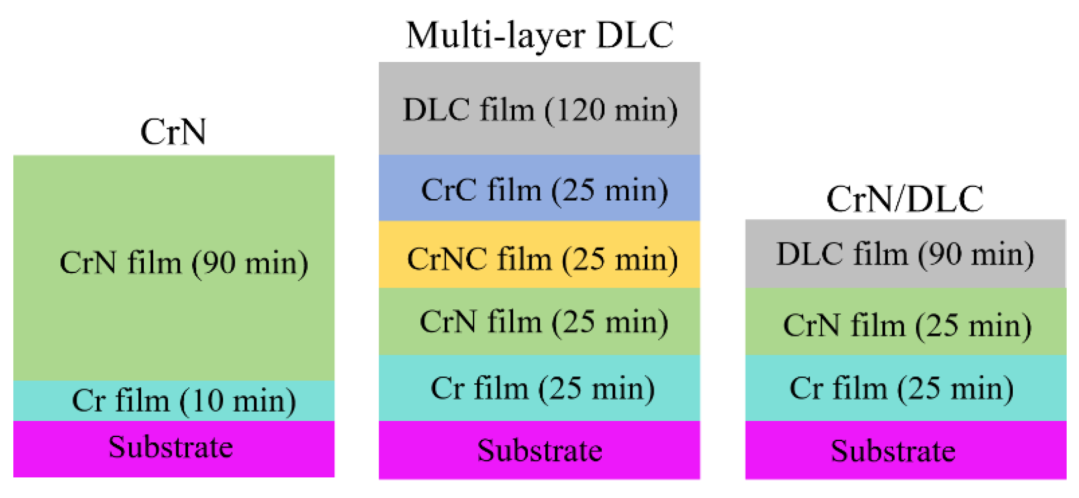
2.1. Preparation of Coatings

CrN, CrN/DLC and CrN/CrNC/CrC/DLC coatings are prepared on the substrate of 431 stainless steel by the DC magnetron sputtering process (Liaoning Beiyu Vauum Technology CO., Ltd., DG-4-BY, Shenyang, China). Before the coating deposition, 431 stainless steel is polished with different sandpapers, then cleaned and blown dry with anhydrous ethanol. Then the substrate is cleaned in the deionized water and anhydrous ethanol for 20 min and dried with nitrogen. Graphite and Cr with a purity of 99.99 wt. % are used as solid targets, and argon and nitrogen gas with a purity of 99.99 wt. % are used as protecting and working gas. During the deposition process, the ionization vacuum is maintained at approximately 0.5 Pa and the temperature is kept at 100 °C. Before deposition, the vacuum is drawn to 3 × 10⁻³ Pa, and a 15-min glow of pure argon gas as cleaning process is carried out at a bias voltage of −200 V.
The detailed process of coating preparation is listed in Table 1. The first layer of all the coatings is a metal Cr layer, which is in direct contact with the substrate, and the target current of Cr is 3 A. During the preparation of CrN coatings, the current of the target Cr is 4 A, and N2 is injected at the same time, and the flow rate is 15 sccm. After CrN preparation, the graphite target with the current of 4 A is used to prepare the outer layer DLC to form the duplex CrN/DLC coatings. In the preparation of a multi-layer composited CrN/CrNC/CrC/DLC coating, after the deposition of CrN layer, N2 injection continues, and the graphite target is opened at the same time, and the deposition time is held for 25 min to form the CrNC layer. Subsequently, N2 injection is turned off but metal Cr and graphite targets continue to be on for 25 min to form the CrC layer. Finally, the metal Cr target is turned off and the deposition continues for 2 h to form the outermost layer of the DLC coating. The temperature during deposition is held at 100 °C and the bias voltage is kept at −200 V with continuous high purity argon input (50 sccm). All coatings are cooled to room temperature in the vacuum chamber before carrying out deposition.
Table 1 presents the detailed deposition parameters, and Figure 1 shows the structural sketches of these three different coatings.

2.2. Characterization and Analysis Methods

The structure of different coatings is characterized using a high-resolution dispersive Raman spectrometer (Thermo Fischer DXR, Waltham, MA, USA) operating at a wavelength of 532 nm, with a spectral measurement range spanning from 800 to 1800 cm−1. The surface morphology, microstructure, and cross-section of the coatings are examined using field emission scanning electron microscopy, SEM (MERLIN Compact, Hamburg, Germany), with an energy-dispersive spectrometer, EDS (UltraDry, Hilden, Germany), at an operating voltage of 15 keV. The phase composition of CrN, CrN/DLC and multi-layer DLC coatings are analyzed by X-ray diffraction, XRD (D8 Advance, Ettlingen, Germany). Samples of single CrN, duplex CrN/DLC, and multi-layer DLC coatings are cut into 10 mm × 10 mm × 3 mm before XRD analysis. The Cu Ka source with a wavelength of 0.154 nm and the continuous surface scanning mode are used, with a scanning speed of 5°/min and scanning range of 20°~90°. In the XRD test, the voltage is 40 kV and the current is 40 mA. XRD data are analyzed by jade6 software and compared with a PDF standard card to distinguish phases. The bonding state and chemical composition of DLC coatings are analyzed by X-ray photoelectron spectroscopy, XPS (Thermo Fischer, ESCALAB 250, Waltham, MA, USA). The hardness and elastic modulus of different coatings are measured using a nanoindenter instrument (Bruker Hysitron TI980, Ettlingen, Germany). five points are randomly pressed on the surface of the multi-layer DLC coatings. The penetration depth of the test indenter is set to approximately 300 nm, which is not to exceed 1/10 of the total coating thickness to avoid the influence of substrate. The average value of these five points is taken to investigate the experimental value of nanohardness and elastic modulus. In the scratch test (UNHT, Geneva, Switzerland), a continuous load with the speed of 5 N/min is carried out. The tribological properties of coatings are evaluated at room temperature using a reciprocating friction and wear tester (Bruker UMT-3, Billerica, MA, USA). The counter-grinding balls are made of GCr15 steel with a diameter of 9 mm. During the testing, a stable load of 5N is applied at a stable frequency of 2 Hz for 30 min. The wear track of coatings is analyzed by SEM (MERLIN Compact, Hamburg, Germany) and the elements analysis is carried out by EDS (UltraDry, Hilden, Germany).

3. Results and Discussion

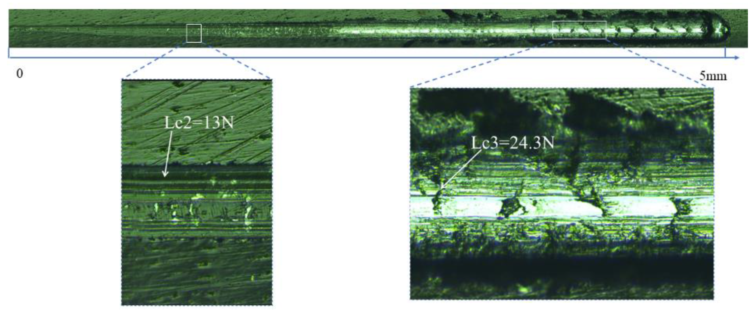
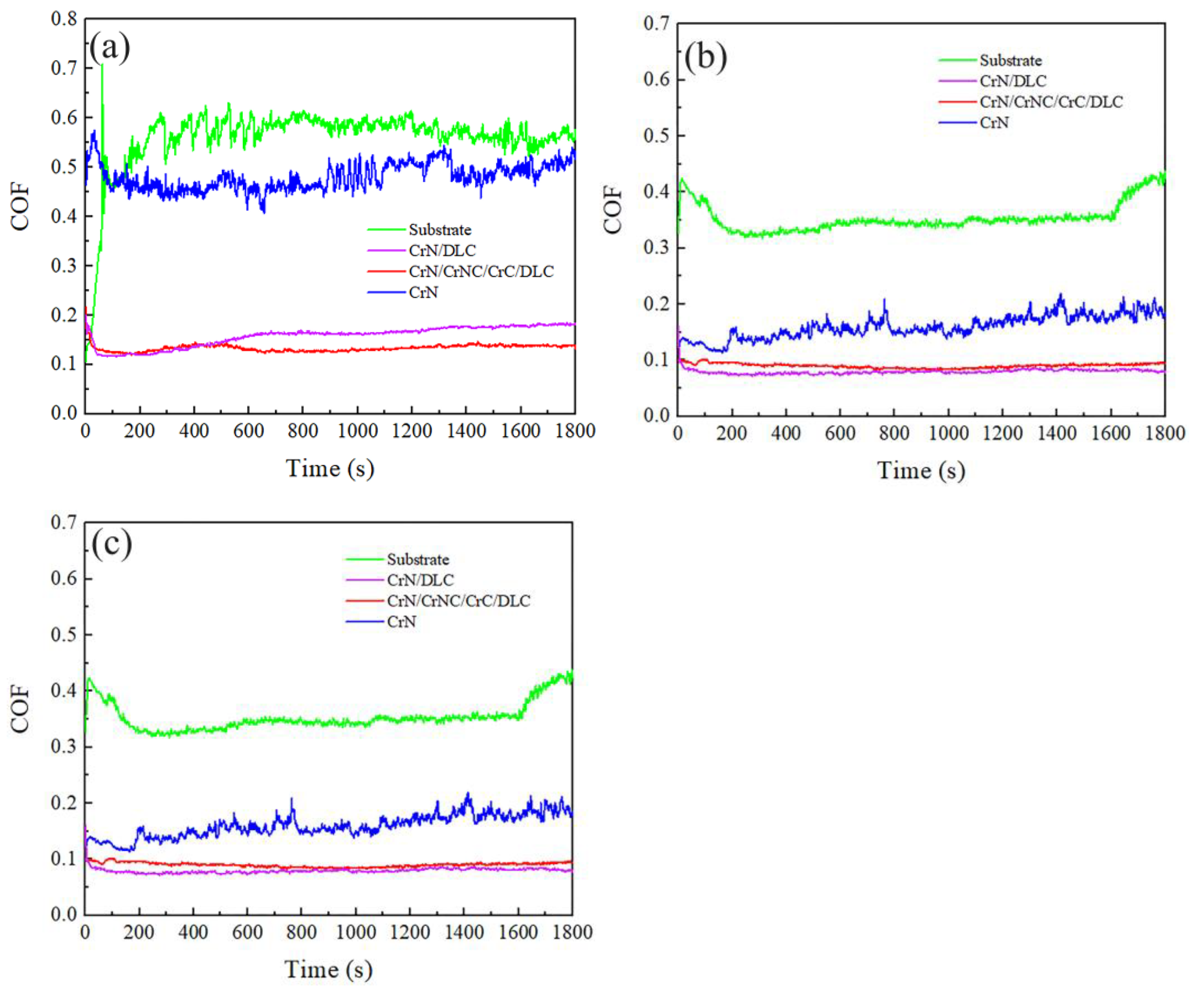
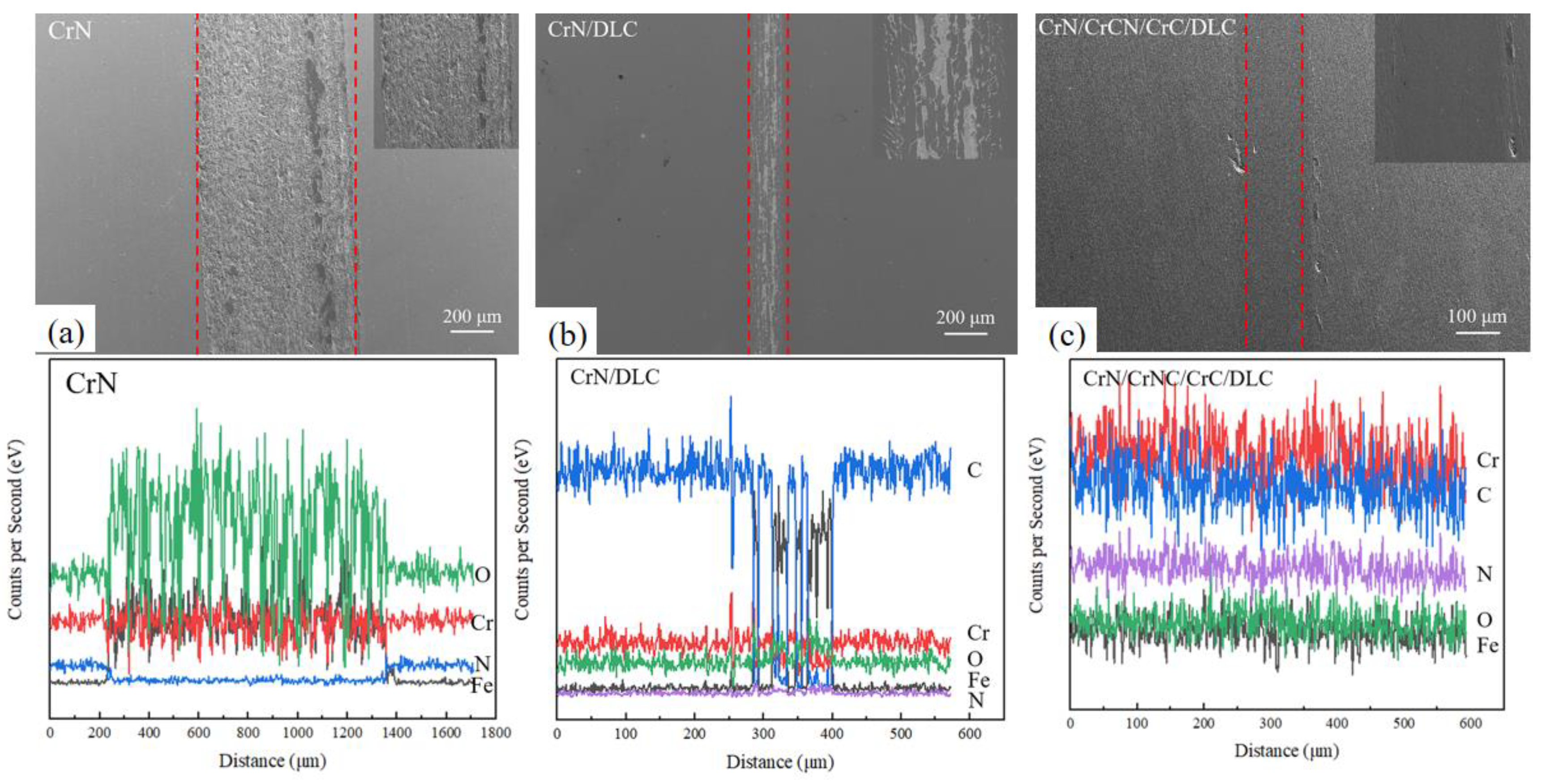
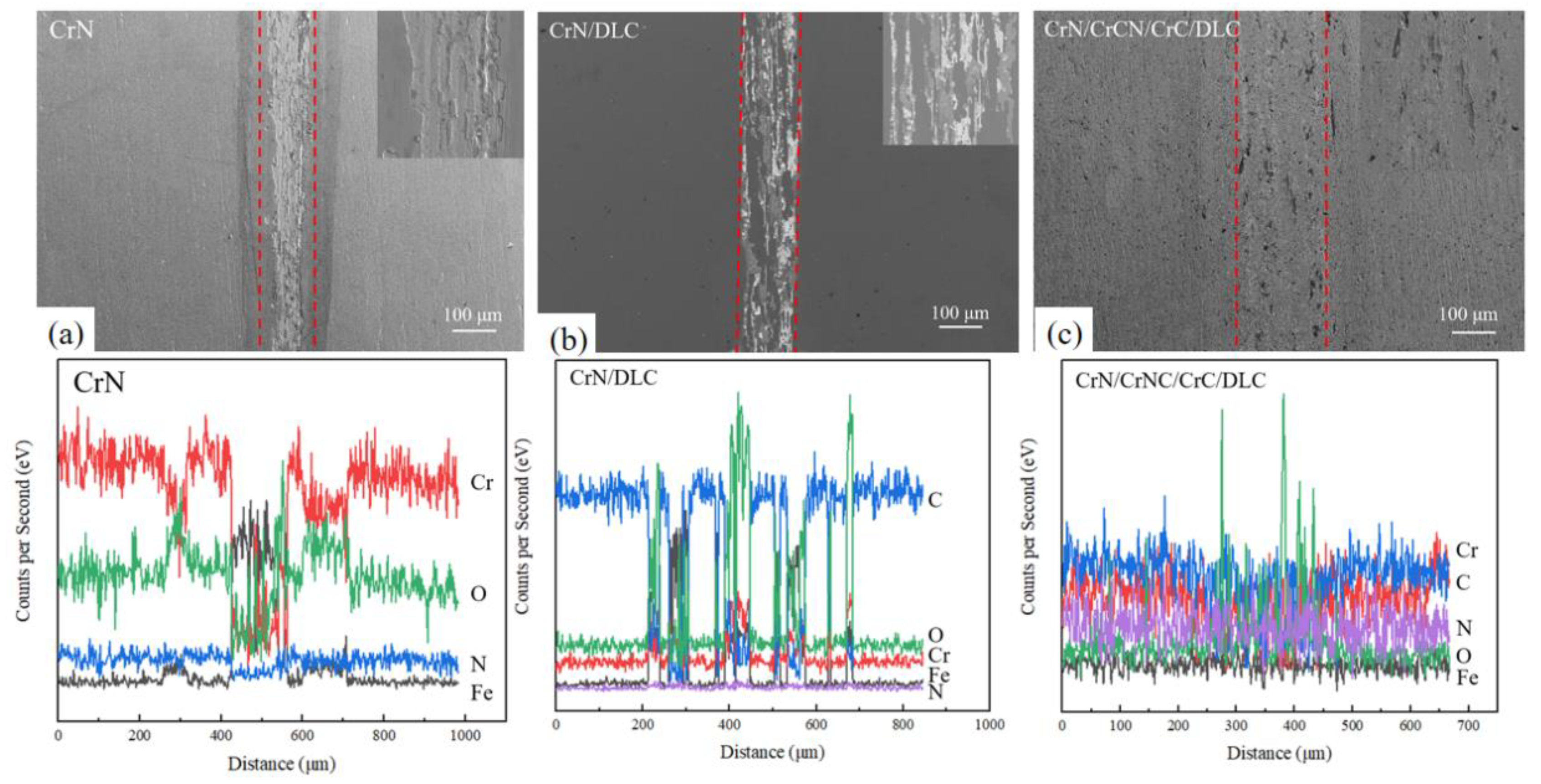
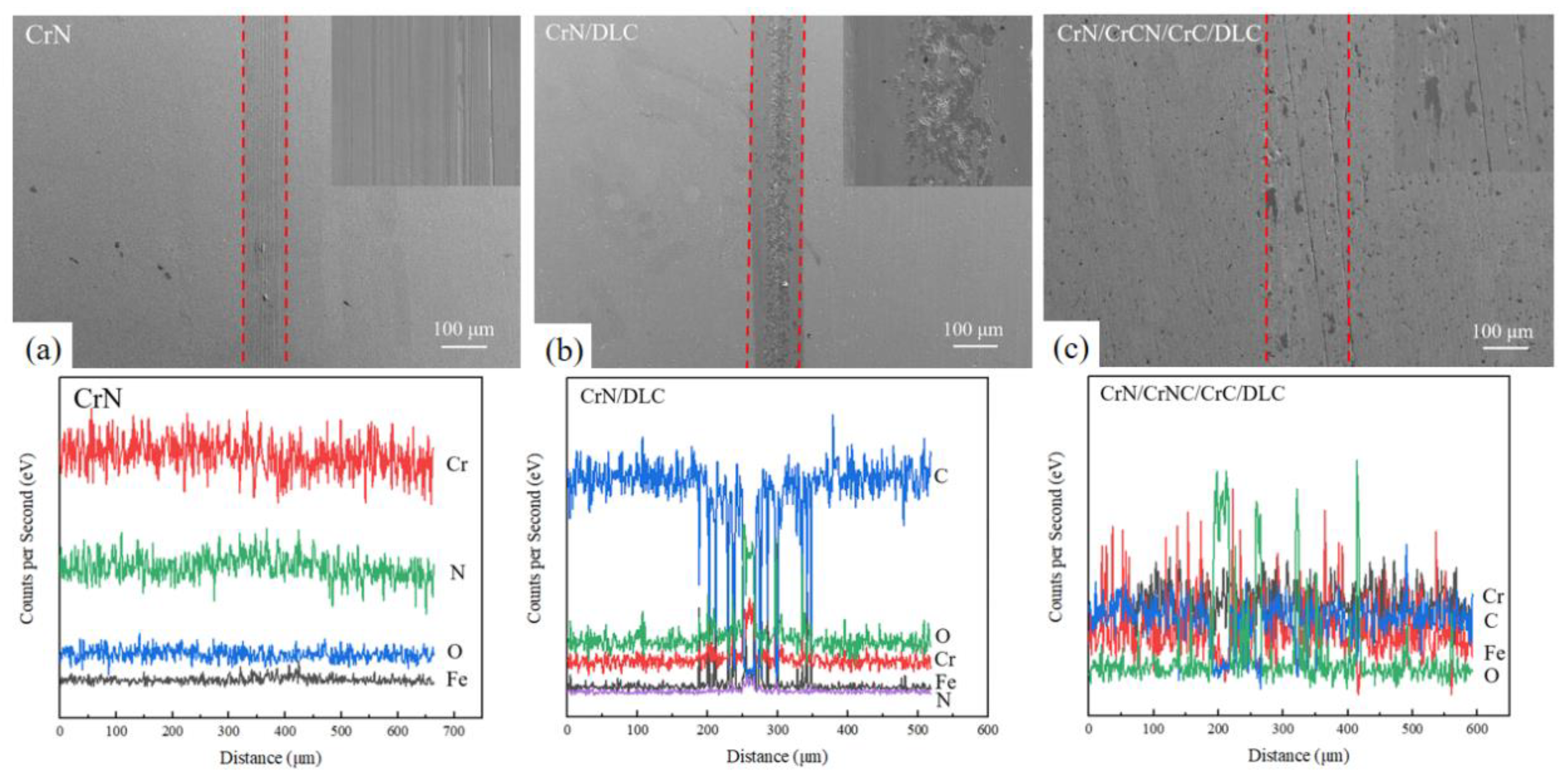
3.1. Morphology and Structural Analysis of Different Coatings

Initially, the surface morphology of the single CrN and DLC coatings is observed, as shown in Figure 2. The CrN coating exhibits a rough surface with the presence of micrometer-scale particle aggregation, hillocks, and pits, which are typical characteristics of CrN coatings prepared by PVD method [24]. The Cr droplets sputter from the target due to the local overheating of the target, and deposit on the deposited Cr bottoming film and then form hillocks on the surface of CrN coatings. Some of these hillocks drop from the film under the ion bombardment, leaving the pits on the surface. There are more particles and smaller clusters but fewer pits on the surface of duplex CrN/DLC coatings. The SEM morphology clearly shows that the surface of multi-layered DLC coatings is much smoother and denser without obvious pit-like defects and large particles or droplets.
The cross-section of these coatings is examined shown in Figure 2. The coatings all showed epitaxial columnar structures along the growth direction of the coating. Generally speaking, the coatings prepared by the PVD method often have a columnar structure. The thickness of the CrN coating is 1.33 μm, characterized by typical columnar crystal growth with small gaps between the columnar structures. In the duplex CrN/DLC coating, the CrN layer is approximately 540 nm and grown in a columnar crystal manner. The surface of the DLC layer is dense, with a thickness of about 600 nm. Small carbon atoms fill in the surface of the columnar CrN and the voids to form a denser duplex composite coating, which consequently reduces the surface defects. The interface between the CrN and DLC layers is unclear, suggesting possible element diffusion between layers. The total thickness of the multi-layered DLC coating reaches 4.02 μm, with the outer DLC layer being 1.59 μm thick. The interfaces between the multiple layers are not distinct, indicating the element diffusion and good interface bonding.
Figure 3 shows the XRD diffraction patterns of these three coatings. The strong diffraction peak at 44.4° mainly corresponds to the (200) plane of CrN, and the peak at 81.7° corresponds to Cr (211), indicating that CrN coatings grow with (200) as the preferred orientation and the underlying Cr layer grows preferentially in the (211) plane. The preferred orientation of Cr and CrN and the directional release of latent heat of crystallization lead to the growth pattern of columnar crystals as observed in Figure 2. Additionally, diffraction peaks for Cr3N4 are observed at 40.9° and 64.5°. Diffraction peaks at 63.5° and 76.2°, corresponding to the (110) and (311) crystal planes of CrN, respectively, indicate that the CrN coating grows preferentially in the (200) plane and has a polycrystalline structure with a small amount of nanocrystalline Cr3N4. From these XRD spectra, it can be found that CrN coatings have preferential growth orientations of (200), (311) and (110). Crystallographic theoretical analysis shows that the (200) orientation has one option of top termination where both chromium and nitrogen occupy the same plane, which will make a very dense structure [25]. Consequently, no obvious interface is observed between Cr and nitrides.
Generally, the energy driving force in the coating deposition process determines the grain growth orientation, which includes surface energy and residual stress [26]. There are metal Cr and different forms of its nitrides in the coating, which could improve the diffusion of Cr and the formation of transition interfaces. Otherwise, Cr and CrN have the same lattice type and can form a solid solution, which reduces the interface mismatch to a certain extent and improves the bonding strength and hardness of the coating [6,9]. As a result, there are no obvious interfaces in the middle layers of the multi-layer composited DLC coatings. As observed in Figure 2, there is an interface between DLC and the inner transition layers, but there is no obvious interface between nitrides and carbides of Cr.
Raman analysis indicates two characteristic peaks between 800 and 1800 cm−1, shown in Figure 4. Gaussian function decomposition identifies peaks near 1362 cm−1 (D peak) and 1380 cm−1 (G peak), which is typical of DLC characteristics [14]. The Raman data reveal that the ID/IG peak intensity ratio for the CrN/DLC coating is 1.01, with a half G peak full width (GFWHM) of 150 cm−1, while the multi-layer DLC coating has an ID/IG of 1.35 and a GFWHM of 123 cm−1, which means a higher sp3 bond content and higher disorder of the microstructure in the CrN/DLC coatings [14]. The multi-layer DLC coatings have a higher-order degree of structure that is a lower amorphization degree, suggesting a reduction in sp3 content. Additionally, it is calculated that the density of the CrN/DLC coating is 1.907 g/cm3, while the multi-layer DLC coating has a density of 1.61 g/cm3, indicating a denser structure with a higher content of sp3 carbon bonds. This indicates that a higher thickness or more transition layers of nitrides and carbides decreases the amorphization degree and sp3 bond content of DLC coatings.
To further analyze the chemical bonds in DLC coating, XPS analysis is performed on the multi-layer DLC coating, as shown in Figure 5. The C1s peak spectrum of multi-layer DLC coating is exhibited in Figure 5b, which could be decomposed into a C–O bond peak at 286.49 eV, a C–C sp3 bond peak at 285.01 eV, and a C–C sp2 bond peak at 284.49 eV by Gaussian fitting [27]. The sp3 bond content is 25.6%, obtained by calculating the area ratio of C–C sp3. Figure 5b shows the peak fitting of the Cr 2p peak in the multi-layer DLC coating, with the main peak at 574.5 eV corresponding to Cr-C bonds. Peaks at 576 eV, 581 eV, and 587 eV correspond to different valence states of Cr-O, and 584 eV corresponds to the binding energy of Cr-N. The formation of Cr-O and C–O bonds may be related to the residual oxygen in the chamber. Furthermore, the Cr 2p peak indicates that Cr primarily exists in the coating as CrC (41.6%) and CrN (20.2%), with fewer chromium oxides. And it has been proven that the formation of Cr carbides in the coating helps reduce interface stress between the outer DLC layer and the intermediate CrC layer, enhancing the film–substrate bonding strength [28]. From Figure 5d, the co-presence of CrN and Cr2N are observed, at 396.7 eV and 397.4 eV, respectively, along with the presence of N-C bonds at 399.1 eV. These results on the bonding of N elements indicates that N primarily exists as different kinds of nitrides of Cr. Notably, the small amount of N-C bonds (11.6%) would be not conducive to the formation of carbon bonds in large networks, contributing to amorphization. Transition metal nitrides are typical interstitial compounds. The phase of Cr2N with a small amount can dissolve into CrN at room temperature to form a solid solution, which not only improves the hardness of the coating, but also improves the density of the coating [29].

3.2. Mechanical Properties of Coatings

The scratch morphology of the multi-layer DLC composite coatings is shown in Figure 6. During the continuous application of the load, cracks begin to form; when the first fine cracking of the coating appears, the critical load is named as Lc1. As the load continues to increase, micro-cracks begin to expand laterally and locally peel off, and the critical load is labeled as Lc2. The coating starts to peel extensively from the substrate at Lc3, and large bright white areas can be observed on both sides of the scratch, as shown in Figure 6. The value of Lc1 is difficult to determine, while the value of Lc2 is easy to confirm by local amplification of the scratch appearance. Lc2 is 13 N and Lc3 is 24.3 N here. As indicated by previous XRD and XPS analysis, the formation of different carbides and nitrides of metal Cr within the composite coating suggests that an elemental diffusion transition layer is potentially generated to form a gradient structure between coating layers, which effectively enhances the bonding strength of the coating [28]. Furthermore, the inner CrN layer grows in a columnar crystal structure, allowing outer carbon particles to embed into the micro-voids between the columns, making the coating denser and thus enhancing the overall adhesive strength.
The load–displacement curves of the multi-layer DLC composite coatings are measured using nanoindentation, as shown in Figure 7. The maximum penetration depth in the multi-layer DLC coatings is 298 nm, with a residual depth of 185 nm, and an elastic recovery rate We of 62%, indicating a good elastic deformation capacity. The hardness is 10.99 GPa and the elastic modulus is 285.06 GPa, proving a significant increase in hardness after the deposition of the DLC coatings. This is also related to the sp3 bonds and amorphization degree, as mentioned in Raman analysis. Using the parameter H3/E2, it is possible to estimate the plastic deformation of this coating. The H/E and H3/E2 ratios of the composite DLC coatings are 0.038 and 0.016, respectively, demonstrating the coating’s excellent ability to resist crack formation. The existence of Cr and CrN inter-layers with body-centered cubic structure contributes to the resistance to plastic deformation of the composited DLC coatings. It is known that the effective role of increasing the number of interfaces in amulti-layer coating can be explained as a factor prohibiting the spread of dislocations, cracks, and joints of pin-holes [9,28]. The transition layers and solid solution that may form between interfaces may also be another reason for increasing hardness and elasticity, as mentioned in XPS analysis.
The friction and wear performance of different coatings are analyzed, and Figure 8a shows the coefficient of friction (COF) curves for single CrN coating, duplex CrN/DLC coating, and multi-layer DLC composite coating under dry friction testing conditions. The COF for the substrate, single CrN, duplex CrN/DLC, and multi-layer DLC coatings are 0.56, 0.48, 0.15, and 0.13, indicating that depositing of CrN and composited DLC coatings significantly reduces the COF, and the multi-layer composite DLC coating shows the lowest COF. It is known that graphite is an excellent solid lubricating material, and the self-lubricating role of the sp2-C bond in DLC coatings is important for decreasing the COF. Figure 8b,c show the COF curves of the coating and substrate in the deionized water and seawater testing conditions, respectively. Compared to the dry wear process, the COF of the substrate, CrN coating, and DLC coatings in the deionized water are 0.46, 0.24, 0.11, and 0.10, which are much smaller and stable as observed in Figure 8b. Furthermore, the COF for the substrate, CrN coating, and DLC coatings in the seawater are 0.35, 0.16, 0.08, and 0.09, indicating that the COFs are further decreased in the seawater. Additionally, no significant fluctuations in the COF of DLC coatings are observed across these three friction-testing conditions, proving that the duplex DLC and the multi-layer DLC coatings can decrease and maintain a stable COF.
It is known that the COF of the single CrN coatings is related to the surface roughness and hardness [30]. As previously mentioned, due to the rough surface of the single CrN coating with the presence of particles, pits and other defects, the COF is relatively higher with continuous fluctuations. However, the friction and wear properties of DLC are closely related to hardness, plastic deformation resistance, and residual stress [27]. The COF of the duplex CrN/DLC coating and multi-layer composited DLC coating are 0.08 and 0.09, respectively. Due to the lubricating effect from sp2 carbon bonds and high hardness from the sp3 carbon bond of CrN/DLC and multi-layer DLC coatings, the COFs are both reduced. And the rise of frictional temperature may also accelerate the transformation process from sp3 to sp2 carbon, which will further maintain the stable lower COF. It is proven that, in spite of the fact that hardness is regarded as the primary material property for defining wear resistance, the intrinsic Young modulus of the coatings is also found to have a combined influence [5]. The composited DLC coatings is observed to have high H/E, H3/E2 indicating high resistance against the onset and spread of cracks and higher nano hardness for blocking the movement of dislocations and microcracks [31]. Consequently, the friction resistance and wear resistance to deformation are to be expected in multi-layer DLC coatings. Moreover, the increase in sp2 bond content in the multi-layer composited DLC would also lead to a decreased friction coefficient and good wear resistance.
The analysis of wear mark morphology indicates that in dry wear testing conditions, CrN and DLC coatings exhibit different wear mechanisms, shown in Figure 9. The single CrN coating has a wider and rougher wear track, with a large number of adhesive grains along the track, indicating adhesive wear occurrences. This may be due to the detaching of the friction pair of the GCr15 ball with relative lower hardness during relative motion on the local surface, forming abrasive particles. These adhesive bonds eventually shear off and take away part of debris during the friction process. As a result, the coating is severely worn and causes damage to the coating in the form of furrows, as observed in wear morphology. Consequently, there exist many adhesive bonds on the wear track of the CrN coating, implying an adhesive wear mechanism during the friction test [32]. Elemental analysis of the wear marks shows a decrease in Cr and N content and an increase in O and Fe content, indicating significant wear and the appearance of frictional oxidation.
However, the wear track of the CrN/DLC coating is smoother, and little wear debris is found alongside the wear track. EDS analysis also shows a decrease in C content at the wear marks, indicating localized peeling and slight increases in O and Fe content due to frictional oxidation. As with the previous analysis, the high sp3 bond content and amorphization with limited overall thickness of duplex CrN/DLC coating leads to high hardness with certain fragility and induces partial wearing during friction, too. The wear marks of the multi-layer DLC coating are wider, cleaner, and smoother, with no significant changes in element contents, suggesting that the coating remains stable and intact without peeling or failure. Even visible debris is hard to see, as is the color change caused by the peeling of the coating, which indicates the good wear resistance of this composited DLC coating with a lower COF. This is possibly due to the solid lubrication from the higher sp2 bond content and the much more ordered structure as analyzed in Raman results, making the coating relatively softer, allowing deeper and wider indentation by the wear ball. And the thickness and hardness of this multi-layer DLC coating are both high enough to supply good wear resistance.
The above analysis under dry friction conditions shows that the CrN coating undergoes frictional oxidation, while the CrN/DLC coating, with limited thickness, experiences partial frictional peel failure, and the multi-layer composite DLC coating exhibits the best wear resistance, providing long-term effective protection for the substrate.
Figure 10 and Figure 11 show the wear mark morphology of the coatings after wear in the deionized water and seawater, respectively. Compared to dry friction, all their COFs are reduced and the wear marks become narrower, except for the multi-layer DLC coatings. The lubrication effect of water as a lubricant independent of lubrication state cannot be ignored when friction and wear are carried out in solution [33]. It has been proven that water plays an essential role as a lubricant on carbon-based materials [34]. And the outer DLC coating could effectively provide solid lubrication in a wet environment, and then reduce both the COF and wear rate [35]. However, after wear in the deionized water, the fluctuating distribution of Cr and O elements in the wear marks is observed, along with a decrease in N content and an increase in Fe content, which indicates local worn-out failure of coatings and occurrence of oxidation in CrN and CrN/DLC coatings. And there is also obvious mutation of the O element in the wear marks of multi-layer composite DLC coatings, reflecting the formation of oxides, too. The graphite in the outer DLC coatings may be washed away by the deionized water during the friction process, which reduces the lubrication effect and leads to relatively increased surface wear loss. The growth defects such as pits, flakes, and the columnar porous microstructure of CrN coatings would be filled with solutions, which is another key factor in decreasing the COF and influencing the wear resistance in solutions. The existence of tiny gaps caused by the columnar structure of multi-layer coatings makes it possible for deionized water to penetrate into the inner coating during the friction process, resulting in frictional oxidation and even partial detachment [8,27].
Notably, the COF of CrN decreases from 0.48 in dry friction conditions to 0.16 in the seawater, and there is a stable and continuous oxygen distribution on the surface, as shown in Figure 11. The wear mark analysis after friction in the seawater shows that CrN coating remains intact after 30 min of friction, and the wear mark gets smoother and narrower, as gaps in the columnar structure enable seawater infiltration through the coating [25], which promotes the formation of a uniform passivation film, decreasing the COF to prevent further corrosion wear occurrence. It has been found that the decline in the COF for increasingly rough surfaces may be attributed to the decrease in the real contact area by deformation of a thin subsurface layer in solutions [36]. The existence of multiple ions in seawater is conducive to the formation of the viscoelastic film, so the COF of these coatings in the seawater is further reduced. Furthermore, the much better corrosion wear properties of the composited DLC coatings may be related to the denser microstructure and sp2 bonds in carbon coatings. And the local oxidation in CrN/DLC and multi-layer composited DLC coatings are both further decreased due to the existence of coherent interfaces [32], and their wear marks get much narrower compared to those in the deionized water. Considering the presence of Cr in these three coatings, as investigated in XRD results, a dense oxide passivation film may form on the coating surface, induced by the large number of negative ions in seawater, which would prevent seawater seeping through surface gaps and reduces the COF and wear loss.
However, the wear mark analysis of the CrN/DLC coating in the deionized water and seawater environments reveals localized peeling, with a decrease in C content and an increase in O content, indicating that the outer carbon film serves as an effective barrier for substrate protection. The elemental distribution at the wear marks of the multi-layer composited DLC coating shows no significant changes, proving that this kind of multi-layer DLC coating remains intact in both seawater and deionized water, exhibiting better wear resistance. This is related to the sufficient thickness of these coatings combined with the low friction coefficient from DLC film and the corrosion resistance due to the presence of intermediate CrN gradient layers. This result indicates that Further CrN coating and coatings including CrN have excellent tribo-corrosion performance in the seawater.

4. Conclusions

CrN grows in a columnar structure and has a relatively rough surface with many defects. The outer DLC coating makes a smooth surface of composited coatings. Under dry friction conditions, the single CrN coating has a friction coefficient of 0.48 and suffers from severe plowing wear, and the coating fails due to friction and peeling. The sp2 bond in Further outer DLC coating has good lubrication, which reduces the friction coefficient of the CrN/DLC coating to 0.15, but the coating experiences localized wear due to limited thickness. The multi-layer composited DLC coating achieves the lowest friction coefficient of 0.13 and remains stable in dry friction. In the deionized water and seawater testing conditions, the friction coefficients of the DLC and CrN coatings are further reduced. CrN coatings have good corrosion and friction resistance in seawater, with a decreased friction coefficient of 0.16. The friction coefficient is further reduced to 0.08 in DLC coatings, which maintain good tribo-corrosion resistance.

Author Contributions

Methodology, X.Y.; Resources, F.G., L.D., Y.L. and B.Z.; Data curation, T.H.; Writing—review & editing, S.Z. All authors have read and agreed to the published version of the manuscript.

Funding

This research was funded by the Natural Science Foundation of China (Grant No. 51861031).

Institutional Review Board Statement

Not applicable.

Informed Consent Statement

Not applicable.

Data Availability Statement

Data are contained within the article.

Conflicts of Interest

Authors Longjie Dai and Yi Liu was employed by the company Qingdao Choho Chain Transmission Co., Ltd. The remaining authors declare that the research was conducted in the absence of any commercial or financial relationships that could be construed as a potential conflict of interest.

References

  1. Soleimani, M.; Fattah-alhosseini, A.; Elmkhah, H.; Babaei, K.; Imantalab, O. A comparison of tribological and corrosion behavior of PVD-deposited CrN/CrAlN and CrCN/CrAlCN nanostructured coatings. Ceram. Int. 2023, 49, 5029–5041. [Google Scholar] [CrossRef]
  2. Hongxi, L.; Yehua, J.; Rong, Z.; Baoyin, T. Wear behaviour and rolling contact fatigue life of Ti/TiN/DLC multilayer films fabricated on bearing steel by PIIID. Vacuum 2012, 86, 848–853. [Google Scholar] [CrossRef]
  3. Wu, G.; Sun, L.; Dai, W.; Song, L.; Wang, A. Influence of interlayers on corrosion resistance of diamond-like carbon coating on magnesium alloy. Surf. Coat. Technol. 2010, 204, 2193–2196. [Google Scholar] [CrossRef]
  4. Liu, E.; Yu, B.; Xue, Y.; Pu, J.; Du, S.; Du, H. Microstructure and mechanical properties of a CrCN/Cr multilayer film. Mater. Res. Express 2020, 7, 096406. [Google Scholar] [CrossRef]
  5. Valleti, K.; Miryalkar, P.; L, R.K. Efficacy of TiCrN/DLC coatings for service life enhancement of stamping dies. Vacuum 2023, 217, 112534. [Google Scholar] [CrossRef]
  6. Gilewicz, A.; Warcholinski, B. Tribological properties of CrCN/CrN multilayer coatings. Tribol. Int. 2014, 80, 34–40. [Google Scholar] [CrossRef]
  7. Atmani, T.D.; Bouamerene, M.-S.; Gaceb, M.; Nouveau, C.; Aknouche, H. Improvement of the tribological behavior of TiN/CrN multilayer coatings by modulation wavelength variation. Tribol. Int. 2024, 192, 109226. [Google Scholar] [CrossRef]
  8. Vicen, M.; Kajanek, D.; Bokuvka, O.; Nikolic, R.; Medvecka, D. Resistance of the CrN coating to wear and corrosion. Transp. Res. Procedia 2023, 74, 426–433. [Google Scholar] [CrossRef]
  9. Jasempoor, F.; Elmkhah, H.; Imantalab, O.; Fattah-Alhosseini, A. Comparison of electrochemical behavior of CrN single-layer coating and Cr/CrN nanolayered coating produced by cathodic arc evaporation physical vapor deposition. Int. J. Appl. Ceram. Technol. 2022, 19, 2222–2235. [Google Scholar] [CrossRef]
  10. Madej, M. The effect of TiN and CrN interlayers on the tribological behavior of DLC coatings. Wear 2014, 317, 179–187. [Google Scholar] [CrossRef]
  11. Duminica, F.D.; Belchi, R.; Libralesso, L.; Mercier, D. Investigation of Cr(N)/DLC multilayer coatings elaborated by PVD for high wear resistance and low friction applications. Surf. Coat. Technol. 2018, 337, 396–403. [Google Scholar] [CrossRef]
  12. Liu, X.; Zhang, W.; Sun, G. The influence of textured interface on DLC films prepared by vacuum arc. Surf. Coat. Technol. 2019, 365, 143–151. [Google Scholar] [CrossRef]
  13. Guo, C.Q.; Li, H.Q.; Peng, Y.L.; Dai, M.J.; Lin, S.S.; Shi, Q.; Wei, C.B. Residual stress and tribological behavior of hydrogen-free Al-DLC films prepared by HiPIMS under different bias voltages. Surf. Coat. Technol. 2022, 445, 128713. [Google Scholar] [CrossRef]
  14. Casiraghi, C.; Ferrari, A.C.; Robertson, J. Raman spectroscopy of hydrogenated amorphous carbons. Phys. Rev. B 2005, 72, 085401. [Google Scholar] [CrossRef]
  15. Wang, Y.; Gao, K.; Zhang, B.; Wang, Q.; Zhang, J. Structure effects of sp2-rich carbon films under super-low friction contact. Carbon 2018, 137, 49–56. [Google Scholar] [CrossRef]
  16. Wang, J.; Wang, L.; Chen, H.; Wang, H. Molecular dynamics simulation of friction in DLC films with different sp3 contents. Tribol. Int. 2023, 190, 109050. [Google Scholar] [CrossRef]
  17. Wang, L.J.; Chen, H.; Liu, Y.; Zhu, R.W. Interface-dominated deformation mechanisms in Cr/CrN/Cr-DLC multilayer triggered by nanoindentation. Mater. Sci. Eng. A 2023, 887, 145745. [Google Scholar] [CrossRef]
  18. Kong, W.C.; Yu, Z.; Hu, J. Electrochemical performance and corrosion mechanism of Cr-DLC coating on nitrided Ti6Al4V alloy by magnetron sputtering. Diamond. Relat. Mater. 2021, 116, 108398. [Google Scholar]
  19. Kolawole, F.O.; Kolawole, S.K.; Bello, S.A.; Yakubu, S.; Adigun, O.D.; Owa, A.F.; Umunakwe, R.; Adebayo, A.O.; Madueke, C.I. Fracture toughness of duplex CrN/DLC and nano-multilayer DLC-W deposited on valve tappet via hybrid PVD and PECVD. Sadhana 2024, 49, 127. [Google Scholar] [CrossRef]
  20. Liang, S.; He, D.; Shang, L.; Li, W.; Zhang, C.; Shao, L.; Seniuts, U.; Viktor, Z. Effect of cermet interlayer on the electrochemical behavior of Cr3C2-NiCr/DLC duplex coating. Surf. Coat. Technol. 2023, 469, 13. [Google Scholar] [CrossRef]
  21. Hu, X.; Qiu, L.; Pan, X.; Zhang, J.; Li, X.; Zhang, S.; Dong, C. Nitrogen diffusion mechanism, microstructure and mechanical properties of thick Cr/CrN multilayer prepared by arc deposition system. Vacuum 2022, 199, 110902. [Google Scholar] [CrossRef]
  22. Zhong, W.; Wang, H.; Ma, L.; Zhang, C. Impact Abrasive Wear of Cr/W-DLC/DLC Multilayer Films at Various Temperatures. Metals 2022, 12, 1981. [Google Scholar] [CrossRef]
  23. Waldl, H.; Hans, M.; Schiester, M.; Primetzhofer, D.; Burtscher, M.; Schalk, N.; Tkadletz, M. Decomposition of CrN induced by laser-assisted atom probe tomography. Ultramicroscopy 2023, 246, 113673. [Google Scholar] [CrossRef] [PubMed]
  24. Çelik, G.A.; Fountas, K.; Atapek, S.H.; Kamoutsi, E.; Polat, S.; Zervaki, A.D. Investigation of Adhesion and Tribological Performance of CrN-, AlTiN-, and CrN/AlTiN-Coated X45CrMoV5-3-1 Tool Steel. J. Mater. Eng. Perform. 2023, 32, 7527–7544. [Google Scholar] [CrossRef]
  25. Fite, S.; Zukerman, I.; Shabat, A.B.; Barzilai, S. Hydrogen protection using CrN coatings: Experimental and theoretical study. Surf. Interfaces 2023, 37, 102629. [Google Scholar] [CrossRef]
  26. Li, Z.D.; Zhan, H.; Xu, T.Y.; Bao, M.Y.; Li, B.H.; Wang, R.J. Influence of Cr Interlayer Thickness on Residual Stress and Adhesion of Cr-DLC Multilayer Structure Films. Rare Met. Mater. Eng. 2022, 51, 1195–1202. [Google Scholar]
  27. Zhao, Y.; Xu, F.; Zhang, D.; Xu, J.; Shi, X.; Sun, S.; Zhao, W.; Gao, C.; Zuo, D. Enhanced tribological and corrosion properties of DLC/CrN multilayer films deposited by HPPMS. Ceram. Int. 2022, 48, 25569–25577. [Google Scholar] [CrossRef]
  28. Qi, Y.; Liang, W.; Miao, Q.; Lin, H.; Yi, J.; Gao, X.; Song, Y. Characterization of a CrN/Cr gradient coating deposited on carbon steel and synergistic erosion-corrosion behavior in liquid‒solid flow impingement. Ceram. Int. 2023, 49, 33925–33933. [Google Scholar] [CrossRef]
  29. Xu, S.; Zhao, Z.; Zhou, Y.; Chen, D.; Zhang, K.; Li, T.; Zhou, Y.; Wang, A. Interface feature via key factor on adhesion of CrN multilayer and alloy substrate. Appl. Surf. Sci. 2023, 630, 157492. [Google Scholar] [CrossRef]
  30. Jasempoor, F.; Elmkhah, H.; Imantalab, O.; Fattah-alhosseini, A. Improving the mechanical, tribological, and electrochemical behavior of AISI 304 stainless steel by applying CrN single layer and Cr/CrN multilayer coatings. Wear 2022, 504, 204425. [Google Scholar] [CrossRef]
  31. Liu, L.; Shao, L.; Li, W.; Shang, L.; Zhang, C.; Song, Q. Improving the tribological behavior of CrN film by PVD/HVOF design. Surf. Coat. Technol. 2023, 475, 130171. [Google Scholar] [CrossRef]
  32. Sui, X.; Liu, J.; Zhang, S.; Yang, J.; Hao, J. Microstructure, mechanical and tribological characterization of CrN/DLC/Cr-DLC multilayer coating with improved adhesive wear resistance. Appl. Surf. Sci. 2018, 439, 24–32. [Google Scholar] [CrossRef]
  33. Guo, F.; Tian, Y.; Liu, Y.; Wang, Y.M. Unexpected friction behaviours due to capillary and adhesion effects. Sci. Rep. 2017, 7, 148. [Google Scholar] [CrossRef] [PubMed]
  34. Kim, J.-E.; Choi, J.I.J.; Kim, J.; Mun, B.S.; Kim, K.-J.; Par, J.Y. In-Situ Nanotribological Properties of Ultrananocrystalline Diamond Films Investigated with Ambient Pressure Atomic Force Microscopy. J. Phys. Chem. C 2021, 125, 6909–6915. [Google Scholar] [CrossRef]
  35. Ye, Y.W.; Wang, Y.X.; Ma, X.L.; Zhang, D.W.; Wang, L.P.; Li, X.G. Tribocorrosion behaviors of multilayer PVD DLC coated 304L stainless steel in seawater. Diamond. Relat. Mater. 2017, 79, 70–78. [Google Scholar] [CrossRef]
  36. Ules, T.; Hausberger, A.; Grießer, M.; Schlögl, S.; Gruber, D.P. Introduction of a New In-Situ Measurement System for the Study of Touch-Feel Relevant Surface Properties. Polymers 2020, 12, 1380. [Google Scholar] [CrossRef]
Figure 1. Deposition time and composition of different coatings.
Coatings 14 01002 g001
Figure 2. Surface and cross-sectional morphology of different coatings: (a) CrN; (b) CrN/DLC; (c) Multi-layer DLC.
Coatings 14 01002 g002
Figure 3. X-ray diffraction pattern of coatings.
Coatings 14 01002 g003
Figure 4. Raman spectrum of coatings: (a) CrN/DLC; (b) Multi-layer DLC.
Coatings 14 01002 g004
Figure 5. XPS diagram of multi-layer coating: (a) Total spectrum of elements; (b) C 1s; (c) Cr 2p; (d) N 1s.
Coatings 14 01002 g005
Figure 6. Scratches and bonding force of multi-layer DLC coating.
Coatings 14 01002 g006
Figure 7. Indentation depth–load curve of multi-layer DLC coating.
Coatings 14 01002 g007
Figure 8. Friction coefficient curves of coatings and substrate under different testing conditions: (a) Dry friction; (b) Deionized water; (c) Seawater.
Coatings 14 01002 g008
Figure 9. Wear morphology and the corresponding EDS elemental analysis of coatings after dry friction: (a) CrN; (b) CrN/DLC; (c) Multi-layer DLC.
Coatings 14 01002 g009
Figure 10. Wear morphology and the corresponding EDS elemental analysis of coatings after wear in deionized water: (a) CrN; (b) CrN/DLC; (c) Multi-layer DLC.
Coatings 14 01002 g010
Figure 11. Wear morphology and the corresponding EDS elemental analysis of coatings after wear in seawater: (a) CrN; (b) CrN/DLC; (c) Multi-layer DLC.
Coatings 14 01002 g011
Table 1. Process parameters of coating preparation.
ParameterTargets Current and Gas FlowDepositing Time/min
CoatingsCr/AC/AN2/sccm
CrNCr3offoff10
CrN4off15 90
CrN/DLCCr3offoff25
CrN4off15 25
DLCoff4off90
Multi-layer DLCCr3offoff25
CrN4off15 25
CrNC341525
CrC34off25
DLCoff4off120
Disclaimer/Publisher’s Note: The statements, opinions and data contained in all publications are solely those of the individual author(s) and contributor(s) and not of MDPI and/or the editor(s). MDPI and/or the editor(s) disclaim responsibility for any injury to people or property resulting from any ideas, methods, instructions or products referred to in the content.

