Article

Use of 2D Sulfide and Oxide Compounds as Functional Semiconducting Pigments in Protective Organic Coatings Containing Zinc Dust

1
Faculty of Chemical Technology, University of Pardubice, Studentská 573, 532 10 Pardubice, Czech Republic
2
Jan Perner Transport Faculty, Educational and Research Centre in Transport, University of Pardubice, Doubravice 41, 533 53 Pardubice, Czech Republic
*
Author to whom correspondence should be addressed.
Coatings 2024, 14(8), 1009; https://doi.org/10.3390/coatings14081009
Submission received: 8 July 2024 / Revised: 23 July 2024 / Accepted: 2 August 2024 / Published: 8 August 2024

Abstract

:
Within this study, the influence of particles of different types, natures, and sizes on the mechanical and corrosion resistance of pigmented systems containing spherical zinc was studied. For this study, prominent representatives from the group of transition metal dichalcogenides (MoS2, WS2), layered transition metal oxides (MoO3, WO3), and other semiconductor materials (ZnS and ZnO) were used. The layered ultra-thin structure of these particles was predisposed to provide enhanced mechanical and anti-corrosion performance. The mechanical properties of the studied coatings were tested using standardized mechanical tests, while the anti-corrosion performance of these coatings was studied using standardized cyclic corrosion tests and the linear polarization electrochemical technique. The results of the experimental techniques bring completely original knowledge about the action of these pigments in paint systems pigmented with zinc. The results of experimental techniques have shown enhancement and an increase in both mechanical and anti-corrosion performance when using these special types of inorganic pigments. In particular, with organic coatings pigmented with MoO3, there was an increase in mechanical resistance mainly due to its morphology and layered structure. In addition, a significant enhancement of the anti-corrosion efficiency was noted for this type of organic coating due to the enhancement of individual types of action mechanisms typical and proven for zinc-pigmented systems. These original findings can be used in the search for possibilities to reduce the zinc content in zinc-pigmented organic coatings. This partial replacement of zinc particles leads not only to a reduction in the zinc content in the system but also to a significant strengthening of the mechanical resistance and an increase in the corrosion efficiency of the system.

Graphical Abstract

1. Introduction

Corrosion is a slow chemical or electrochemical process in which a metal interacts with a corrosive medium (water, oxygen, chloride ions, etc.), resulting in the loss of its original properties such as high hardness, strength, and luster, leading to huge economic losses and social impacts. The most common and versatile method of protecting metallic materials from corrosion is the application of organic coatings, which protect the metal substrate through four mechanisms—barrier, adhesion, inhibition, and electrochemical action. The combination of these four mechanisms in the coating film leads to the resulting corrosion protection [1,2,3,4].
Basic zinc-pigmented coatings use electrochemical, filtration, and neutralization protection mechanisms in addition to the barrier effect for corrosion protection of metallic materials, most often steel. However, the zinc particles in zinc-pigmented protective organic coatings protect the steel substrate electrochemically (cathodic protection) only in the first phase of its action. Zinc is electrochemically less noble than steel or iron, and if the connection between the individual zinc particles and the zinc coating and the steel is sufficiently conductive, mutual polarization occurs. The zinc contained in the coating film, thus, becomes the anode and the steel substrate the cathode. In the event of a breach in the coating film and electrolyte penetration, cathodic protection is triggered at the point of breach, zinc begins to oxidize, and its corrosion products begin to heal the breached area. The corrosion fumes perfectly seal all cracks and pores in the coating film, resulting in a very compact and perfectly adhesive layer, applying a barrier protection mechanism that is resistant to normal atmospheric influences. The barrier mechanism is strengthened by a filtering and neutralizing mechanism/effect, which results in the separation of oxygen or other corrosion stimulants (Cl, SO42−) from the electrolyte penetrating the undamaged zinc-pigmented coating film. As a result of the reaction of these corrosion stimulators with the zinc metal particles present in the coating film, zinc corrosion products are formed, which reinforce the barrier mechanism. Although zinc coatings are less toxic compared to coatings containing lead or chromate compounds, zinc corrosion products are classified as hazardous to the aquatic environment. For this reason, there are efforts to reduce the zinc content of coatings with other non-toxic pigments to achieve high corrosion protection [5,6,7,8,9,10,11,12].
Two-dimensional (2D) materials belong to a large and diverse class of single-layer carbonaceous materials, dichalcogenides, phosphides, nitrides, halides, one or more layered transition metal oxides, and layered silicate materials [13,14,15]. These materials are exceptional due to their unique physical and chemical properties, structural diversity, large surface area-to-volume ratio, and good electrical conductivity, which make them applicable in a number of industrial areas—optics, electronics, catalysis, sensors, and power units (batteries, supercapacitors, or solar cells) [16,17,18]. Two-dimensional materials have recently attracted more and more attention in the field of anti-corrosion protection [19].
Transition metal dichalcogenides are 2D layered materials with ultrathin structures whose properties are highly dependent on the degree of crystallinity, number of layers, and layering sequences in their crystals and thin films [15,20]. With the growing interest in layered transition metal dichalcogenides, MoS2 has taken a unique place due to its exceptional properties and structure as a graphene analog. Layers of molybdenum atoms are arranged in a hexagonal array sandwiched between layers of sulfur, which are held by strong covalent bonds, while Van der Waals interactions exist between the sulfur layers. Due to this unique lamellar structure, MoS2 has good corrosion resistance similar to graphene. Still, unlike graphene, MoS2 is a semiconductor with a relatively high forbidden band and, therefore, has no effect on the electrical conductivity of the epoxy resin [15,19,20,21,22]. Tungsten disulfide, also known as “tungstenite”, is another representative of the semiconductor layered group. WS2, like MoS2, has trigonal prismatic coordination, perfect anisotropy, and graphene-like properties [23]. As a multilayer semiconductor material, it has a forbidden band value of 1.10–1.35 eV, while WS2 monolayers have 2.05 eV. The monolayers also exhibit strong photoluminescence. WS2 is a layered material that can form nanotubes characterized by high mechanical strength, impact resistance, and willingness to integrate with host matrices. MoS2 and WS2 are also known for their excellent tribological properties [24,25]. Their 2D lamellar structure results in an ultra-low coefficient of friction due to the relative shear of the van der Waals layers [26].
Single or multilayer transition metal oxides have a relatively long history; they are found in many minerals and are widely used as construction materials, pigments, lubricants, and in many other applications. In single or multilayer oxides, the transition metal electrons are strongly attracted to oxygen, and consequently, their physical, chemical, and structural properties are strongly determined by the correlated d electrons. These materials exhibit different physical and chemical properties compared to their bulk counterparts, giving rise to several remarkable properties such as high-temperature superconductivity, multiferroicity, and unique optical, mechanical, and thermal phenomena [13,27]. MoO3 is an n-type semiconductor material with a relatively broad forbidden band of ~3.2 eV. As a cheap and chemically stable compound with a unique layered structure, MoO3 plays an important role in many industrial applications [28]. Molybdenum oxide also interacts with electromagnetic radiation in the UV region. Due to its photochromic and electrochromic properties, it is mainly used in electronics and as a photocatalyst. MoO3 is also highly sensitive to various gases (NO, NO2, CO, and NH3). It has, therefore, also been investigated in recent years for its possible use in thin film form as part of gas detectors [29,30]. Another representative of transition metal oxides is tungsten oxide. It is a semiconductor material with a forbidden band value ranging from 2.4 to 2.8 eV. WO3 is a polymorphic material that changes its crystal structure depending on temperature. The simplest structure for the stoichiometric expression of WO3 consists of corner octahedra, each with a centrally located tungsten atom surrounded by six oxygen atoms. Important properties of this material include high photoelectrochemical stability over a wide pH range (especially in the acidic region) and the ability to absorb electromagnetic radiation in the visible and UV regions [31,32,33].
Other important semiconductors include zinc oxide and zinc sulfide. Zinc oxide is an N-type semiconductor material with a relatively broad bandgap (3.4 EV) that is active in the UV region, which makes it suitable for a wide range of applications from photocatalysts and UV photodetectors to crosslinking agents for rubber production. ZnO also exhibits biological activity and is used as an antibacterial and fungicidal additive. It is also used as a white pigment with anti-corrosive properties due to its relatively high refractive index [34,35,36,37]. Zinc sulfide, like zinc oxide, is an N-type semiconductor material possessing a high refractive index, high dielectric constant, and unique photocatalytic properties. Due to its high refractive index, it finds application as a pigment in UV-curable coatings and for the production of photodetectors and photodiodes. ZnS is also used as an additive in plastics, where it serves as a flame retardant [38,39,40]. ZnS, together with BaSO4, is also represented in lithopone, which is produced by coprecipitation and subsequent calcination of a mixture of zinc sulfide and barium sulfate (ZnS content = 30%). This type of pigment combines the individual advantages of both types of compounds and is used in paint formulations [41,42].
Zinc-pigmented coatings are currently receiving increasing attention, mainly because of their high efficiency in corrosive environments with a high degree of aggressiveness. However, the high efficiency of zinc is also reflected in some of the shortcomings of the final organic coatings, such as lower mechanical resistance, and therefore, the reduction or replacement of a certain part in the coating with other pigments seems to be advisable. For this reason, the properties of coatings based on different types of binders with different morphologies of zinc pigment particles in the coating binder are studied [43,44,45]. A number of works also address the use of conductive polymers for their combination with zinc or even conductive polymers in the form of coated pigment particles in conductive polymer coatings. Zinc dust with different morphologies of zinc particles is also used for this purpose [46,47,48,49,50]. For systems pigmented with lamellar zinc, the reinforcing ability of lamellar particles was confirmed. The possibilities of using synthesized organic pigments containing metal cations in their structure were also studied with the aim of strengthening the properties of zinc-pigmented systems [51,52,53]. A number of studies have also focused on the use of other pigments with suitable electrochemical nobility or the addition of a special filler or conductive pigment in the formulation of zinc-pigmented coatings, where the aim is to increase the conductivity of the system and/or to increase the barrier efficiency of the coatings [52,53,54]. One such possibility appears to be using sulfide semi-conductive pigments or chemically active anti-corrosion pigments of the oxide type. The use of these types of pigments has demonstrably led to a strengthening of the anti-corrosion efficiency and a significant strengthening of the mechanical resistance of the systems, mainly due to the shape of the particles of these pigments.

2. Materials

Molybdenum disulfide (MoS2), molybdenum trioxide (MoO3), tungsten disulfide (WS2), tungsten trioxide (WO3), zinc sulfide (ZnS) and zinc oxide (ZnO) were from the company Merck KGaA, Darmstadt, Germany. Litopone—ZnS/BaSO4—was from 3P-CHEM s.r.o., Zbůch, Czech Republic. Zinc (Zn) was from Radka International s.r.o., Lázně Bohdaneč, Czech Republic. Epoxy ester resin WorléeDur D46 and sicative Valirex Mix 835 D60 were from 3P-CHEM s.r.o., Zbůch, Czech Republic. Loctite EA 9466 was from Ulbrich Hydroautomtik s.r.o., Brno, Czech Republic. Sodium chloride, ammonium sulfate, xylene, urotropine, hydrochloric acid, and chloroform were from PENTA s.r.o., Prague, Czech Republic. Q-panels were from the company Q-LAB DEUTSCHLAND GMBH, Saarbrucken, Germany.

3. Experimental

3.1. Characterization of the Binder and Pigments by Methods Used in the Coatings Field

3.1.1. Characterization and Specification of the Epoxy Ester Resin

An epoxy ester resin with the commercial name WorléeDur D46 was used as a binder to prepare model paint. This type of binder was specified by the following parameters: dry matter; color according to DIN ISO 4630 [55]; acid value according to ISO 2114 [56]; and viscosity by Rheometer. The infrared spectroscopy (FTIR) of the used dry film of binder was measured with Nicolet iS50 (Thermo Fisher Scientific, Waltham, MA, USA) using the ATR technique on the diamond crystal (Thermo Fisher Scientific, Waltham, MA, USA).

3.1.2. Determination of Physico-Chemical Properties of Studied Inorganic Pigments

The density of eight types of studied inorganic pigments was determined using a Micromeritics AutoPycnometer 1340 (Micromeritics Instrument Corp. Norcross, GA, USA). Oil absorption of studied inorganic pigments was measured by the “pestle–mortar” method. The measured results of the above determinations were used to calculate the critical pigment volume concentration (CPVC).

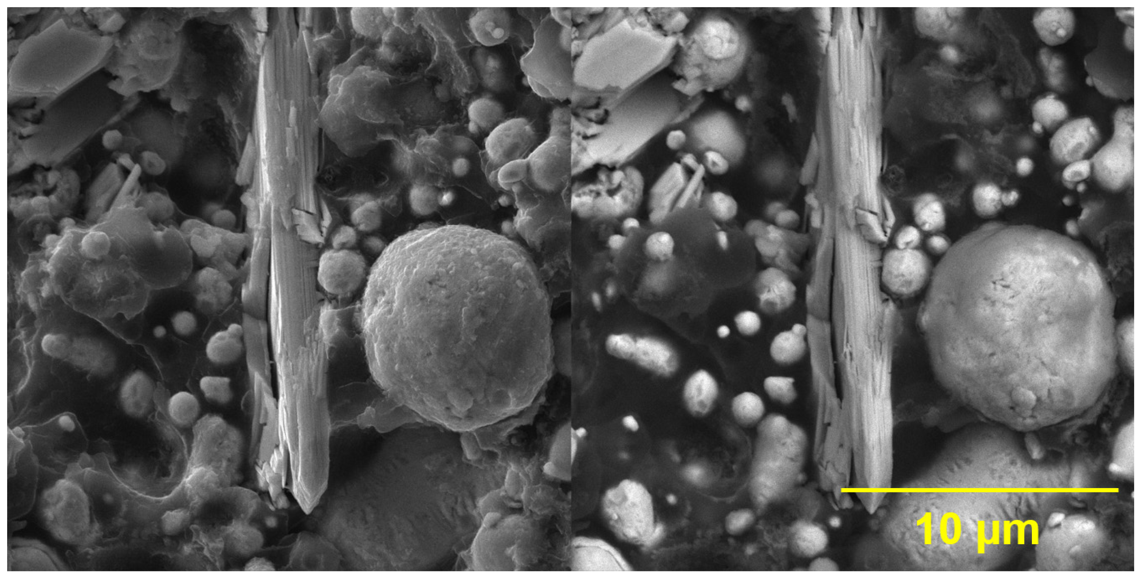
3.1.3. SEM and EDX Measurements of Pigments

The scanning electron microscopy LYRA 3 (SEM) (Tescan, Brno, Czech Republic) scans and elemental composition data of studied pigments were obtained using scanning electron microscope equipped with EDX analyzer Aztec X-Max 20 (Oxford Instruments, Oxford, UK). Samples were coated with a 20 nm carbon conductive layer (Leica ACE 200, Wetzlar, Germany) and measured on five 200 μm × 200 μm areas at 20 kV accelerating voltage. The results were averaged, and the error bars represent standard deviations of measured values. The pigments were coated with an 18 nm gold conductive layer, and SEM scans of the studied samples were acquired at 10 kV acceleration voltage.

3.2. Preparation of Formulated Model Coating Systems and Their Application

Eight types of inorganic pigments (WS2, WO3, ZnS, ZnO, MoS2, MoO3, and ZnS/BaSO4) were used together with powder zinc (spherical type) to formulate model paints. The model paints were formulated at a pigment volume concentration of studied inorganic pigments PVC = 3%, 5%, and 10% and subsequently were model paints also pigmented with powder metal zinc with spherical particle shape to maintain a constant concentration of solids so that the pigment volume concentration to critical pigment volume concentration ratio was PVC/CPVC = 0.60.
The model paints were prepared using a Dissolver-type apparatus (Dispermat® CN30-F2, VMA-Getzmann GMBH, Reichshol, Germany) at 4500 rpm/45 min using dispersion beads with a diameter of 2.85–3.45 mm. Valirex Mix 835 D60 was used as a drying agent in the amount recommended by the resin manufacturer (specifically 0.1% converted to 100% alkyd resin). Valirex Mix 835 D60 is a mixed metal carboxylate based on cobalt, calcium, and zirconium, diluted in D60 with a total metal content of 8.8%. The viscosity of the prepared model paints was adjusted using xylene.
The tested inorganic materials are easily dispersible, and their tendency to agglomerate was not noted. The 2D pigments have a positive effect on the stability of coating systems in liquid form. These pigments slow down the rate of particle sedimentation due to the mutual interaction of individual particles.
After preparation, the prepared model paints containing individual types of studied inorganic pigments in combination with spherical zinc were applied to standard glass and steel Q-Panels (low-carbon steel panels). ZQD-SP-104171 steel panels were used for mechanical tests, QD24 steel panels for electrochemical measurements, and S46 steel panels for cyclic corrosion tests. Individual panels were prepared according to ISO 1514 [57], and then model paint materials were applied to them by a 4-sided applicator ZFR 2040.8050 (Zehntner GmbH Testing Instruments, Sissach, Switzerland). For mechanical and electrochemical tests, single-layer systems with dry film thicknesses (DFT) of approx. An amount of 50 µm was prepared, while for cyclic corrosion tests, two-layer systems with dry film thicknesses of approx. 100 µm were prepared. The dry thickness of paint films applied to glass panels was measured using a dial thickness gauge (Schut-20, Schut Geometrische Meettechniek B.V., Groningen, Netherlands) in accordance with ISO 2808 [58]. The thickness of prepared organic coatings applied to steel panels was measured dry using a magnetic thickness gauge (Byko-test 8500 premium Fe/NFe, BYK Additives & Instruments, Wesel, Germany). The vertical cut for organic coatings meant for cyclic corrosion tests was 80 mm in length and 0.5 mm in width. Using a cutting tool (Elcometer 1538, DIN scratching tool with 1 mm Cutter, Manchester, England) that complied with ISO 2409 [59], the vertical cuts were performed in compliance with ISO 12944-6 [60].

3.3. Study of the Physical–Mechanical and Mechanical Properties of the Tested Organic Coatings

Using the correct kinds of equipment and following the guidelines outlined in the standards, the mechanical characteristics of the investigated organic coatings colored with the investigated 2D pigments were assessed. A BYK-Gardner Byko-Swing (5867) Persoz Hardness Tester for Coatings (BYK-Gardner GmbH, Geretsried, Germany) was used to measure relative surface hardness in accordance with ISO 1522 [61]. Elcometer, Manchester, UK, provided the Elcometer 1542 Cross Hatch Adhesion Tester, which was used to measure the degree of adhesion by ISO 2409 [59]. Elcometer 1615 Variable Impact Tester (Elcometer, Manchester, UK) was used to implement the rapid-deformation (impact resistance) test as per ISO 6272 [62]. Elcometer 1500 Cylindrical Mandrel on a Stand (Elcometer, Manchester, UK) was used to execute the bend test (cylindrical mandrel) in accordance with ISO 1519 [63]. Elcometer 1620 Cupping Tester (Elcometer, Manchester, UK) was used to perform a cupping test in accordance with ISO 1520 [64]. A COMTEST®OP3P was used to conduct the pull-off test for adhesion in accordance with ISO 4624 [65] (Roklan—electronic s.r.o., Prague, Czech Republic).

3.4. Corrosion Test Procedures and Evaluation of Results after Corrosion Tests

Under the ASTM G85 [66] standard, the corrosion test in salt spray (also known as the Prohesion test) was conducted using a diluted electrolyte of 0.05 wt.% sodium chloride and 0.35 wt.% ammonium sulfate. The testing chamber used for the test was SKB 400 A-TR-TOUCH (Gebr. Liebisch GmbH & Co. KG, Bielefeld, Germany). The experiment was conducted in repeated 12-hour cycles (10 h of salt spray at 35 °C, 1 h of humidity at 40 °C, and 1 h of drying at 23 °C). This corrosion test was applied to the paint film samples under study for 960 h. According to ISO 22479 [67], the corrosion test in a humid environment with SO2 was carried out in a testing chamber called KB 300A (Gebr. Liebisch GmbH & Co. KG, Bielefeld, Germany). Repeated twenty-four-hour cycles of the test were conducted: eight hours of humidity with SO2 content (1000 mL of SO2 dosed into a 300 L chamber) at 38 °C, followed by sixteen hours of drying at 23 °C and less than 75% humidity. This corrosion test was applied to the paint film samples under study for 960 h. According to ASTM D714-02 [68], ASTM D610-08 [69] and ASTM D1654-08 [70], the evaluation of corrosion parameters after both corrosion tests occurred after 40 cycles (480 h exposure) and then after 80 cycles, i.e., after 960 h exposure.

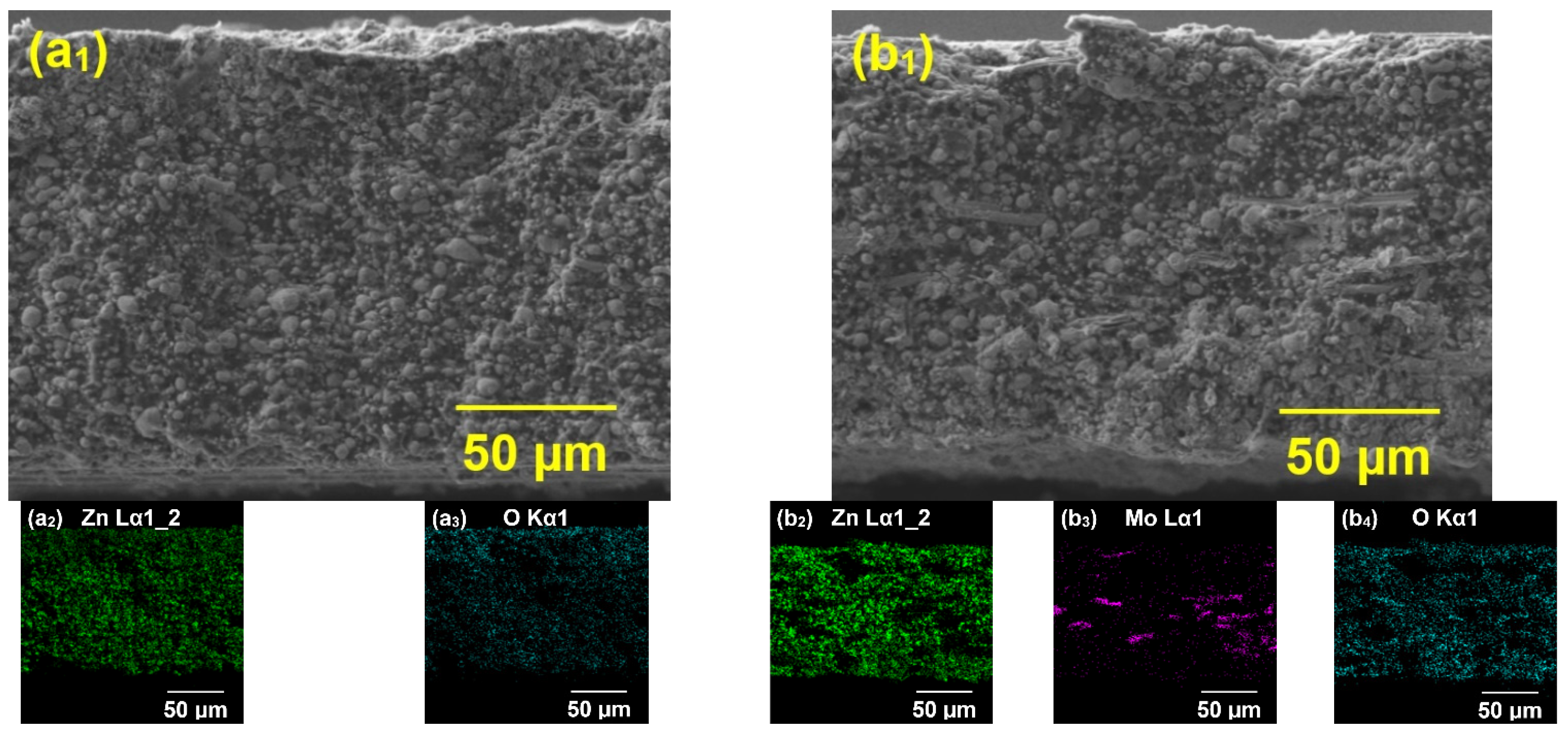
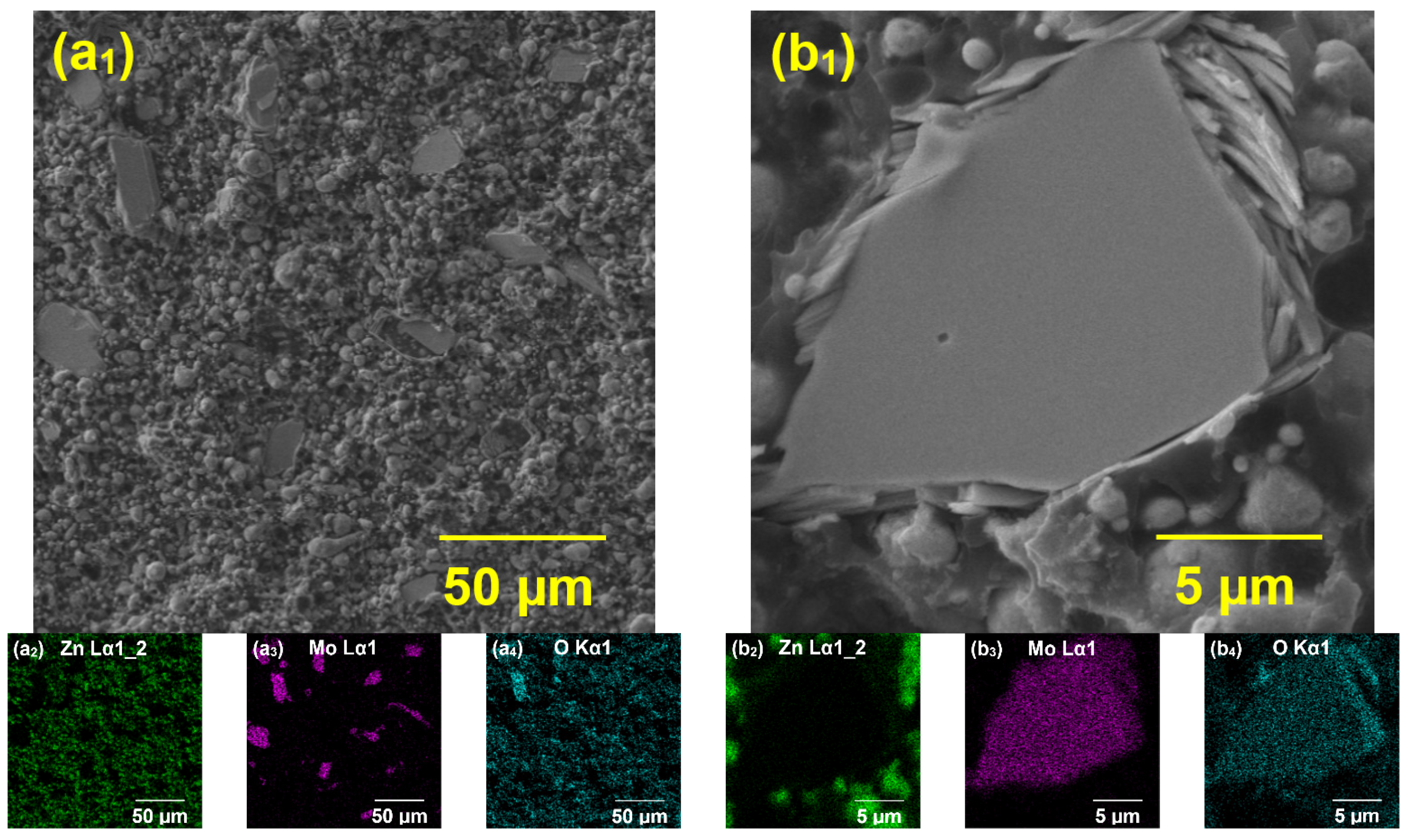
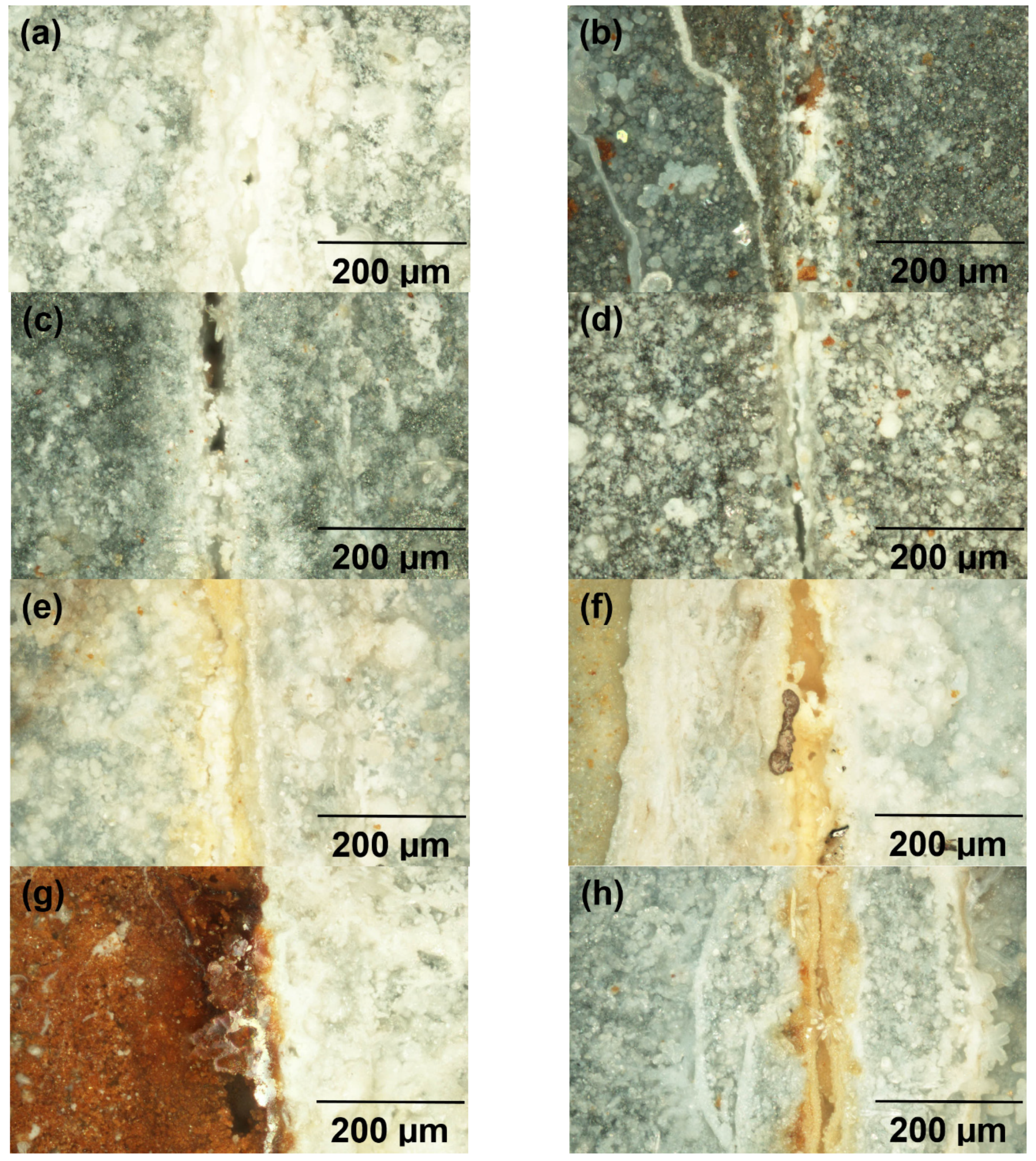
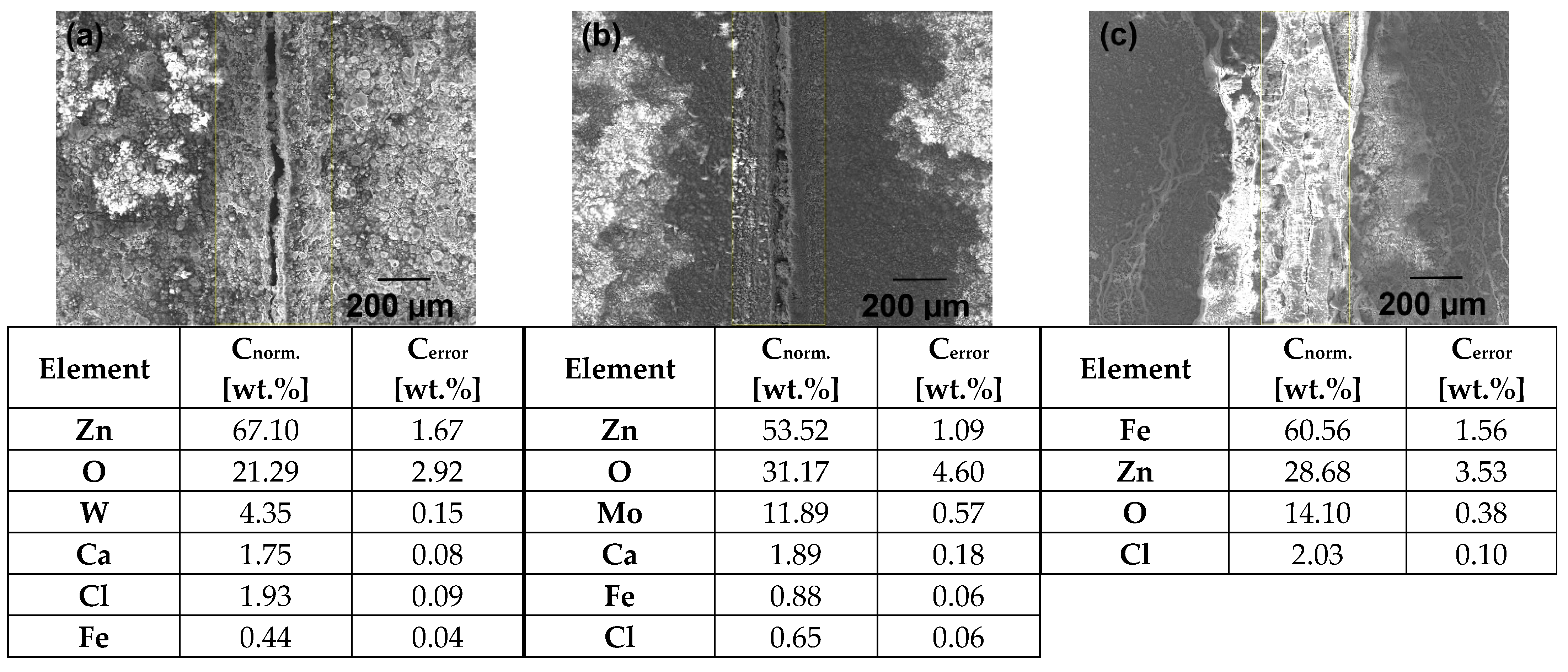
Electron Microanalysis Studied Organic Coatings

The investigated organic coatings were subjected to electron microanalysis using a TESCAN VEGA 5130SB scanning electron microscope (Tescan, Brno, Czech Republic) and a Bruker Quantax 200 energy dispersive X-ray spectrometer (Bruker, Billerica, Massachusetts, USA) to determine the elemental composition of the organic coatings containing the studied organic and inorganic pigments after 960 h of exposure in atmosphere salt electrolyte.

3.5. Electrochemical Measurement Linear Polarization

The polarization curves of the investigated organic coatings were measured using a multichannel potentiostat/galvanostat VSP-300 (Bio-Logic, Seyssinet-Pariset, Grenoble, France). The polarization curves were evaluated using the 2012 version of EC-Lab® software, version V10.23. In a galvanic cell (Bio-Logic, Seyssinet-Pariset, Grenoble, France) with a platinum working electrode and a saturated calomel electrode, the samples were subjected to a 1 M NaCl solution. One centimeter square of each distinct organic coating under study was polarized at a rate of 0.166 mV·s−1 over the range of −10 mV EOC−1 to +10 mV EOC−1.

3.6. Determination of pH and Specific Electrical Conductivity and Corrosion Loss from Aqueous Extracts of Pigments and Paint Films

In order to ascertain pH and specific electrical conductivity (λ) from aqueous pigment extracts, 10% pigment suspensions in redistilled water were made, along with a loose paint layer. The paint was applied to polyethylene foils and then removed after 60 days to create the loose paint films. The films of loose paint were sliced into 1 mm by 1 mm pieces. Over the course of 28 days, the pH and specific electrical conductivity of the produced suspensions were measured. A pH meter (WTW 320, Labexchange-Die Laborgerätebörse GmbH, Burladingen, Germany) was used to measure pH in accordance with the protocol adopted from ISO 787-9 [71]. Prior to the determination, the pH meter was calibrated using buffer solutions with known pH values at the temperature of the test. A conductometer (Handylab LF1, Schott-Geräte GmbH, Landshut, Germany) was used to measure specific electrical conductivity in accordance with the methodology developed from ISO 787-14 [72]. Prior to the determination, the conductometer was calibrated using standard calibration solutions with known electrical conductivity values at the test temperature. Following a 28-day period, both varieties of suspensions underwent filtering. The filtrates were then used to ascertain the corrosion losses subsequent to the cleaning, weighing, and immersion in aqueous extracts of steel panels (40 mm × 20 mm × 1 mm) with precision inside ±0.0001 g using an analytical balance. After five days, the steel panels were taken out of the filtrates, freed from corrosion products (a 20% HCl aqueous solution with 0.5 wt.% urotropine added), dried, and weighed once more. This allowed for the completion of the corrosion loss calculation. The mass data were utilized to determine the corresponding corrosion-related losses (Km). The weight percentages (XH) associated with the weight loss of steel in distilled water were used to express the losses. These findings were used to compute the weight losses of steel (VK) and the loss of steel panel dimensions (UR).

4. Results and Discussion

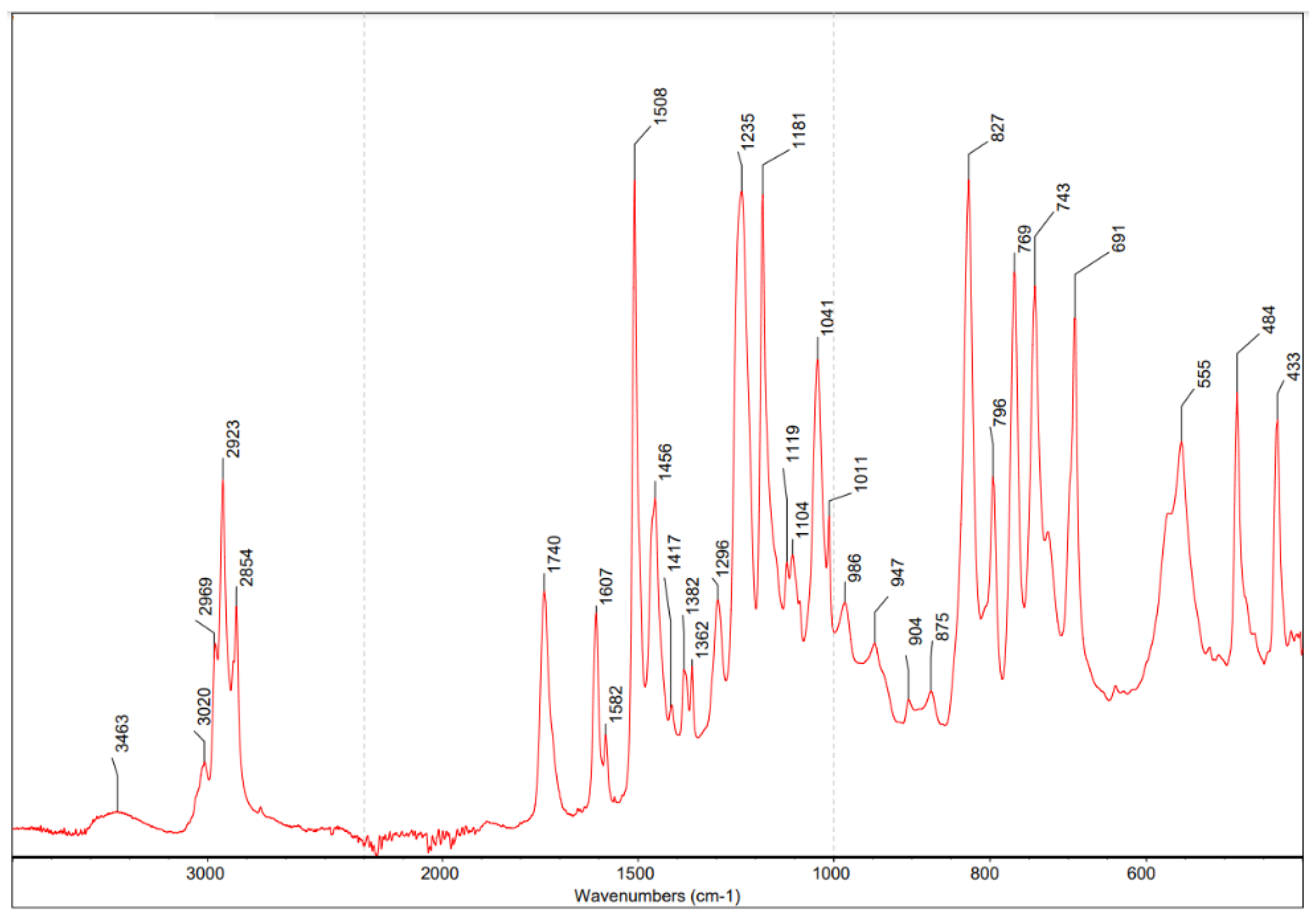
4.1. Specification of the Used Binder

Binder specification is summarized in Table 1. The acid value is a number used to quantify the acidity of a given chemical substance, and for epoxy ester resin, it reached the value of 3.9 mg KOH·g−1. This parameter provides information about the quantity of base (potassium hydroxide), expressed as milligrams of KOH required to neutralize the acidic constituents in 1 g of a sample. The viscosity of the system is a measure of its resistance to deformation at a given rate, and for a given type of resin, it reached the value of 4200 mPa·s−1, with measurement parameters of 23 °C, C 60/2, and 50 s. The color of the binder was determined based on the Gardner color scale using a color-measuring instrument. This procedure is commonly used for resins. The color of the given resin reached a value of 10. The resin forms corresponding to 60% in xylene were determined using dry matter determination. The spectrum of the epoxy ester resin shown in Figure 1 was measured. In the given spectrum, a wide band of valence vibration of OH groups (hydroperoxides, alcohols, carboxyl groups) was found at 3590–3280 cm−1. In the region 3000–2809 cm−1, bands of CH vibrations of aliphatic fatty acid chains were found. Moderately intense bands at 1740 and 1235 cm−1 are typical for the presence of ester groups (valence vibrations C=O and C-O). The intense band at 1181 cm−1 is due to the presence of ether bonds. This type of commercial binder is excellent for quick-drying primers and top coats and has very good adhesion and chemical resistance. This type of binder is recommended by the manufacturer for the preparation of highly pigmented zinc anti-corrosion coatings [73].

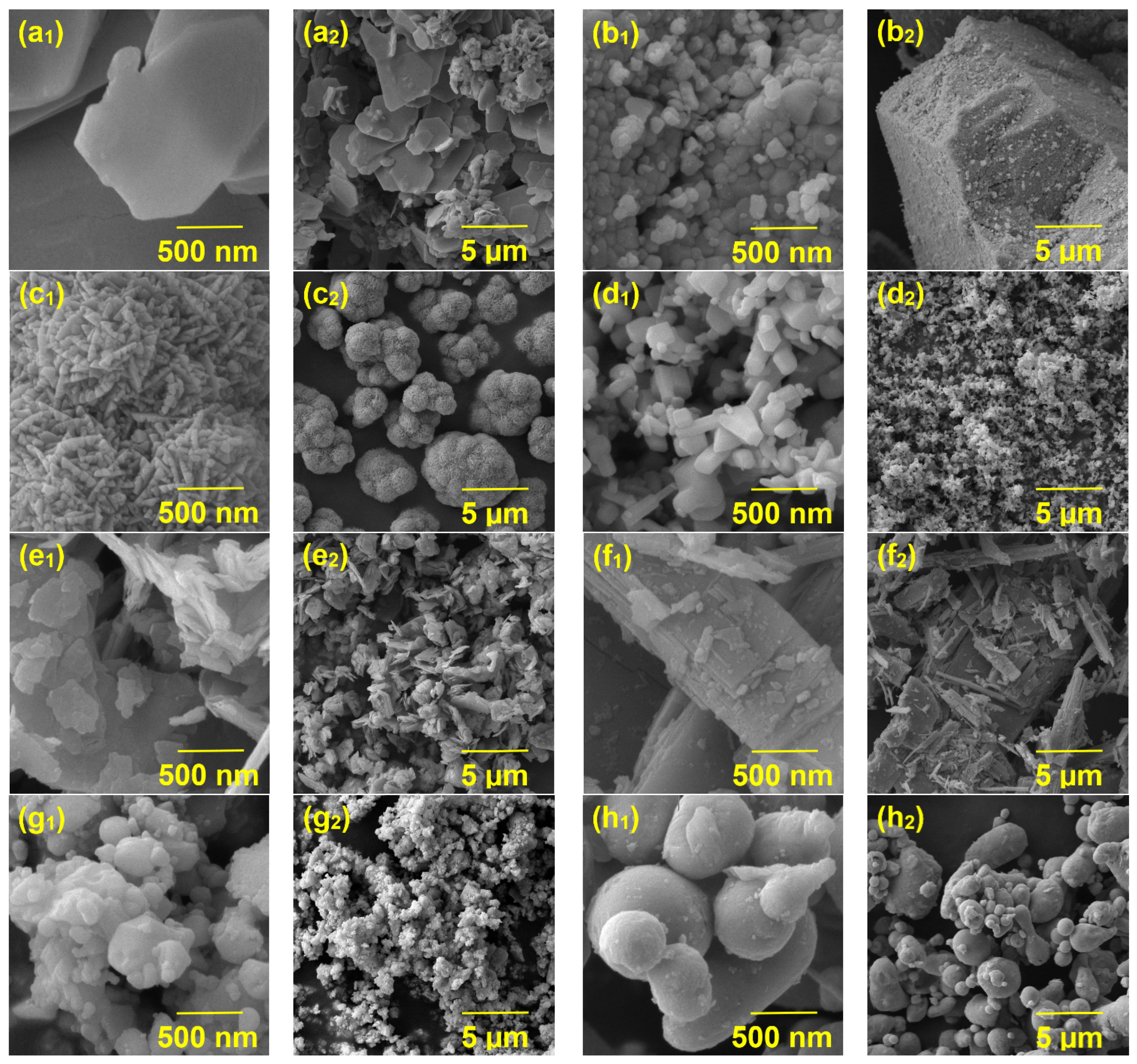
4.2. Characterization of the Studied Inorganic Pigments

The eight types of studied inorganic pigments were subjected to measurements of the typical paint parameters, i.e., density and oil number, which are used to calculate the critical pigment volume concentration (CPVC) of each pigment. The results of the pigments studied are summarized in Table 2. The densities of the studied inorganic pigments ranged from 4.05 g·cm−3 (zinc sulfide) to 7.27 g·cm−3 (tungsten oxide), while the density of zinc reached the second highest value of 7.14 g·cm−3. The lowest oil absorption value (6.7 g/100 g) was determined for metallic zinc dust, while the highest oil absorption value (30.7 g/100 g) was determined for molybdenum sulfide. The oil absorption values of other types of inorganic pigments ranged from 11.2 (tungsten oxide) to 19.4 (tungsten sulfide). The oil absorption parameter is significantly dependent on the surface area of the studied particles and, thus, on the particle size [74], which was studied for individual types of inorganic pigments on the basis of micro-photographs taken by scanning electron microscopy (SEM). On the basis of the above-mentioned parameters (density and oil absorption), the CPVC parameter was calculated for individual types of inorganic pigments. The highest value of this parameter (66.0) was achieved specifically with metallic powdered zinc, while the lowest value of CPVC (39.3) was recorded with molybdenum sulfide pigment due to the high oil absorption recorded for this type of inorganic pigment.
The representative SEM scans of studied inorganic pigments with different magnifications are shown in Figure 2. The measured SEM scans revealed that WS2 (a), MoS2 (e), and MoO3 (f) exhibited sheet-like structures. WS2 particles were bigger (2–5 µm in diameter) with predominantly hexagonal shape. MoS2 and MoO3 particles possessed a typical layered structure. The WO3 sample (b) contained small spherical particles (100–200 nm) bonded into big agglomerates (up to 20 µm in diameter). The ZnS (c) formed polycrystalline spherical clusters with tetrahedral shape of primary nanoparticles (50–100 nm). The ZnO (d) particles had oval to rectangular shapes and size distributions between 100 and 500 nm. The sample of ZnS/BaSO4 (g) contained a variety of strongly bonded oval or spherical particles forming 0.5–1 µm agglomerates. The metallic Zn (h) particles possessed a predominantly spherical shape with 0.5–5 µm in diameter.

The Results of the EDX Analysis of the Studied

Pigments are summarized in Table 3. The data show that the measured composition is close to the expected one. The oxygen content in WS2 and ZnS confirms their tendency to minor hydrolysis, while MoS2 remains stable. The Zn particles also contain a thin film of ZnO. As WO3 occurs naturally as a hydrate, the oxygen content is also slightly elevated.

4.3. Results of Mechanical Properties of the Protective Coatings

The mechanical properties of the studied organic coatings containing the different types of tested inorganic pigments (with DFT = 60 ± 5 µm) were studied after the relative surface hardness values of the coating films were reached. This settling was recorded after 60 days of conditioning the samples in a climate-controlled room under conditions where the temperature was 22 ± 1 °C, and the humidity was 50% ± 1% throughout. After 60 days, the standard organic coating pigmented with zinc alone reached a relative surface hardness value of 37.2%, which did not change over time, whereas the relative surface hardness of the unpigmented organic coating reached a relative surface hardness value of only 33.1% at day 60. The values of the relative surface hardness of the organic coatings studied containing the different types of pigments tested were between these two values and did not change with time after 60 days. The lowest relative surface hardness values after 60 days of these organic coatings were achieved by systems containing the pigment MoO3, while the highest relative surface hardness values were achieved by systems containing the pigment WS2. The only exception was organic coatings containing ZnS pigment, where these coatings reached the highest values of relative surface hardness after 60 days compared to other types of organic coatings. They were the only ones to achieve relative surface hardness values even about 2% higher after 60 days compared to standard zinc-pigmented organic coatings, despite the fact that the individual systems were pigmented to a constant solids ratio.
The studied organic coatings containing inorganic pigments were subjected to individual empirical test procedures derived from relevant standards in order to evaluate the resistance of the studied coatings to cracking and/or separation from the metal substrate. Based on the results of the four types of commonly used standardized tests, it was not possible to distinguish the mechanical resistance of the organic coatings studied, as all organic coatings achieved comparable and maximum mechanical resistance. When studying the degree of adhesion on the steel substrate, the organic coatings studied achieved an adhesion degree of 0, where the individual cuts were completely smooth even where they crossed. This standardized test was also the only one performed to study the mechanical resistance of the studied organic coatings applied on glass panels after the relative surface hardness determination was completed, i.e., after 90 days. The adhesion of the individual organic coatings studied on the glass substrates reached an adhesion grade of 1 for the standard organic coating and for the other organic coatings evaluated, where the individual cuts were completely smooth, but there was slight damage at the cut crossing points, but not exceeding 5% of the area evaluated. The only exceptions were the organic coatings pigmented with WS2 and MoS2 at all studied PVC, where these coatings achieved an adhesion grade of 0 when evaluated on glass substrates. This fact can be explained by the reinforcing ability of these types of pigments caused by the lamellar layered structure, which had a positive impact on the mechanical resistance of the studied coatings. All types of the studied organic coatings applied on the steel panels achieved comparable resistance even in the bending test over a cylindrical mandrel, where no damage occurred even when bending over a 4 mm diameter cylindrical mandrel. Damage was also not observed in any organic coatings studied after a drop of a kilogram weight from a height of 1 m, either in the reverse or the face test. No cracking or separation of the organic coatings was observed during the excavation test, which was carried out at a distance of 10 mm for each coating. After the pull-off test, it was possible to distinguish the mechanical resistance of the organic coatings studied. The standard organic coating pigmented only with zinc achieved a pull-off strength of 2.17 MPa. The organic coatings containing WO3, ZnO, ZnS, and MoS2 pigments achieved higher values of pull-off strength (2.6–2.9 MPa) at the studied PVC values, while the organic coatings containing ZnS/BaSO4 pigment achieved comparable values of pull-off strength compared to the organic coating pigmented with zinc only. The highest values of pull-off strength were achieved by organic coatings containing WS2 and MoO3 pigments, where the pull-off strength reached values higher than 3 MPa. For all organic coatings evaluated, a cohesive fracture type was observed in the layer of the organic coatings studied exceeding 90% of the evaluated area, where, in most cases, this fracture type was observed in 100% of the evaluated area. This type of fracture is typical for zinc-pigmented systems as they are systems with a high content of pigment particles. After the pull-off test and the evaluation of the fracture type, the DFT was measured at the location where the pull-off test was performed, and it was clearly concluded from the results that the location with the lowest cohesiveness of the paint films with DFT = 60 ± 5 µm lies at DFT = 30 ± 5 µm, i.e., approximately only at ½ the thickness of the paint film. This conclusion was valid for all the coating film systems studied in this work.
The fact that the highest values of pull-off strengths were achieved for zinc-pigmented organic coatings containing MoO3 and WS2 can be explained from a physical point of view in two ways. Firstly, it is the reinforcing ability of the particles of this type of pigment due to its special lamellar layered particle structure and the ability of its particles to orient themselves in the coating after application in a parallel direction to the substrate, whereby the strength of the coating film was increased as a result of these facts. Furthermore, it has been shown in studies that this type of special 2D material has the ability to fill the natural pores present in the organic coating, resulting in an increase in the strength of the system as a whole [75,76]. Both of the above physical aspects are confirmed by the fact that the values of the pull-off strengths increased with increasing PVC values of the individual 2D materials in the zinc-pigmented organic coatings and by the fact that the lowest pull-off strengths were achieved by the organic coating pigmented with spherical-type zinc without the presence of the 2D materials studied. These conclusions are confirmed by the microphotographs of transverse fractures of the selected organic coatings, shown in Figure 3, and the microphotographs of the surface of the coating film at the cohesive fracture point after the pull-off test, shown in Figure 4; these images reveal that it is a heterodisperse hybrid protective system consisting of both spherical type zinc particles and layered 2D MoO3 pigment particles. Moreover, it is evident from the microphotographs of this system that the 2D MoO3 pigment particles are uniformly dispersed and, in addition, oriented uniformly with the protected substrate in the system. The identification of the different types of particles in the transverse refraction was performed using the SEM/BSE technique (back-scattered electron technique scans with elemental contrast) and elemental mapping (Figure 3, Figure 4 and Figure 5). The results confirmed that the oriented 2D particles contained Mo and O, while spherical particles contained primarily Zn.

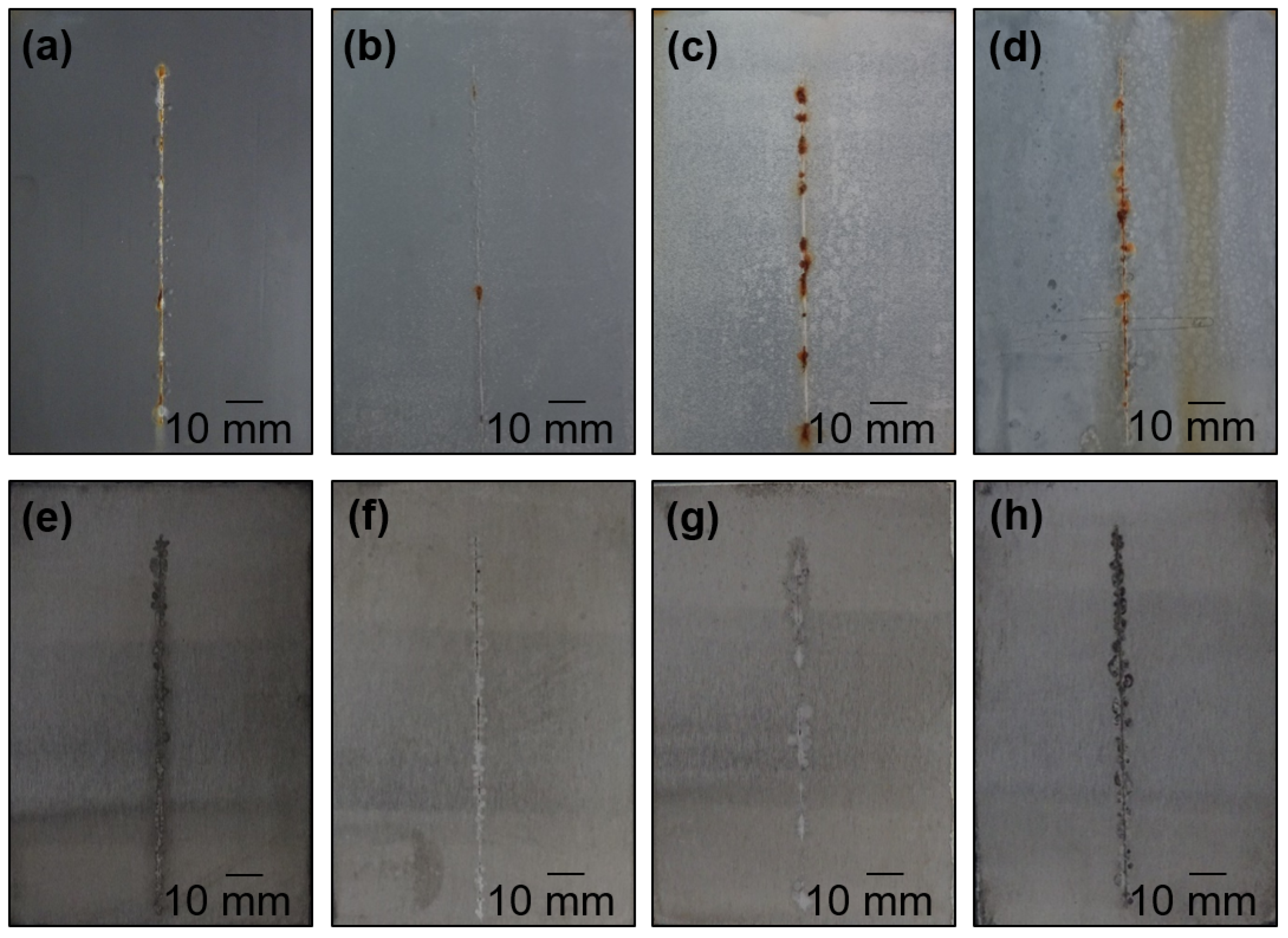
4.4. Anti-Corrosion Efficiency of Pigmented Epoxy Ester Coatings in an Atmosphere Containing Salt Electrolyte

The studied organic coatings with DFT = 90 ± 5 μm were exposed in a salt electrolyte atmosphere for 960 h. A photograph of the selected organic coating after 960 h of exposure in an atmosphere containing salt electrolyte and steel panels after removing the organic coatings is shown in Figure 6. During the exposure, the degree of blistering outside and in the area of the test section was evaluated, and after the exposure of each organic coating, the degree of adhesion was determined by a grid test. Subsequently, the organic coating was removed, and the corrosion manifestations on the steel panel were evaluated. The results of the individual parameters evaluated after 960 h exposure are shown in Table 4.
Based on the results of the individual organic coatings studied after 480 h of exposure in this type of corrosive atmosphere, it can be stated that none of the organic coatings studied showed blistering in the coating film area. Even for the systems containing MoS2 or MoO3 pigment, no blistering or red rust was observed in the vicinity of the test section, whereas for the other organic coatings, blistering was observed in the vicinity of the test section after 480 h exposure in the range of 8F to 6M, as well as the presence of red rust in the vicinity of the test section. No corrosion of the coating film and the presence of red rust in the area of the coating film were noted for any of the organic coatings tested after 480 h of exposure. The appearance of red rust in the vicinity of the test section was noted after 240 h of exposure of the sample to this corrosive atmosphere; for organic coatings pigmented with MoS2 or MoO3, the appearance of blistering in the cut was observed after 720 h of exposure, except for the organic coating containing MoO3 at PVC = 10%, where no blistering in the cut was observed even after the end of exposure (960 h of exposure). The corrosion of the paint film and the occurrence of red rust in the paint film area after 960 h of exposure were observed only for the WO3-pigmented paint film at all three PVC values when this parameter did not exceed 0.1% of the area. The degree of adhesion of all organic coatings before exposure was 0. Only the organic coatings pigmented with MoS2 and MoO3 reached the same degree of adhesion after 960 h exposure in this type of corrosive environment at PVC = 5% and 10%, while the standard organic coating pigmented with zinc only reached a degree of adhesion of 1 after this exposure. The decrease in the degree of adhesion of the standard organic coating was mainly due to the formation of blisters in the coating film area evaluated at grade 8F.
From the above results, it is evident that the highest anti-corrosive efficiency was achieved by organic coatings pigmented with MoS2 or MoO3, where the appearance of red rust was observed in the test section of the MoS2 pigmented coatings after this exposure, while the test section of the MoO3 pigmented coating is completely free of red rust. Even after 960 h exposure, no blistering was observed in the test section of the organic coating of pigmented MoO3 at PVC = 10%. The high anti-corrosive efficiency of the organic coatings pigmented with MoS2 and especially then MoO3 was ensured due to the rapid homogeneous sealing of the test section by corrosive zinc fumes as a result of the electrochemical mechanism of the zinc-pigmented coating film enhanced by the presence of one of these two types of pigments. This is documented in the microphotographs shown in Figure 7, where the healing of the test section of each coating can be seen. In addition, for systems pigmented with MoS2 or MoO3, no blistering was observed in the coating film area after 960 h of exposure of the samples to a salt electrolyte atmosphere, whereas for all other types of systems studied, blistering was observed in the coating film area and ranged from 8F to 6M. This conclusion can also be explained by the demonstrated ability of these types of 2D materials to fill the natural pores present in organic coatings as well as to fill the diffusion channels present in organic coatings and block the passages from corrosive medium penetration [75,76].
The surface of the studied organic coatings after the completion of this cyclic corrosion test (i.e., after 960 h of exposure) was studied using the SEM-EDX technique both in the test section and in the organic coating area. Micrographs, including the composition of selected organic coatings outside the test section area, are shown in Figure 8. When studying the surfaces of the coating films outside the test cut area, none of the coatings studied by this technique were identified as having ferrous compounds (corrosive iron fumes) that would demonstrate imperfect protection of the protected steel substrate. For all coatings in the area outside the test section, a protective layer was formed, ensuring long-term corrosion protection even in environments where corrosion initiators in the form of chloride ions are present. Detailed microphotographs of one of the organic coatings studied are shown in Figure 9, wherein the microphotographs, not only at the highest magnification, it is possible to distinguish both the corrosion products of zinc (mainly ZnO) and the presence of WO3 particles, whose presence was also confirmed by the X-ray analysis.
Micrographs, including the composition of selected organic coatings in the test section area, are shown in Figure 10. When studying the areas of each test section, the presence of ferrous compounds (corrosive iron fumes) was identified in all of the coatings studied by this technique, where, specifically, the organic coating containing MoO3, MoS2, and WO3 at PVC = 10% had an iron corrosive fume content of <1 wt.%. The corrosion products of zinc and the oxide or sulfide of the respective metal were the dominant components in the test section for these coatings, whereas, for the standard organic coating, the iron corrosion products were the dominant component, and their content exceeded 60 wt.%. This fact is also evident from the microphotographs, where the test section of the standard organic coating is filled mainly with bulky iron corrosion products together with zinc corrosion products. These corrosion fumes completely fill the section, where their lack of corrosion protection and bulkiness leads to cracking of this layer (as can be seen from the microphotographs) and penetration of the corrosive environment to the substrate and its further corrosion, manifested mainly by the increasing volume of corrosion fumes. From the microphotographs of the system containing WO3 or MoO3, it is evident that the test cut was sealed with corrosion products and prevented the penetration of the corrosive environment to the protected steel substrate almost perfectly, as evidenced by the results of the SEM-EDX analysis technique.
To confirm the above conclusions, after the cyclic corrosion test, samples of corrosion products were collected from each section and analyzed by powder X-ray diffraction (XRD) analysis to determine the exact composition of the corrosion products. Based on these results, it can be concluded that all samples were analyzed for the presence of zinc corrosion products in the test sections, specifically ZnO and Zn5(OH)8Cl2·H2O, which are typical types of zinc corrosion products formed when zinc-pigmented coatings are exposed to NaCl containing environments, along with Zn5(CO3)2(OH)6 and Zn(OH)2 [77]. For zinc-pigmented organic coatings containing MoO3, X-ray diffraction analysis showed the presence of MoO3 in addition to zinc corrosion products in a sample taken from a test section. Identified zinc corrosion products, specifically ZnO and Zn5(OH)8Cl2·H2O, arising as a result of the electrochemical mechanism of zinc action, ensure the protection of the test cut by a barrier mechanism. The individual diffraction patterns are shown in Figure 11.

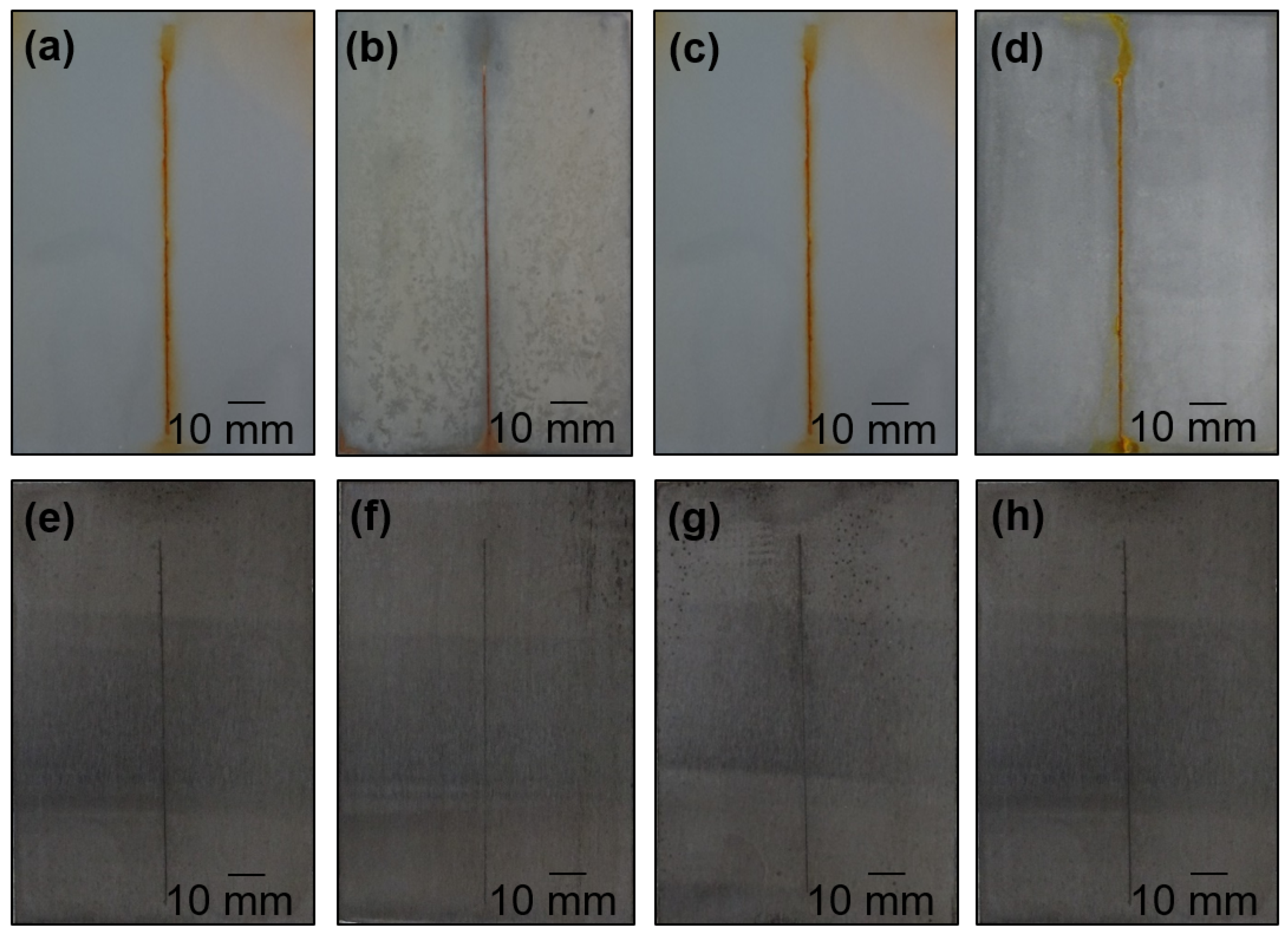
4.5. Anti-Corrosion Efficiency of Pigmented Epoxy Ester Coatings in an Atmosphere Containing SO2

The studied organic coatings with DFT = 90 ± 5 μm were exposed in an atmosphere containing SO2 for 960 h. A photograph of the selected organic coating after 960 h of exposure in an atmosphere containing SO2 and steel panels after removing the organic coatings is shown in Figure 12. During the exposure, the degree of blistering outside and in the area of the test section was evaluated, and after the exposure of each organic coating, the degree of adhesion was determined by a grid test. Subsequently, the organic coating was removed, and the corrosion manifestations on the steel panel were evaluated. The results of the individual parameters evaluated after 960 h exposure are shown in Table 5.
On the basis of the results of individual studied organic coatings in this type of corrosive atmosphere, it can be stated that after 480 h of exposure, the occurrence of blistering in the area of organic coatings containing the pigments MoO3, MoS2, and WO3 was not recorded at all studied PVC values, while for other organic coatings, the degree of blistering in the area of the coating reached 8F-8D. For organic coatings with WO3, pigment content at PVC = 5% and 10%, and coatings with MoS2 and MoO3, pigment content at all studied PVC values, no blistering was observed in the coating film area or in the test section. For the other organic coatings, blistering was observed in the coating area at grade 8F or 8M after 960 h exposure. In addition, no corrosion of the coating film (the appearance of red rust on the surface of the coating film) was observed in any of the organic coatings tested after 960 h of exposure. For the standard organic coating, the adhesion reached grade 2 after 960 h of exposure, while for the organic coatings containing MoO3 and MoS2 pigments, the adhesion reached grade 0 after this exposure, where the same degree of adhesion was achieved by these coatings before exposure of the systems in this type of corrosive environment.
Sulfur dioxide, to which, together with water vapor, the organic coatings studied in this cyclic test were exposed, is classified as a substance generally referred to as a corrosion stimulant, where, specifically for SO2, the rate of corrosion of zinc is proportional to the concentration of this corrosion stimulant in the air. When zinc-pigmented systems are exposed to SO2-containing atmospheres, the oxidation of SO2 leads to the formation of sulfate ions (SO42−), which lower the pH locally, resulting in an increase in the rate of zinc corrosion. The corrosion in this type of corrosive atmosphere is influenced mainly by temperature (in which case, it is an inversely proportional relationship), which affects the type of corrosion products produced, which vary in solubility. In SO2-containing atmospheres at higher temperatures, primarily insoluble zinc hydroxy sulfate (Zn4SO4(OH)6·H2O) is formed, which slows down the action of SO2 compared to other types of corrosive fumes, e.g., typical zinc sulfate (ZnSO4·H2O), which is soluble and, consequently, less affected by SO2 [77,78].
From the above results, it is evident that the highest anti-corrosive efficiency was achieved by organic coatings pigmented with MoO3, where this fact can be explained mainly by the ability of MoO3 to react with oxides to form molybdenates (e.g., H4[Mo(SO4)O4] hydrogen tetraoxosulfatomolybdate), or other types of oxides (e.g., Mo2O5), which are very stable compounds, and their solubility is very low, resulting in the formation of a protective passivation layer with a barrier character which protects the zinc pigmented system from further dissolution caused by its reaction with SO2. In addition, MoO3 itself is referred to in the literature as a special type of oxide with the character of a passivation layer, which has the ability to protect its surroundings from the action of acidic solutions [79,80]. This conclusion is confirmed by the fact that for organic coating with this type of pigment (MoO3) at the highest PVC = 10%, the smallest change in the dry thickness of the coating film was observed after 960 h of exposure in this type of corrosive atmosphere. While the standard organic coating pigmented only with zinc showed a decrease in DFT of 10 ± 2.5 µm, the organic coating containing MoO3 pigment (at PVC = 10%) showed a decrease in DFT of only 5 ± 2.5 µm.
Similar anti-corrosive performance was achieved by zinc-pigmented systems containing MoS2, where the literature describes that MoS2 is insoluble in an atmosphere containing SO2 and condensed moisture or when exposed to sulfuric acid, up to pH = 2 [81], where the organic coatings studied in this cyclic corrosion test are not exposed to such low pH values. In view of this fact, it can be concluded that this type of pigment in the zinc-pigmented coating film also provides primary barrier protection, which, due to its nature, protects the zinc-pigmented system and, thus, enhances its anti-corrosion capabilities.

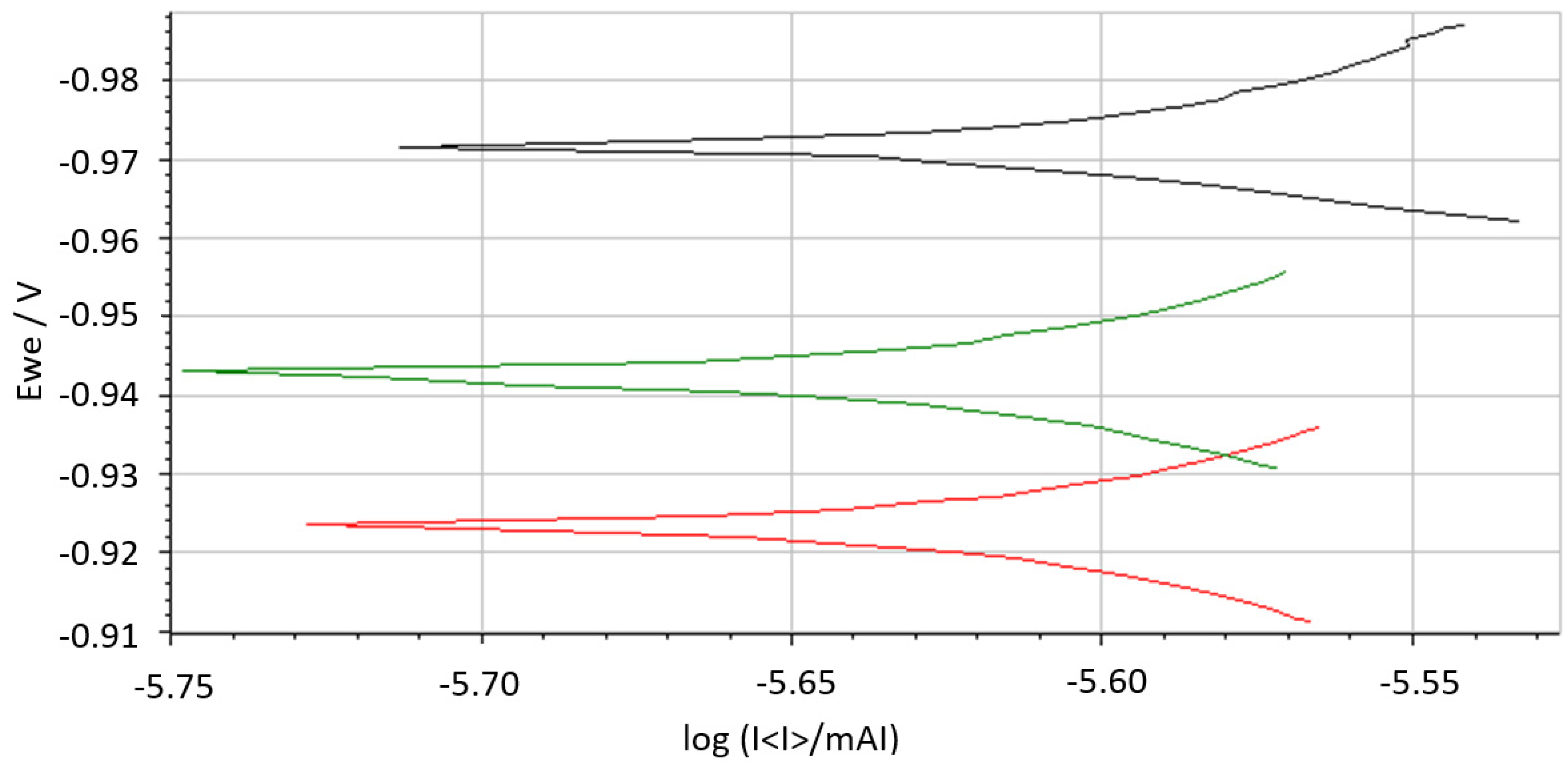
4.6. Study of Anti-Corrosion Properties of Organic Coatings Using the Linear Polarization

The studied organic coatings were subjected to the electrochemical technique of linear polarization to measure the individual polarization curves, which represent the relationship between corrosion potential and corrosion current density, which were subsequently analyzed in order to determine the parameters (corrosion potential (Ecorr), corrosion current (Icorr), Tafel slopes (βa and βc)) that provide information on the anti-corrosion performance of the organic coatings [82,83,84,85,86]. The results of this technique are shown in Table 6. Figure 13 shows tafel plots of selected organic coatings containing the studied pigments, which are discussed below. In the electrochemical linear polarization test, the studied organic coatings were exposed to a 1M NaCl solution in a Galvanic cell prior to the actual measurement of the polarization curves, where a sample of the coating film applied on a steel panel was connected as a working electrode in combination with a saturated calomel electrode and a platinum electrode, and the polarization curves were measured after the spontaneous corrosion potentials had stabilized.
The results show that the spontaneous corrosion potentials of the studied organic coatings after their stabilization reached values in the interval from −923 to −971 mV. The value of spontaneous corrosion potentials of the standard zinc-pigmented organic coating reached a value of −980 mV. For organic coatings pigmented with MoS2 and MoO3, the lowest corrosion current values were recorded, ranging from 2.82 × 10⁻⁶ to 1.74 × 10⁻⁶ µA. For these organic coatings, the highest values of polarization resistance ranging from 2.17 × 10⁹ to 3.63 × 10⁹ Ω were also recorded, which were one order of magnitude higher compared to the other types of organic coatings studied, except for the organic coatings containing WO3 pigment. For organic coatings containing MoO3, a trend was noted that with increasing PVC value, the value of polarization resistance gradually increased, while the value of corrosion rate decreased due to the presence of these pigment particles. These organic coatings with the highest values of polarization resistances were also found to have the lowest values of corrosion rates compared to the other studied coatings, including the standard organic coating pigmented only with spherical zinc. The highest value of polarisation resistance of all the organic coatings studied was recorded for the organic coating containing MoO3 pigment at PVC = 10%, where the lowest value of corrosion rate was also recorded for this coating. The conclusions presented on the basis of the analysis of the polarization curves are in full agreement with the results of the cyclic corrosion test when the studied organic coatings were exposed to a mist of electrolyte consisting of NaCl and (NH4)2SO4 solution.

4.7. Determination of pH and Specific Electrical Conductivity and Corrosion Loss from Aqueous Extracts of Loose Paint Films

The prepared free coating films of each coating film were used to prepare 10% aqueous suspensions using distilled water with pH = 6.98 and conductivity of 1.5 µS·cm−1. The pH and conductivity of each system were measured as a function of time, with Table 7 showing the results determined after 24 h and 28 days. From the results of studying the change in pH, it can be concluded that only the system containing MoO3 pigment showed a slight decrease in pH to 6.7, while the other systems showed almost no change in pH. The results of conductivity measurements show that for the systems containing MoS2 and ZnS/BaSO4 pigments, there was an increase in conductivity of one order of magnitude, whereas, for the systems containing MoO3 pigment (at all PVC values studied), there was an increase in conductivity of two orders of magnitude. Specifically, the system containing MoO3 at PVC = 10% achieved a conductivity value of 1309 µS·cm−1, while the system containing zinc achieved a conductivity of 57 µS·cm−1. The increase in conductivity for the systems containing MoO3 pigment can be explained by the formation of molybdic acid, which was also reflected by a decrease in the pH value of the aqueous leachate. This conclusion is supported by the fact that MoO3 is only sparingly soluble in water and is also classified as an acid-forming oxide, which is its ability to react with water to form the corresponding types of acids [87]. The presence of molybdic acid in the aqueous leachate is further confirmed by the fact that the pH of the aqueous leachate of the MoO3 pigment reached pH = 2.91 after 28 days. The filtrates of each system were used to determine the weight loss of the embedded steel panels. The lowest mass losses (KMf) were recorded for the aqueous leachates of the systems containing MoO3 pigment. In the filtrate after systems containing this pigment at PVC = 10%, the lowest weight loss of the steel panel was clearly achieved, with a KMf of 0.09 g·m−2, while this parameter reached 0.45 g·m−2 in the aqueous leachate after filtering out the standard organic coating pigmented only with zinc. The lowest corrosion loss in the aqueous filtrate after the MoO3 pigmented system at PVC = 10% can be explained by the presence of molybdic acid in the aqueous filtrate and the subsequent formation of molybdate salts, where molybdic acid anion acted as a corrosion inhibitor during the corrosion loss determination.

5. Conclusions

In this study, the effect of pigments of different types, natures, and sizes, namely, MoS2, WS2, MoO3, WO3, ZnS, and ZnO, on the mechanical and corrosion resistance of zinc-pigmented systems was studied. The 2D materials with ultrathin structures are characterized by water impermeability, high specific surface area, and excellent mechanical properties, which predestine them for wide application, not only in the field of corrosion protection of metallic materials. Another advantage that gives these types of 2D materials their anti-corrosion capabilities is their special lamellar structure. The properties of the inorganic layered materials and their compatibility with the coating system binders were tested in a solvent-type epoxy ester resin to investigate the effect of their concentration and different particle sizes on the physical, mechanical, and corrosion resistance of the studied systems. Pigments from the group of transition metal oxides and dichalcogenides were also characterized by a number of analytical methods. For this study, model coatings based on epoxy resin and the studied pigments at PVC = 3, 5, and 10% and supplemented with metallic spherical zinc at PVC/CPVC = 0.6 were formulated, prepared, and tested using a series of standard accelerated cyclic corrosion tests and also by the electrochemical technique of linear polarization. The results of these experimental techniques have shown an increase in both mechanical and corrosion performances when using these special types of inorganic pigments. In particular, the use of the MoO3 pigment resulted in a significant increase in both the anti-corrosive effectiveness and mechanical resistance of the zinc-pigmented organic coating due to the presence of this type of pigment in a given formulation of the model coating. This type of pigment in a given coating contributed to the enhancement of mechanical resistance mainly due to its morphology and layered structure, demonstrated by SEM images, providing reinforcing ability. The authors explain the increase in anti-corrosion performance by the formation of a heterostructural hybrid zinc-pigmented system in which this type of pigment, due to its morphology and character, reinforced the different types of mechanisms applied in the zinc-pigmented coating. In addition, the increase in corrosion performance is achieved due to the formation of molybdenum salts, which act as corrosion inhibitors, as demonstrated by the results of indirect corrosion tests carried out, specifically, the results of weight loss in the extracts of the respective types of free coating films. In addition, the ability of particles of this type of pigment to actively fill natural pores in organic coatings and, thus, increase both the mechanical resistance and anti-corrosion ability of these protective systems, as well as the ability of these substances to interact with a specific type of corrosive environment and create special types of corrosion products, which, as a result of the formation of a highly resistant passivation layer, creates barrier protection of the systems due to its inertness to the type of corrosive environment.

Author Contributions

Conceptualization, M.K. and A.K.; methodology, M.K.; software, M.K.; validation, M.K., S.S. and E.S.; formal analysis, M.K.; investigation, M.K., S.S. and E.S.; resources, M.K.; data curation, M.K., S.S., E.S. and K.B.; writing—original draft preparation, M.K. and K.B.; writing—review and editing, M.K.; visualization, M.K. and K.B.; supervision, M.K.; project administration, M.K.; funding acquisition, M.K. All authors have read and agreed to the published version of the manuscript.

Funding

The authors are thankful for financial support from the Ministry of Education, Youth and Sports of the Czech Republic (grant LM2023037).

Institutional Review Board Statement

Not applicable.

Informed Consent Statement

Not applicable.

Data Availability Statement

Data are contained within the article.

Conflicts of Interest

The authors declare no conflict of interest.

References

  1. Zhang, Y.; Su, J.; Xiao, X.; Wang, N.; Meng, G.; Gu, L. Graphene-like two-dimensional nanosheets-based anticorrosive coatings: A review. J. Mater. Sci. Technol. 2022, 129, 139–162. [Google Scholar] [CrossRef]
  2. Stejskal, J.; Trchová, M.; Brodinová, J.; Kalenda, P.; Fedorová, S.; Prokeš, J.; Zemek, J. Coating of zinc ferrite particles with a conducting polymer, polyaniline. J. Colloid Interface Sci. 2006, 298, 87–93. [Google Scholar] [CrossRef] [PubMed]
  3. Rostami, M.; Rasouli, S.; Ramezanzadeh, B.; Askari, A. Electrochemical investigation of the properties of Co doped ZnO nanoparticle as a corrosion inhibitive pigment for modifying corrosion resistance of the epoxy coating. Corros. Sci. 2014, 88, 387–399. [Google Scholar] [CrossRef]
  4. Nikravesh, B.; Ramezanzadeh, B.; Sarabi, A.A.; Kasiriha, S.M. Evaluation of the corrosion resistance of an epoxy-polyamide coating containing different ratios of micaceous iron oxide/Al pigments. Corros. Sci. 2011, 53, 1592–1603. [Google Scholar] [CrossRef]
  5. Kalendová, A.; Veselý, D.; Kohl, M.; Stejskal, J. Anticorrosion efficiency of zinc-filled epoxy coatings containing conducting polymers and pigments. Prog. Org. Coat. 2015, 78, 1–20. [Google Scholar] [CrossRef]
  6. Havlík, J.; Kalendová, A.; Veselý, D. Electrochemical, chemical and barrier action of zinc dust/anticorrosive pigments containing coatings. J. Phys. Chem. Solids 2007, 68, 1101–1105. [Google Scholar] [CrossRef]
  7. Hussain, A.K.; Seetharamaiah, N.; Pichumani, M.; Chakra, C.S. Research progress in organic zinc rich primer coatings for cathodic protection of metals—A comprehensive review. Prog. Org. Coat. 2021, 153, 106040. [Google Scholar] [CrossRef]
  8. Ahmadzadeh, M.; Shahrabi, T.; Izadi, M.; Mohammadi, I.; Hoseinieh, S.M.; Barnoush, A. Calcareous scales deposited in the organic coating defects during artificial seawater cathodic protection: Effect of zinc cations. J. Alloys Compd. 2019, 784, 744–755. [Google Scholar] [CrossRef]
  9. Feng, Y.; Wang, L.; Yang, Z.; Ma, Q.; He, D.; Xu, K.; Zhang, H.; Zhang, P.; Sun, W.; Liu, G. Effect of ZnO as corrosion product on corrosion behavior of zinc-iron corrosion protection systems. Corros. Sci. 2024, 227, 111802. [Google Scholar] [CrossRef]
  10. Ma, Q.; Wang, L.; Sun, W.; Yang, Z.; Wang, S.; Liu, G. Effect of chemical conversion induced by self-corrosion of zinc powders on enhancing corrosion protection performance of zinc-rich coatings. Corros. Sci. 2022, 194, 109942. [Google Scholar] [CrossRef]
  11. Arman, S.Y.; Ramezanzadeh, B.; Farghadani, S.; Mehdipour, M.; Rajabi, A. Application of the electrochemical noise to investigate the corrosion resistance of an epoxy zinc-rich coating loaded with lamellar aluminum and micaceous iron oxide particles. Corros. Sci. 2013, 77, 118–127. [Google Scholar] [CrossRef]
  12. Müller, B.; Oughourlian, C.; Schubert, M. Amphiphilic copolymers as corrosion inhibitors for zinc pigment. Corros. Sci. 2000, 42, 577–584. [Google Scholar] [CrossRef]
  13. Kalantar-zadeh, K.; Ou, J.Z.; Daeneke, T.; Mitchell, A.; Sasaki, T.; Fuhrer, M.S. Two dimensional and layered transition metal oxides. Appl. Mater. Today 2016, 5, 73–89. [Google Scholar] [CrossRef]
  14. Wert, S.; Iffelsberger, C.; Novčić, K.A.; Pumera, M. Corrosion of catalyst in high resolution: Layered transition metal dichalcogenides electrocatalyse water splitting and corrode during the process. J. Catal. 2022, 416, 85–91. [Google Scholar] [CrossRef]
  15. Sinha, A.; Dhanjai; Tan, B.; Huang, Y.; Thao, H.; Dang, X.; Chen, J.; Jain, R. MoS2 nanostructures for electrochemical sensing of multidisciplinary targets: A review. TrAC Trends Anal. Chem. 2018, 102, 75–90. [Google Scholar] [CrossRef]
  16. Naguib, M.; Gogotsi, Y. Synthesis of two-dimensional materials by selective extraction. Acc. Chem. Res. 2015, 48, 128–135. [Google Scholar] [CrossRef]
  17. Mas-Ballesté, R.; Gómez-Navarro, C.; Gómez-Herrero, J.; Zamora, F. 2D materials: To graphene and beyond. Nanoscale 2011, 3, 20–30. [Google Scholar] [CrossRef] [PubMed]
  18. Sadanandan, A.; Thomas, S.A.; Khan, M.E.; Alomar, M.S.; Pallavolu, M.R.; Cherusseri, J. A critical review on two-dimensional Ti3C2Tx MXenes for anti-corrosion coatings. Prog. Org. Coat. 2023, 183, 107757. [Google Scholar] [CrossRef]
  19. Xia, Z.; Liu, G.; Dong, Y.; Zhang, Y. Anticorrosive epoxy coatings based on polydopamine modified molybdenum disulfide. Prog. Org. Coat. 2019, 133, 154–160. [Google Scholar] [CrossRef]
  20. Lv, R.; Robinson, J.A.; Schaak, R.E.; Sun, D.; Sun, Y.; Mallouk, T.E.; Terrones, M. Transition Metal Dichalcogenides and Beyond: Synthesis, Properties, and Applications of Single- and Few-Layer Nanosheets. Acc. Chem. Res. 2015, 48, 56–64. [Google Scholar] [CrossRef]
  21. Joswig, J.O.; Lorenz, T.; Wendumu, T.B.; Gemming, S.; Seifert, G. Optics, Mechanics, and Energetics of Two-Dimensional MoS2 Nanostructures from a Theoretical Perspective. Acc. Chem. Res. 2015, 48, 48–55. [Google Scholar] [CrossRef]
  22. Eksik, O.; Gao, J.; Shojaee, S.A.; Thomas, A.; Chow, P.; Bartolucci, S.F.; Lucca, D.A.; Karotkar, N. Epoxy Nanocomposites with Two-Dimensional Transition Metal Dichalcogenide Additives. ACS Nano 2014, 8, 5282–5289. [Google Scholar] [CrossRef]
  23. Tan, W.; Zhao, W. Designing WS2@Ti3C2Tx heterojunction nanofillers via electrostatic self-assembly for achieving long term corrosion resistance under AHP environment. Mater. Today Nano 2022, 20, 100259. [Google Scholar] [CrossRef]
  24. Gnanaprakasam, P.; Mangalaraja, R.V.; Salvo, C. Microwave driven synthesis of tungsten sulfide nanosheets: An efficient electrocatalyst for oxygen reduction reaction. Mater. Sci. Semicond. Process. 2022, 137, 106213. [Google Scholar] [CrossRef]
  25. Rana, D.S.; Thakur, N.; Singh, D.; Sonia, P. Molybdenum and tungsten disulfide based nanocomposites as chemical sensor: A review. Mater. Proc. 2022, 62, 2755–2761. [Google Scholar] [CrossRef]
  26. Joseph, A.; Eapen, M.K.; Mampillly, M.E.; Sajith, V. Comparison of Corrosion Resistance Properties of Electrophoretically Deposited MoS2 and WS2 Nanosheets Coatings on Mild Steel. Metall. Mater. Trans. A 2021, 52, 3689–3693. [Google Scholar] [CrossRef]
  27. Hwnag, H.Y.; Isawa, Y.; Kawasaki, M.; Keimer, B.; Nagaosa, N.; Tokura, Y. Emergent phenomena at oxide interfaces. Nat. Mater. 2012, 11, 103–113. [Google Scholar] [CrossRef]
  28. Alsaif, M.; Balendhran, S.; Field, M.R.; Latham, K.; Wlodarski, W.; Ou, J.Z.; Kalantar-zadeh, K. Two dimensional α-MoO3 nanoflakes obtained using solvent-assisted grinding and sonication method: Application for H2 gas sensing. Sens. Actuators B Chem. 2014, 192, 196–204. [Google Scholar] [CrossRef]
  29. Scarminio, J.; Lourenço, A.; Gorenstein, A. Electrochromism and photochromism in amorphous molybdenum oxide films. Thin Solid Film. 1997, 302, 66–70. [Google Scholar] [CrossRef]
  30. Mutschall, D.; Holzner, K.; Obermeier, E. Sputtered molybdenum oxide thin films for NH3 detection. Sens. Actuators B 1996, 36, 320–324. [Google Scholar] [CrossRef]
  31. Razzaq, M.; Khan, M.J.; Imran, Z.; Ahmad, M.; Rasool, S.; Rehan, M.; Iqbal, S.; Anjum, M.A.R.; Mehboob, S.; Saifullah, M. Enhanced electrochemical performance of WO3 thin films prepared from polyvinyl alcohol-modified nanoparticle ink. Solid State Ion. 2023, 397, 116246. [Google Scholar] [CrossRef]
  32. Lee, S.H.; Cheong, P.L.; Smith, D.; Tracy, C.E.; Mascarenhas, A.; Pitts, J.R.; Deb, S.K. Raman spectroscopic studies of gasochromic a-WO3 thin films. Electrochim. Acta 2001, 46, 1995–1999. [Google Scholar] [CrossRef]
  33. Yin, X.-T.; Lv, P.; Li, J.; Jafari, A.; Wu, F.-Y.; Wang, Q.; Dastan, D.; Shi, Z.; Yu, S.; Germestani, H. Nanostructured tungsten trioxide prepared at various growth temperatures for sensing applications. J. Alloys Compd. 2020, 825, 154105. [Google Scholar] [CrossRef]
  34. KKapp, R. Molybdenum, Encyclopedia of Toxicology, 2nd ed.; Elsevier: Amsterdam, The Netherlands, 2005; pp. 145–148. ISBN 978-0-12-369400-3. [Google Scholar]
  35. Diaz-Algara, J.; Rendón-Angeles, J.C.; Matamoros-Veloza, Z.; Yanagisawa, K.; Rodriguez-Galicia, J.L.; Rivera-Cobo, J.M. Single-step synthesis of SrMoO4 particles from SrSO4 and their anti-corrosive activity. J. Alloys Compd. 2014, 607, 73–84. [Google Scholar] [CrossRef]
  36. Ingrid, M. Corrosion inhibition of aluminium alloys by molybdate ions: A critical review of the chemistry, mechanisms and applications. Corros. Sci. 2024, 229, 111854. [Google Scholar] [CrossRef]
  37. Brahim, E.I.; Abdelaziz, A.A.; Lei, G.; Savaş, K. Chapter 15—Molybdates as corrosion inhibitors. In Inorganic Anticorrosive Materials, Past, Present and Future Perspectives; Elsevier: Amsterdam, The Netherlands, 2022; pp. 297–321. [Google Scholar] [CrossRef]
  38. Jabeera, B.; Shibli, S.; Anirudhan, T. Synergistic inhibitive effect of tartarate and tungstate in preventing steel corrosion in aqueous media. Appl. Surf. Sci. 2006, 252, 3520–3524. [Google Scholar] [CrossRef]
  39. Li, Y.-Q.; Kang, Y.; Xiao, H.-M.; Mei, S.-G.; Zhang, G.-L.; Fu, S.Y. Preparation and characterization of transparent Al doped ZnO/epoxy composite as thermal-insulating coating. Compos. Part B Eng. 2011, 42, 2176–2180. [Google Scholar] [CrossRef]
  40. Kalendová, A.; Veselý, D. Study of the anticorrosive efficiency of zincite and periclase-based core–shell pigments in organic coatings. Prog. Org. Coat. 2009, 64, 5–19. [Google Scholar] [CrossRef]
  41. Shahine, I.; Beydoun, N.; Gaumet, J.J.; Bendeif, E.-E.; Rinnert, H.; Magri, P.; Naciri, A.E.; Miska, P.; Jradi, S.; Akil, S. Pure, Size Tunable ZnO Nanocrystals Assembled into Large Area PMMA Layer as Efficient Catalyst. Catalysts 2019, 9, 162. [Google Scholar] [CrossRef]
  42. El Saeed, A.M.; El-Fattah, M.A.; Azzam, A.M. Synthesis of ZnO nanoparticles and studying its influence on the antimicrobial, anticorrosion and mechanical behavior of polyurethane composite for surface coating. Dye. Pigment. 2015, 121, 282–289. [Google Scholar] [CrossRef]
  43. Hone, F.G.; Dejene, F.B.; Chenene, M.L.; Machava, A. Chemical bath pH influence on the structural, morphological and optical properties of zinc sulphide thin film prepared from acidic baths. Inorg. Chem. Commun. 2019, 108, 107519. [Google Scholar] [CrossRef]
  44. Patil, J.S.; Dhasade, S.S.; Babar, A.R.; Patil, S.; Fulari, V.J. Synthesis of nanoflakes-like shapes of zinc sulfide grown at room temperature by electrodeposition method. Superlattices Microstruct. 2015, 83, 565–574. [Google Scholar] [CrossRef]
  45. Guo, M.; Song, M.; Li, S.; Yin, Z.; Xinyu, S.; Bu, Y. Facile and economical synthesis of ZnS nanotubes and their superior adsorption performance for organic dyes. CrystEngComm 2017, 19, 2380–2393. [Google Scholar] [CrossRef]
  46. Zhang, X.G. Zinc-Rich Coatings. In Corrosion and Electrochemistry of Zinc; Springer: Boston, MA, USA, 1996; pp. 337–349. [Google Scholar] [CrossRef]
  47. Cao, X.; Huang, F.; Huang, C.; Liu, J.; Cheng, Y.F. Preparation of graphene nanoplate added zinc-rich epoxy coatings for enhanced sacrificial anode-based corrosion protection. Corros. Sci. 2019, 159, 108120. [Google Scholar] [CrossRef]
  48. Li, X.; Cubides, Y.; He, Z.; Soucek, M.D.; Castaneda, H. Corrosion assessment of zinc-rich primers containing polyaniline and the effect of acid as a dopant. Corrosion 2018, 74, 1141–1157. [Google Scholar] [CrossRef] [PubMed]
  49. Kohl, M.; Kalendová, A.; Stejskal, J. The effect of polyaniline phosphate on mechanical and corrosive properties of protective organic coatings containing high amounts of zinc metal particles. Prog. Org. Coat. 2014, 77, 512–517. [Google Scholar] [CrossRef]
  50. Kohl, M.; Kalendová, A.; Deshpande, P.P.; Schmidová, E. Effects of conductive polymers (type and concentration) in coatings with zinc particles of different shapes. J. Coat. Technol. Res. 2019, 16, 949–962. [Google Scholar] [CrossRef]
  51. Kohl, M.; Alafid, F.; Boštíková, K.; Bouška, M.; Krejčová, A.; Svoboda, J.; Slang, S.; Michalíčková, L.; Kalendová, A.; Hrdina, R.; et al. New Azo Dyes-Based Mg Complex Pigments for Optimizing the Anti-Corrosion Efficiency of Zinc-Pigmented Epoxy Ester Organic Coatings. Coatings 2023, 13, 1276. [Google Scholar] [CrossRef]
  52. Giudice, C.A. Tecnología de Pinturas y Recubrimientos: Componentes, Formulación, Manufactura y Calidad/Carlos A. Giudice y Andrea M. Pereyra, 1st ed.; Edutecne: Buenos Aires, Argentina, 2009; ISBN 978-987-25360-2-2. [Google Scholar]
  53. Buxbaum, G. Industrial Inorganic Pigments/Edited by Gunter Buxbaum, 2nd completely rev. Weinheim; Wiley-VCH: New York, NY, USA, 1998; ISBN 3-527-28878-3. [Google Scholar]
  54. Chunping, Q.; Kim, D.J.; Claus, E.W.; Hao, W. Synthesis of micro-structured zinc particles by thermal evaporation and their application in zinc containing coatings for steel corrosion protection. Prog. Org. Coat. 2024, 187, 108143. [Google Scholar]
  55. ISO 4630:2015; Clear Liquids—Estimation of Colour by the Gardner Colour Scale. International Organization for Standardization: Geneva, Switzerland, 2015.
  56. ISO 2114:2020; Plastics (Polyester Resins) and Paints and Varnishes (Binders)—Determination of Partial Acid Value and Total Acid Value. International Organization for Standardization: Geneva, Switzerland, 2020.
  57. ISO 1514:2024; Paints and Varnishes—Standard Panels for Testing. International Organization for Standardization: Geneva, Switzerland, 2024.
  58. ISO 2808:2019; Paints and Varnishes—Determination of Film Thickness. International Organization for Standardization: Geneva, Switzerland, 2019.
  59. ISO 2409:2020; Paints and Varnishes—Cross-Cut Test. International Organization for Standardization: Geneva, Switzerland, 2020.
  60. ISO 12944-6:2018; Paints and Varnishes—Corrosion Protection of Steel Structures by Protective Paint Systems, Part 6: Laboratory Performance Test Methods. International Organization for Standardization: Geneva, Switzerland, 2018.
  61. ISO 1522:2022; Paints and Varnishes—Pendulum Damping Test. International Organization for Standardization: Geneva, Switzerland, 2022.
  62. ISO 6272-1:2011; Paints and Varnishes—Rapid-Deformation (Impact Resistance) Tests, Part 1: Falling-weight Test, Large-Area Indenter. International Organization for Standardization: Geneva, Switzerland, 2011.
  63. ISO 1519:2011; Paints and Varnishes—Bend Test (Cylindrical Mandrel). International Organization for Standardization: Geneva, Switzerland, 2011.
  64. ISO 1520:2006; Paints and Varnishes—Cupping Test. International Organization for Standardization: Geneva, Switzerland, 2006.
  65. ISO 4624:2023; Paints and Varnishes—Pull-Off Test for Adhesion. International Organization for Standardization: Geneva, Switzerland, 2023.
  66. ASTM G85-19; Standard Practice for Modified Salt Spray (Fog) Testing. ASTM International: West Conshohocken, PA, USA, 2019.
  67. ISO 22479:2019; Corrosion of Metals and Alloys—Sulfur Dioxide Test in a Humid Atmosphere (Fixed Gas Method). International Organization for Standardization: Geneva, Switzerland, 2019.
  68. ASTM D714-02(2017); Standard Test Method for Evaluating Degree of Blistering of Paints. ASTM International: West Conshohocken, PA, USA, 2017.
  69. ASTM D610-08(2019); Standard Practice for Evaluating Degree of Rusting on Painted Steel Surfaces. ASTM International: West Conshohocken, PA, USA, 2016.
  70. ASTM D1654-08(2016); Standard Test Method for Evaluation of Painted or Coated Specimens Subjected to Corrosive Environments. ASTM International: West Conshohocken, PA, USA, 2016.
  71. ISO 787-9:2019; General Methods of Test for Pigments and Extenders, Part 9: Determination of pH Value of an Aqueous Suspension. International Organization for Standardization: Geneva, Switzerland, 2019.
  72. ISO 787-14:2019; General Methods of Test for Pigments and Extenders, Part 14: Determination of Resistivity of Aqueous Extract. International Organization for Standardization: Geneva, Switzerland, 2019.
  73. Technical Leaflet, Chemical Raw Materials, WorléeDur D 46, Art.-No. 111005-00263, Worlée Seit 1851, 2022. Available online: https://www.worlee.de/en/chemical-raw-materials/portfolio/product-search/detailed-overview/product/71/ (accessed on 8 June 2024).
  74. Kalendová, A.; Veselý, D.; Kalenda, P. Properties of paints with hematite coated muscovite and talc particles. Appl. Clay Sci. 2010, 48, 581–588. [Google Scholar] [CrossRef]
  75. Zhao, X.; Zhang, B.; Jin, Z.; Chen, C.; Zhu, Q.; Hou, B. Epoxy coating modified by 2D MoS2/SDBS: Fabrication, anticorrosion behaviour and inhibition mechanism. RSC Adv. 2016, 6, 97512–97522. [Google Scholar] [CrossRef]
  76. Liu, Y.; Zhang, S.; He, Y.; Chen, C.; Zhang, C.; Xie, P.; Zhong, F.; Li, H.; Chen, J.; Li, Z. APTES Modification of Molybdenum Disulfide to Improve the Corrosion Resistance of Waterborne Epoxy Coating. Coatings 2021, 11, 178. [Google Scholar] [CrossRef]
  77. Yin, Q.; Wang, Z.Y.; Liu, M.R.; Pan, C. Synergistic Effect of NaCl and SO2 on the Initial Atmospheric Corrosion of Zinc Under Wet–Dry Cyclic Conditions. Acta Metall. Sin. (Engl. Lett.) 2019, 32, 780–796. [Google Scholar] [CrossRef]
  78. Oesch, S.; Faller, M. Environmental effects on materials: The effect of the air pollutants SO2, NO2, NO and O3 on the corrosion of copper, zinc and aluminium. A short literature survey and results of laboratory exposures. Corros. Sci. 1997, 39, 1505–1530. [Google Scholar] [CrossRef]
  79. Christiansen, F.A.; Fjellvåg, H.; Kjekshus, A.; Klewe, B. Synthesis and characterization of molybdenum(VI) oxide sulfates and crystal structures of two polymorphs of MoO2(SO4). J. Chem. Soc. Dalton Trans. 2001, 6, 806–815. [Google Scholar] [CrossRef]
  80. Badawy, W.A.; Feky, H.E.; Helal, N.H.; Mohammed, H.H. Hydrogen production on molybdenum in H2SO4 solutions. J. Power Sources 2014, 271, 480–488. [Google Scholar] [CrossRef]
  81. Manyepedza, T.; Courtney, J.M.; Snowden, A.; Jones, C.R.; Rees, N.V. Impact Electrochemistry of MoS2: Electrocatalysis and Hydrogen Generation at Low Overpotentials. J. Phys. Chem. C 2022, 126, 17942–17951. [Google Scholar] [CrossRef] [PubMed]
  82. Anita, N.; Joany, R.M.; Dorothy, R.; Aslam, J.; Rajendran, S.; Subramania, A.; Singh, G.; Verma, C. Chapter 4—Linear polarization resistance (LPR) technique for corrosion measurements. In Electrochemical and Analytical Techniques for Sustainable Corrosion Monitoring, Advances, Challenges and Opportunities; Elsevier: Amsterdam, The Netherlands, 2023; pp. 59–80. [Google Scholar] [CrossRef]
  83. Sun, H.; Su, G.; Zhang, Y.; Ren, J.; Chen, X.; Hou, H.; Ding, Z.; Zhang, T.; Liu, W. First-principles modeling of the anodic and cathodic polarization to predict the corrosion behavior of Mg and its alloys. Acta Mater. 2023, 244, 118562. [Google Scholar] [CrossRef]
  84. Rocchini, G. Corrosion rate monitoring by the linear polarization method. Corros. Sci. 1993, 34, 2031–2044. [Google Scholar] [CrossRef]
  85. Zhang, X.L.; Jiang, Z.H.; Yao, Z.P.; Song, Y.; Wu, Z.D. Effects of scan rate on the potentiodynamic polarization curve obtained to determine the Tafel slopes and corrosion current density. Corros. Sci. 2009, 51, 581–587. [Google Scholar] [CrossRef]
  86. Flitt, H.J.; Schweinsberg, D.P. Evaluation of corrosion rate from polarisation curves not exhibiting a Tafel region. Corros. Sci. 2005, 47, 3034–3052. [Google Scholar] [CrossRef]
  87. Plyasunov, A.V. An experimental study of the solubility and speciation of MoO3(s) in hydrothermal fluids at temperatures up to 350 °C-a discussion. Econ. Geol. 2020, 115, 1871. [Google Scholar] [CrossRef]
Figure 1. The FTIR spectrum of binder, which was used for the preparation of organic coating containing inorganic pigments.
Coatings 14 01009 g001
Figure 2. Scanning electron micrographs of the studied inorganic pigments: (a1) WS2, 500 µm; (a2) WS2, 5 µm; (b1) WO3, 500 µm; (b2) WO3, 5 µm; (c1) ZnS, 500 µm; (c2) ZnS, 5 µm; (d1) ZnO, 500 µm; (d2) ZnO, 5 µm; (e1) MoS2, 500 µm; (e2) MoS2, 5 µm; (f1) MoO3 500 µm; (f2) MoO3 5 µm; (g1) ZnS/BaSO4, 500 µm; (g2) ZnS/BaSO4 5 µm; (h1) Zn 500 µm; (h2) Zn 5 µm.
Coatings 14 01009 g002
Figure 3. Micrographs of transverse fractures of selected organic coatings: (a1) SEM, (a2) Zn-BSE, and (a3) O-BSE of zinc-pigmented organic coating; (b1) SEM, (b2) Zn-BSE, (b3) Mo-BSE and (b4) O-BSE of zinc-pigmented organic coating pigmented with MoO3 at PVC = 10% together with elemental mapping below.
Coatings 14 01009 g003
Figure 4. Microphotograph of the surface of a zinc-pigmented coating: (a1) SEM, (a2) Zn-BSE, (a3) Mo-BSE and (a4) O-BSE of film containing MoO3 pigment at PVC = 10% at the cohesive fracture point after the pull-off test; (b1) SEM, (b2) Zn-BSE, (b3) Mo-BSE and (b4) O-BSE of detail film containing MoO3 together with elemental mapping below.
Coatings 14 01009 g004
Figure 5. SEM-BSE scans of a zinc-pigmented coating film containing MoO3 pigment at PVC = 10% at the cohesive fracture point after the pull-off test—topography scan (left) and BSE scans with elemental contrast (right).
Coatings 14 01009 g005
Figure 6. Organic coating after 960 h of exposure in an atmosphere containing salt electrolyte: (a) with MoS2 at PVC = 10%; (b) with MoO3 at PVC = 10%; (c) with ZnO at PVC = 10%; (d) with Zn at PVC/CPVC = 0.6 and steel panel after removing the organic coating; (e) with MoS2 at PVC = 10%; (f) with MoO3 at PVC = 10%; (g) with ZnO at PVC = 10%; and (h) with Zn at PVC/CPVC = 0.6.
Coatings 14 01009 g006
Figure 7. Photographs of test sections of individual organic coatings after 480 h of exposure in an atmosphere containing a salt electrolyte: (a) organic coatings with MoO3 (at PVC = 10%); (b) organic coatings with MoS2 (at PVC = 10%); (c) organic coatings with WO3 (at PVC = 10%); (d) organic coatings with WS2 (at PVC = 10%); (e) organic coatings with ZnO (at PVC = 10%); (f) organic coatings with ZnS (at PVC = 10%); (g) organic coatings with ZnS/BaSO4 (at PVC = 10%); (h) zinc-pigmented organic coating (PVC/CPVC = 0.6).
Coatings 14 01009 g007
Figure 8. Results of scanning electron micrographs and energy-dispersive X-ray analysis of the organic coating in areas far from the test cut: (a) organic coatings with WO3 (at PVC = 10%); (b) organic coatings with MoO3 (at PVC = 10%); (c) zinc-pigmented organic coating (PVC/CPVC = 0.6).
Coatings 14 01009 g008
Figure 9. Results of scanning electron micrographs of the organic coating containing WO3 at PVC = 10% in areas far from the test cut.
Coatings 14 01009 g009
Figure 10. Results of scanning electron micrographs and energy-dispersive X-ray analysis of the organic coating in the test cut: (a) organic coatings with WO3 (at PVC = 10%); (b) organic coatings with MoO3 (at PVC = 10%); (c) zinc-pigmented organic coating (PVC/CPVC = 0.6).
Coatings 14 01009 g010
Figure 11. Results of powder X-ray diffraction analysis of corrosion products taken from test sections of selected organic coatings: (a) zinc-pigmented organic coating (PVC/CPVC = 0.6); (b) organic coatings with MoO3 (at PVC = 10%).
Coatings 14 01009 g011
Figure 12. Organic coating after 960 h of exposure in an atmosphere containing SO2: (a) with MoS2 at PVC = 10%; (b) with MoO3 at PVC = 10%; (c) with ZnO at PVC = 10%; (d) with Zn at PVC/CPVC = 0.6 and steel panel after removing the organic coating; (e) with MoS2 at PVC = 10%; (f) with MoO3 at PVC = 10%; (g) with ZnO at PVC = 10%; and (h) with Zn at PVC/CPVC = 0.6.
Coatings 14 01009 g012
Figure 13. Tafel plots of studied organic coatings containing coating with MoO3 at PVC = 10% (green line), coating with MoO3 at PVC = 5% (red line), and coating with MoO3 at PVC = 3% (black line).
Coatings 14 01009 g013
Table 1. Specification of the tested epoxy ester binder.
BinderDry Matter
[%]
ContentAcid Value
[mg KOH·g−1]
Color
[-]
Viscosity
[mPa·s−1]
Forms
Oil
[%]
EP-Resin
[%]
Epoxy ester
resin
6040603.910420060% in xylene
Table 2. Characteristics of the studied inorganic pigments: density; oil absorption; critical pigment volume concentration (CPVC); size of primary particles; particle shape; and assay.
PigmentDensity
[g·cm−3]
Oil Absorption
[g/100 g]
CPVC
[-]
Size of Primary Particles
[nm]
Particle
Shape
[-]
Assay
[%]
WS26.79 ± 0.0219.4 ± 0.241.42966 ± 1954sheet-like99.0
WO37.27 ± 0.0211.2 ± 0.253.3187 ± 71spherical99.0
ZnS4.05 ± 0.0215.9 ± 0.259.280 ± 19tetrahedral99.9
ZnO5.68 ± 0.0214.3 ± 0.253.4286 ± 129oval/rectangular99.9
MoS24.67 ± 0.0230.7 ± 0.239.31154 ± 696sheet-like98.0
MoO34.67 ± 0.0215.5 ± 0.256.33055 ± 2391sheet-like99.5
ZnS/BaSO44.31 ± 0.0213.4 ± 0.261.7216 ± 155oval/spherical98.0
Zn7.14 ± 0.026.7 ± 0.266.01438 ± 1054spherical99.0
Table 3. The results of the SEM-EDX analysis of the studied inorganic pigments were obtained at 5 different spots and averaged. Error bars represent the standard deviation of measured values.
Inorganic PigmentElement [Atomic %]
WZnMoBaSO
WS229.3 ± 0.9---55.4 ± 0.915.3 ± 1.4
WO320.6 ± 0.3----79.4 ± 0.3
ZnS-46.4 ± 0.1--48.4 ± 0.65.2 ± 0.7
ZnO-49.9 ± 0.5---50.1 ± 0.5
MoS2--32.2 ± 0.3-67.8 ± 0.3-
MoO3--23.4 ± 0.4--76.6 ± 0.4
ZnS/BaSO4-14.2 ± 0.1-12.7 ± 0.321.5 ± 0.551.6 ± 0.6
Zn-90.8 ± 0.3---9.2 ± 0.3
Table 4. Results of the corrosion test performed in an atmosphere of NaCl + (NH4)2SO4 of the studied organic coatings containing inorganic pigment (PVC = 3%, 5% and 10%) and zinc (PVC/CPVC = 0.60) after 960 h of exposure; DFT = 90 ± 5 µm.
PigmentPVC
[%]
Adhesion Test
5 × 2 mm
[dg.]
BlisteringCorrosion
In the Cut
[dg.]
On the Film Area
[dg.]
Metal Base
[%]
In the Cut
[mm]
WS2336D8M503.5–4
526MD8F331.5–2
1018M8F31–1.5
WO3338M8M501–1.5
526F8M161.5–2
1024M8M332–2.5
ZnS336M8F503–3.5
528M8F11.5–2
1018M8F0.31.5–2
ZnO336M6M502.5–3
518M8M331.5–2
1018F8F31–1.5
MoS2318F-0.010.5–1
508F-00.5–1
1008M-00.5–1
MoO3318F-0.010.5–1
508F-00.5–1
100--00–0.5
ZnS/BaSO4338MD8F331–1.5
528M8F161–1.5
1028M8F101–1.5
ZnPVC/CPVC = 0.618D8F0.12–2.5
Table 5. Results of the corrosion test performed in an atmosphere of SO2 of the studied organic coatings containing inorganic pigment (PVC = 3%, 5% and 10%) and zinc (PVC/CPVC = 0.60) after 960 h of exposure; DFT = 90 ± 5 µm.
PigmentPVC
[%]
Adhesion Test
5 × 2 mm
[dg.]
BlisteringCorrosion
In the Cut
[dg.]
On the Film Area
[dg.]
Metal Base
[%]
In the Cut
[mm]
WS231-8F10.5–1
51-8F0.30.5–1
101-8F0.10.5–1
WO332-8M30.5–1
51--0.30–0.5
101--0.30–0.5
ZnS35-8M10.5–1
55-8M0.30.5–1
102-8F0.10.5–1
ZnO358F8F10.5–1
558F8M10.5–1
1058F8F10.5–1
MoS230--0.030–0.5
50--0.010–0.5
100--0.010–0.5
MoO330--0.10–0.5
50--0.10–0.5
100--0.10–0.5
ZnS/BaSO432-8F0.10.5–1
51-8F0.10–0.5
101-8F0.10–0.5
ZnPVC/CPVC = 0.62-8F0.30–0.5
Table 6. Results of linear polarization of the studied coating films exposed in 1 M NaCl solution with DFT 50 ± 5 µm.
SystemPVC
[%]
Ecor
[mV]
Icor
[µA]
βa
[mV]
βc
[mV]
Rp
[Ω]
CR
[mm/Year]
WS23−9627.24 × 10−633.725.18.63 × 1081.07 × 10−7
5−9567.20 × 10−633.425.28.66 × 1081.06 × 10−7
10−9587.14 × 10−633.625.18.76 × 1081.05 × 10−7
WO33−9665.66 × 10−634.125.71.12 × 1098.36 × 10−8
5−9343.13 × 10−634.024.91.99 × 1094.62 × 10−8
10−9353.16 × 10−634.125.01.98 × 1094.67 × 10−8
ZnS3−9606.74 × 10−633.824.99.24 × 1089.96 × 10−8
5−9526.88 × 10−633.424.58.92 × 1081.02 × 10−7
10−9567.06 × 10−633.524.28.64 × 1081.04 × 10−7
ZnO3−9697.24 × 10−632.825.18.53 × 1081.07 × 10−7
5−9487.28 × 10−632.624.98.42 × 1081.08 × 10−7
10−9507.31 × 10−632.825.28.47 × 1081.08 × 10−7
MoS23−9622.82 × 10−633.424.62.18 × 1094.17 × 10−8
5−9502.80 × 10−633.324.22.17 × 1094.14 × 10−8
10−9592.07 × 10−632.724.13.02 × 1093.06 × 10−8
MoO33−9711.92 × 10−634,625,13.29 × 1092.84 × 10−8
5−9231.84 × 10−634.724.43.38 × 1092.72 × 10−8
10−9441.74 × 10−634.325.23.63 × 1092.57 × 10−8
ZnS/BaSO43−9676.31 × 10−633.825.19.89 × 1089.32 × 10−8
5−9466.23 × 10−633.624.99.97 × 1089.20 × 10−8
10−9516.21 × 10−631.825.29.83 × 1089.17 × 10−8
ZnPVC/CPVC = 0.6−9806.70 × 10−633.725.29.34 × 1089.90 × 10−8
Table 7. The values of pHf and specific electrical conductivity (λf) of 10% suspensions of studied loose paint films (measured at 1 and 28 days), corrosion losses in aqueous extracts, and corrosion rate of weight losses.
SystemPVC
[%]
λ f 1
[µS·cm−1]
λ f 28
[µS·cm−1]
p H f 1
[-]
p H f 28 [-]KMf
[g·m−2]
XHf
[%]
URf
[mm]
Vkf
[g·m−2·d−1]
368.284.07.27.00.4289.45.4 × 10−58.4 × 10⁻²
WS2579.287.07.47.10.3574.54.5 × 10−57.0 × 10⁻²
1068.289.07.67.10.3268.14.1 × 10−56.4 × 10⁻²
350.266.07.37.00.3676.64.6 × 10−57.2 × 10⁻²
WO3557.272.07.27.10.3370.24.2 × 10−56.6 × 10⁻²
1062.674.07.47.10.3880.94.8 × 10−57.6 × 10⁻²
367.687.07.87.00.3166.03.9 × 10−56.2 × 10⁻²
ZnS564.696.07.37.10.3880.94.8 × 10−57.6 × 10⁻²
1063.897.07.27.00.3472.34.3 × 10−56.8 × 10⁻²
370.084.07.16.90.3370.24.2 × 10−56.6 × 10⁻²
ZnO568.489.07.27.00.3268.14.1 × 10−56.4 × 10⁻²
1060.891.07.37.00.3880.94.8 × 10−57.6 × 10⁻²
362.486.06.87.00.3574.54.5 × 10−57.0 × 10⁻²
MoS2570.813.06.97.00.3880.94.8 × 10−57.6 × 10⁻²
1074.8151.07.17.00.3778.74.7 × 10−57.4 × 10⁻²
3377.0572.06.96.80.2655.33.3 × 10−55.2 × 10⁻²
MoO35600.01086.06.86.80.2246.82.8 × 10−54.4 × 10⁻²
10784.01309.06.66.70.0919.11.1 × 10−51.8 × 10⁻²
367.6138.06.77.10.3268.14.1 × 10−56.4 × 10⁻²
ZnS/BaSO4583.2129.07.16.90.3574.54.5 × 10−57.0 × 10⁻²
1097.6127.07.16.90.3574.54.5 × 10−57.0 × 10⁻²
ZnPVC/CPVC
=0.6
57.757.07.27.30.4595.75.7 × 10−59.0 × 10⁻²
Distilled
water
-1.513.16.97.10.471006.0 × 10−59.4 × 10⁻²
Disclaimer/Publisher’s Note: The statements, opinions and data contained in all publications are solely those of the individual author(s) and contributor(s) and not of MDPI and/or the editor(s). MDPI and/or the editor(s) disclaim responsibility for any injury to people or property resulting from any ideas, methods, instructions or products referred to in the content.

