Abstract
To enhance the wear resistance of artillery barrels in harsh environments, TaC and Ta/TaC coatings were prepared on 30CrNi2MoVA steel using double-glow plasma surface metallurgy technology. These coatings, of which their surfaces consisted of almost pure TaC phases, showed defect-free interfaces with the substrate. The Ta/TaC coating demonstrated excellent integration, forming a nearly homogeneous structure. The coatings exhibited a gradient cross-sectional hardness, affecting a depth of approximately 20 μm. The Ta transition layer significantly enhanced the microhardness and adhesive strength of the TaC coating, with about 16.7% and 68.5% increases in the Ta/TaC coating, respectively. Both coatings markedly improved the wear resistance, showing slight wear at room temperature and minor oxidative wear at high temperatures. The Ta/TaC coating had more stable friction coefficient curves and a lower specific wear rate, with an 11.4% wear rate of the substrate at 500 °C. Thermal mismatch and stress concentration under wear loads caused extensive cracks and edge chipping in the TaC coating. In contrast, the good compatibility between the Ta transition layer and the TaC layer allowed for cooperative deformation with the substrate, creating a plastic deformation zone that reduced internal stresses and stress concentration, maintaining the intact structure. This study provides insights into applying Ta/TaC coatings for artillery barrel protection and broadens the possible application scenarios of the preparation technology.
1. Introduction
Artillery, as one of the most extensively equipped and widely used types of weapons, faces severe thermal–mechanical–chemical coupling environments during service, including high temperatures, high pressure, ablation, wear, and carbon buildup [1,2,3]. These harsh conditions can rapidly degrade the material structure of the inner wall of the barrel, significantly reducing its service life. The barrel is a key component of the artillery, and its lifespan can even determine the overall service life of the artillery system.
Over the years, protective coatings have been widely explored by scholars as an economical and effective means of enhancing the durability of artillery barrels. The most crucial characteristic of artillery protective coatings is their excellent anti-ablation performances. Additionally, the wear damage caused by particles and oxides generated during ammunition firing under the impact of gas flow on the inner wall of the barrel cannot be ignored. Currently, protective coatings primarily include refractory metals and their alloys, such as Ta, Cr, and Re [4,5,6], as well as ceramics and cermets, such as CrN, Si3N4, and WC-Co [7,8,9].
Research suggests that factors such as projectile rotational friction with the coating and electroplating defects can adversely affect the firing accuracy and lifespan of artillery barrels [10]. To address the issue of adhesive damage to the barrel caused by the pure copper rotating band on projectile shells, a study reported that aluminum bronze coatings significantly improved the friction performance and effectively reduced the adhesive deformation behavior [11]. While electroplated Cr coatings can no longer meet the demands of modern high-performance equipment, their well-established process and economic viability continue to attract scholarly attention. An environmentaly friendly trivalent Cr bath was used for electroplating Cr-YSZ-CNT coatings [5], which exhibited better crack propagation resistance than Cr coatings. The presence of CNTs also helped seal potential cracks and pores, overall providing good friction performance. In addition to electroplating, Li et al. [12] produced Cr coatings on the surface of PCrNi3MoVA by multi-arc ion plating technology. Isothermal oxidation and thermal shock tests demonstrated superior high-temperature performance, confirming the potential application value of this technology. Furthermore, the Cr/CrN coating could effectively reduce interface temperature and stress concentration, further enhancing the protective capability of the coating [13].
Compared to metallic Cr coatings, Ta coatings, with their higher melting point, offer a superior protective performance [14]. Multiple research teams [15,16] have demonstrated that sputter-deposited pure Ta coatings on the inner barrel wall exhibit excellent anti-spallation and anti-ablation capabilities. The Ta10W coating also proved to be an ideal barrel protective coating. Bell Labs, in the United States, successfully used Ta10W as a liner material for the full-length M242 barrel, showcasing its feasibility [17]. Beyond refractory metal coatings, ceramic coatings are favored by scholars for their higher thermal stability and mechanical properties. An American company [18] found that the high hardness and low friction coefficient of titanium carbonitride (TiCN) coatings significantly enhance the service life of the barrel when applied to the inner wall, making it an ideal liner material. To achieve better mechanical performance, scholars also extensively researched cermet coatings. Men et al. [19] prepared Cr3C2-NiCr coatings on PCrNi3MoVA steel using high-velocity oxygen fuel (HVOF) spraying. Under high-temperature, high-velocity gas erosion, the coatings exhibited only surface oxidation, demonstrating excellent protective performance. To achieve better adhesion between the coating and the substrate, one study [20] used chemical deposition to apply Ta coatings on the steel surface, followed by diffusion bonding at 1440 °C and autofrettage at 357 °C, resulting in a diffusion–metallurgical bonding coating with improved adhesion. Among many ceramics, TaC ceramics, with an extremely high melting point (3880 °C), excellent mechanical properties, and chemical stability, are ideal for environments with thermal–mechanical–chemical coupling effects.
However, research on TaC as a barrel protective coating is limited, primarily due to challenges in coating preparation. PVD techniques, such as magnetron sputtering, face issues of target and coating uniformity when applied to large workpieces like artillery barrels. Additionally, maintaining the required vacuum level in large equipment is a complex task. To ensure uniformity on large workpieces, TaC coatings are commonly produced using CVD methods. However, this approach requires high temperatures and long processing times, which can cause deformation of large workpieces and gas corrosion of the steel substrate. The preparation technique in this study allows for the flexible design or modular assembly of multiple targets according to the shape of the workpiece, ensuring coating uniformity. The working pressure is in the range of tens of pascals, which reduces the demands on the vacuum system of large equipment. Moreover, the process does not involve corrosive gases, is highly efficient and environmentally friendly, and contributes to energy savings and emission reductions.
In this study, TaC and Ta/TaC coatings were prepared on 30CrNi2MoVA steel using double-glow plasma surface metallurgy technology (Xu-Tec Process) [21]. This technique leverages the phenomenon of double-glow discharge to accelerate the sputtering and deposition of solid targets, gases, or a mixture of solid targets and gases onto the substrate surface, forming a gradient structure that significantly enhances bonding strength. The study focused on the structures, mechanical properties, and high-temperature wear behaviors of the two coatings, analyzing their wear mechanisms to provide theoretical and practical insights for the application of this coating system in the protection of artillery barrels.
2. Materials and Methods
2.1. Materials
In this study, 30CrNi2MoVA steel with dimensions of 15 mm × 15 mm × 5 mm was used as the substate, and the chemical composition (wt.%) of this material is shown in Table 1. All samples were polished using sandpaper with #240, #600, #1000, and #2000 SiC emery paper (Hengyu, Jinhua, China) until no obvious scratches were observed; then, they were ultrasonically cleaned with anhydrous ethanol for 20 min and dried for subsequent use. The TaC target was formed by powder pressing, with a TaC powder purity of over 99.9%, and the Ta target was prepared by the vacuum melting method, with a purity of 99.99%.

Table 1.
The chemical composition (wt.%) of the 30CrNi2MoVA steel material.
2.2. Preparation of Coatings
Both the Ta and TaC coatings were prepared by Xu-Tec process with two cathodes at a distance of 21 mm and an argon pressure of 38 Pa. More details on the parameters used in the preparation of the Ta layer and TaC coating are listed in Table 2, and the composite Ta/TaC coating was prepared stepwise with the two processes’ parameters shown in the table.
Table 2.
The parameters to prepare the Ta and TaC coatings.
2.3. Mechanical Tests and Surface Characterization
The microhardness of the specimens was assessed using a micro Vickers tester (HXS-1000AY, Shanghai Optical Instrument Co., Ltd., Shanghai, and China) with an applied load of 200 g and a dwelling time of 15 s. The coating adhesion was measured by a micron scratch tester (MCT, CSM, and Switzerland), using maximum load of 30N, stroke length of 5 mm, and loading speed of 30 N·min−1. The tribological tests were performed using a high-temperature friction and wear instrument (HT-500, Lanzhou Zhongke Kaihua Technology Development, Co., Ltd., Lanzhou, and China) with a load of 7.3 N, rotating speed of 392 r·min−1, rotating radius of 4 mm, test time of 15 min, and temperatures of 25 °C, 300 °C, and 500 °C, respectively. In addition, Al2O3 balls (Φ 5 mm) were used as friction pairs. The inner wall of an artillery tube primarily experiences wear from the shells of projectiles and other chemical particles. The projectile casing, made of soft copper, causes significantly less wear on a barrel’s inner wall over its service life compared to the Al2O3 balls used in this study. X-ray diffraction (XRD) tests were conducted to analyze the phases of samples using an Empyrean diffractometer, manufactured by Malvern Panalytical, equipped with Cu Kα (λ = 0.154 nm) radiation at a speed of 4°/min from 20 to ~90°. The morphologies and elemental distributions were acquired by scanning electron microscopy (SEM) and energy-dispersive X-ray spectroscopy (EDS) using a QUANTAX 200 with XFlash equipment, FEI, California, and USA.
3. Results and Discussion
3.1. Morphologies and Structures of the Coatings
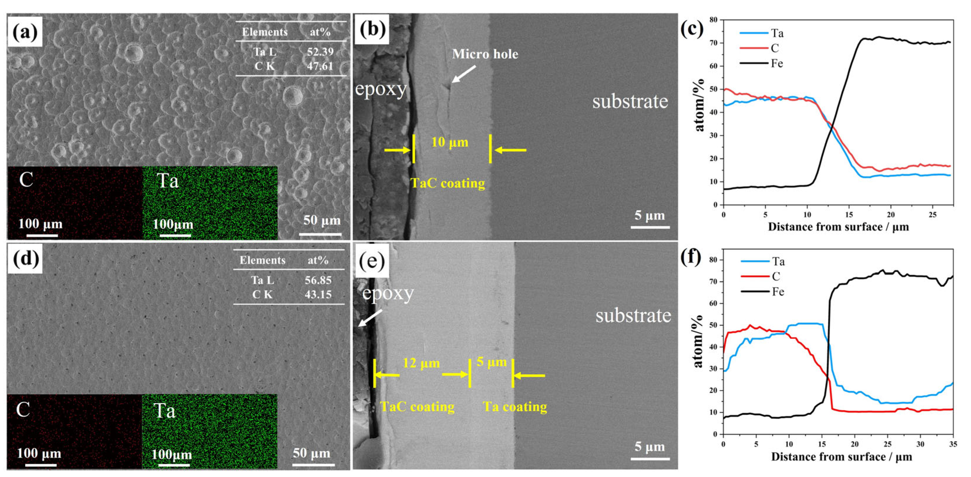
Figure 1 shows the surfaces and cross-sectional SEM morphologies of the TaC and Ta/TaC composite coatings. The TaC coating’s surface exhibited numerous randomly distributed raised cellular structures with diameters ranging from 10 to 20 μm, but no other microdefects were observed, and the surface’s Ta to C elemental ratio was close to 1:1. From the cross-sectional image of the TaC coating in Figure 1b, the overall coating thickness was approximately 10 μm, with a slightly wavy surface. Only slight burr structures were observed at the interface, with no pores, cracks, or other defects, indicating good adhesion to the substrate. A triangular microvoid was present 5 μm from the surface, with a crack extending parallel to the sample’s surface, likely due to internal stress within the film. The surface morphology of the Ta/TaC composite coating, as shown in Figure 1c, indicates a higher quality compared to the TaC coating. The surface is smooth and uniform, with some faintly distributed flake-like structures. The surface Ta content is slightly higher than the C content, possibly due to the outward diffusion of Ta from the interior [22,23]. The surface scan results show that there was no elemental bias, and the difference in morphologies was mainly due to the different deposition processes of the coatings caused by the different substrates, and the collected signals are partially masked by the Ta signals due to the large difference in the relative atomic weights of the C element and Ta, resulting in the color lining of reaction C being much smaller than that of Ta. The cross-sectional morphology and elemental line scan results show that the Ta/TaC composite coating exhibited a bilayer structure, consisting of a 12 μm TaC top layer and an approximately 5 μm Ta transition layer. Despite being composed of two layers, the coating appeared almost seamless internally, with no micro-defects and an indistinct interface between the layers, demonstrating excellent compatibility. Moreover, the interface between the internal Ta transition layer and the steel also showed good bonding, with no micro-defects, effectively merging with the substrate.
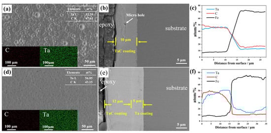
Figure 1.
SEM micrographs of the surfaces and cross-sections of the Ta/TaC coatings: (a) surface and EDS mappings of TaC; (b) cross-section and (c) EDS linescan of TaC; (d) surface and EDS mappings of Ta/TaC; (e) cross-section and (f) EDS linescan of Ta/TaC.
Figure 2 shows the XRD patterns of the TaC and Ta/TaC coatings. Both coatings were primarily composed of the TaC phase, with the four common crystal planes of TaC all appearing without showing significant preferential orientation, which is related to the random cellular growth mode characteristic of the Xu-Tec process [24]. However, in the composite coating, the surface TaC layer showed a relative decrease in the TaC (111) face and an increase in the TaC (220) face, likely due to the different growth substrates. Additionally, the Ta/TaC coating exhibited a weak Ta2C peak at around 32°, consistent with the higher Ta content observed on the surface, as shown in Figure 1c. This is attributed to the diffusion of Ta within the coating during growth, contributing to the appearance of an almost homogeneous structure and providing better adhesion.
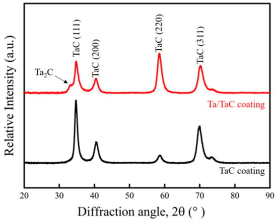
Figure 2.
XRD patterns of the TaC and Ta/TaC coatings.
3.2. Hardness and Scratch Tests Analysis
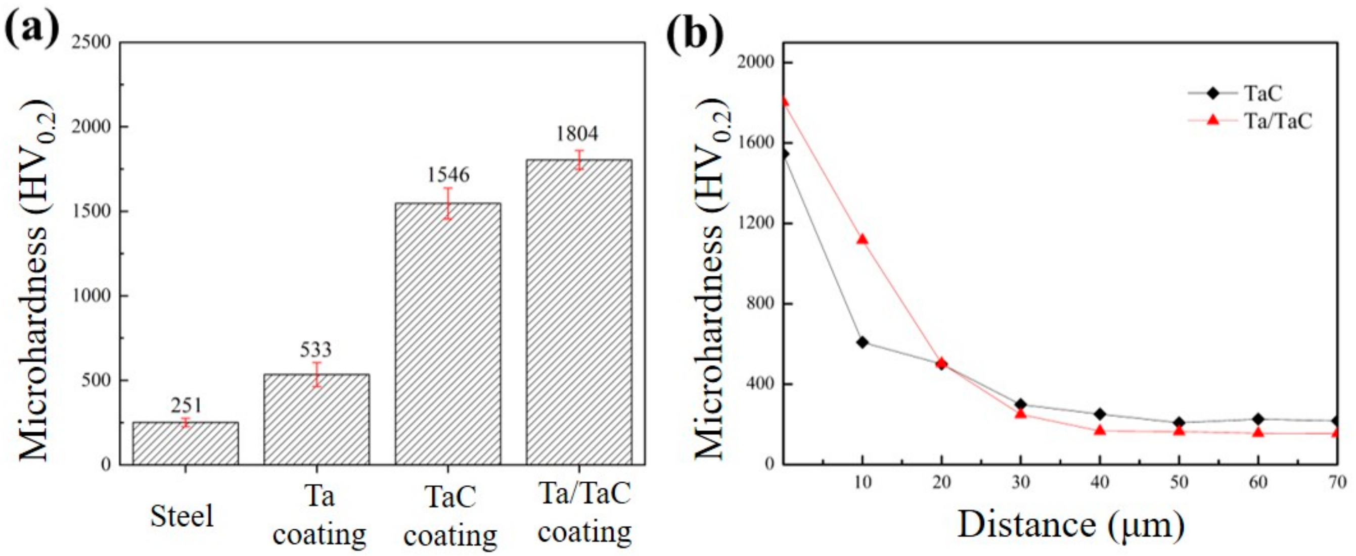
Figure 3 presents the microhardness of the steel matrix, Ta coating, TaC, and Ta/TaC coatings. The average surface microhardness values of the four samples were 251.46 ± 25.68 HV0.2, 533.88 ± 71.64 HV0.2, 1546.38 ± 90.86 HV0.2, and 1804.38 ± 55.82 HV0.2, respectively. The introduction of the Ta transition layer not only significantly enhanced the surface microhardness of the composite coating but also resulted in a more uniform hardness distribution, reflecting the improved uniformity of the coating consistent with the surface morphology’s structure. The cross-sectional hardness variation with depth (Figure 3b) showed a gradient distribution, with a hardness affected depth of about 20 μm. The hardness of the Ta/TaC coating was consistently higher than that of the TaC coating up to a depth of 20 μm. This is mainly due to the increase in thickness of the composite Ta/TaC coating, whereby the Ta layer (more than twice the hardness of the substrate) contributes to the higher hardness of the Ta/TaC-coated sample compared to the TaC-coated sample, thereby enhancing the hardness in the first 20 μm. This gradual change in structure avoids abrupt variations in physical properties between the coating and the substrate, significantly reducing stress concentration damage to the coating and minimizing the potential for coating delamination during wear.
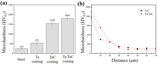
Figure 3.
The microhardness of steel and coatings: (a) surface; (b) cross-sectional hardness varying with the depths of the coatings.
Given that the tribology experiments were carried out at the same load and with the same wear bodies, the contact stress can be evaluated. According to sphere-on-flat Hertzian contact analysis, the maximum Hertzian contact stress, Pmax, is given by the following [25]:
where R is the radius of the friction sphere (Al2O3 ball, 5 mm), E is the elastic modulus of the Al2O3 ball (about 350 GPa), and N is the normal load on the rigid, flat surface (7.3 N). The value of Pmax was calculated to be approximately 1.90 GPa.
In the case of rigid contact at different depths, the stress is not absorbed and is transmitted uniformly from the surface to the underside and, thus, considered invariable. At different angles (angle of the load with horizon) [26], the stress is Pα = Pmax·sinα = 1.9·sinα GPa.
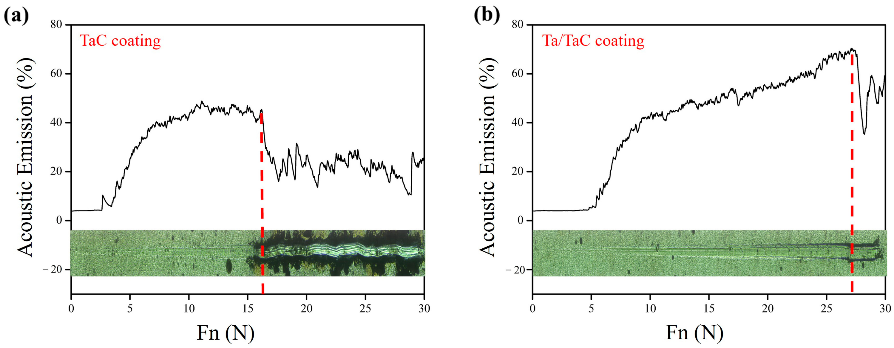
The coating adhesion scratch test results are shown in Figure 4. In the initial stage, because of the high hardness of the TaC, the scratch signal was not significant under low pressure. When the load reached 2.5 N, the signal began to increase, indicating that the coating had begun to experience slight damage, with scratch marks appearing in the region. At a press load of 16 N, the scratch signal suddenly decreased, revealing the bright substrate as the coating was penetrated. The brittle nature of the TaC coating [27,28] caused extensive chipping and spalling along the scratch edges, irregularly distributed on both sides of the scratch, and the edge chipping increased the lateral force on the indenter, causing the scratch trajectory to deviate from a straight line. With the introduction of the Ta transition layer, the adhesion of the composite coating significantly improved. The scratch signal only started to increase at around 5 N, and as the pressure increased, the signal continued to grow, with the scratch width and depth increasing accordingly. At approximately 27 N, the scratch signal sharply dropped, but an examination revealed that the coating was not penetrated, only minor spalling occurred at the scratch edges. Even at the maximum test pressure of 30 N, the coating remained intact, fully covering the sample surface, demonstrating remarkable adhesion. The introduction of the Ta transition layer resulted in a gradual change in the physical properties of the coating in the depth direction, forming an ideal gradient structure that greatly alleviated stress in the composite coating and improved adhesion to the substrate.
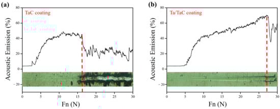
Figure 4.
Acoustic emission (AE) signals and optical images of scratches: (a) TaC coating; (b) Ta/TaC coating.
3.3. Tribology Performance
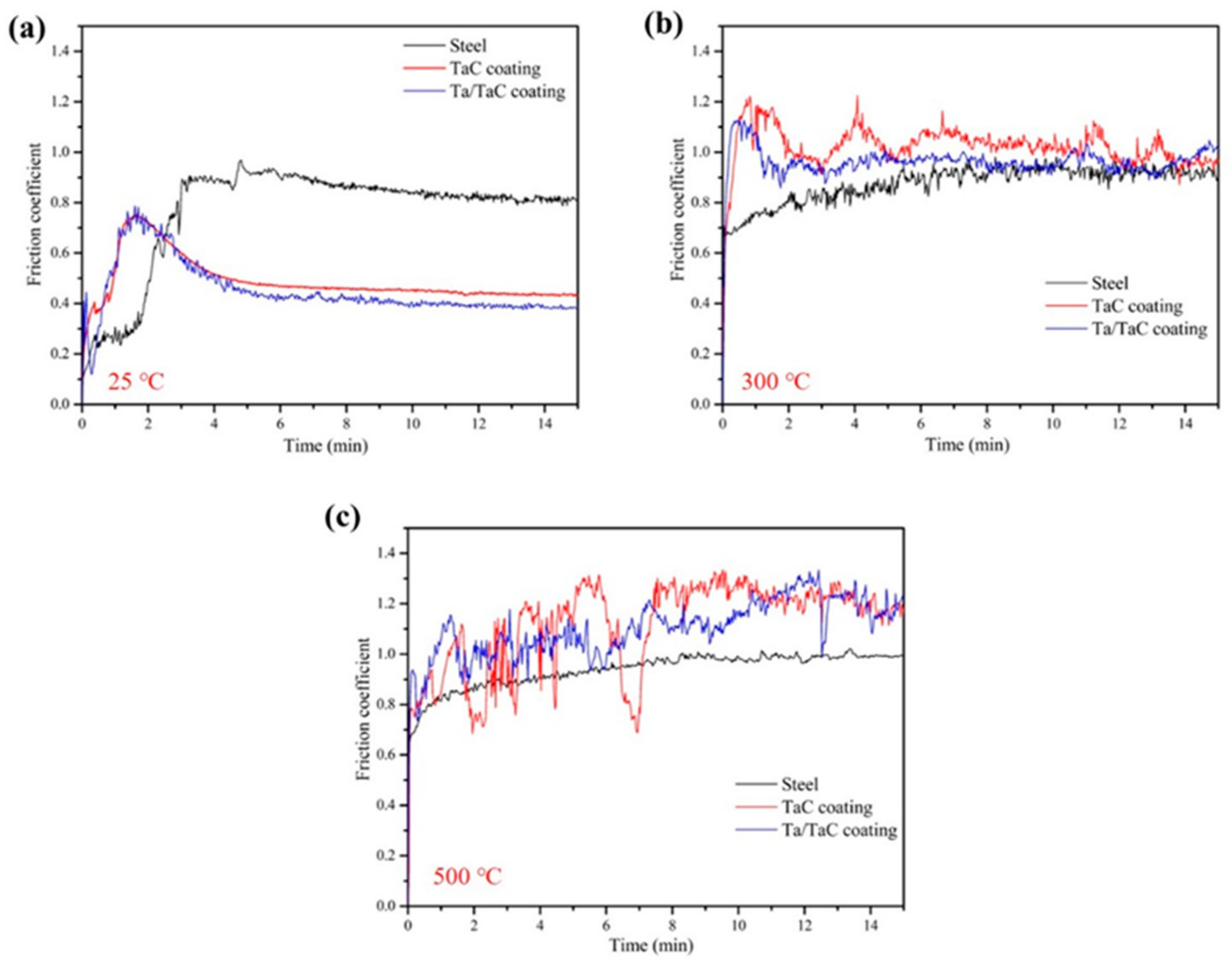
Figure 5 shows the friction coefficient curves of the substrate and the coatings at different temperatures. Generally, during the initial stage of friction and wear, both contact surfaces underwent a running-in period in which the friction coefficient increased. As wear debris was produced, the wear process transitioned from two-body contact to three-body contact, causing the friction coefficient to decrease and stabilize [29]. For the steel substrate, the friction coefficient curve exhibited minor fluctuations, with a slight decrease during the mid-wear period at room temperature. At high temperatures, the friction coefficient rapidly rose and stabilized at around 0.9, indicating a relatively simple wear process. For the coated samples, the friction coefficients of the Ta/TaC coatings were slightly lower than those of the TaC coatings. At room temperature, after passing the running-in period, the friction curves for both coatings begin to decline and stabilize at approximately 0.4. At high temperatures, the friction coefficients exhibited more noticeable fluctuations, skipping the running-in period and directly entering the normal wear stage. At 300 °C, the friction coefficients for the Ta and Ta/TaC coatings fluctuated around 1.0 and 0.9, respectively. At a higher temperature of 500 °C, the friction curves for both coatings oscillated around 1.1 and 1.2, with greater amplitude. Unlike at room temperature, the wear process between the Al2O3 balls and coatings was more complex at high temperatures. Nevertheless, there were no signs of significant coating damage or failure throughout the wear process. In general, the coefficient of friction decreased with increasing temperature due to the lubricating effect of oxides [30,31]. However, in this paper, the friction coefficient of the coating tended to increase with an increase in temperature. The main reason is that the TaC coating had excellent antioxidant properties at the test temperature. The coating surface did not spontaneously form oxides, but because of the low fracture toughness, KIC, of about 2.7–3.4 MPa·m1/2 [32], the coating was easily broken during friction at high temperatures, resulting in increases in the friction coefficient instability [33]. In addition, from the later analysis, it is observed that the abrasion mark morphology of the TaC coating increased the friction contact area at elevated temperatures when the particles on the surface of the coating were flattened, while the Ta/TaC surface became rough and the friction resistance increased, which together led to the increase in the friction coefficient.
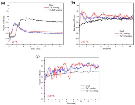
Figure 5.
Friction coefficient curves of the samples: (a) 25 °C; (b) 300 °C; (c) 500 °C.
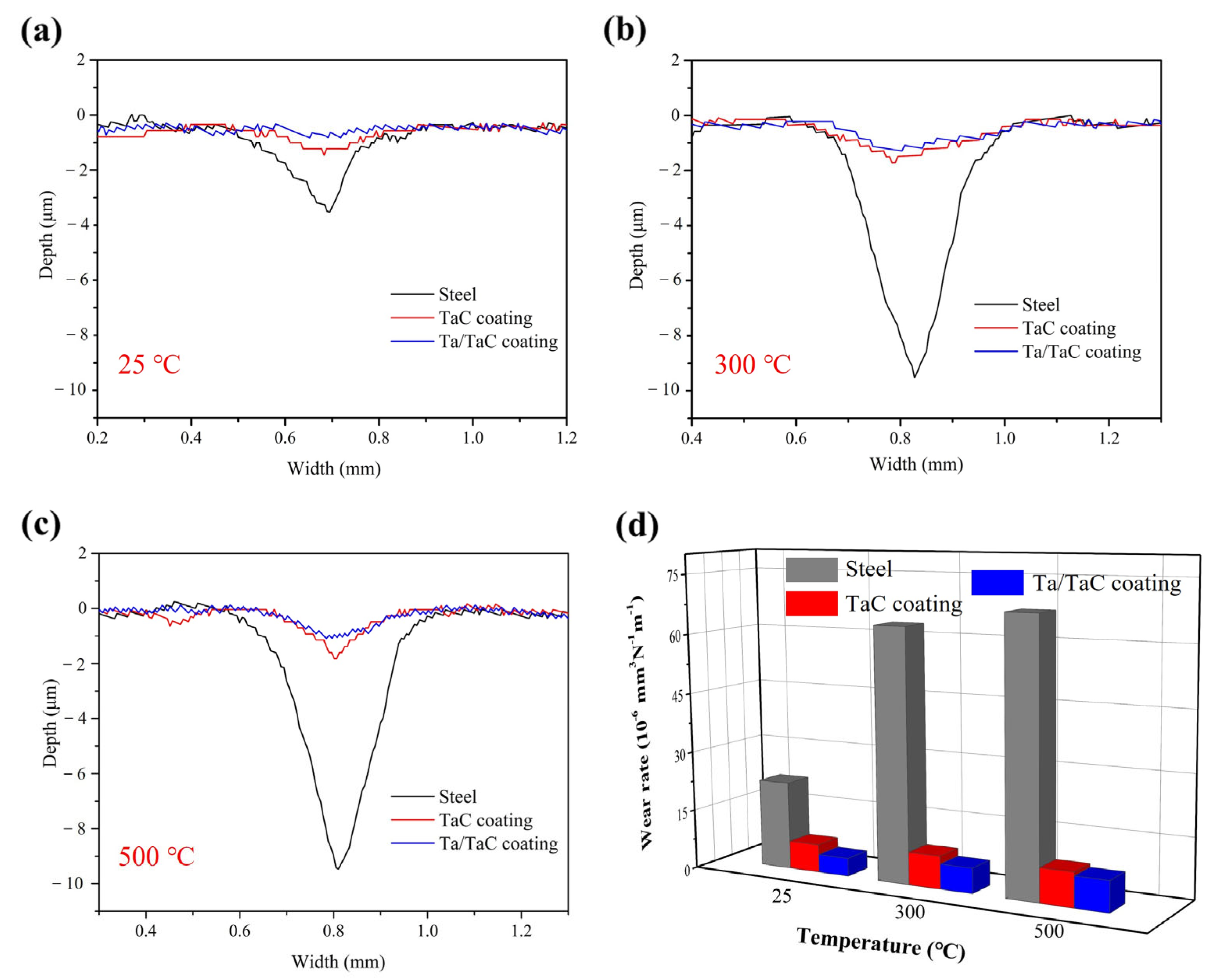
Figure 6 shows the wear profile curves of the substrate and coatings at different temperatures, clearly indicating that the substrate exhibited significantly higher wear loss compared to the two coatings, especially at high temperatures. At 300 °C and 500 °C, the wear depth of the substrate approached 10 μm, and the profile depth of the Ta/TaC coating was slightly better than that of the TaC coating but did not exceed 2 μm. The main reason for the minimal difference in wear profiles between the two coatings is likely that the applied test load did not cause any damage to the TaC coatings, remaining within the load-bearing capacity of the coatings.
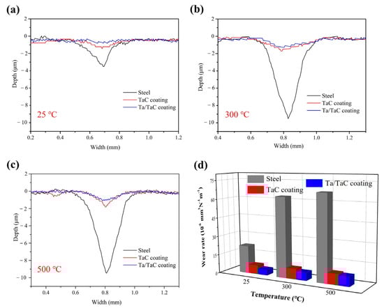
Figure 6.
Wear profiles of the samples at (a) 25 °C, (b) 300 °C, and (c) 500 °C; (d) specific wear rates of the samples.
For the tribological test, the wear rates were calculated with Equation (2), as follows:
where K is the wear rate (mm3·N−1·m−1), V is the wear volume (mm3), F is the normal load (N), and L is the total sliding distance (m). The results are shown in Figure 6d. The specific wear rates of the substrate at different temperatures were 22.06 × 10⁻⁶ mm3·N−1·m−1, 63.17 × 10⁻⁶ mm3·N−1·m−1, and 67.47 × 10⁻⁶ mm3·N−1·m−1, respectively. For the Ta/TaC-coated samples, the specific wear rates were 4.55 × 10⁻⁶ mm3·N−1·m−1, 6.27 × 10⁻⁶ mm3·N−1·m−1, and 7.66 × 10⁻⁶ mm3·N−1·m−1, which are 20.6% (25 °C), 9.9% (300 °C), and 11.4% (500 °C) of the substrates. The protective effect of the coatings was more pronounced at high temperatures, which may be attributed to the oxidation of the substrates in an atmospheric environment, leading to more serious material loss.
3.4. Wear Surface and Mechanism
The wear surfaces and cross-sectional morphologies of the substrate and coatings at 25 °C, 300 °C, and 500 °C are displayed in Figure 7, Figure 8 and Figure 9, respectively, and the corresponding EDS analysis of the wear surfaces are listed in Table 3.
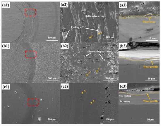
Figure 7.
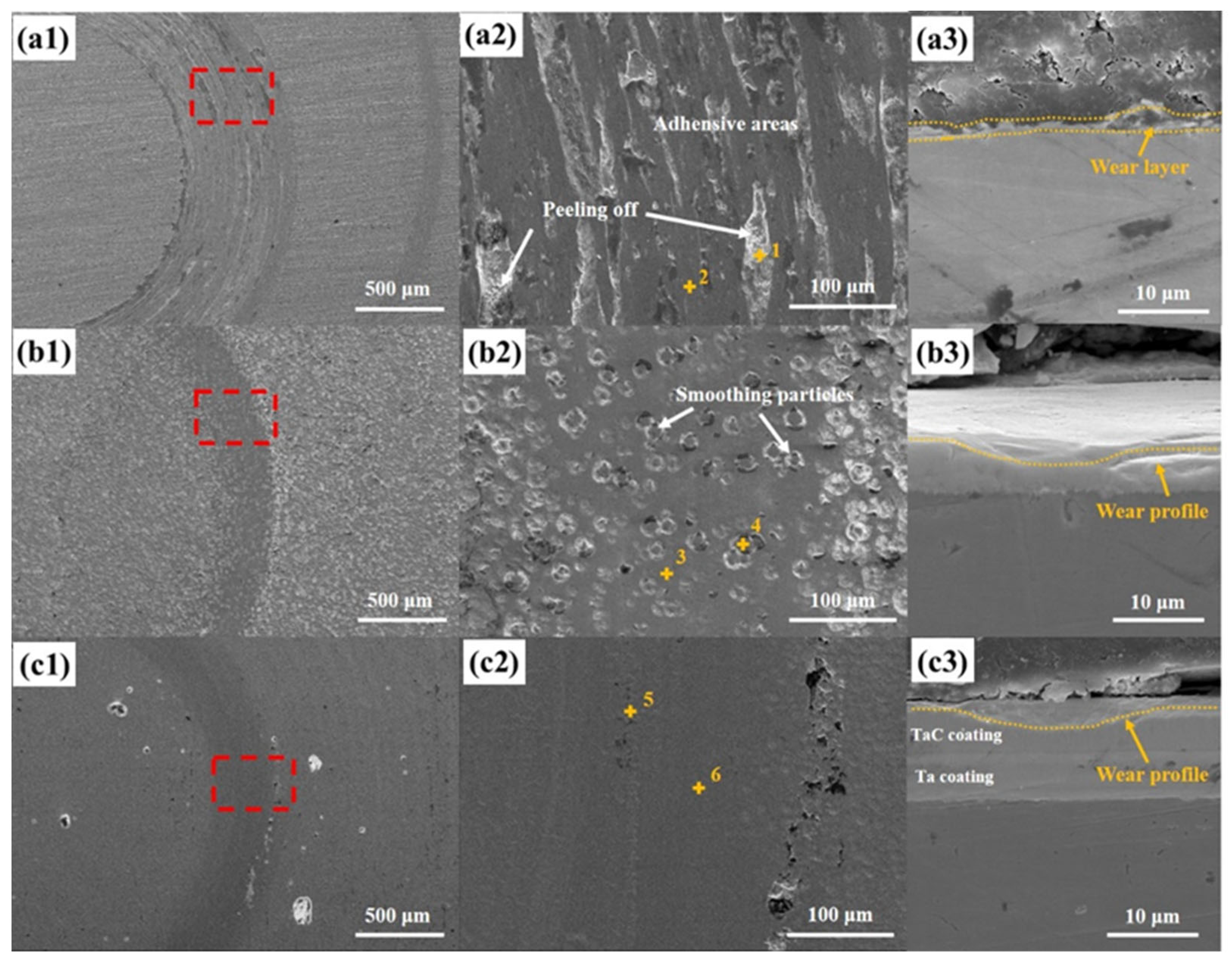
SEM micrographs of the wear surfaces and cross-sections of samples at 25 °C: (a) substrate; (b) TaC coating; (c) Ta/TaC coating. (a2,b2,c2) and (a3,b3,c3) are high-resolution and cross-sectional SEM images of the corresponding regions (marked in red rectangle) in (a1,b1,c1).
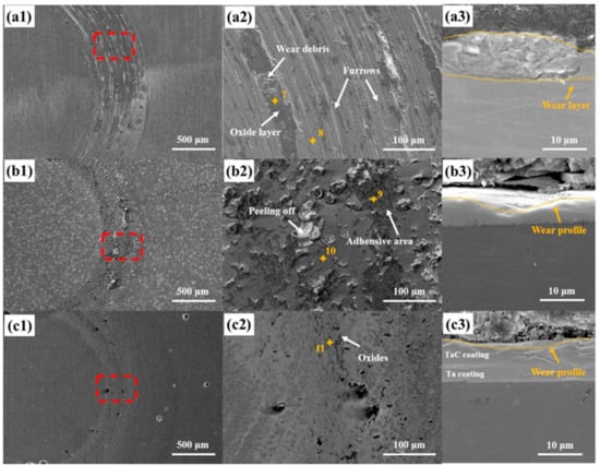
Figure 8.
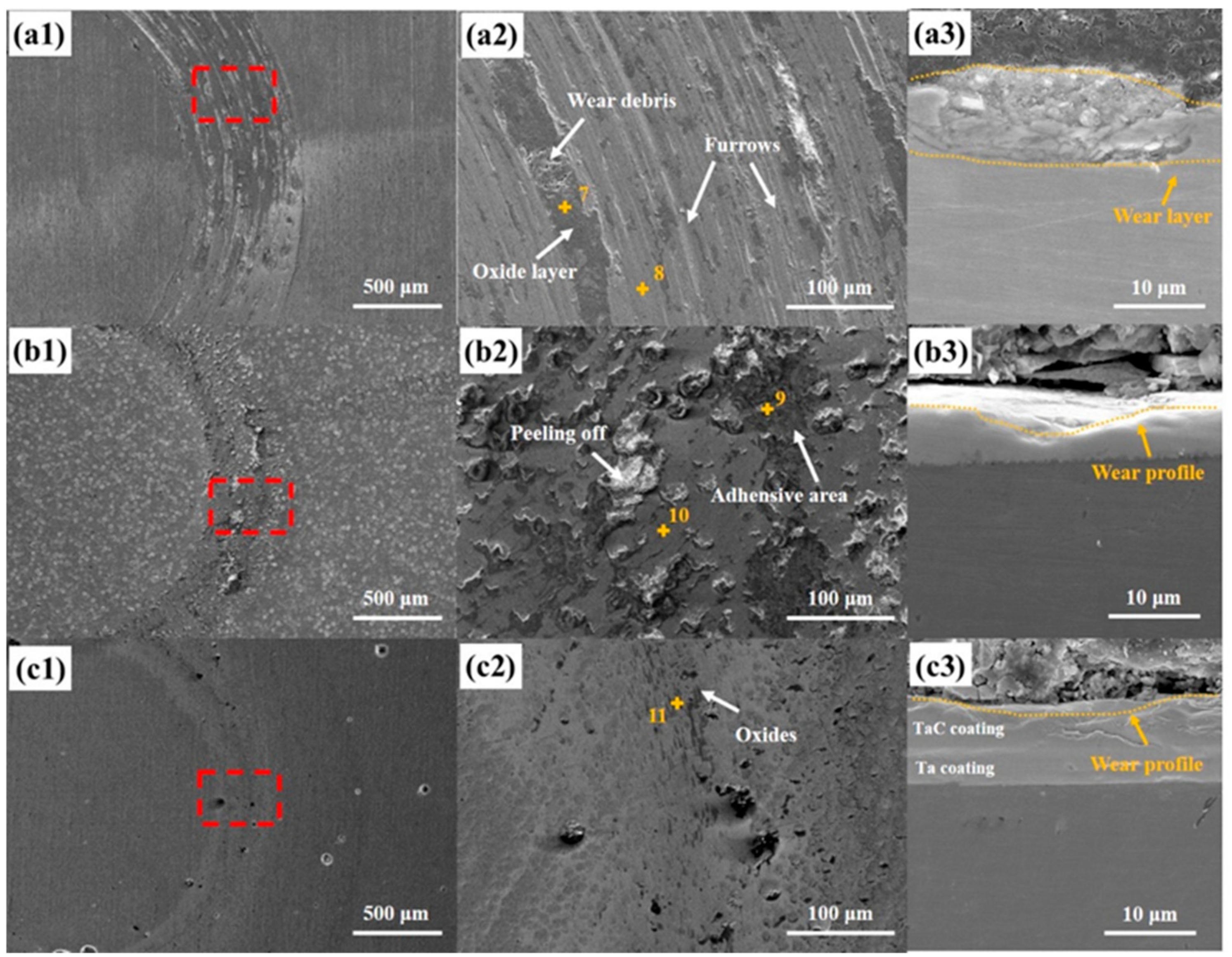
SEM micrographs of the wear surfaces and cross-sections of samples at 300 °C: (a) substrate; (b) TaC coating; (c) Ta/TaC coating. (a2,b2,c2) and (a3,b3,c3) are high-resolution and cross-sectional SEM images of the corresponding regions (marked in red rectangle) in (a1,b1,c1).
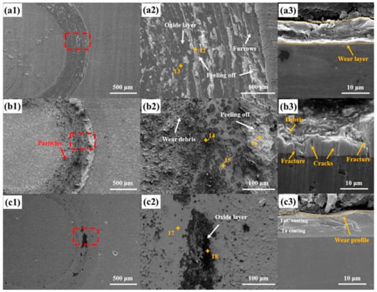
Figure 9.
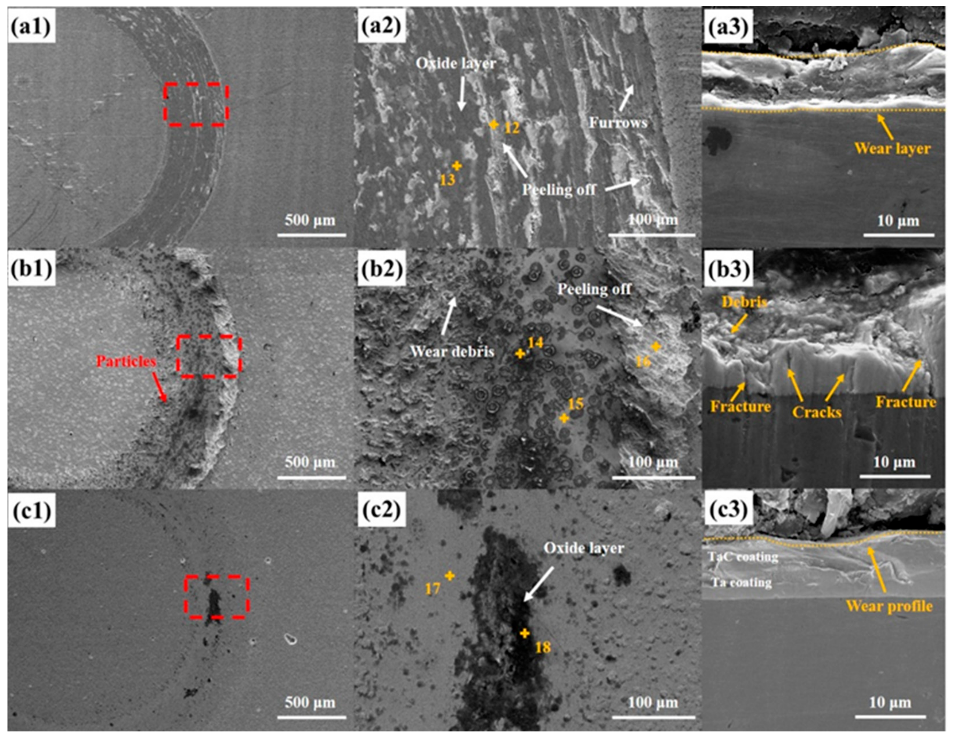
SEM micrographs of the wear surfaces and cross-sections of the samples at 500 °C: (a) substrate; (b) TaC coating; (c) Ta/TaC coating. (a2,b2,c2) and (a3,b3,c3) are high-resolution and cross-sectional SEM images of the corresponding regions (marked in red rectangle) in (a1,b1,c1).
Figure 7a shows the substrate with a wear width exceeding 500 μm. The magnified morphology reveals numerous elongated spalling areas with a few wear debris particles present in the spalling regions. Because of the significantly higher hardness of the Al2O3 ball compared to the steel substrate, the wear process primarily resulted in adhesive wear and some spalling, with the Al2O3 ball itself experiencing virtually no wear loss. For the TaC-coated sample (Figure 7b), huge amounts of raised particles were observed on the surface. In the initial stage of wear, these particles created greater resistance, which gradually stabilized as the particles were worn down (Figure 7(b2)), consistent with the friction coefficient curve changes in Figure 5a. The Ta/TaC-coated sample showed less pronounced wear marks on the surface, and magnification revealed a smoother wear area with minor extruded wear debris accumulation at the edges. The EDS analyses of the wear regions for the three samples are presented in Table 3. The adhesive region of the substrate (spot 2) and the raised area of the TaC coating (spot 4) showed higher oxygen contents, primarily due to increased oxidation from the heat accumulation in these areas during wear contact with the Al2O3 ball. The Ta/TaC coating surface demonstrated a more uniform wear process with a flat wear area. The Ta and C elemental contents remained approximately 1:1 at the two tested points, indicating no change in the surface phase composition of the coating. From the Ta-C composition ratio in Table 3, the significant increase in the percentage of C content in spot 3 may be due to the contamination of the samples during the preservation period while waiting for the test process; the increase in the percentage of Ta content in spot 4 may be due to the oxidation of the coating surface at high temperatures, as well as the release of the C element in the form of a gas, which led to an increase in the percentage of residual Ta. Further observation and analysis of the wear cross-sections revealed that the steel substrate’s surface had a layer of wear debris and some spalling, resulting in an uneven surface. The cross-sectional morphologies of the single and composite coatings were largely consistent, with only minor depressions in the center of the wear areas, remaining intact and exhibiting excellent wear resistances.
Figure 8a shows that the wear surface morphology of the substrate at 300 °C was similar to that at room temperature; however, at high magnification (Figure 8(a2)) it showed a quite different morphology. Unlike the adhesive wear observed at room temperature, this wear region contained numerous furrows and dark areas resembling an adhesive wear morphology. EDS analysis (spot 7) indicates that the oxygen content in dark areas was significantly higher than in the furrowed regions (spot 8), exhibiting oxidative wear. The oxidation layer partially spalled off, forming areas of wear debris accumulation, and the substrate was mainly characterized by abrasive wear and slight oxidation wear mechanism. The cross-sectional morphology of the wear area (Figure 8(a3)) shows severe fragmentations, with numerous particles and fragments accumulating to form a thicker wear layer. The TaC-coated sample also suffered more severe wear, with some spalling areas appearing in the wear region, and the raised areas nearly worn flat and partially connected, exhibiting slight adhesive wear. According to the EDS results in Table 3, the previously raised particles on the coating experience severe oxidation, with small amounts of Al transferred from the Al2O3 ball detected. The flatter areas of the original surface also showed slight oxidation but no Al transfer. At this temperature, the Ta/TaC-coated sample still showed only minor wear marks, with some dark particulate matter appearing in the wear region. The EDS results (spot 11) reveal that these particles were primarily oxide accumulations, with no Al transfer detected. The cross-sectional morphology of the TaC and Ta/TaC coatings shows that they both maintained good coating structures, providing excellent protection for the substrate material. Additionally, the composite coating demonstrated superior wear resistance, with less pronounced wear marks compared to the single-layer TaC coating. This is mainly due to the smooth surface morphology of the composite coating, which provides a larger area to support the wear load, significantly reducing the damage to the coating from the Al2O3 ball.
At the testing temperature of 500 °C (Figure 9), the oxidation of the substrate surface intensified, leading to significant changes in the wear area’s morphology. The surface exhibited a substantial oxidation layer, with numerous oxides participating in the wear process. These oxides contributed to adhesion and spalling when interacting with the Al2O3 balls, forming several spallation areas. Simultaneously, harder oxide particles were engaged in abrasive wear with the substrate, exacerbating material damage. The EDS analysis revealed that the presence of hard oxides on the material surface facilitated the transfer of trace amounts of Al elements. The cross-sectional image shows a thick and continuous wear layer, which is more prone to substantial spalling. Notably, the TaC-coated samples also exhibited severe damage, with significant abrasive accumulation on the inner side of the wear tracks. On the outer side, a higher linear velocity led to brittle flaking of the coating. The wear of spot 14 experienced more intense wear compared to flat areas (spot 15), with increased transfers of O and Al contents compared to the edge spallation site (spot 16). Further observation of the wear cross-section revealed that although the TaC coating remained attached to the substrate’s surface, numerous cracks and severe edge fractures were present within the coating. This is primarily due to the inherent brittleness of the TaC coating and its mismatch with the physical properties of the substrate, leading to stress concentration. However, with the addition of a Ta transition layer, the wear performance of the Ta/TaC coating improved significantly. The EDS results and analysis, as presented in Figure 9c, show only minor dark oxidation regions (spot 18) at the middle position of the wear area, with only slight wear in other areas. In addition, spot 18 exhibited a phenomenon (high C content) similar to spot 3 from the Ta-C composition ratio. The Ta/TaC coating remained intact in the cross-sectional image, with no internal cracks or fractures. In summary, the Ta/TaC composite coating maintained good adhesion to the substrate at high temperatures, effectively protecting the internal substrate and demonstrating excellent high-temperature wear resistance.
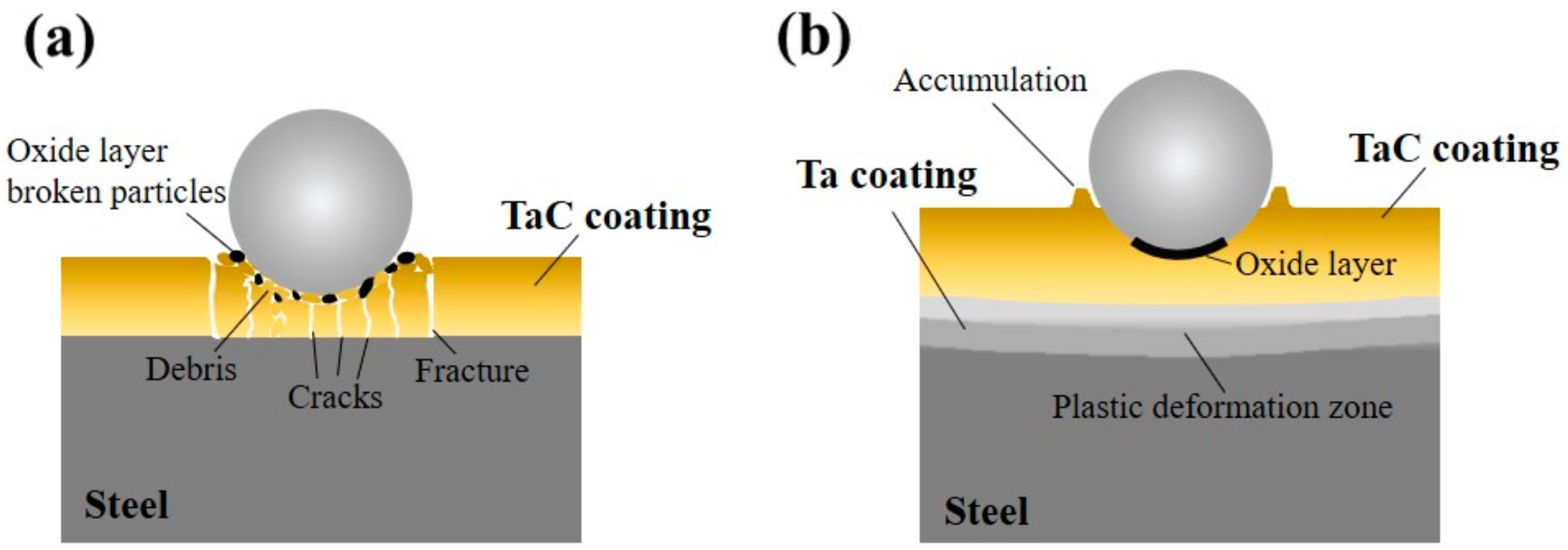
Figure 10 illustrates the wear mechanisms of the TaC and Ta/TaC coatings at high temperatures. Under the load of the wear ball, the surface asperities of the single-layer TaC coating were rapidly worn down, generating an oxide layer. The oxide layer breaks off from the bottom of the TaC coating during subsequent wear, forming broken oxide particles. Some of these oxide particles accumulate at the edges of the wear track, while others, along with the Al2O3 ball, further damage the coating. At higher temperatures, the steel material undergoes slight softening. Because of the thermal mismatch between the substrate and the TaC coating, combined with external loading, the coating cannot accommodate the deformation, resulting in numerous internal cracks. On the side of the wear track with higher linear velocity, the edge of the TaC coating experiences severe stress concentration, leading to fracture structures that can no longer effectively protect the underlying substrate. In contrast, the introduction of the Ta transition layer, with excellent plastic deformation ability [34], exhibits improved compatibility with the TaC layer, allowing for better absorption of the deformation energy of the surface TaC layer. This enables the coating to deform synergistically with the substrate, creating a zone of plastic deformation that significantly reduces internal stress and stress concentration within the coating [35]. Consequently, only minor debris accumulation and wear oxide layers are observed at the edges and middle positions of the wear area, respectively. The overall integrity of the coating remains intact and well-adhered to the substrate, thereby providing excellent protection for the underlying material.

Figure 10.
Schematic diagram of the wear mechanism of the (a) TaC and (b) Ta/TaC coatings at high temperature.
4. Conclusions
In this study, TaC and Ta/TaC coatings with excellent high-temperature wear resistance were successfully designed and deposited on 30CrNi2MoVA steel, which is used for artillery barrels, using double-glow plasma surface alloying technology. The main conclusions of this study are as follows:
- The prepared TaC and Ta/TaC coatings had thicknesses of approximately 10 μm and 17 μm, respectively. Both coatings exhibited dense internal structures with no microdefects at the interface with the substrate. The composite two-layer coating was almost seamless, forming a single entity with better surface smoothness. The XRD results indicate that the surface of the TaC coating was a pure TaC phase, while the composite coating showed a slight formation of the Ta2C phase due to the outward diffusion of Ta elements.
- Benefiting from the excellent mechanical properties of the TaC ceramic, the surface microhardnesses of the TaC and Ta/TaC-coated samples increased by approximately five times and six times, respectively, compared to the substrate. The cross-sectional hardnesses of both coatings exhibited a gradient distribution, affecting a depth of about 30 μm. The scratch test results demonstrate that the introduction of the Ta transition layer significantly enhanced the coating toughness, with the Ta/TaC coating exhibiting a scratch adhesion strength exceeding 30 N, more than double that of the TaC coating.
- The wear results show that both the TaC and Ta/TaC coatings significantly improved the wear resistance of the material, especially at high temperatures. The Ta/TaC coating displayed more stable friction coefficient curves, indicating a more stable wear performance, and a lower specific wear rate, approximately 11.4% of that of the substrate at 500 °C.
- As the wear temperature increased, the wear mechanism of the substrate transitioned from adhesive wear to abrasive and oxidation wear, forming an easily spallable wear layer on the surface. Both coatings exhibited only slight wear at room temperature, and showed slight oxidation wear at high temperatures. At 500 °C, although the single-layer TaC coating remained adhered to the substrate, thermal mismatch, as well as wear load-induced stress concentration, led to numerous internal cracks and edge fractures in the wear track. In contrast, the good compatibility between the Ta transition layer and TaC layer allowed for cooperative deformation with the substrate, creating a plastic deformation zone that reduced internal stresses and the stress concentration, maintaining an intact structure.
Author Contributions
K.Y., Methodology, Formal analysis, Writing—original draft, Investigation, and Supervision; X.L., Investigation, Writing—original draft, and Methodology; B.D., Data curation, Formal analysis, and Writing—original draft; Z.L., Data curation, Formal analysis, and Investigation; X.C., Formal analysis and Methodology; D.W., Writing—original draft, Investigation, and Funding acquisition; S.L., Investigation, Writing—review and editing, and Resources; P.Z., Project administration, Conceptualization, and Resources. All authors have read and agreed to the published version of the manuscript.
Funding
This work was supported by the Science and Technology on Particle Transport and Separation Key National Defense Laboratory (2022-JCJQ-LB-004).
Institutional Review Board Statement
The study did not require ethical approval.
Informed Consent Statement
The study did not involve humans.
Data Availability Statement
The datasets generated during and/or analyzed during the current study are available from the corresponding author on reasonable request.
Conflicts of Interest
The authors declare that they have no known competing financial interests or personal relationships that could have appeared to influence the work reported in this paper.
References
- Li, X.; Zang, Y.; Mu, L.; Lian, Y.; Qin, Q. Erosion analysis of machine gun barrel and lifespan prediction under typical shooting conditions. Wear 2020, 444–445, 203177. [Google Scholar] [CrossRef]
- Wei, S.; Wang, G.; Zhao, X.; Zhang, X.; Rong, Y. Experimental study on vacuum carburizing process for low-carbon alloy steel. J. Mater. Eng. Perform. 2014, 23, 545–550. [Google Scholar] [CrossRef]
- Xu, F.; Yang, G.; Wang, L. Artillery structural dynamic responses optimization based on Stackelberg game method. J. Low Freq. Noise Vib. Act. Control 2022, 41, 140–159. [Google Scholar] [CrossRef]
- Niu, Y.; Xing, L.; Yang, F.; Li, H.; Chen, M.; Zhu, S.; Wang, F. Phase structure of sputtered Ta coating and its ablation behavior by laser pulse heating (LPH). J. Mater. Sci. Technol. 2021, 65, 7–17. [Google Scholar] [CrossRef]
- Shukla, P.; Awasthi, S.; Ramkumar, J.; Balani, K. Protective trivalent Cr-based electrochemical coatings for gun barrels. J. Alloys Compd. 2018, 768, 1039–1048. [Google Scholar] [CrossRef]
- Jani, H.; Kenichiro, M.; Kristoffer, M.; Miika, M.; Marko, V.; Jyrki, R.; Mikko, R.; Markku, L. Rhenium metal and rhenium nitride thin films grown by atomic layer deposition. Angew. Chem. 2018, 130, 14746–14750. [Google Scholar]
- Betiuk, M.; Domanowski, P. Obtaining the CrN coating inside the barrel using a cylindrical magnetron with a dynamic magnetic field. AIP Conf. Proc. 2018, 2017, 020002. [Google Scholar]
- Storm, R.; Withers, J.; Ramos, R.; Loutfy, R. Fabrication of Si3N4 Gun Barrel Liners for Very High Temperature Erosion Resistant Gun Barrels. Mater. Manuf. Process. 2012, 27, 875–877. [Google Scholar] [CrossRef]
- Alam, M.; Das, A. Advancement in cermet based coating on steel substrate: A review. Mater. Today Proc. 2022, 56, 805–810. [Google Scholar] [CrossRef]
- Chung, K.; Lee, R.; Readdy, A. Cannon Wear and Erosion Science and Technology Objective Program (STO) 155-mm Projectile Rotating Band/Obturation for Extended Range. Technical Report ARMET-TR-15001. 2015. Available online: https://apps.dtic.mil/sti/citations/ADA620119 (accessed on 1 June 2015).
- Wu, B.; Fang, L.; Chen, X.; Zou, Z.; Yu, X.; Chen, G. Fabricating aluminum bronze rotating band for large-caliber projectiles by high velocity arc spraying. J. Therm. Spray Technol. 2014, 23, 447–455. [Google Scholar] [CrossRef]
- Li, Q.; Hu, M.; Zhang, P.; Guo, C.; Niu, Q. Isothermal oxidation behavior and thermal shock resistance of three-kind Cr coatings on PCrNi3MoVA steel. Dig. J. Nanomater. Biostruct. 2020, 15, 721–732. [Google Scholar] [CrossRef]
- Wang, S.; Wang, C.; Li, W. Thermodynamic Coupling Simulation of CrN/Cr Composite Coating Barrel Bore. Coatings 2021, 11, 1358. [Google Scholar] [CrossRef]
- Barnett, B.; Trexler, M.; Champagne, V.; Pepi, M. Toxic metal reduction and life extension of gun barrel liners through cold sprayed refractory metals. Int. J. COMADEM 2016, 19, 51. [Google Scholar]
- Barnett, B.; Trexler, M.; Champagne, V. Cold Sprayed Refractory Metals for Chrome Reduction in Gun Barrel Liners. Int. J. Refract. Met. Hard Mater. 2015, 53, 139–143. [Google Scholar] [CrossRef]
- Niu, Y.; Chen, M.; Wang, J.; Yang, L.; Guo, C.; Zhu, S.; Wang, F. Preparation and thermal shock performance of thick α-Ta coatings by direct current magnetron sputtering (DCMS). Surf. Coat. Technol. 2017, 321, 19–25. [Google Scholar] [CrossRef]
- Miller, M.; Campo, F.; Troiano, E.; Smith, S.; Rosset, W. Explosive bonding of refractory metal liners. Mater. Manuf. Process. 2012, 27, 882–887. [Google Scholar] [CrossRef]
- Withers, J.; Storm, R.; Shapovalov, V.; Loutfy, R. An All Titanium Gun Barrel Containing a TiCN Liner. Mater. Manuf. Process. 2012, 27, 878–881. [Google Scholar] [CrossRef]
- Men, X.; Tao, F.; Gan, L.; Li, Y.; Liu, Z. Erosion and wear resistance of Cr3C2-NiCr composite ceramic coating for gun barrel. IOP Conf. Ser. Mater. Sci. Eng. 2019, 678, 012075. [Google Scholar] [CrossRef]
- Rivard, J.; Blue, C.; Harper, D.; Stiglich, J.; Ramachandran, G.; Champagne, V. High-density infrared cladding of Ta on steel. Mater. Manuf. Process. 2006, 21, 612–617. [Google Scholar] [CrossRef]
- Xu, Z.; Huang, J.; Wu, H.; Xu, Z.; Liu, X.; Lin, N.; Wei, D.; Zhang, P. A modern-day alchemy: Double glow plasma surface metallurgy technology. AIP Adv. 2022, 12, 030702. [Google Scholar] [CrossRef]
- Chen, X.; Zhang, P.; Wei, D.; Ding, F.; Li, F.; Wei, X.; Ma, S. Preparation and characterization of Cr/CrC multilayer on γ-TiAl alloy by the double glow plasma surface alloying technology. Mater. Lett. 2018, 215, 292–295. [Google Scholar] [CrossRef]
- Qiu, Z.; Zhang, P.; Wei, D.; Wei, X.; Chen, X. A study on tribological behavior of double-glow plasma surface alloying W-Mo coating on gear steel. Surf. Coat. Technol. 2015, 278, 92–98. [Google Scholar] [CrossRef]
- Qi, Y.; Liang, W.; Miao, Q.; Lin, H.; Yi, J.; Gao, X.; Song, Y. Characterization of a CrN/Cr gradient coating deposited on carbon steel and synergistic erosion-corrosion behavior in liquid-solid flow impingement. Ceram. Int. 2023, 49, 33925–33933. [Google Scholar] [CrossRef]
- Chen, X.; Du, Y.; Chung, Y.W. Commentary on using H/E and H3/E2 as proxies for fracture toughness of hard coatings. Thin Solid Films 2019, 688, 137265. [Google Scholar] [CrossRef]
- Yaghoubi, M.; Tavakoli, H. Hertzian Contact Stress. In Mechanical Design of Machine Elements by Graphical Methods; Materials Forming, Machining and Tribology; Springer: Cham, Switzerland, 2022. [Google Scholar]
- Silvestroni, L.; Pienti, L.; Guicciardi, S.; Sciti, D. Strength and toughness: The challenging case of TaC-based composites. Compos. Part B Eng. 2015, 72, 10–20. [Google Scholar] [CrossRef]
- Smith, C.; Ross, M.; De Leon, N.; Weinberger, C.; Thompson, G. Ultra-high temperature deformation in TaC and HfC. J. Eur. Ceram. Soc. 2018, 38, 5319–5332. [Google Scholar] [CrossRef]
- Shi, X.; Liskiewicz, T.; Beake, B.; Chen, J.; Wang, C. Tribological performance of graphite-like carbon films with varied thickness. Tribol. Int. 2020, 149, 105586. [Google Scholar] [CrossRef]
- Roy, A.; Munagala, V.N.V.; Patel, P.; Sharifi, N.; Alidokht, S.; Makowiec, M.; Chromik, R.; Moreau, C.; Stoyanov, P. Friction and wear behavior of suspension plasma sprayed tantalum oxide coatings at elevated temperatures. Surf. Coat. Technol. 2023, 452, 129097. [Google Scholar] [CrossRef]
- Su, W.; Niu, S.; Huang, Y.; Wang, C.; Wen, Y.; Li, X.; Deng, C.; Deng, C.; Liu, M. Friction and wear properties of plasma-sprayed Cr2O3–BaCrO4 coating at elevated temperatures. Ceram. Int. 2022, 48, 8696–8705. [Google Scholar] [CrossRef]
- Cedillos-Barraza, O.; Grasso, S.; Al Nasiri, N.; Jayaseelan, D.; Reece, M.; Lee, W. Sintering behaviour, solid solution formation and characterisation of TaC, HfC and TaC-HfC fabricated by spark plasma sintering. J. Eur. Ceram. Soc. 2016, 36, 1539–1548. [Google Scholar] [CrossRef]
- Ouyang, J.; Sasaki, S. Unlubricated friction and wear behavior of low-pressure plasma-sprayed ZrO2 coating at elevated temperatures. Ceram. Int. 2001, 27, 251–260. [Google Scholar] [CrossRef]
- Tan, Z.; Wu, X.; Guo, J.; Zhu, W. Toughness mechanism and plastic insensitivity of submicron second phase Ta in a novel Ta-Hf6Ta2O17 composite ceramic. Ceram. Int. 2023, 49, 1932–1939. [Google Scholar] [CrossRef]
- Qi, Y.; Liang, W.; Miao, Q.; Yi, J.; Lin, H.; Liu, Y.; Ma, H. Role of the nitrogen ratio on mechanical properties and wear resistance of CrN/Fe functionally graded coating produced by double glow plasma alloying. Appl. Surf. Sci. 2022, 585, 152735. [Google Scholar] [CrossRef]

Disclaimer/Publisher’s Note: The statements, opinions and data contained in all publications are solely those of the individual author(s) and contributor(s) and not of MDPI and/or the editor(s). MDPI and/or the editor(s) disclaim responsibility for any injury to people or property resulting from any ideas, methods, instructions or products referred to in the content. |
© 2024 by the authors. Licensee MDPI, Basel, Switzerland. This article is an open access article distributed under the terms and conditions of the Creative Commons Attribution (CC BY) license (https://creativecommons.org/licenses/by/4.0/).