Article

A3B Zn(II)-Porphyrin-Coated Carbon Electrodes Obtained Using Different Procedures and Tested for Water Electrolysis

by
Bogdan-Ovidiu Taranu
1,*,
Florina Stefania Rus
1 and
Eugenia Fagadar-Cosma
2
1
National Institute of Research and Development for Electrochemistry and Condensed Matter, Dr. A. Paunescu Podeanu Street No. 144, 300569 Timisoara, Romania
2
Institute of Chemistry “Coriolan Dragulescu”, Mihai Viteazu Ave. 24, 300223 Timisoara, Romania
*
Author to whom correspondence should be addressed.
Coatings 2024, 14(8), 1048; https://doi.org/10.3390/coatings14081048
Submission received: 21 July 2024 / Revised: 12 August 2024 / Accepted: 15 August 2024 / Published: 16 August 2024
(This article belongs to the Special Issue Environmentally Friendly Energy Conversion Materials and Thin Films)

Abstract

:
In the context of water electrolysis being highlighted as a promising technology for the large-scale sustainable production of hydrogen, the water-splitting electrocatalytic properties of an asymmetrically functionalized A3B zinc metalated porphyrin, namely, Zn(II) 5-(4-pyridyl)-10,15,20-tris(4-phenoxyphenyl)-porphyrin, were evaluated in a wide pH range. Two different electrode manufacturing procedures were employed to outline the porphyrin’s applicative potential for the O2 and H2 evolution reactions (OER and HER). The electrode, manufactured by coating the catalyst on a graphite support from a dimethylsulfoxide solution, displayed electrocatalytic activity for the OER in an acidic electrolyte. An overpotential value of 0.44 V (at i = 10 mA/cm2) and a Tafel slope of 0.135 V/dec were obtained. The modified electrode that resulted from applying a Zn(II)-porphyrin-containing catalyst ink onto the same substrate type was identified as a bifunctional water-splitting catalyst in a neutral medium. OER and HER overpotentials of 0.78 and 1.02 V and Tafel slopes of 0.39 and 0.249 V/dec were determined. This is the first Zn(II)-porphyrin to be reported as a heterogenous bifunctional water-splitting electrocatalyst in neutral aqueous electrolyte solution and is one of very few porphyrins behaving as such. The TEM analysis of the porphyrin’s self-assembly behavior revealed a wide variety of architectures.

1. Introduction

Hydrogen is currently being considered as a promising clean energy carrier of the future [1]. Out of the H2-generating technologies that are non-polluting, electrochemical water splitting is regarded as the most likely path to replace the existing fossil-fuel-oriented infrastructure [2], especially when combined with renewable energy sources such as solar, wind, and tidal energy [3].
Due to the currently heightened interest in water electrolysis, which is a clean, safe, and simple process [4], many research studies are being reported every year that focus on the synthesis and evaluation of materials with electrocatalytic properties for at least one of the two half-cell reactions involved in the water-splitting process [5]. Based on which reaction they catalyze, the electrocatalysts used for water splitting can be categorized into catalysts for the oxygen evolution reaction (OER) occurring at the anode, for the hydrogen evolution reaction (HER) unfolding at the cathode, or into bifunctional catalysts for overall water splitting [6]. The pH of the electrolyte in which electrocatalytic materials exhibit catalytic activity provides another way to classify them, as electrocatalysts for acidic, basic, and neutral media [7]. Acidic solutions are thermodynamically favorable for the HER because due to more sluggish kinetics, the HER is more demanding in basic and neutral environments, while alkaline solutions are more suitable for electrochemically stable OER electrocatalysts with acceptable activity [8,9,10]. This situation complicates the identification of bifunctional water electrolysis catalysts exhibiting activity for both half-cell reactions in the same medium. As for materials with high catalytic activity in neutral electrolytes, while they are scarcer, they are also very desirable given that a neutral water electrolysis ensemble could allow for the direct decomposition of the abundantly available seawater [9].
Currently, noble metals such as Pt, Pd, Ru, Rh, and Ir are widely recognized as the most efficient OER and HER catalysts [11]. In fact, the benchmark electrocatalyst for the HER is Pt, while RuO2 and IrO2 fulfill this role for the OER [12]. However, the scarcity and high cost of noble metals impede their use in large-scale commercial applications. This has led to a shift in the search for new electrocatalysts toward noble-metal-free materials, with an emphasis on the cost-effective and earth-abundant transition metals [13]. In this sense, zinc has been used to obtain compounds with water-splitting catalytic activity [14,15], including metalloporphyrins having the zinc cation as their central metal ion [16,17].
Porphyrins are a class of organic dyes present in nature and also easily synthesizable. Their shared characteristic is a macrocycle comprising four pyrrole units interconnected through methine bridges that can bind in its center almost all metal ions (forming metalloporphyrins) and can be functionalized with a wide variety of functional moieties [18,19]. Porphyrin molecules have the ability to self-assemble by spontaneous association through non-covalent interactions, resulting in supramolecular aggregates which, compared with the individual molecules, display different and usually more useful application-related characteristics [20,21].
The various properties of porphyrin derivatives recommend them for a wide variety of applications [22], including in electrocatalysis [23]. Regarding the electrochemical water-splitting properties of metalloporphyrins, they have been studied at least since 1985 [24] and they are also of current interest [21,23,25].
Herein, the OER and HER electrocatalytic properties of an A3B zinc metalated porphyrin, namely Zn(II) 5-(4-pyridyl)-10,15,20-tris(4-phenoxyphenyl)-porphyrin, are investigated in a wide pH range using two different experimental protocols. The first protocol exploits the self-assembly property of the specified porphyrin derivative deposited from various organic solvents on a carbon substrate, while the second one is based on a procedure for water electrolysis studies that is rarely used for porphyrin-based electrocatalysts [26] and is often employed for inorganic electrocatalytic materials [27,28,29]. The experimental data show that out of the electrodes developed with the first manufacturing procedure, the sample obtained using dimethylsulfoxide as solvent was the most electrocatalytically active for the OER in an acidic medium. As for the metalloporphyrin-based electrode developed via the second procedure, its potential as a bifunctional catalyst in a neutral electrolyte solution has been revealed.
In terms of novelty, the following aspects should be considered: (a) a survey of the scientific literature indicates that the specified Zn(II)-porphyrin has not been previously investigated regarding its water-splitting electrocatalytic properties, and (b) it is the first Zn metalloporphyrin to be reported as a heterogenous bifunctional water-splitting electrocatalyst in neutral aqueous electrolyte solution; (c) regarding porphyrin and metalloporphyrin-based heterogenous overall water-splitting electrocatalysts in neutral aqueous solutions, only two studies have been identified during the literature survey [26,30], which outlines the importance of the present work for deepening the understanding of the applicative potential of porphyrins in the water-splitting domain; and (d) the current paper presents for the first time an electron microscopy morphological characterization of the aggregates resulting via the self-assembly of the Zn(II)-porphyrin’s molecules from organic solvents with different polarities.

2. Materials and Methods

2.1. Materials and Reagents

Zn(II) 5-(4-pyridyl)-10,15,20-tris(4-phenoxyphenyl)-porphyrin (ZnPyTPPP) was synthesized by classical metalation of already-reported 5-(4-pyridyl)-10,15,20-tris(4-phenoxyphenyl)-porphyrin [31] following a previously described procedure [32]. Basically, 41.5 mL N,N-dimethylformamide were added to 0.113 g (1.26668 × 10⁻⁴ mol) of 5-(4-pyridyl)-10,15,20-tris(4-phenoxyphenyl)-porphyrin and refluxed in a 500 mL double-neck round-bottom flask equipped with a magnetic stirrer and cooler. Then, 0.5588 g of Zn(CH3-COO)2 × 2H2O (1.2668 × 10⁻⁴ mol) was dissolved in 8.8 mL CH3OH and was added dropwise under vigorous stirring. The solution was refluxed for 2 more hours. The reaction product was washed with 200 mL double-distilled water and separated with a separation funnel, and the organic extract was dried over anhydrous Na2SO4, filtered, and concentrated. The final product was recrystallized from CH2Cl2. The spectroscopic and morphologic characterization of the metalloporphyrin have already been reported [32,33]. The chemical structure of ZnPyTPPP is presented in Scheme 1. The 1H-NMR and UV–Vis spectra of the metalated structure are provided in the Supplementary Materials (Figure S1 and Figure S2, respectively) to prove the synthesis succeeded. The former spectrum was recorded in the chemical shift range of interest, and it outlines the fact that the signal around −2.7 ppm (assigned to internal N-H protons) is no longer present, while the latter, obtained in tetrahydrofuran, shows the post-metalation symmetry increase via the presence of only two Q bands instead of the four belonging to the porphyrin base.
The following organic solvents were employed to obtain the metalloporphyrin solutions used to manufacture the electrodes evaluated regarding their OER and HER electrocatalytic activity: dichloromethane (DCM), tetrahydrofuran (THF), and N,N-dimethylformamide (DMF) from Sigma Aldrich (St. Louis, MO, USA); and benzonitrile (BN) and dimethylsulfoxide (DMSO) from Merck (Darmstadt, Germany). Other reagents utilized during the study were KOH, KCl, H2SO4 98%, and KNO3 from Merck; K3[Fe(CN)6] from Sigma Aldrich; CH3CH2OH from Honeywell (Charlotte, NC, USA); and (CH3)2CO from Chimreactiv (Bucharest, Romania). These reagents were employed without further purification. All aqueous electrolyte solutions were prepared with double-distilled water obtained via a water distillation unit.
The type of conductive support utilized to manufacture the Zn(II)-porphyrin-based electrodes was spectroscopic graphite, SW.114 type, from “Kablo Bratislava”, National Corporation “Electrocarbon Topolcany” Factory (Bratislava, Slovakia). Carbon Black—Vulcan XC 72 (Fuell Cell Store, Bryan, TX, USA) and Nafion® 117 solution of ~5% concentration (Sigma-Aldrich) were also used for some of the analyzed samples.

2.2. Procedures for Manufacturing the Electrodes

Two procedures were employed to obtain the ZnPyTPPP-modified specimens. According to one of them, graphite rods with ø = 6 mm were introduced into PE tubes. A thermal treatment at 180 °C ensured an airtight contact for each rod–tube pair. The two ends of each rod were left bare. One of them was connected to the potentiostat, and the second one served as substrate in the multistage electrode manufacturing procedure. In the first stage, the surface of the graphite rod end was polished using silicon carbide paper (grit size: 800 and 1200) and felt. Afterward, the surface was washed with double-distilled water, ethanol, and acetone. A drying stage at 23 ± 2 °C was followed by the drop-casting of a volume of 10 µL porphyrin solution on the processed graphite surface. A second drying stage (of 24 h at 23 ± 2 °C) marked the completion of the procedure for obtaining each Zn(II)-porphyrin-modified electrode. To prepare the Zn(II)-porphyrin solutions, the metalloporphyrin was dissolved in organic solvents having different polarity and increasing in the following order: DCM < THF < PhCN < DMF < DMSO [34]. The protic solvents were selected based on previously published studies in which porphyrin solutions obtained using the same solvents were drop-casted on the surface of carbon substrates, resulting in modified electrodes with expected water-splitting electrocatalytic properties and with porphyrin aggregates coating their surface [16,21], and also based on a critical analysis of the potential phenomena competing at the interface (solvation, adsorption, diffusion, interaction with the reaction transition state) between a solvent and the solid surface [35]. The solvents were added to the weighted amounts required for the 4 mM solutions, which resulted after an ultrasonication treatment of 40 min. Table 1 presents the names attributed to each modified sample obtained by applying the first manufacturing procedure.
The second procedure employed to build electrodes containing the metalloporphyrin is based on a previously reported protocol [27]. Specifically, a catalyst ink was prepared by placing 5 mg ZnPyTPPP powder and 5 mg Carbon Black powder inside an Eppendorf tube, followed by the addition of 50 µL Nafion solution and 450 µL double-distilled water. An alcohol-based medium is usually used to obtain inks for electrochemical water-splitting studies [36,37], but the Zn(II)-porphyrin is soluble in alcohols such as ethanol and isopropanol, yet insoluble in water. The final step in the preparation of the catalyst ink was an ultrasonication treatment of 30 min. To manufacture the electrode, a volume of 10 µL ink was drop-casted on the surface of a graphite rod end (processed by following the same steps outlined in the previously described protocol for obtaining ZnPyTPPP-modified electrodes) and left to dry for 24 h at 23 ± 2 °C. The sample was named GCB-N-PZn.

2.3. Electrochemical Study

The electrochemical setup utilized during the evaluation of the water-splitting electrocatalytic activity of the ZnPyTPPP-modified samples comprised a glass cell rigged with three electrodes connected to a Voltalab-type potentiostat, model PGZ 402, from Radiometer Analytical (Lyon, France). One of these electrodes was a Pt plate with a geometric surface of 0.8 cm2 that served as the counter electrode. Another was the Ag/AgCl (sat. KCl) reference electrode, while the third one was the working electrode (with a geometric surface of 0.28 cm2). An unmodified graphite sample, and every modified specimen mentioned in Section 2.2, fulfilled the role of the working electrode. The electrolyte solutions employed in the investigation covered a wide pH range, from the strongly acidic (0.5 M H2SO4), to the neutral (0.1 M KCl), and to the strongly alkaline (1 M KOH). High-purity nitrogen gas was used to thoroughly de-aerate the electrolyte solutions before each HER experiment. All voltammograms were recorded in unstirred solutions. The iR-corrected linear sweep voltammograms (LSVs) were traced at the scan rate v = 5 mV/s, in concurrence with the literature [6]. Unless stated differently, the current density (i) refers to the geometric current density. The electrochemical potential (E) values were expressed in terms of the reversible hydrogen electrode (RHE) using Equation (1), the O2 and H2 evolution overpotentials were obtained with Equations (2) and (3) [38], and the Tafel slope was determined from Equation (4) [39]. For specific electrodes, the electroactive surface area (EASA) was calculated as well. To do so, cyclic voltammograms were obtained in the E range between 0 and 800 mV at the following v values: 50, 100, 150, 200, 250, 300, and 350 mV/s. The electrolyte solutions used during these voltammetric experiments were 1 M KNO3 and 1 M KNO3 containing 4 mM K3[Fe(CN)6]. The EASA values of the samples were estimated by using the acquired data in Equation (5), which is the Randles–Sevcik equation [40].
ERHE = EAg/AgCl (sat. KCl) + 0.059 × pH + 0.197
ηOER = ERHE − 1.23
ηHER = |ERHE| − 0
η = b × log(i) + a
Ip = (2.69 × 10⁵) × n3/2 × A × D1/2 × C × v1/2
where ERHE is the potential of the reversible hydrogen electrode (V); EAg/AgCl (sat. KCl) is the potential vs. the Ag/AgCl (sat. KCl) reference electrode (V); ηOER and ηHER are the O2 and H2 evolution overpotentials (V); η is the overpotential (V); i is the current density (mA/cm2); b is the Tafel slope (V/dec); Ip is the peak current (A); n is the number of electrons involved in the redox process at T = 298 K; A is the surface of the working electrode (cm2); D is the diffusion coefficient of the electroactive species (cm2/s); C is the concentration of the electroactive species (M); and v is the scan rate (V/s). In the case of the ferrocyanide/ferricyanide redox system, n = 1 and the theoretical value for D is 6.7 × 10⁻⁶ cm2/s [41].

2.4. Electron Microscopy Characterization

The morphology of the metalloporphyrin aggregates was investigated by transmission and scanning transmission electron microscopy (TEM and STEM) using a dedicated Titan G2 80–200 microscope from FEI Company (Hillsboro, OR, USA). The images were recorded at 200 kV acceleration voltage, and the specimens were prepared by drop-casting 3 µL volumes collected from 0.15 mM metalloporphyrin solutions on the TEM grids. The solutions were obtained by dissolving ZnPyTPPP in the same organic solvents employed in the first specified procedure for manufacturing the Zn(II)-porphyrin-containing electrodes, namely DCM, THF, PhCN, DMF, and DMSO. The TEM grids consisted of copper grids covered with amorphous and uninterrupted carbon film. After solvent evaporation, the specimens were analyzed with Digital Micrograph v. 2.12.1579.0 and TEM Imaging and Analysis v. 4.7 software.
The surface of the electrodes selected due to the results obtained during the electrochemical investigations was analyzed with a scanning electron microscope, Inspect S model from FEI Company, operated in high-vacuum mode.

2.5. Raman Spectroscopy and XRD Characterizations

Raman spectra were recorded at room temperature with a laser excitation source (λ = 514.5 nm) from a MultiView-2000 system (Nanonics Imaging Ltd., Jerusalem, Israel) equipped with a Shamrock 500i spectrograph (Andor, Essex, UK).
The XRD pattern of the metalloporphyrin powder was obtained on an X’Pert Pro MPD diffractometer (PANalytical, Malvern, UK), using as reference the Kα line of copper at low angles and at 22 °C, with an incident X-ray beam falling on the surface of the sample under a 3° angle. The data were registered with a progression of 0.02° for 2θ angle values. The recorded X-ray powder diffraction pattern is shown in Figure S3 in the Supplementary Materials together with the Debye–Scherrer equation (Equation (S1)). The equation was used to calculate the average crystallite size of the sample based on the XRD pattern. For the most intense peak, present at a 2θ value of 5.5°, an average value of 104.1 nm was obtained.

3. Results and Discussion

3.1. TEM/STEM Morphological Analysis

The study of the aggregation behavior of ZnPyTPPP revealed that the metalloporphyrin’s molecules can self-assemble to form a wide variety of architectures (Figure 1).
The STEM characterization of the specimen prepared by applying the Zn(II)-porphyrin from DCM outlined spots, incomplete ring-like formations, as well as rings with submicrometric diameters (Figure 1a). One of the rings can be seen in the STEM image acquired at higher magnification and inserted into the figure. The interior of the ring contains only a very small amount of material, which is an indication that the surface-drying mechanism responsible for the shape of this ZnPyTPPP assembly is the “pinhole” mechanism [21,42,43]. Its main stages are the following: the deposition of a solution drop on the surface of a solid support; the formation of a pellicle of solution on the surface of the support; the formation of holes due to the thinning and tearing of the solution pellicle as a result of solvent evaporation and the migration of the solute molecules toward the inner edge of the holes; the formation of ring-like structures following the completion of the solvent evaporation process; and the stacking of the solute molecules. The drop-casted solution wets the surface of the support completely or to a large extent. Under the effect of the evaporation process, the pellicle formed on the support becomes thinner and thinner until a critical thickness value is reached below which the pellicle is unstable and begins to tear with the formation of the holes. The holes widen as the evaporation continues, and because it is more intense at their periphery than in the rest of the pellicle, the solute molecules migrate toward their inner perimeter, where they deposit with the gradual formation of the ring-like aggregates. The accumulation of a sufficiently large number of solute molecules along the periphery of the holes hinders their growth. The shaping of the ring-like arrangements continues until the solvent is evaporated; a single drop of solution leads to numerous such formations [42,43].
Basically, the hydrophobic solvent in which the metalloporphyrin was solubilized formed a pellicle on the hydrophobic surface of the TEM grid. As the DCM was evaporating, the pellicle became thinner and thinner until discontinuities started to appear. The porphyrin molecules migrated toward the inner edge of these circle-shaped interruptions, and by the end of the surface dewetting process, they had organized into the observed ring-type architecture.
Two types of aggregates, shaped as spots and islands, were evidenced when THF was employed to obtain the Zn(II)-porphyrin sample (Figure 1b). The islands, some circular and others elliptical, were partially covered with additional porphyrin material that increased their complexity (inset in Figure 1b), making it more likely they comprised both J-type and H-type arrangements [44] and indicating their potential to further assemble into 3D constructions [45].
When drop-casted from PhCN onto the TEM grid, the self-assembly behavior of the zinc metalated porphyrin led to a category of structures that had not been observed for the two previous samples and that appear as elongated 2D formations with micrometric length and a narrow end (Figure 1c). Numerous irregular shapes were outlined within the boundaries of these assemblies, and some of them can be seen in the inserted higher-magnification STEM image.
Aggregates similar to water droplets with micrometric and submicrometric sizes were identified on the specimen obtained using DMF as the solvent (Figure 1d). These structures formed agglomerations morphologically resembling grape bunches.
When DMSO was employed to solubilize the metalloporphyrin, the STEM analysis of the prepared sample revealed donut-shaped assemblies with or without a hole in the middle and with different degrees of completion (Figure 1e). The inset shows a TEM image acquired on one such donut-like Zn(II)-porphyrin architecture.
Based on the morphological characterization results obtained for the ZnPyTPPP samples originated via the coating of TEM grids with the metalloporphyrin from different organic solvents, it can be concluded that a rich assortment of structures was observed due to the self-organizing of the zinc-containing macromolecules. Differences were observed between the aggregates identified in all the investigated samples. These dissimilarities were probably caused by the coaction between the characteristics of the Zn(II)-porphyrin (including its conformation and hydrophilic/hydrophobic balance), the nonpolar carbon film of the TEM grid, and the properties of the solvents having different polarities. The collected information provides new insights into the self-assembly flexibility of metalloporphyrins.

3.2. Water-Splitting Experiments on the ZnPyTPPP-Based Electrodes Obtained with the First Procedure

The anodic polarization curves recorded during the OER investigations performed on the electrodes obtained using ZnPyTPPP solutions with different organic solvents and immersed in acidic, neutral, and alkaline electrolytes are shown in Figure 2 together with ηOER bar column graphs measured at i = 10 mA/cm2.
The ηOER values were read at i = 10 mA/cm2, in agreement with other studies found in the scientific literature [46,47,48]. In the strong alkaline medium (Figure 2a), the lowest ηOER values were determined for the GPZn-PhCN and GPZn-DMSO samples. While they are very similar (~0.55 V), at higher i values the two voltammograms move away from each other to reveal the superior OER activity of GPZn-PhCN. The unmodified graphite electrode (G0) displayed a ηOER value of 0.72 V (at i = 10 mA/cm2), which is the same value obtained for GPZn-THF and GPZn-DMF and is very similar to the one found for GPZn-DCM. The LSVs recorded in the neutral electrolyte (Figure 2b) show that the OER electrocatalytic activity of the studied samples is lower than in the alkaline medium. Regarding GPZn-PhCN, the shape of the voltammogram reveals a weak anodic signal at E values > 1.8 V, which corresponds to an oxidation process overlapping with the OER. Figure 2c presents the curves obtained in the strong acidic medium, for which the ηOER values determined at i = 10 mA/cm2 were the lowest. GPZn-DMSO (0.44 V) and GPZn-DMF (0.47 V) were the most electrocatalytically active electrodes identified.
Since these two samples were found to display the highest OER catalytic activity out of all the electrodes manufactured using the first procedure described in Section 2.2, and considering all the electrolyte solutions employed in the study, they were further evaluated in terms of their electrocatalytic properties.
The overpotential graphs (Figure 2d–f) better outline the relationship between the ηOER values obtained at i = 10 mA/cm2 for the electrodes investigated in the different electrolyte solutions.
Overall, the results of the OER experiments conducted in the wide pH-range-covering environments indicate that the catalytic activity of the samples depends on the solutions used to manufacture them, which differ in terms of the solvent employed to solubilize the Zn(II)-porphyrin.
The electrochemical properties of the GPZn-DMF and GPZn-DMSO electrodes were further evaluated. In this sense, their EASA and diffusion coefficient (D) values were calculated based on data acquired by recording cyclic voltammograms in 1 M KNO3 electrolyte solution in the absence and in the presence of 4 mM K3[Fe(CN)6], at increasing scan rate values, as specified in Section 2.3. For each electrode, the voltammetric experiments were performed in duplicate, and the estimated values are provided with SD. For GPZn-DMF, EASA = 0.612 ± 0.017 cm2 and D = 3.22 × 10⁻⁵ ± 0.184 × 10⁻⁵ cm2/s, while for GPZn-DMSO, these are 0.832 ± 0.075 cm2 and 6.05 × 10⁻⁵ ± 1.145 × 10⁻⁵ cm2/s, respectively. In the case of the G0 electrode, EASA = 0.325 ± 0.007 cm2 and D = 9.35 × 10⁻⁶ ± 0.14 × 10⁻⁶ cm2/s [16]. A higher D value implies a faster diffusion, and it can be seen that the higher values correspond to the metalloporphyrin-modified electrodes (with the highest belonging to GPZn-DMSO) and not to the unmodified sample. This implies that the presence of ZnPyTPPP aggregates on the graphite surface enhances diffusion. A higher EASA value is another useful property for an electrode to possess, as there is a relationship of direct proportionality between this parameter and the number of catalytically active centers participating in an electrochemical process [49]. Since GPZn-DMSO was found to have the highest D and EASA values among the investigated specimens, it can be concluded that this electrode has superior electrochemical properties.
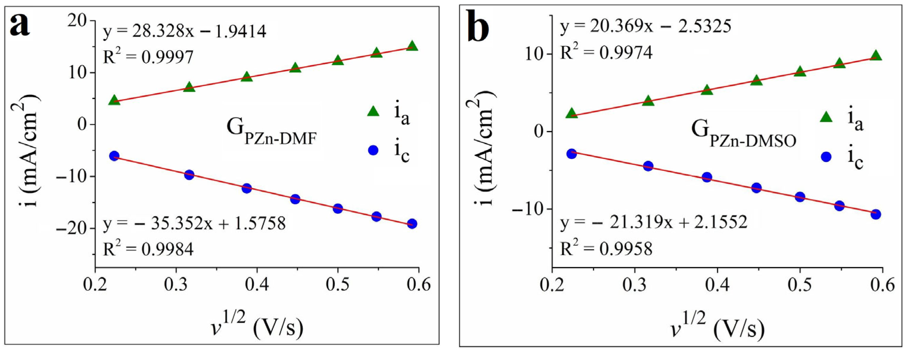
Graphical representations of the anodic and cathodic peak current densities vs. the square root of the scan rate were obtained for the two Zn(II)-porphyrin-modified specimens using the data from the cyclic voltammograms (Figure 3). For both samples—GPZn-DMF (Figure 3a) and GPZn-DMSO (Figure 3b)—the absolute values of the anodic and cathodic peak current densities (ia and ic) increase with the scan rate. This result is indicative of a diffusion-controlled electron transfer process [50].
The OER kinetics at the interface between the acidic medium and the GPZn-DMSO electrode were also investigated. The Tafel plot is presented in Figure 4a and was obtained using i values normalized by the EASA value (iEASA). The Tafel slope value of 135 mV/dec (R2 = 0.9954) indicates the relatively sluggish kinetics of the OER. However, this was not unexpected, since the literature contains OER studies on metalloporphyrin-modified electrodes in which even higher Tafel slopes have been determined [16].
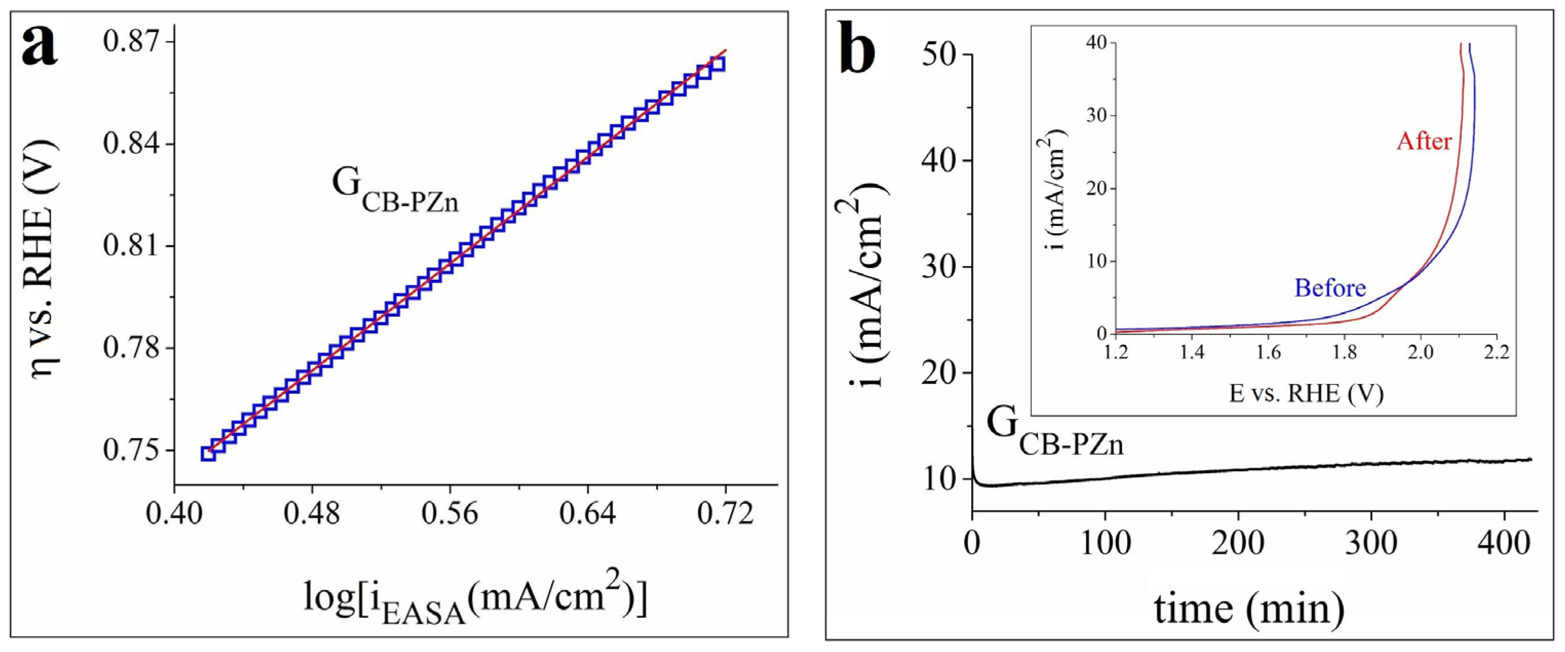
The electrochemical stability of the modified sample was evaluated using chronoamperometry, and the obtained current density vs. time curves are shown in Figure 4b. When the testing was conducted at a constant E value corresponding to i = 10 mA/cm2, the electrode did not exhibit a high degree of stability. However, it was quite stable at the lower E value corresponding to i = 5 mA/cm2. Furthermore, a comparison between the LSVs recorded before and after the latter experiment (Figure 4c) reveals only a small change in the E value corresponding to i = 10 mA/cm2. At this current density, ηOER increased by 12 mV.
The samples manufactured using the first procedure were also evaluated in terms of their HER electrocatalytic activity in the same wide pH range-covering electrolyte solutions employed to outline their OER activity. However, the results in the neutral and strong alkaline media revealed that the activity of the modified electrodes did not surpass that of the unmodified specimen. Also, reproducibility problems were noted in the strong acidic electrolyte, and the investigation was discontinued.
As a general conclusion, the water-splitting studies performed on the electrodes obtained using the first protocol revealed the one most likely to find an application as an OER electrocatalyst.

3.3. SEM and Raman Characterizations of the GPZn-DMSO Electrode

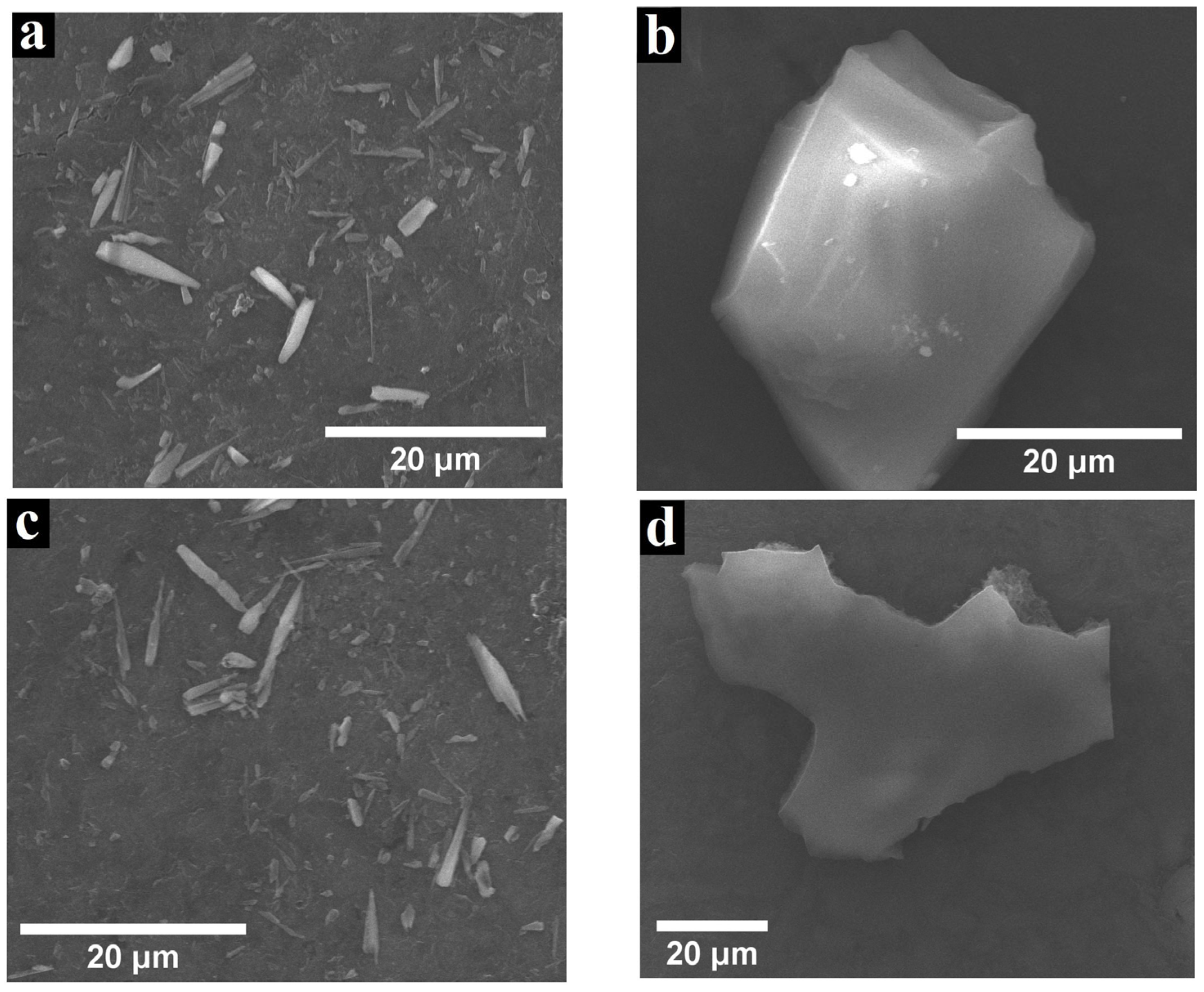
In order to identify the morphological changes that might have occurred during the electrochemical stability evaluation, the surface of the GPZn-DMSO sample was investigated via SEM before and after the experiment, performed at the constant E value corresponding to i = 5 mA/cm2. The recorded images are displayed in Figure 5. Figure 5a,b show micrographs obtained before the test. In the first case, various elongated 2D porphyrin aggregates can be seen, some of which are needle-shaped, while others appear as smaller-sized island-like structures scattered among them. In the second case, a larger island-like metalloporphyrin architecture is evidenced. The images recorded after the experiment (Figure 5c,d) reveal the same needle-like and island-like formations, indicating that the chronoamperometric study did not induce morphological alterations on the surface of the modified electrode.
Interestingly, the types of aggregates identified on the electrode surface during the SEM analysis are not the same as the ones observed during the TEM investigation (revisit Figure 1e). The most likely reasons for this discrepancy are the employed ZnPyTPPP solutions with different concentrations and the distinct substrates. To modify the TEM grid, a 0.15 mM metalloporphyrin solution was utilized, while the surface of the graphite support was changed using a 4 mM solution of the same complex. The smaller concentration was selected to avoid the formation of a Zn(II)-porphyrin layer too thick to allow the electron beam to be transmitted through the sample during the TEM characterization. As for the higher concentration, it was selected because previously reported water electrolysis studies carried out on metalated porphyrin-modified electrodes revealed that higher concentrations lead to more electrocatalytically active electrodes [25]. The dependence between the concentration of the porphyrin and metalloporphyrin solutions on the one hand, and the shapes of the resulting self-assembled aggregates on the other, has been previously reported [51], and so the observed differences are not surprising. However, further SEM analyses were performed to better understand this relationship. Samples consisting of graphite supports coated with the Zn(II)-porphyrin drop-casted in different concentrations from DMSO were prepared and investigated. It was found that the aggregates for the 0.1 mM and 0.2 mM concentrations are very similar in shape to those identified on the TEM sample (Figure 1e), but they are also bigger (having micrometric size). The latter observation may be explained by the difference between the graphite support employed for the SEM study on the one hand and the TEM grid used for the TEM investigation on the other. The recorded micrographs are presented in Figure S4 (see the Supplementary Materials).
The Raman characterization performed on GPZn-DMSO before and after the electrochemical test reveals that the peaks identified on the spectrum recorded on the electrode before the experiment are also present on the one obtained afterward (Figure S5 in the Supplementary Materials).

3.4. Water-Splitting Experiments on the ZnPyTPPP-Based Electrode Obtained with the Second Procedure

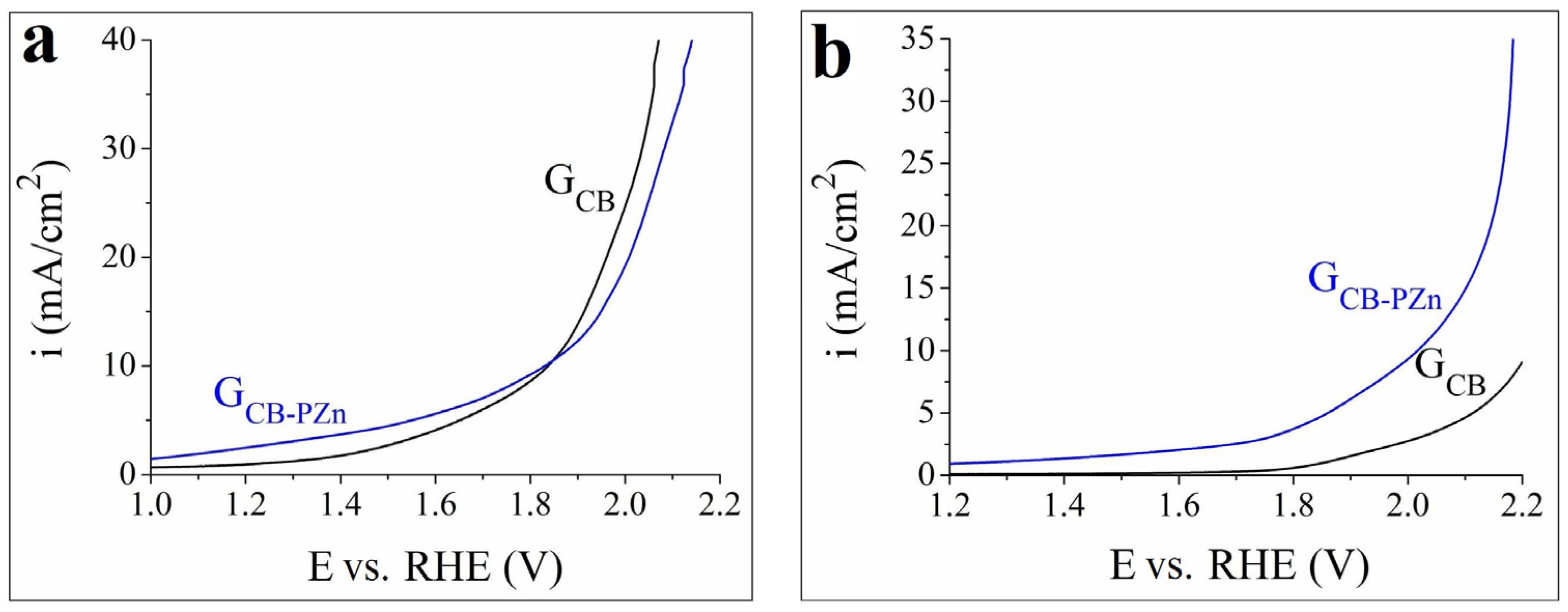
The OER electrocatalytic activity of the GCB-PZn sample, manufactured via the second electrode modification protocol, was analyzed in comparison with the Zn(II)-porphyrin-free GCB specimen acquired by employing a suspension of 10 mg Carbon Black powder, 50 µL Nafion solution, and 450 µL double-distilled water. The data collected in 1 M KOH electrolyte solution revealed that the activity of GCB-PZn is not higher than that of GCB, and so no further investigations were performed in the respective environment. Figure 6 presents the anodic polarization curves recorded in the strong acidic (Figure 6a) and the neutral media (Figure 6b). In the first case, the catalytic activity of the metalloporphyrin-modified electrode is initially higher compared with that of GCB, but the situation is reversed at current density values > 10 mA/cm2. In the second case, the electrode is more active at all current densities. In fact, in the case of GCB and in the studied potential range, the 10 mA/cm2 current density is not even reached. For GCB-PZn, at i = 10 mA/cm2, ηOER = 0.78 V.
The EASA and D values were estimated for both GCB and GCB-PZn. Cyclic voltammograms were recorded under the same conditions as for the GPZn-DMF and GPZn-DMSO samples, and the following results were obtained: EASA = 0.437 ± 0.014 cm2 and D = 8.6 × 10⁻⁵ ± 1.23 × 10⁻⁵ cm2/s for GCB, while for GCB-PZn, EASA = 0.808 ± 0.032 cm2 and D = 5.63 × 10⁻⁵ ± 0.41 × 10⁻⁵ cm2/s. These data reveal the superior electrochemical properties of the Zn(II)-porphyrin-modified electrode.
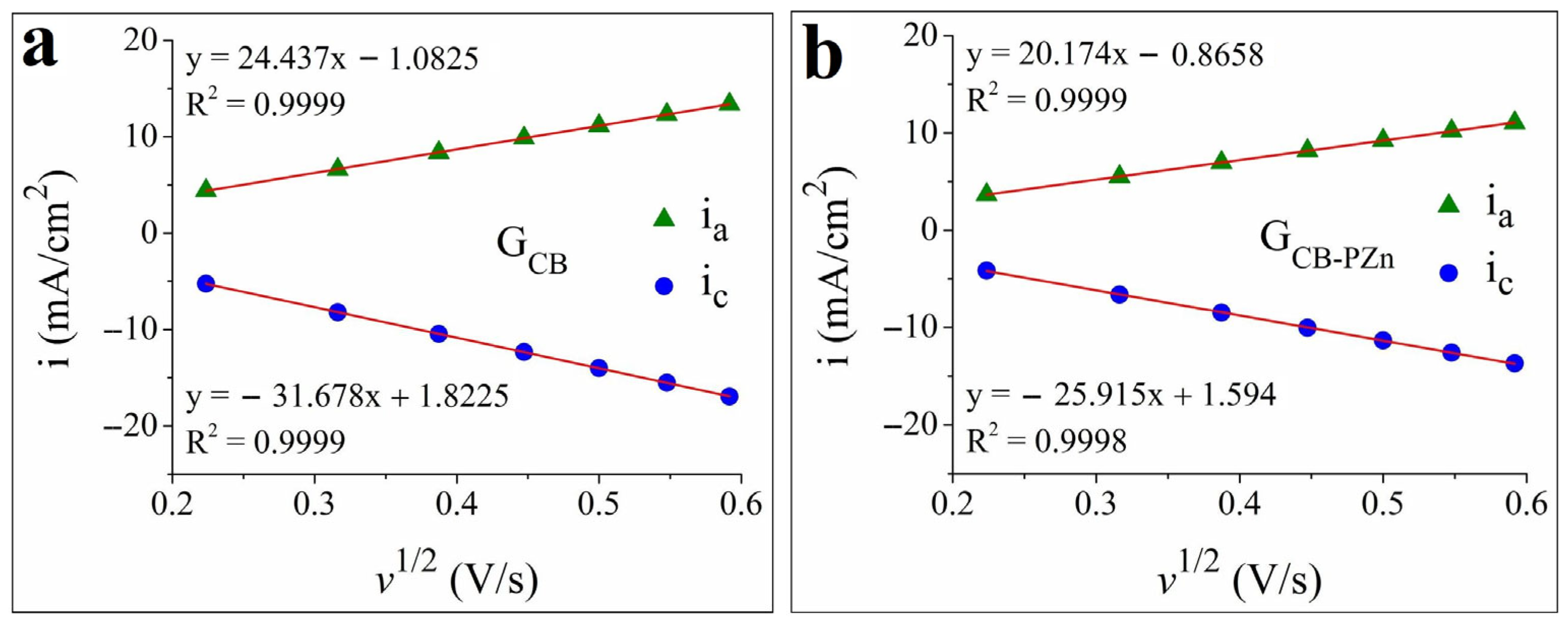
The ia and ic vs. v1/2 graphical depictions for the two electrodes are shown in Figure 7. As was the case with GPZn-DMF and GPZn-DMSO, the absolute ia and ic values of the samples manufactured using the second procedure increase with the scan rate, evidencing that the charge transfer process is controlled by diffusion.
The further study of GCB-PZn focused on the OER kinetics at the interface between the electrode and the neutral electrolyte. The obtained Tafel plot is displayed in Figure 8a, and the determined Tafel slope is 390 mV/dec (R2 = 0.9999). Such sluggish OER kinetics are not unprecedented in the case of porphyrin-based electrodes immersed in a neutral medium [26].
The chronoamperometric experiment performed to outline the stability of the metalloporphyrin-modified electrode lasted for 7 h and was carried out at a constant E value corresponding to i = 10 mA/cm2. As can be seen from the shape of the recorded curve (Figure 8b), the electrode exhibited a fairly high degree of stability. The inset in Figure 8b shows the LSVs obtained before and after the test. At i = 10 mA/cm2, ηOER increased by just 10 mV. Furthermore, the OER overpotentials became smaller in the higher current density domain.
Turning to the voltammetry experiments aimed at identifying the HER electrocatalytic activity of GCB-PZn, Figure 9a presents the cathodic polarization curves recorded in the neutral electrolyte on this sample and on GCB. Compared with the metal-free electrode, the ZnPyTPPP-modified one displays a smaller ηHER for every current density value at which H2 is evolved. For example, at i = −10 mA/cm2, ηHER = 1.02 V for GCB-PZn and 1.15 V for GCB. The role of Carbon Black is to enhance the electron transfer at the interface between the electrode surface and the electrolyte solution. The results obtained on the two electrodes indicate that when both materials are present, the contribution of the Zn(II)-porphyrin’s HER electrocatalytic activity leads to the lowering of the overpotential for all investigated current density values. It is worth noting that it has been shown that interfacial charge-transfer processes involving carbon-based materials can benefit from the electron-donor characteristics of porphyrins [52].
The investigation of the HER kinetics at the interface between the Zn(II)-porphyrin-based sample and the neutral medium led to the Tafel plot shown in Figure 9b and a Tafel slope value of 249 mV/dec (R2 = 0.9979). As was the case with the OER kinetics, the HER kinetics are also sluggish. The specified value is comparable to that obtained by Ge et al., who attribute the slow kinetics of both HER and OER to the low ion concentration of the neutral pH electrolyte solution [26]. The same ascription is made by Xu et al. [9], who point out that the OER and HER kinetics are more sluggish in neutral media than in environments with acidic and alkaline pH. In the case of the HER, the kinetics are slowed down due to a supplementary water dissociation step responsible for the energy barrier behind the sluggishness. Low conductivity and a deficiency in hydrogen atoms are characteristic of neutral media, and because of this, only water molecules provide the H+ required for H2 generation. As for the OER kinetics, they are also slow due to the low ion concentration in neutral environments, but this situation is made worse by the fact that OER is a complex, four-electron, energetically “uphill” reaction [9,53]. In other words, even though both half-cell reactions are sluggish in neutral media, the OER is even slower than the HER, and this is in agreement with the experimental results obtained for the GCB-PZn electrode studied in 0.1 M KCl electrolyte solution.
Lastly, the electrochemical stability of GCB-PZn was investigated at the constant E value corresponding to i = −10 mA/cm2. The recorded chronoamperogram is rendered in Figure 9c, and it indicates the sample’s relatively high degree of stability. Cathodic LSVs recorded before and after the experiment show an increase in the ηHER value at i = −10 mA/cm2 of 20 mV, which is an acceptable change.
The general conclusion reached after carrying out the water-splitting experiments on the ZnPyTPPP-based electrode manufactured via the second procedure described in Section 2.2 is that the sample has the potential to accomplish the decomposition of water in a neutral water electrolyzer in which it serves as both anode and cathode.

3.5. SEM and Raman Characterizations of the GCB-PZn Electrode

The surface of GCB-PZn was analyzed by SEM to outline the morphological modifications that might have occurred due to the electrochemical stability evaluations performed in the neutral electrolyte as part of the OER and HER investigations. The images included in Figure 10 were recorded before the chronoamperometric testing (Figure 10a), after the experiment at the anodic potential corresponding to i = 10 mA/cm2 (Figure 10b), and after the investigation at the cathodic potential corresponding to i = −10 mA/cm2 (Figure 10c). When these scans are compared, no significant morphological changes are observed that could be attributed to testing effects. Since the electrode-manufacturing procedure involved the coating of the graphite support with the metalloporphyrin in powder-based suspension (as opposed to solution), the structures identified during the SEM analysis were powder granules and not self-assembled ZnPyTPPP aggregates.
The SEM characterization was followed by Raman analysis. Spectra were recorded on GCB-PZn, a GCB-PZn sample that was subjected to the anodic electrochemical stability evaluation, and a GCB-PZn sample that was subjected to the cathodic stability evaluation. The results are shown in Figure S6 from the Supplementary Materials, and it can be seen that all the peaks present on the spectrum obtained on the untested electrode are also found on those for the tested specimens. This is not surprising, considering the mild nature characteristic of neutral electrolytes, and it indicates that the chronoamperometric experiments did not induce any significant structural modifications.
To verify if GCB-PZn continues to be fairly stable even at constant E values corresponding to i > 10 mA/cm2 and < −10 mA/cm2, further chronoamperometric tests were performed. The curves shown in Figure S7 (see the Supplementary Materials) are the ones recorded at E values corresponding to i = 15, 20, −15, and −20 mA/cm2. They outline the electrode’s relatively high degree of stability, but since the O2 evolution and H2 evolution are more intense when higher absolute potentials are applied, its effect on the shape of the recorded chronoamperograms is more pronounced.

3.6. Additional Remarks Focusing on the Water-Splitting Electrocatalytic Activity of GPZn-DMSO and GCB-PZn

It has been repeatedly communicated that the metal cation located at the center of the porphyrin macrocycle is also the catalytic center for water electrolysis [16,25,54]. Zn(II)-porphyrins are no exception [17]. In the case of ZnPyTPPP, this center is the Zn2+ cation situated in the Zn-N4 site of the macrocycle.
The experimental data of the current study confirm the literature-based claim regarding the importance of the electrolyte solution’s pH during water splitting [55]. In the case of GPZn-DMSO, the highest electrocatalytic activity was observed for the OER in a strong acidic medium, which provides a high proton concentration but is accompanied by the challenge of decreased operation stability due to the high ηOER values required for the reaction [56]. The difficulty of identifying an electrocatalyst that is both active and stable in such an aggressive environment is reflected in the case of the studied electrode, which is stable only at low current densities. The presence of the pyridyl group as a functional moiety attached to the metalloporphyrin macrocycle contributed to this status, since in a low pH electrolyte, the pyridyl group generates the less stable pyridinium N+H new electrostatic bonds [57]. As a matter of fact, Fagadar et al. reported a study performed in a strong alkaline medium in which the free-base analogue of ZnPyTPPP was used to obtain a graphite-based modified electrode with OER electrocatalytic activity that at i = 10 mA/cm2 exhibited a higher degree of electrochemical stability than GPZn-DMSO [21].
It has been shown that GPZn-DMSO performs better in terms of catalytic activity than GPZn-DMF. This probably has to do with the generating of distinct architectures by the aggregation processes occurring on the surface of the graphite support when the metalloporphyrin is drop-casted from solutions obtained by dissolving it in the different solvents (DMSO and DMF). For example, the structures observed in Figure 1d,e are quite dissimilar. The spherical and quasi-spherical shapes formed when using DMF do not contribute to the water-splitting process with as many catalytically active sites as do the donut-like assemblies evidenced when DMSO is employed as solvent. For one thing, the Zn(II)-porphyrin donut-like aggregates formed on the hydrophobic carbon substrate have a narrower size distribution compared with that of the spherical and quasi-spherical structures. A narrower size distribution implies that there are more catalytically active sites participating in the water splitting and that these are less sterically hindered, being accessible from more than one side. Furthermore, the donut-shaped aggregates with a hole in the middle resemble other porphyrin-based ring-type arrangements that have been reported as being highly active for other catalytic as well as sensing applications due to the non-shielded interaction provided by the steric arrangement [58,59,60]. The steric demand might also have a greater effect than the electronic properties of the substrate [61].
The charge transfer among the metalloporphyrin molecules comprising the arrangements identified for GPZn-DMSO unfolds mostly via π-π interactions, but when the electrode is immersed into an aqueous environment, another non-covalent interaction may be present. Hydrogen bonds are able to form between the functional moieties of adjacent porphyrin molecules via the H2O molecules present in the aqueous electrolyte solution [17]. The ether oxygen atom from the phenoxyphenyl substituents of the ZnPyTPPP porphyrin can lead to the formation of these bonds. Furthermore, due to the difference in electronegativity between the Zn cation located at the M-N4 site of the metalloporphyrin and the C atoms of the carbon support, the former induces an electronegative doping effect on the latter, essentially expediting the interfacial charge transfer during water electrolysis [17].
In the neutral medium, the water-splitting process can be described via the anodic (6) and the cathodic (7) reactions [62]. The electrocatalytic properties of GCB-PZn for overall water splitting in neutral electrolyte are probably the result of the interaction between the conductive support and the composition of the catalyst ink deposited on its surface:
2OH → H2O + 1/2O2 + 2e
2H2O + 2e → H2 + 2OH
This electrode displays a higher EASA compared with GCB, but it is somewhat surprising that the estimated value for the latter specimen is not higher. Even though Carbon Black was used to increase the charge transfer at the electrode/electrolyte interface, higher EASA values were obtained for the Carbon Black-free GPZn-DMF and GPZn-DMSO samples. An explanation for why this is the case involves the organizing of the catalyst ink particles into thick layers on the surface of the graphite substrate during the water-evaporation stage of the electrode manufacturing procedure. Because of these layers, the electrolyte cannot gain access to the pores located in the depth of the deposited catalytic material [63,64], which means fewer catalytically active sites involved in the water electrolysis process and a decreased EASA.
The catalytic activity of GCB-PZn is probably the result of the combined effects of the catalyst ink composition and the graphite substrate, but when it comes to the A3B metalloporphyrin, its properties are partially determined by its mixed meso-substituents [54]. In previously published work by Fagadar et al. [65], another A3B tris-phenoxy-phenyl substituted porphyrin, namely, 5-(4-carboxyphenyl)-5,10,15-tris(4-phenoxyphenyl)-porphyrin, proved to be a selective catalyst for the Knoevenagel condensation of aldehydes, with conversion superior to 98%.
There is interplay between the effect of the pyridyl moiety—a weak electron-withdrawing group [66]—and the three electron-donating phenoxyphenyl substituents. Electron-withdrawing groups diminish the electron density of a porphyrin derivative’s macrocycle, which causes a decrease in the HER overpotential [54,67]. In the case of ZnPyTPPP, the electron-donating effect outweighs the electron-withdrawing one, and as a consequence, the macrocycle’s electron density is increased. This leads to a decrease in the OER overpotential and an increase in ηHER. As observed, ηOER at i = 10 mA/cm2 is smaller than ηHER at i = −10 mA/cm2.
The water electrolysis properties of GCB-PZn were compared with those of other bifunctional water-splitting electrocatalysts in neutral aqueous solutions that were reported in the literature (Table 2). The study most similar to the present one was reported by Ge et al. [26]. The researchers investigated the water electrolysis properties of a metal-free, porphyrin-based covalent organic polymer in a wide pH range and found the material to exhibit bifunctional HER/OER electrocatalytic activity in acidic/alkaline media. It also displayed weaker overall water-splitting activity in neutral buffer solution. The polymer was compared with its zinc-porphyrin-based counterpart, and the results show a substantial decrease in OER activity in the neutral electrolyte. At a potential of 2 V vs. RHE, the current density was <0.25 mA/cm2. Given such a low OER activity, the metalated polymer cannot reasonably be considered as a neutral OER electrocatalyst or, for that matter, a neutral bifunctional electrocatalyst. Contrasting the results of the present work with those of Ge et al., it is observed that GCB-PZn displays higher OER activity and lower but comparable HER activity. When GCB-PZn is compared with other relevant electrodes found in the literature, the porphyrin-based electrode is not as performant. This conclusion emphasizes the need to continue the search for porphyrin derivatives and compositions containing them that possess properties suitable to fulfill the current expectations regarding bifunctional water-splitting electrocatalysts in neutral aqueous solutions.

4. Conclusions

The electrocatalytic water-splitting properties of an asymmetrically substituted A3B Zn(II)-porphyrin were evaluated in aqueous electrolyte solutions covering a wide pH range. Two different procedures were used to manufacture the metalloporphyrin-based electrodes. The most catalytically active electrode obtained with the procedure, in which the porphyrin derivative was solubilized in solvents of different polarities, was identified as the sample formed by modifying the graphite substrate with the catalyst drop-casted from DMSO. In the acidic medium, it exhibited a ηOER value of 0.44 V at i = 10 mA/cm2 and a Tafel slope value of 135 mV/dec. Regarding the second electrode manufacturing procedure, the sample obtained by coating the graphite substrate with a catalyst ink containing the metalloporphyrin displayed electrocatalytic activity for both half-cell reactions involved in water electrolysis. For OER, ηOER = 0.78 V and the Tafel slope = 390 mV/dec. For HER, ηHER = 1.02 V and the Tafel slope = 249 mV/dec. The electrochemical stability test revealed a fairly high degree of stability.
Given the small number of reported bifunctional water-splitting porphyrin-based electrocatalysts in neutral aqueous solutions and the absence from the scientific literature of a zinc-porphyrin-based neutral overall water splitting electrocatalyst, the present work’s contribution to porphyrin chemistry and the water electrolysis domain is constituted by an increase in the current knowledge concerning the applicative potential of porphyrin derivatives.
The microscopy study aimed at characterizing the self-assembly behavior of the Zn(II)-porphyrin deposited on TEM grids from various organic solvents, and performed because porphyrin aggregates contribute to the electrocatalytic activity of metalloporphyrin-modified electrodes, revealed a diversity of architectures stemming from the cooperation among the nonpolar carbon film covering the copper mesh of the TEM grids, the polarities of the solvents used to solubilize the compound, and the properties of its mixed meso-substituents and central metal ion. The results expand the database relevant to the self-assembly of metalloporphyrins.
The article contributes to the ongoing search for a hydrogen-based solution to the global energy crisis and climate change by extending the available knowledge with respect to materials relevant for hydrogen generation through water electrolysis, using a compound metalated with a non-noble metal that is not expensive and is revealed to exhibit electrocatalytic activity.

Supplementary Materials

The following supporting information can be downloaded at: https://www.mdpi.com/article/10.3390/coatings14081048/s1, Figure S1: 1H-NMR spectrum of Zn(II) 5-(4-pyridyl)-10,15,20-tris(4-phenoxyphenyl)-porphyrin recorded in CDCl3 in the chemical shift range in which the main protons resonate; Figure S2: The UV–Vis spectrum of Zn(II) 5-(4-pyridyl)-10,15,20-tris(4-phenoxyphenyl)-porphyrin in THF (c = 1 × 10⁻⁵ M), containing the Soret band and only two Q bands; Figure S3: XRD pattern of Zn(II) 5-(4-pyridyl)-10,15,20-tris(4-phenoxyphenyl)-porphyrin powder sample; Figure S4: SEM micrographs obtained on samples prepared by coating the graphite support with Zn(II) 5-(4-pyridyl)-10,15,20-tris(4-phenoxyphenyl)-porphyrin drop-casted from DMSO. Images (a–c) were recorded on the sample prepared with 0.1 mM metalloporphyrin solution. Images (d–f) were obtained on the sample prepared with 0.2 mM metalloporphyrin solution; Figure S5: Raman spectra recorded on the GPZn-DMSO electrode before the anodic stability test performed in 0.5 M H2SO4 solution at the constant E value corresponding to i = 5 mA/cm2 (GPZn-DMSO a) and after the respective test (GPZn-DMSO b); Figure S6: Raman spectra recorded on GCB-PZn, a GCB-PZn electrode after the anodic stability test (GCB-PZn a), and a GCB-PZn electrode after the cathodic stability test (GCB-PZn c); Figure S7: Chronoamperometric curves recorded on GCB-PZn in 0.1 M KCl solution at constant E values corresponding to i = 15 mA/cm2 (a), 20 mA/cm2 (b), −15 mA/cm2 (c), and −20 mA/cm2 (d). Reference [79] is cited in the supplementary materials.

Author Contributions

Conceptualization, B.-O.T. and E.F.-C.; Data curation, B.-O.T. and F.S.R.; Formal analysis, B.-O.T. and F.S.R.; Funding acquisition, E.F.-C.; Investigation, B.-O.T.; Methodology, B.-O.T. and E.F.-C.; Project administration, F.S.R.; Resources, E.F.-C.; Software, F.S.R.; Supervision, E.F.-C.; Validation, B.-O.T. and E.F.-C.; Visualization, B.-O.T. and F.S.R.; Writing—original draft, B.-O.T.; Writing—review and editing, E.F.-C. All authors have read and agreed to the published version of the manuscript.

Funding

This research received no external funding.

Institutional Review Board Statement

Not applicable.

Informed Consent Statement

Not applicable.

Data Availability Statement

The data supporting the findings of this study are available within the article and Supplementary Materials.

Acknowledgments

The authors would like to thank Paula Sfirloaga and Corina Orha from the National Institute for Research and Development in Electrochemistry and Condensed Matter (Timisoara, Romania), for recording the SEM images, and also the Romanian Academy—Institute of Chemistry “Coriolan Dragulescu”, for supporting the Program 3/2023 of ICT. This work was supported by the Nucleu Program within the National Research Development and Innovation Plan 2022–2027, carried out with the support of MCID, project no. PN 23 27 02 01, contract no. 29N/2023.

Conflicts of Interest

The authors declare no conflicts of interest.

References

  1. Zhang, L.; Jia, C.; Bai, F.; Wang, W.; An, S.; Zhao, K.; Li, Z.; Li, J.; Sun, H. A Comprehensive Review of the Promising Clean Energy Carrier: Hydrogen Production, Transportation, Storage, and Utilization (HPTSU) Technologies. Fuel 2024, 355, 129455. [Google Scholar] [CrossRef]
  2. Aziz, S.K.T.; Awasthi, M.; Guria, S.; Umekar, M.; Karajagi, I.; Riyajuddin, S.K.; Siddhartha, K.V.R.; Saini, A.; Potbhare, A.; Chaudhary, R.G.; et al. Electrochemical Water Splitting by a Bidirectional Electrocatalyst. STAR Protoc. 2023, 4, 102448. [Google Scholar] [CrossRef] [PubMed]
  3. Alex, A.; Petrone, R.; Tala-Ighil, B.; Bozalakov, D.; Vandevelde, L.; Gualous, H. Optimal Techno-Enviro-Economic Analysis of a Hybrid Grid Connected Tidal-Wind-Hydrogen Energy System. Int. J. Hydrogen Energy 2022, 47, 36448–36464. [Google Scholar] [CrossRef]
  4. Solanki, R.; Patra, I.; Ahmad, N.; Kumar, N.B.; Parra, R.M.R.; Zaidi, M.; Yasin, G.; Anil Kumar, T.C.; Hussein, H.A.; Sivaraman, R.; et al. Investigation of Recent Progress in Metal-Based Materials as Catalysts toward Electrochemical Water Splitting. J. Environ. Chem. Eng. 2022, 10, 108207. [Google Scholar] [CrossRef]
  5. Van der Zalm, J.M.; Quintal, J.; Hira, S.A.; Chen, S.; Chen, A. Recent Trends in Electrochemical Catalyst Design for Hydrogen Evolution, Oxygen Evolution, and Overall Water Splitting. Electrochim. Acta 2023, 439, 141715. [Google Scholar] [CrossRef]
  6. Suryanto, B.H.R.; Wang, Y.; Hocking, R.K.; Adamson, W.; Zhao, C. Overall Electrochemical Splitting of Water at the Heterogeneous Interface of Nickel and Iron Oxide. Nat. Commun. 2019, 10, 5599. [Google Scholar] [CrossRef] [PubMed]
  7. Sen, R.; Das, S.; Nath, A.; Maharana, P.; Kar, P.; Verpoort, F.; Liang, P.; Roy, S. Electrocatalytic Water Oxidation: An Overview with an Example of Translation from Lab to Market. Front. Chem. 2022, 10, 861604. [Google Scholar] [CrossRef] [PubMed]
  8. Saad, A.; Gao, Y.; Owusu, K.A.; Liu, W.; Wu, Y.; Ramiere, A.; Guo, H.; Tsiakaras, P.; Cai, X. Ternary Mo2NiB2 as a Superior Bifunctional Electrocatalyst for Overall Water Splitting. Small 2022, 18, 2104303. [Google Scholar] [CrossRef] [PubMed]
  9. Xu, Y.; Wang, C.; Huang, Y.; Fu, J. Recent Advances in Electrocatalysts for Neutral and Large-current-density Water Electrolysis. Nano Energy 2021, 80, 105545. [Google Scholar] [CrossRef]
  10. Liang, Q.; Brocks, G.; Bieberle-Hutter, A. Oxygen evolution reaction (OER) mechanism under alkaline and acidic conditions. J. Phys. Energy 2021, 3, 026001. [Google Scholar] [CrossRef]
  11. Tian, L.; Li, Z.; Song, M.; Li, J. Recent Progress in Water-splitting Electrocatalysis Mediated by 2D Noble Metal Materials. Nanoscale 2021, 13, 12088–12101. [Google Scholar] [CrossRef]
  12. Chakraborty, B.; Beltrán-Suito, R.; Hausmann, J.N.; Garai, S.; Driess, M.; Menezes, P.W. Enabling Iron-Based Highly Effective Electrochemical Water-Splitting and Selective Oxygenation of Organic Substrates Through in Situ Surface Modification of Intermetallic Iron Stannide Precatalyst. Adv. Energy Mater. 2020, 10, 2001377. [Google Scholar] [CrossRef]
  13. Muzammil, A.; Haider, R.; Wei, W.; Wan, Y.; Ishaq, M.; Zahid, M.; Yaseen, W.; Yuan, X. Emerging Transition Metal and Carbon Nanomaterial Hybrids as Electrocatalysts for Water Splitting: A brief review. Mater. Horiz. 2023, 10, 2764–2799. [Google Scholar] [CrossRef]
  14. Quílez-Bermejo, J.; García-Dalí, S.; Karthik, R.; Canevesi, R.; Izquierdo, M.T.; Emo, M.; Celzard, A.; Fierro, V. Zinc Doping Enhances the Electrocatalytic Properties of Cobalt Borides for the Hydrogen Evolution Reaction. Front. Energy Res. 2022, 10, 901395. [Google Scholar] [CrossRef]
  15. Sofianos, V.M.; Lee, J.; Silvester, D.S.; Samanta, P.K.; Paskevicius, M.; English, N.J.; Buckley, C.E. Diverse Morphologies of Zinc Oxide Nanoparticles and their Electrocatalytic Performance in Hydrogen Production. J. Energy Chem. 2021, 56, 162–170. [Google Scholar] [CrossRef]
  16. Taranu, B.O.; Fagadar-Cosma, E. The pH Influence on the Water-splitting Electrocatalytic Activity of Graphite Electrodes Modified with Symmetrically Substituted Metalloporphyrins. Nanomaterials 2022, 12, 3788. [Google Scholar] [CrossRef]
  17. Seo, S.; Lee, K.; Min, M.; Cho, Y.; Kim, M.; Lee, H. A Molecular Approach to an Electrocatalytic Hydrogen Evolution Reaction on Single-layer Graphene. Nanoscale 2017, 9, 3969–3979. [Google Scholar] [CrossRef]
  18. Fagadar-Cosma, E.; Vlascici, D.; Fagadar-Cosma, G. Porfirinele de la Sinteză la Aplicații; Eurostampa: Timisoara, Romania, 2008; ISBN 978-973-687-680-6. [Google Scholar]
  19. Vicente, M.G.H.; Smith, K.M. Syntheses and Functionalizations of Porphyrin Macrocycles. Curr. Org. Synth. 2014, 11, 3–28. [Google Scholar] [CrossRef]
  20. Qian, W.; González-Campo, A.; Pérez-Rodríguez, A.; Rodríguez-Hermida, S.; Imaz, I.; Wurst, K.; Maspoch, D.; Ruiz, E.; Ocal, C.; Barrena, E.; et al. Boosting Self-Assembly Diversity in the Solid-State by Chiral/Non-chiral ZnII-Porphyrin Crystallization. Chem.-Eur. J. 2018, 24, 12950–12960. [Google Scholar] [CrossRef] [PubMed]
  21. Taranu, B.O.; Fagadar-Cosma, E. Catalytic Properties of Free-base Porphyrin Modified Graphite Electrodes for Electrochemical Water Splitting in Alkaline Medium. Processes 2022, 10, 611. [Google Scholar] [CrossRef]
  22. Shi, Y.; Zhang, F.; Linhardt, R.J. Porphyrin-Based Compounds and Their Applications in Materials and Medicine. Dyes Pigments 2021, 188, 109136. [Google Scholar] [CrossRef]
  23. Yao, B.; He, Y.; Wang, S.; Sun, H.; Liu, X. Recent Advances in Porphyrin-Based Systems for Electrochemical Oxygen Evolution Reaction. Int. J. Mol. Sci. 2022, 23, 6036. [Google Scholar] [CrossRef]
  24. Kellett, R.M.; Spiro, T.G. Cobalt(I) Porphyrin Catalysis of Hydrogen Production from Water. Inorg. Chem. 1985, 24, 2373–2377. [Google Scholar] [CrossRef]
  25. Fratilescu, I.; Lascu, A.; Taranu, B.O.; Epuran, C.; Birdeanu, M.; Macsim, A.-M.; Tanasa, E.; Vasile, E.; Fagadar-Cosma, E. One A3B Porphyrin Structure—Three Successful Applications. Nanomaterials 2022, 12, 1930. [Google Scholar] [CrossRef]
  26. Ge, Y.; Lyu, Z.; Marcos-Hernández, M.; Villagrán, D. Free-Base Porphyrin Polymer for Bifunctional Electrochemical Water Splitting. Chem. Sci. 2022, 13, 8597–8604. [Google Scholar] [CrossRef]
  27. Chang, J.; Lv, Q.; Li, G.; Ge, J.; Liu, C.; Xing, W. Core-Shell Structured Ni12P5/Ni3(PO4)2 Hollow Spheres as Difunctional and Efficient Electrocatalysts for Overall Water Electrolysis. Appl. Catal. B Environ. 2017, 204, 486–496. [Google Scholar] [CrossRef]
  28. Sakamaki, A.; Yoshida-Hirahara, M.; Ogihara, H.; Kurokawa, H. One-Step Synthesis of Highly Active NiFe Electrocatalysts for the Oxygen Evolution Reaction. Langmuir 2022, 38, 5525–5531. [Google Scholar] [CrossRef]
  29. Karki, S.B.; Andriotis, A.N.; Menon, M.; Ramezanipour, F. Bifunctional Water-Splitting Electrocatalysis Achieved by Defect Order in LaA2Fe3O8 (A = Ca, Sr). ACS Appl. Energy Mater. 2021, 4, 12063–12066. [Google Scholar] [CrossRef]
  30. Morales Vásquez, M.A.; Suárez, S.A.; Doctorovich, F. Gold and Silver Anchored Cobalt Porphyrins Used for Catalytic Water Splitting. Mater. Chem. Phys. 2015, 159, 159–166. [Google Scholar] [CrossRef]
  31. Fagadar-Cosma, E.; Fagadar-Cosma, G.; Vasile, M.; Enache, C. Synthesis, Spectroscopic and Self-assembling Characterization of Novel Photoactive Mixed Aryl-substituted Porphyrin. Curr. Org. Chem. 2012, 16, 931–941. [Google Scholar] [CrossRef]
  32. Palade, A. Cromofori de Tip Porfirine si Complecsii lor cu Metale Tranzitionale. Elaborarea de Noi Senzori cu Aplicabilitate in Medicina, Chimie si Chimia Mediului. Ph.D. Thesis, Institute of Chemistry Timisoara of Romanian Academy, Timisoara, Romania, 27 October 2017. [Google Scholar]
  33. Lascu, A.; Birdeanu, M.; Fringu, I.; Palade, A.; Bîrdeanu, A.V.; Vaida, M.; Fagadar-Cosma, E. Comparative Optical Study of the Effect Produced by Amine Heterocycles as Axial Ligands for Zn-Porphyrin. In Proceedings of the 9th International Conference on Nanomaterials-Research & Application, Brno, Czech Republic, 18–20 October 2017; pp. 410–415, ISBN 978-80-87294-81-9. [Google Scholar]
  34. Snyder, L.R.; Kirkland, J.J.; Glajch, J.L. Practical HPLC Method Development, 2nd ed.; John Wiley & Sons, Inc.: Hoboken, NJ, USA, 1997; Volume 3, pp. 721–728. ISBN 978-0-471-00703-6. [Google Scholar]
  35. Li, G.; Wang, B.; Resasco, D.E. Solvent Effects on Catalytic Reactions and Related Phenomena at Liquid-Solid Interfaces. Surf. Sci. Rep. 2021, 76, 100541. [Google Scholar] [CrossRef]
  36. Garain, S.; Van, C.D.; Choi, S.; Dang, T.N.; Ager, J.W.; Nam, K.T.; Shin, H.; Lee, M.H. Hierarchical Thiospinel NiCo2S4/Polyaniline Hybrid Nanostructures as a Bifunctional Electrocatalyst for Highly Efficient and Durable Overall Water Splitting. Adv. Mater. Interfaces 2022, 9, 2200649. [Google Scholar] [CrossRef]
  37. Bilal, M.; Altaf, A.; Bint-E-Khalid, E.; Zafar, H.K.; Tahir, N.; Nafady, A.; Wahab, A.; Shah, S.S.A.; Najam, T.; Sohail, M. NiCo2O4 Nano-Needles as an Efficient Electro-Catalyst for Simultaneous Water Splitting and Dye Degradation. RSC Adv. 2023, 13, 23547–23557. [Google Scholar] [CrossRef]
  38. Raveendran, A.; Chandran, M.; Dhanusuraman, R. A Comprehensive Review on the Electrochemical Parameters and Recent Material Development of Electrochemical Water Splitting Electrocatalysts. RSC Adv. 2023, 13, 3843–3876. [Google Scholar] [CrossRef]
  39. Theerthagiri, J.; Sudha, R.; Premnath, K.; Arunachalam, P.; Madhavan, J.; Al-Mayouf, A.M. Growth of Iron Diselenide Nanorods on Graphene Oxide Nanosheets as Advanced Electrocatalyst for Hydrogen Evolution Reaction. Int. J. Hydrogen Energy 2017, 42, 13020–13030. [Google Scholar] [CrossRef]
  40. Ilinoiu, E.C.; Manea, F.; Serra, P.A.; Pode, R. Simultaneous/Selective Detection of Dopamine and Ascorbic Acid at Synthetic Zeolite-Modified/Graphite-Epoxy Composite Macro/Quasi-Microelectrodes. Sensors 2013, 13, 7296–7307. [Google Scholar] [CrossRef]
  41. Konopka, S.J.; McDuffie, B. Diffusion Coefficients of Ferri- and Ferrocyanide Ions in Aqueous Media, Using Twin-Electrode Thin-Layer Electrochemistry. Anal. Chem. 1970, 42, 1741–1746. [Google Scholar] [CrossRef]
  42. Lensen, M.C.; Takazawa, K.; Elemans, J.A.A.W.; Jeukens, C.R.L.P.N.; Christianen, P.C.M.; Maan, J.C.; Rowan, A.E.; Nolte, R.J. Aided Self-Assembly of Porphyrin Nanoaggregates into Ring-Shaped Architectures. Chem.-Eur. J. 2004, 10, 831–839. [Google Scholar] [CrossRef] [PubMed]
  43. Jeukens, C.R.L.P.N.; Lensen, M.C.; Wijnen, F.J.P.; Elemans, J.A.A.W.; Christianen, P.C.M.; Rowan, A.E.; Gerritsen, J.W.; Nolte, R.J.M.; Maan, J.C. Polarized Absorption and Emission of Ordered Self-Assembled Porphyrin Rings. Nano Lett. 2004, 4, 1401–1406. [Google Scholar] [CrossRef]
  44. Cosma, E.F.; Lascu, A.; Shova, S.; Zaltariov, M.F.; Birdeanu, M.; Croitor, L.; Balan, A.; Anghel, D.; Stamatin, S. X-Ray Structure Elucidation of a Pt-Metalloporphyrin and Its Application for Obtaining Sensitive AuNps-Plasmonic Hybrids Capable of Detecting Triiodide Anions. Int. J. Mol. Sci. 2019, 20, 710. [Google Scholar] [CrossRef]
  45. Bahrami, M.; Kraft, S.; Becker, J.; Hartmann, H.; Vogler, B.; Wardelmann, K.; Behle, H.; Elemans, J.A.A.W.; Barke, I.; Speller, S. Correlative Microscopy of Morphology and Luminescence of Cu Porphyrin Aggregates. J. Phys. B At. Mol. Opt. Phys. 2018, 51, 144002. [Google Scholar] [CrossRef]
  46. Menezes, P.W.; Panda, C.; Loos, S.; Bunschei-Bruns, F.; Walter, C.; Schwarze, M.; Deng, X.; Dau, H.; Driess, M. A Structurally Versatile Nickel Phosphite Acting as a Robust Bifunctional Electrocatalyst for Overall Water Splitting. Energy Environ. Sci. 2018, 11, 1287–1298. [Google Scholar] [CrossRef]
  47. Mani, V.; Anantharaj, S.; Mishra, S.; Kalaiselvi, N.; Kundu, S. Iron Hydroxyphosphate and Sn-Incorporated Iron Hydroxyphosphate: Efficient and Stable Electrocatalysts for Oxygen Evolution Reaction. Catal. Sci. Technol. 2017, 7, 5092–5104. [Google Scholar] [CrossRef]
  48. Li, J.; Li, J.; Zhou, X.; Xia, Z.; Gao, W.; Ma, Y.; Qu, Y. Highly Efficient and Robust Nickel Phosphides as Bifunctional Electrocatalysts for Overall Water-Splitting. ACS Appl. Mater. Interfaces 2016, 8, 10826–10834. [Google Scholar] [CrossRef] [PubMed]
  49. Zhou, Z.; Zaman, W.Q.; Sun, W.; Cao, L.M.; Tariq, M.; Yang, J. Cultivating Crystal Lattice Distortion in IrO2: Via Coupling with MnO2 to Boost the Oxygen Evolution Reaction with High Intrinsic Activity. Chem. Commun. 2018, 54, 4959–4962. [Google Scholar] [CrossRef]
  50. Shrivastav, V.; Dubey, M.P.; Shrivastav, V.; Kaur, A.; Hołdyński, M.; Krawczyńska, A.; Tiwari, U.K.; Deep, A.; Nogala, W.; Sundriyal, S. Diffusion Controlled Electrochemical Analysis of MoS2 and MOF Derived Metal Oxide–Carbon Hybrids for High Performance Supercapacitors. Sci. Rep. 2023, 13, 20675. [Google Scholar] [CrossRef]
  51. Taranu, B.-O. Contribuții la Caracterizarea Fizico-Chimică a Porfirinelor. Aplicații în Senzoristică și Coroziune. Ph.D. Thesis, Institute of Chemistry Timisoara of Romanian Academy, Timisoara, Romania, 19 October 2016. [Google Scholar]
  52. Xu, H.; Wu, P.; Liao, C.; Lv, C.; Gu, Z. Controlling the Morphology and Optoelectronic Properties of Graphene Hybrid Materials by Porphyrin Interactions. ChemComm 2014, 50, 8951–8954. [Google Scholar] [CrossRef]
  53. Zhao, Y.; Yu, Z.; Ge, A.; Liu, L.; Faria, J.L.; Xu, G.; Zhu, M. Direct Seawater Splitting for Hydrogen Production: Recent Advances in Materials Synthesis and Technological Innovation. Green Energy Environ. 2024; in press. [Google Scholar] [CrossRef]
  54. Zhang, W.; Lai, W.; Cao, R. Energy-Related Small Molecule Activation Reactions: Oxygen Reduction and Hydrogen and Oxygen Evolution Reactions Catalyzed by Porphyrin- and Corrole-Based Systems. Chem. Rev. 2017, 117, 3717–3797. [Google Scholar] [CrossRef]
  55. Anantharaj, S.; Aravindan, V. Developments and Perspectives in 3D Transition-Metal-Based Electrocatalysts for Neutral and Near-Neutral Water Electrolysis. Adv. Energy Mater. 2020, 10, 1902666. [Google Scholar] [CrossRef]
  56. Siwal, S.S.; Yang, W.; Zhang, Q. Recent Progress of Precious-Metal-Free Electrocatalysts for Efficient Water Oxidation in Acidic Media. J. Energy Chem. 2020, 51, 113–133. [Google Scholar] [CrossRef]
  57. Kano, K.; Minamizono, H.; Kitae, T.; Negi, S. Self-Aggregation of Cationic Porphyrins in Water. Can π-π Stacking Interaction Overcome Electrostatic Repulsive Force? J. Phys. Chem. A 1997, 101, 6118–6124. [Google Scholar] [CrossRef]
  58. Hiroto, S.; Shinokubo, H.; Osuka, A. Porphyrin Synthesis in Water Provides New Expanded Porphyrins with Direct Bipyrrole Linkages: Isolation and Characterization of Two Heptaphyrins. J. Am. Chem. Soc. 2006, 128, 6568–6569. [Google Scholar] [CrossRef]
  59. Zhang, Z.; Ma, L.; Fang, F.; Hou, Y.; Lu, C.; Mu, C.; Zhang, Y.; Liu, H.; Gao, K.; Wang, M.; et al. Porphyrin-Based Multicomponent Metallacage: Host−Guest Complexation toward Photooxidation-Triggered Reversible Encapsulation and Release. JACS Au 2022, 2, 1479–1487. [Google Scholar] [CrossRef]
  60. Fagadar-Cosma, E.; Vlascici, D.; Fagadar-Cosma, G.; Palade, A.; Lascu, A.; Creanga, I.; Birdeanu, M.; Cristescu, R.; Cernica, I. A Sensitive A3B Porphyrin Nanomaterial for CO2 Detection. Molecules 2014, 19, 21239–21252. [Google Scholar] [CrossRef]
  61. Hiroto, S.; Miyake, Y.; Shinokubo, H. Synthesis and Functionalization of Porphyrins through Organometallic Methodologies. Chem. Rev. 2017, 117, 2910–3043. [Google Scholar] [CrossRef] [PubMed]
  62. Yan, Y.; Xia, B.Y.; Zhao, B.; Wang, X. A Review on Noble-Metal-Free Bifunctional Heterogeneous Catalysts for Overall Electrochemical Water Splitting. J. Mater. Chem. A 2016, 4, 17587–17603. [Google Scholar] [CrossRef]
  63. Boshnakova, I.; Lefterova, E.; Slavcheva, E. Investigation of Montmorillonite as Carrier for OER. Int. J. Hydrogen Energy 2018, 43, 16897–16904. [Google Scholar] [CrossRef]
  64. Lahiri, A.; Li, G.; Endres, F. Highly Efficient Electrocatalytic Hydrogen Evolution Reaction on Carbonized Porous Conducting Polymers. J. Solid State Electrochem. 2020, 24, 2763–2771. [Google Scholar] [CrossRef]
  65. Mak, C.A.; Pericas, M.A.; Fagadar-Cosma, E. Functionalization of A3B-type porphyrin with Fe3O4 MNPs. Supramolecular Assemblies, Gas Sensor and Catalytic Applications. Catal. Today 2018, 306, 268–275. [Google Scholar] [CrossRef]
  66. Zhou, S.Q.; Xia, Q.Y.; Kong, L.X.; Ayyanar, K.; Ju, X.H. Theoretical Study of Effects of Anchoring Groups on Photovoltaic Properties of a Triarylamine-Based p-Type Sensitizer. ACS Omega 2020, 5, 23491–23496. [Google Scholar] [CrossRef]
  67. Han, Y.; Fang, H.; Jing, H.; Sun, H.; Lei, H.; Lai, W.; Cao, R. Singly versus Doubly Reduced Nickel Porphyrins for Proton Reduction: Experimental and Theoretical Evidence for a Homolytic Hydrogen-Evolution Reaction. Angew. Chem.-Int. Ed. 2016, 55, 5457–5462. [Google Scholar] [CrossRef] [PubMed]
  68. Li, Z.; Zou, J.; Liang, T.; Song, X.; Li, Z.; Wen, J.; Peng, M.; Zeng, X.; Huang, H.; Wu, H. MOF-Derived Ultrasmall Ru@RuO2 Heterostructures as Bifunctional and pH-Universal Electrocatalysts for 0.79 V Asymmetric Amphoteric Overall Water Splitting. Chem. Eng. J. 2023, 460, 141672. [Google Scholar] [CrossRef]
  69. Ravi, A.; Mulkapuri, S.; Das, S.K. Hydroxylated Polyoxometalate with Cu(II)- and Cu(I)-Aqua Complexes: A Bifunctional Catalyst for Electrocatalytic Water Splitting at Neutral pH. Inorg. Chem. 2023, 62, 12650–12663. [Google Scholar] [CrossRef] [PubMed]
  70. Zhang, D.; Sun, C.; Liu, D.; Song, C.; Wang, D. Space-Confined Ultrafine Co4N Nanodots within an N-Doped Carbon Framework on Carbon Cloth for Highly Efficient Universal pH Overall Water Splitting. Sci. China Mater. 2023, 66, 1362–1372. [Google Scholar] [CrossRef]
  71. Chen, L.; Lu, B.; Zhang, J.; Wu, R.; Guo, Y. Integrating Trace Ruthenium Cluster with Cobalt Boride toward Superior Overall Water Splitting in Neutral Media. J. Colloid Interface Sci. 2022, 623, 897–904. [Google Scholar] [CrossRef] [PubMed]
  72. Chiang, C.H.; Yang, Y.C.; Lin, J.W.; Lin, Y.C.; Chen, P.T.; Dong, C.L.; Lin, H.M.; Chan, K.M.; Kao, Y.T.; Suenaga, K.; et al. Bifunctional Monolayer WSe2/Graphene Self-Stitching Heterojunction Microreactors for Efficient Overall Water Splitting in Neutral Medium. ACS Nano 2022, 16, 18274–18283. [Google Scholar] [CrossRef]
  73. Zhang, B.; Shan, J.; Wang, W.; Tsiakaras, P.; Li, Y. Oxygen Vacancy and Core–Shell Heterojunction Engineering of Anemone-Like CoP@CoOOH Bifunctional Electrocatalyst for Efficient Overall Water Splitting. Small 2022, 18, 2106012. [Google Scholar] [CrossRef]
  74. Jin, W.; Wu, H.; Cai, W.; Jia, B.; Batmunkh, M.; Wu, Z.; Ma, T. Evolution of Interfacial Coupling Interaction of Ni-Ru Species for pH-Universal Water Splitting. Chem. Eng. J. 2021, 426, 130762. [Google Scholar] [CrossRef]
  75. Liu, L.; Yang, X.; Zhao, Y.; Yao, B.; Hou, Y.; Fu, W. The Rational Design of Cu2−XSe@(Co,Cu)Se2 core-Shell Structures as Bifunctional Electrocatalysts for Neutral-pH Overall Water Splitting. Nanoscale 2021, 13, 1134–1143. [Google Scholar] [CrossRef]
  76. Yang, Y.; Yao, H.; Yu, Z.; Islam, S.M.; He, H.; Yuan, M.; Yue, Y.; Xu, K.; Hao, W.; Sun, G.; et al. Hierarchical Nanoassembly of MoS2/Co9S8/Ni3S2/Ni as a Highly Efficient Electrocatalyst for Overall Water Splitting in a Wide pH Range. J. Am. Chem. Soc. 2019, 141, 10417–10430. [Google Scholar] [CrossRef]
  77. Li, K.; Zhang, J.; Wu, R.; Yu, Y.; Zhang, B. Anchoring CoO Domains on CoSe2 Nanobelts as Bifunctional Electrocatalysts for Overall Water Splitting in Neutral Media. Adv. Sci. 2015, 3, 1500426. [Google Scholar] [CrossRef] [PubMed]
  78. Zhang, Z.; Hao, J.; Yang, W.; Tang, J. Iron Triad (Fe, Co, Ni) Trinary Phosphide Nanosheet Arrays as High-Performance Bifunctional Electrodes for Full Water Splitting in Basic and Neutral Conditions. RSC Adv. 2016, 6, 9647–9655. [Google Scholar] [CrossRef]
  79. Chen, L.; Li, J. A Study of γ-Fe2O3 Nanoparticles Modified Using ZnCl2 during Synthesis. Adv. Mater. Phys. Chem. 2013, 3, 31–35. [Google Scholar] [CrossRef]
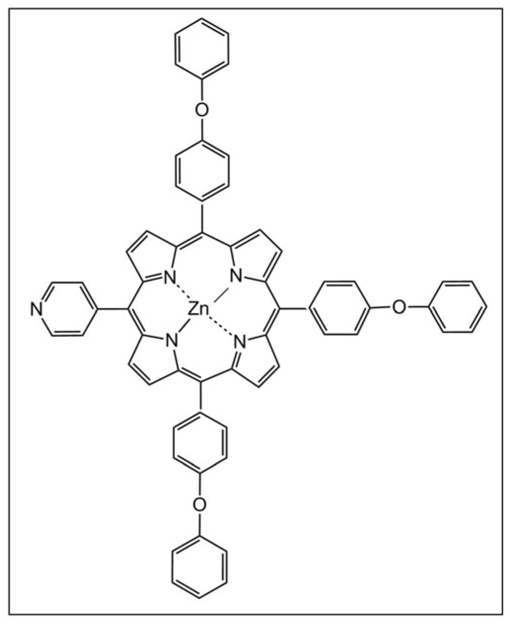
Scheme 1. Chemical structure of Zn(II) 5-(4-pyridyl)-10,15,20-tris(4-phenoxyphenyl)-porphyrin.
Coatings 14 01048 sch001
Figure 1. STEM images recorded on specimens prepared by applying ZnPyTPPP from DCM (a), THF (b), PhCN (c), DMF (d), and DMSO (e). The insets in (ac,e) present STEM and TEM images collected at higher magnification.
Coatings 14 01048 g001
Figure 2. LSVs obtained during OER experiments on the G0, GPZn-DCM, GPZn-THF, GPZn-PhCN, GPZn-DMF, and GPZn-DMSO electrodes immersed in 1 M KOH (a), 0.1 M KCl (b), and 0.5 M H2SO4 (c) electrolyte solutions at v = 5 mV/s and ηOER bar column graphs measured at i = 10 mA/cm2 for the alkaline (d), neutral (e), and acidic (f) media.
Coatings 14 01048 g002
Figure 3. Graphical representations of ia and ic vs. v1/2 for GPZn-DMF (a) and GPZn-DMSO (b).
Coatings 14 01048 g003
Figure 4. (a) The Tafel plot for the GPZn-DMSO electrode in 0.5 M H2SO4 solution. (b) Chronoamperometric curves recorded on GPZn-DMSO electrodes, in 0.5 M H2SO4 solution, at constant E values corresponding to i = 10 mA/cm2 and i = 5 mA/cm2, respectively. (c) The LSVs obtained on the GPZn-DMSO electrode before and after the electrochemical stability test performed at the constant potential corresponding to i = 5 mA/cm2 (0.5 M H2SO4 solution and v = 5 mV/s).
Coatings 14 01048 g004
Figure 5. SEM micrographs obtained on the GPZn-DMSO electrode: (a,b) before the chronoamperometric stability experiment and (c,d) after the test.
Coatings 14 01048 g005
Figure 6. LSVs obtained during OER experiments on the GCB and GCB-PZn electrodes immersed in 0.5 M H2SO4 (a) and in 0.1 M KCl (b) electrolyte solutions at v = 5 mV/s.
Coatings 14 01048 g006
Figure 7. Graphical representations of ia and ic vs. v1/2 for GCB (a) and GCB-PZn (b).
Coatings 14 01048 g007
Figure 8. (a) The Tafel plot for the GCB-PZn electrode in 0.1 M KCl solution. (b) Chronoamperometric curve recorded on GCB-PZn in 0.1 M KCl solution and inset with the LSVs obtained on the same electrode before and after the electrochemical stability test (0.1 M KCl solution and v = 5 mV/s).
Coatings 14 01048 g008
Figure 9. (a) LSVs obtained during HER experiments on the GCB and GCB-PZn electrodes immersed in 0.1 M KCl electrolyte solution at v = 5 mV/s. (b) The Tafel plot for GCB-PZn in 0.1 M KCl solution. (c) Chronoamperometric curve recorded on GCB-PZn in 0.1 M KCl solution and inset with the LSVs obtained on the same electrode before and after the electrochemical stability test.
Coatings 14 01048 g009
Figure 10. SEM images recorded on GCB-PZn electrodes before any electrochemical testing (a), after testing at constant anodic potential (b), and after testing at constant cathodic potential (c).
Coatings 14 01048 g010
Table 1. The names of ZnPyTPPP-modified electrodes.
Electrode nameG0GPZn-DCMGPZn-THFGPZn-PhCNGPZn-DMFGPZn-DMSO
Solvent-DCMTHFPhCNDMFDMSO
Table 2. Comparative presentations of OER and HER activities for GCB-PZn and for other reported electrodes containing bifunctional water-splitting electrocatalysts in neutral aqueous electrolyte solutions.
ElectrocatalystElectrolyteηOER (V) at
i = 10 mA/cm2
OER Tafel Slope (V/dec)ηHER (V) at
i = −10 mA/cm2
HER Tafel
Slope (V/dec)
Ref.
Ultrasmall Ru@RuO2 heterostructures1 M PBS0.263~0.0880.043~0.05[68]
Hydroxylated POM with Cu(II)- and Cu(I)-Aqua
Complex/glassy carbon
0.1 M KCl~0.418 a~0.356~0.443 b~0.314[69]
Co4N nanodots anchored to N-doped C framework1 M PBS0.115~0.0410.076~0.04[70]
Ru-modified
cobalt boride hybrid catalyst/Ni foil
0.5 M PBS0.28~0.1130.056~0.046[71]
Cr-doped WSe2/graphene heterojunction1 M PBS0.520.1130.190.104[72]
CoP@CoOOH core–shell heterojunction
on C paper
1 M PBS0.318~0.1270.089~0.064[73]
NiRu nanoparticles encapsulated into N-doped C1 M PBS0.3160.0890.080.079[74]
Cu2-xSe@(Co,Cu)Se2 core–shell structure1 M PBS0.3960.1020.1060.081[75]
Co9S8/Ni3S2/NF1 M PBS0.4950.2260.330.082[76]
CoO domains on CoSe2 nanobelts/Ti mesh0.5 M PBS0.510.1980.3370.131[77]
Fe10Co40Ni40P1 M PBS0.4660.2460.30.132[78]
Porphvlar-based ink on carbon paper1 M PBS0.67 c0.485~0.77 d0.227[26]
GCB-PZn0.1 M KCl0.78
0.47 c
0.391.02
1.00 d
0.249This work
a at i = 1 mA/cm2; b at i = −1 mA/cm2; c at i = 2.5 mA/cm2; d at i = −7 mA/cm2.
Disclaimer/Publisher’s Note: The statements, opinions and data contained in all publications are solely those of the individual author(s) and contributor(s) and not of MDPI and/or the editor(s). MDPI and/or the editor(s) disclaim responsibility for any injury to people or property resulting from any ideas, methods, instructions or products referred to in the content.