
Influence of Scanning Paths on the Weld Pool Behavior, Microstructure, and Mechanical Property of AA2060 Al-Li Alloy Joints by Laser Beam Oscillation Welding
 , ,
, ,
Abstract
:1. Introduction
2. Experimental Procedures
2.1. Materials
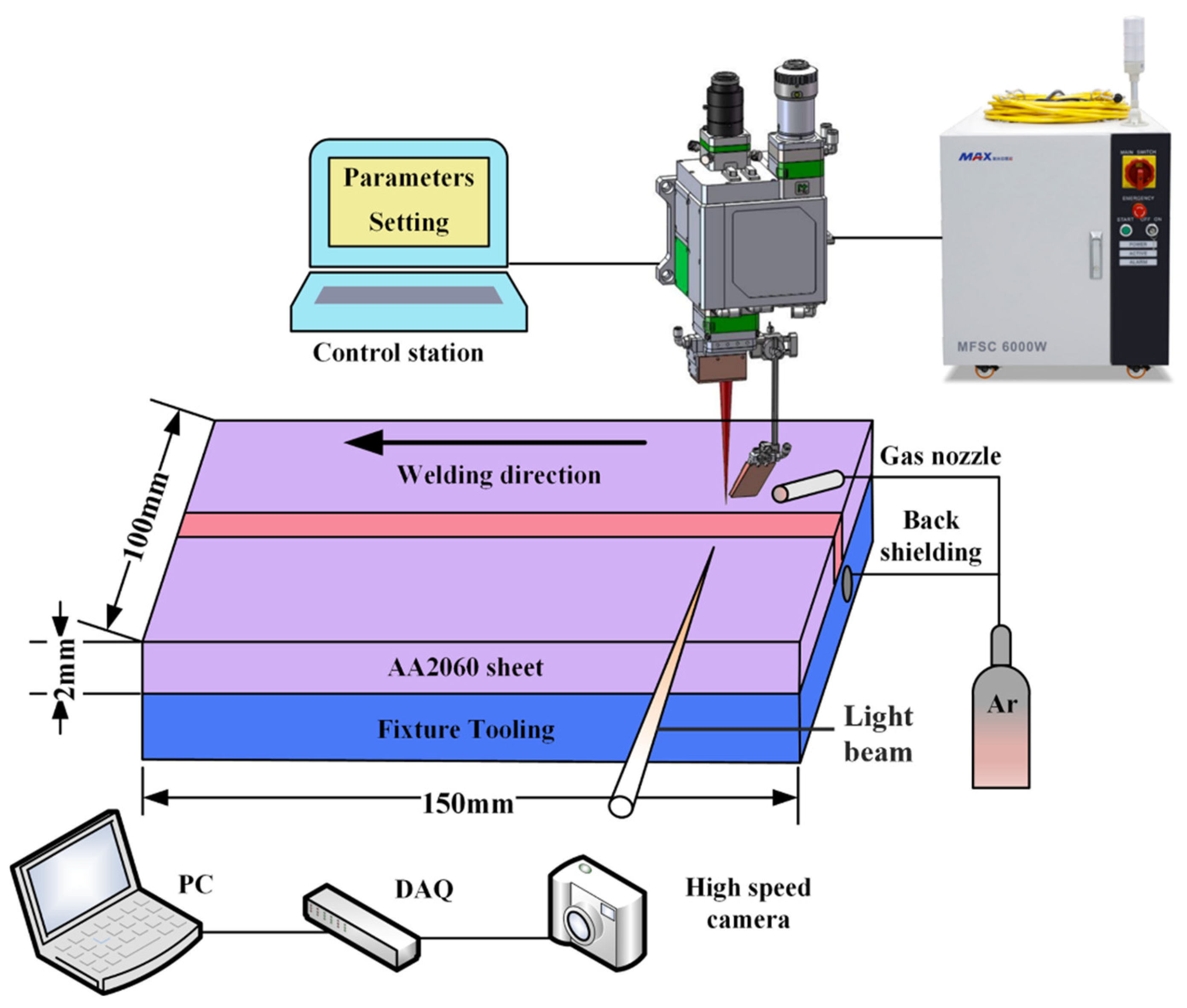
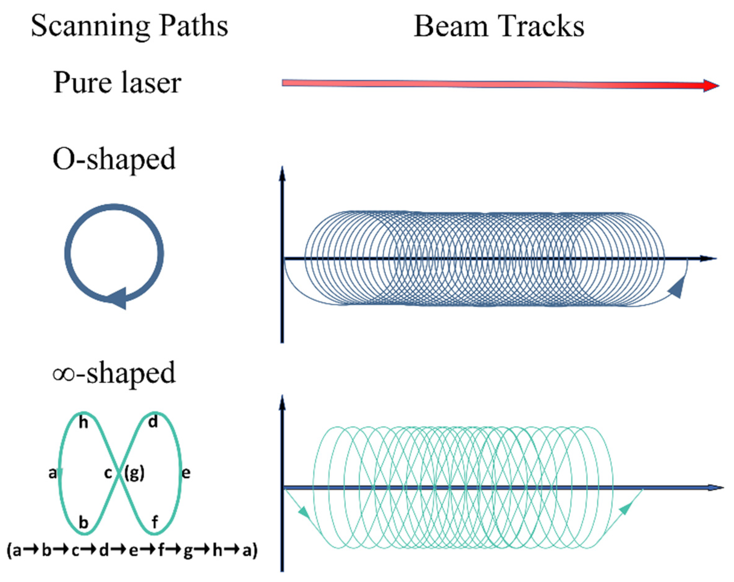
2.2. Equipment and Methods
3. Results and Discussion
3.1. Macrostructure
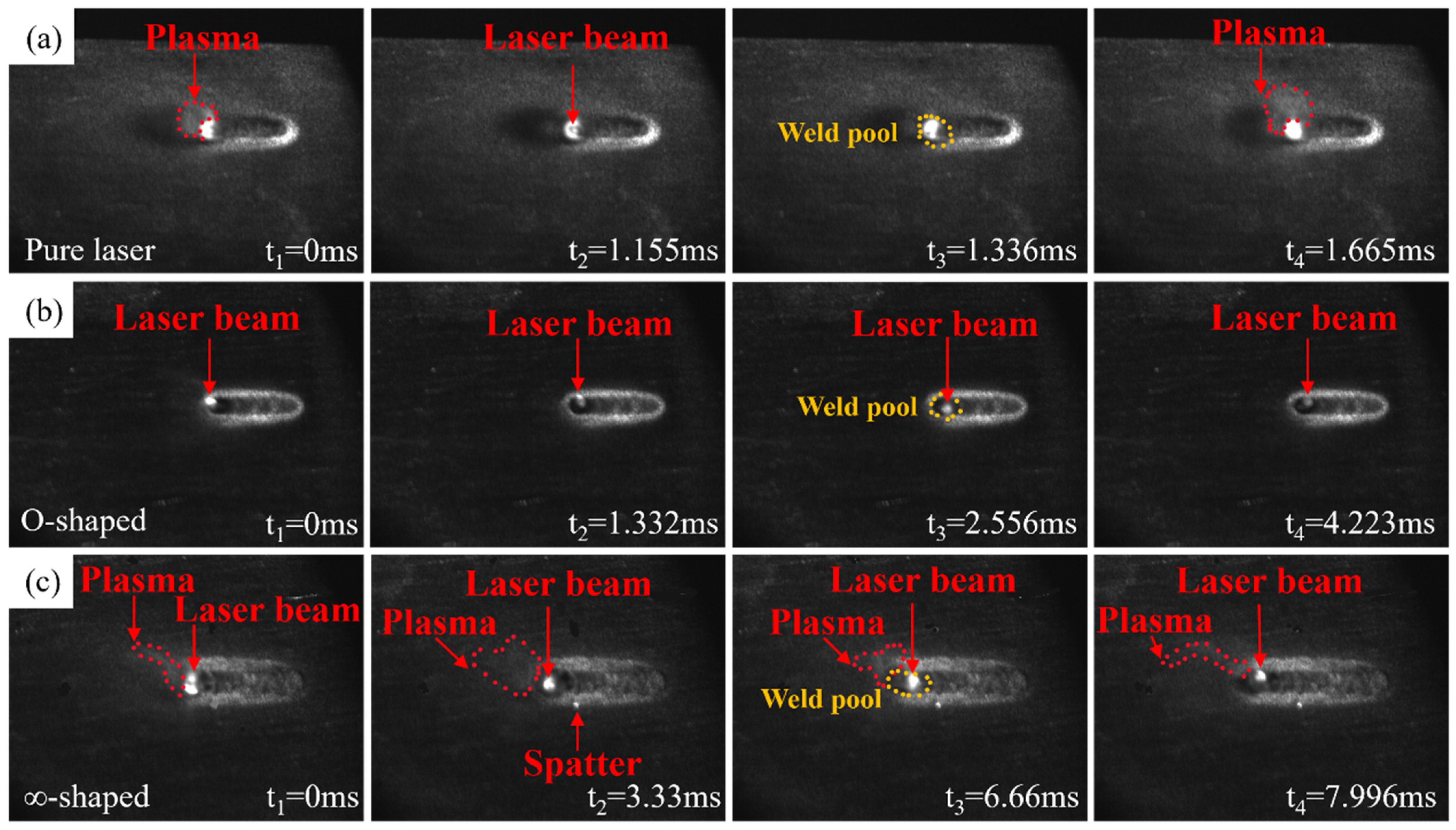
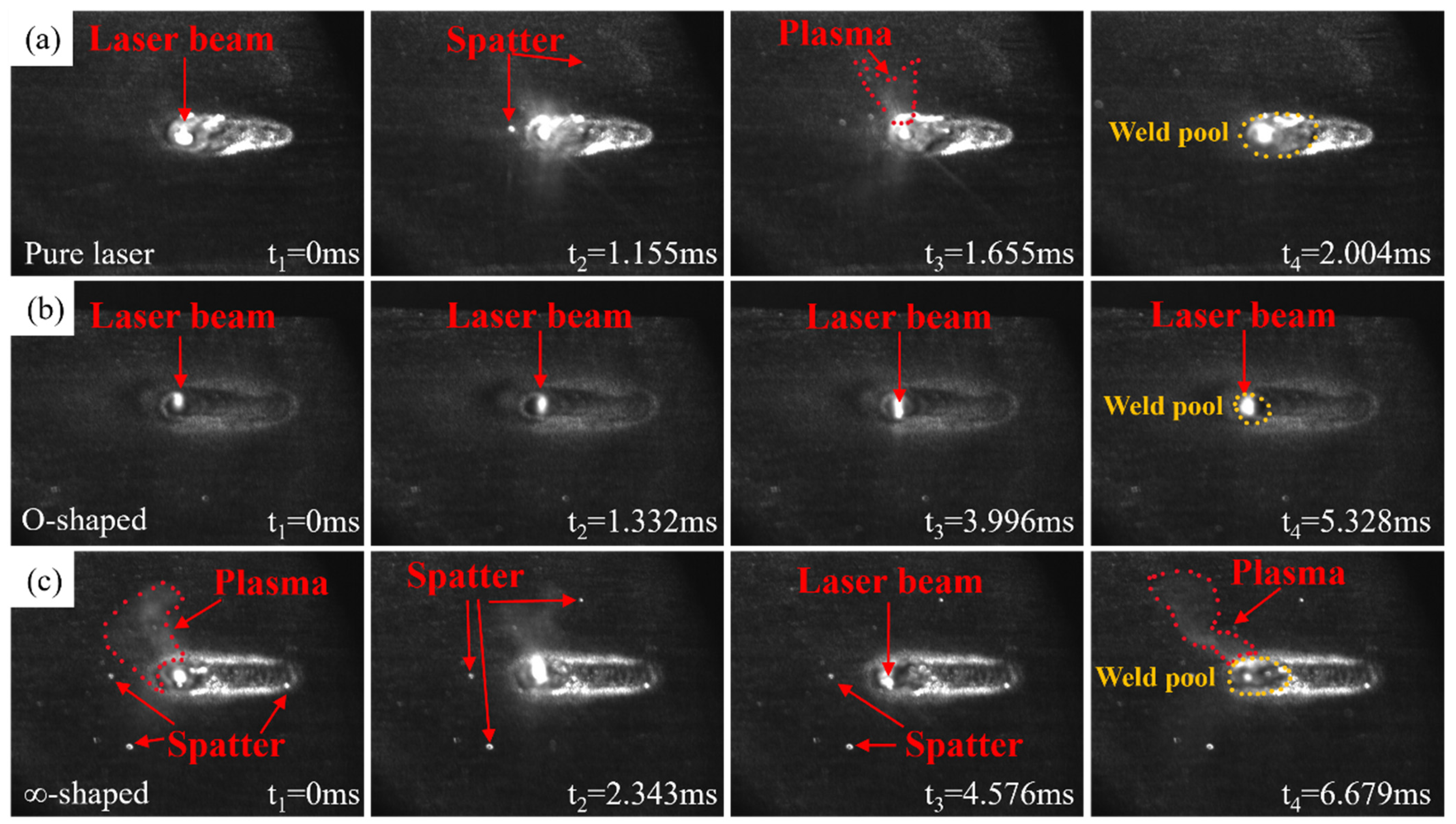
3.2. Weld Pool Behavior
3.3. Microstructure
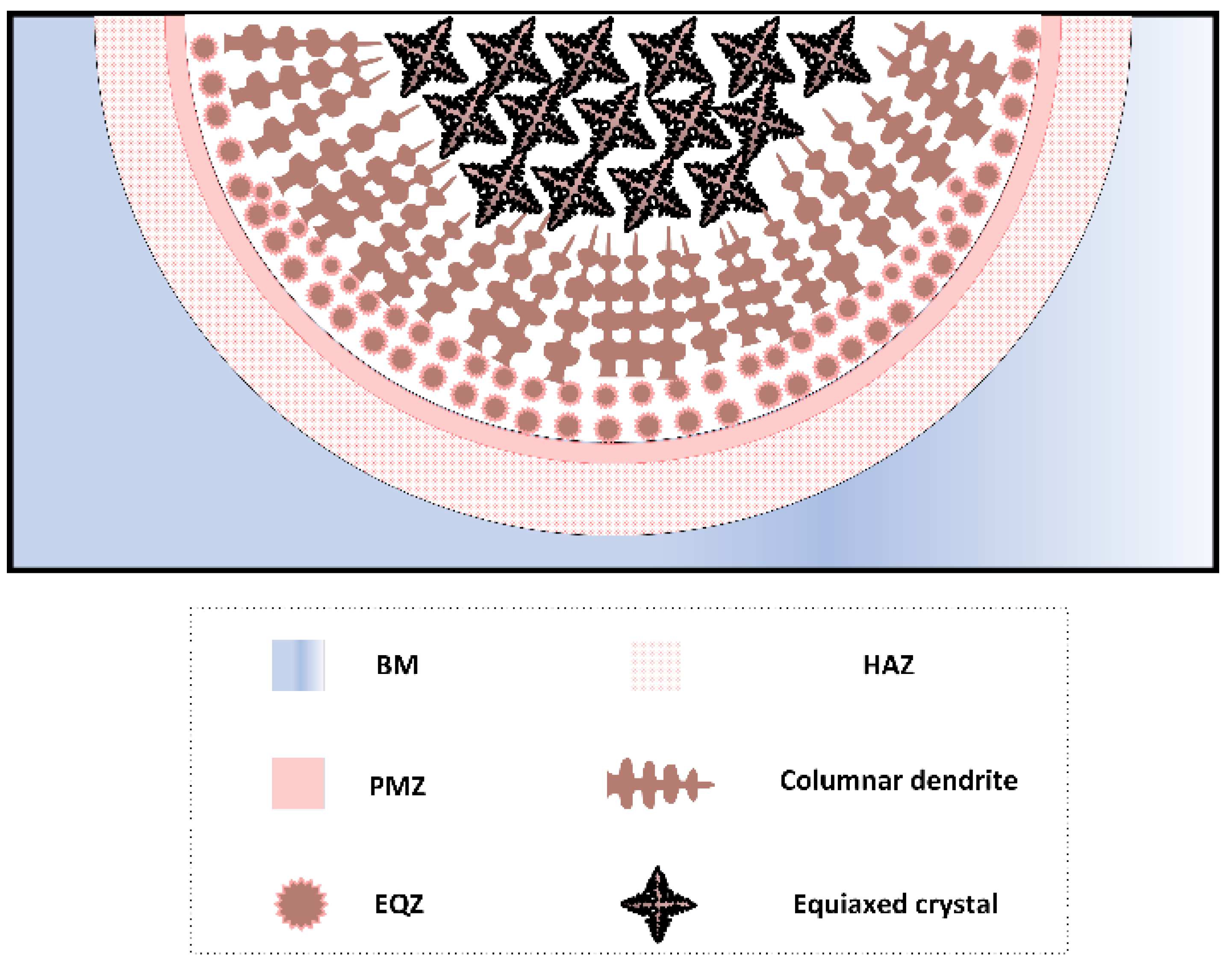
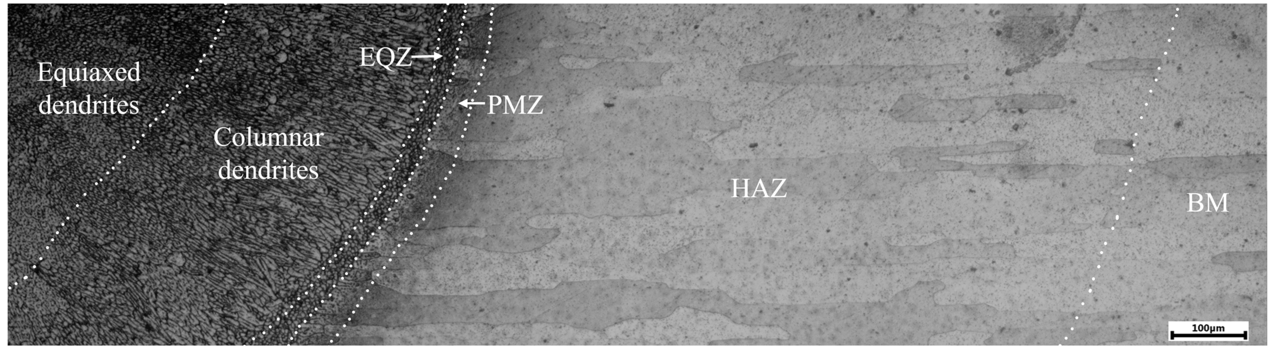
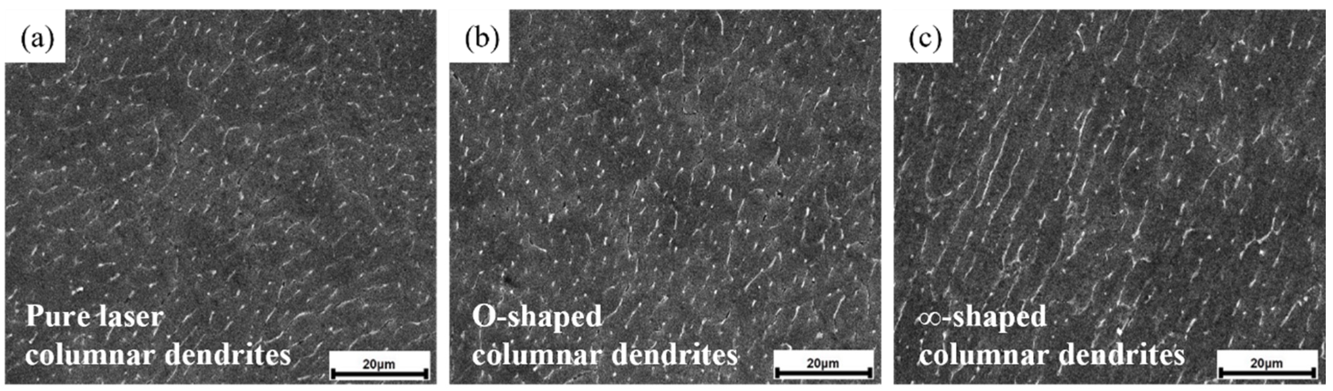
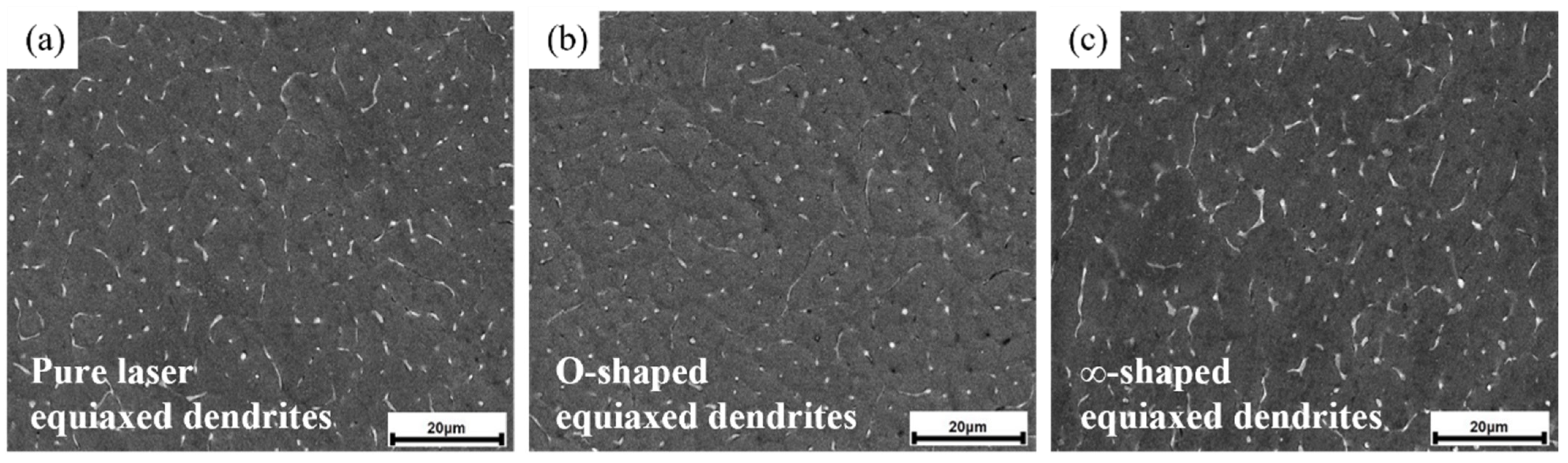
3.3.1. Crystal Morphology
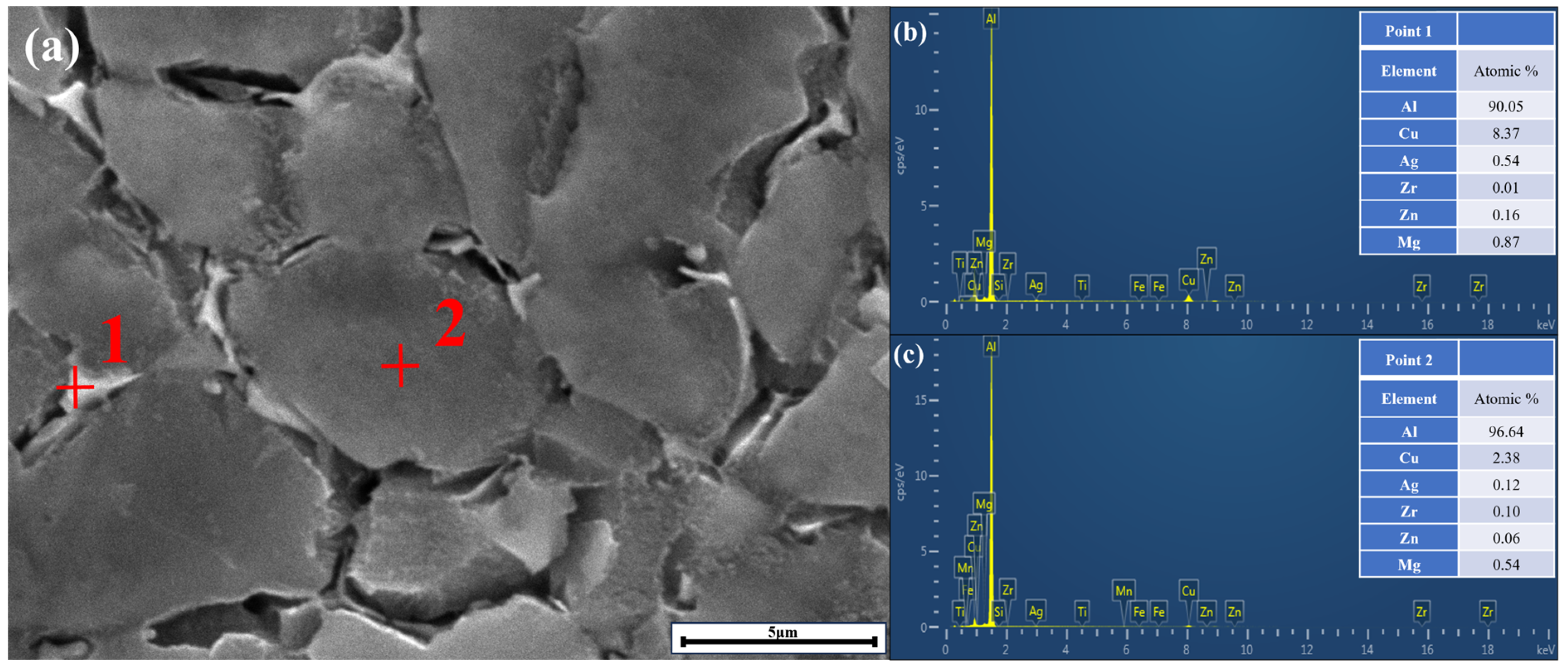
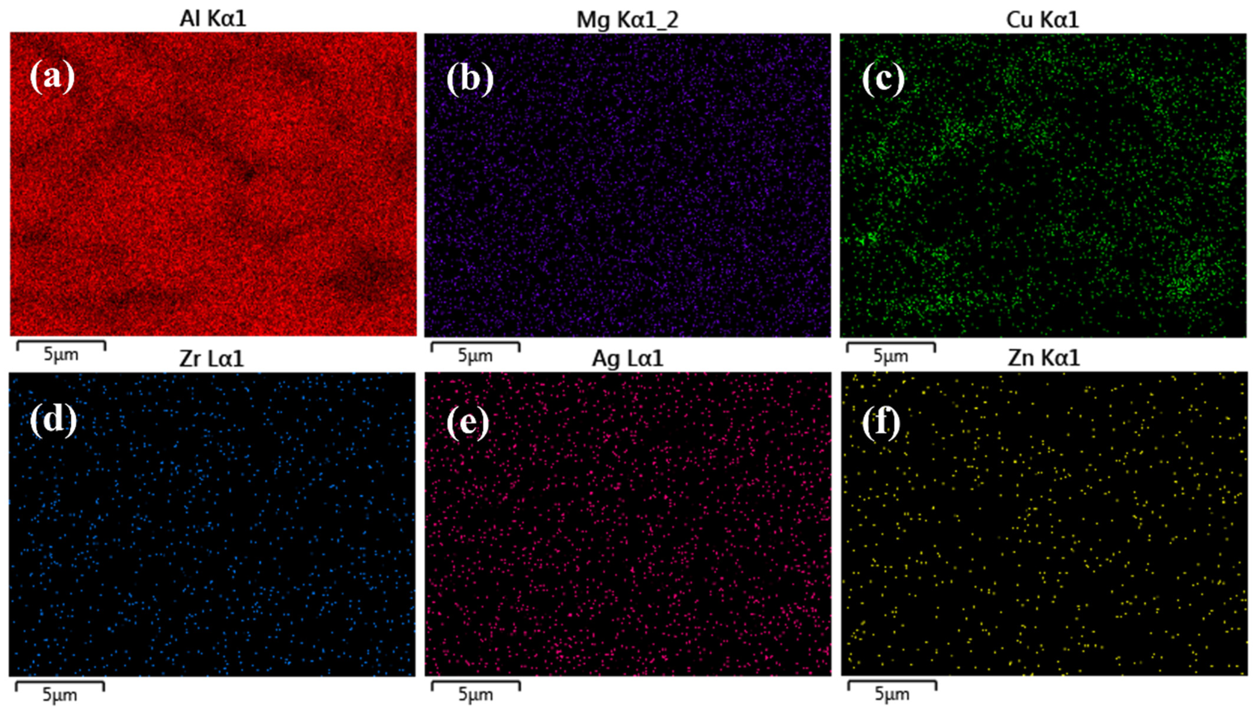
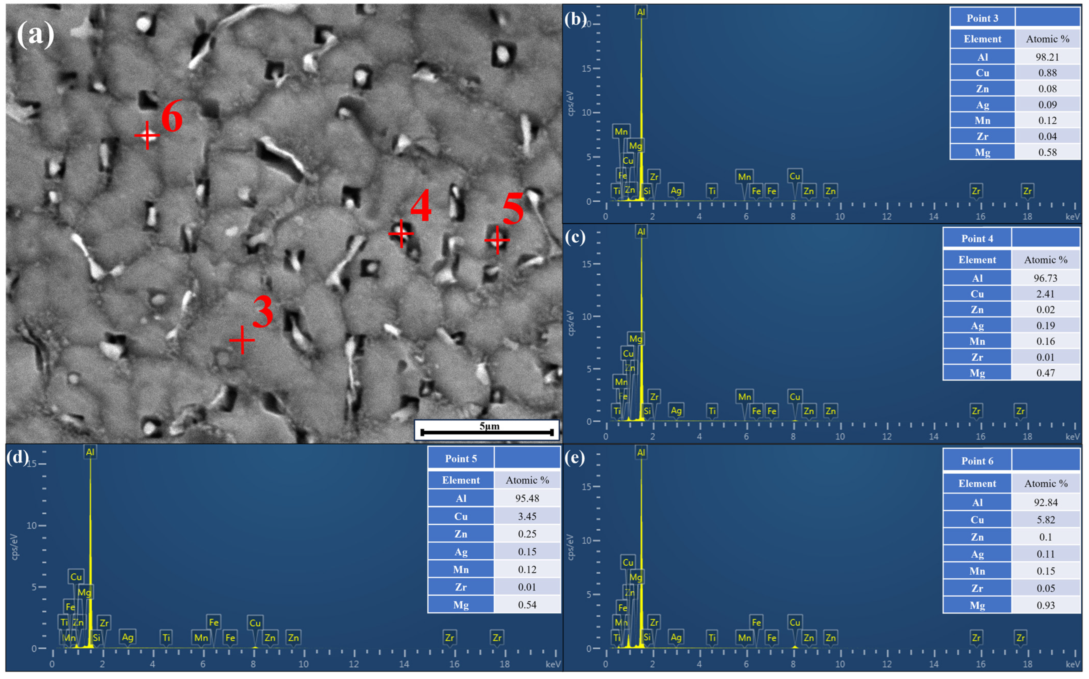
3.3.2. Phase Analysis
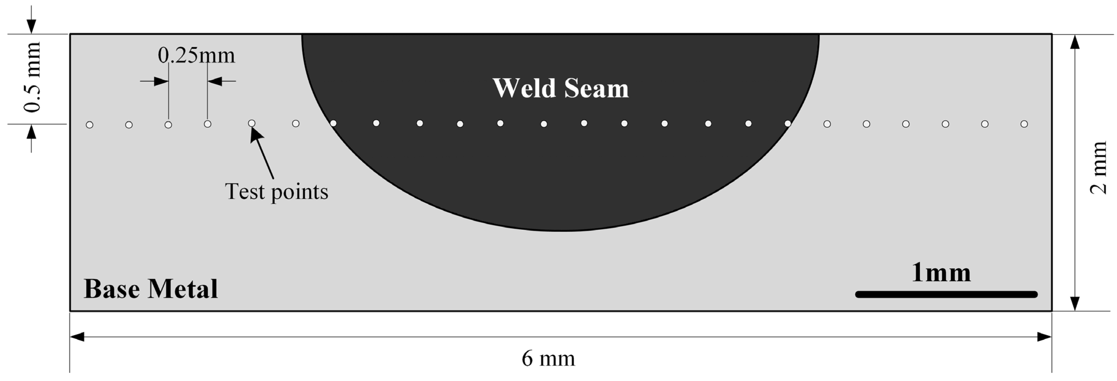
3.4. Microhardness
4. Mechanism Analysis
5. Conclusions
- (1)
- Laser beam oscillation welding was more effective than pure laser welding in preventing the release of plasma gas and metal vapor from the weld pool, thus reducing spattering. Consequently, the LBOW process was more stable.
- (2)
- The O-shaped scanning path was more resistant to the impact of laser power and yielded the optimal weld shape in comparison to pure laser and ∞-shaped scanning paths.
- (3)
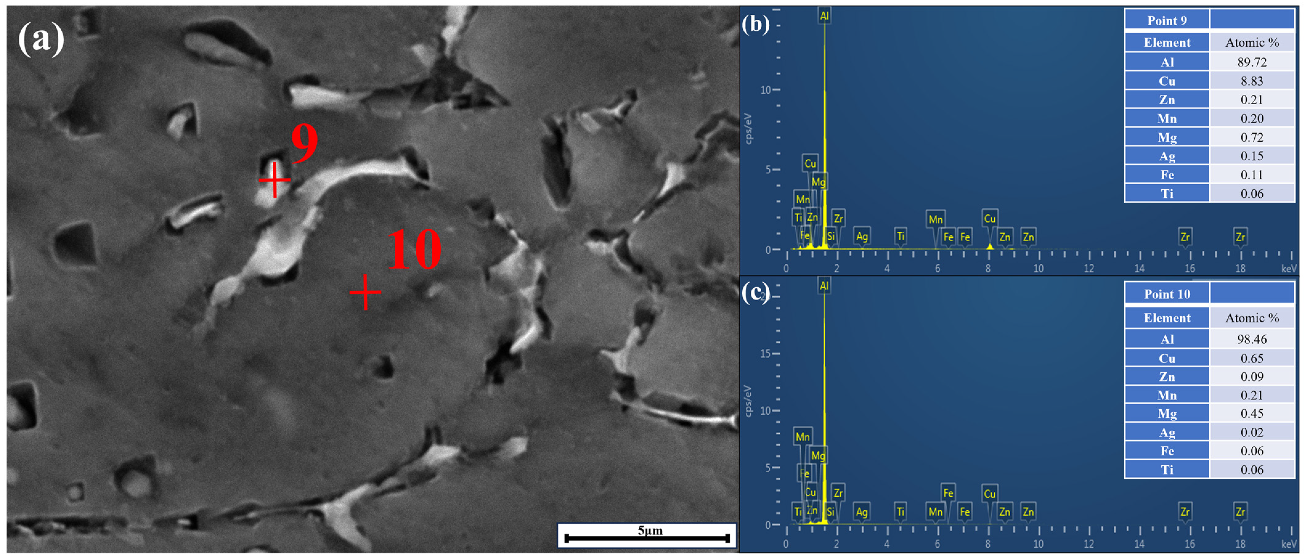
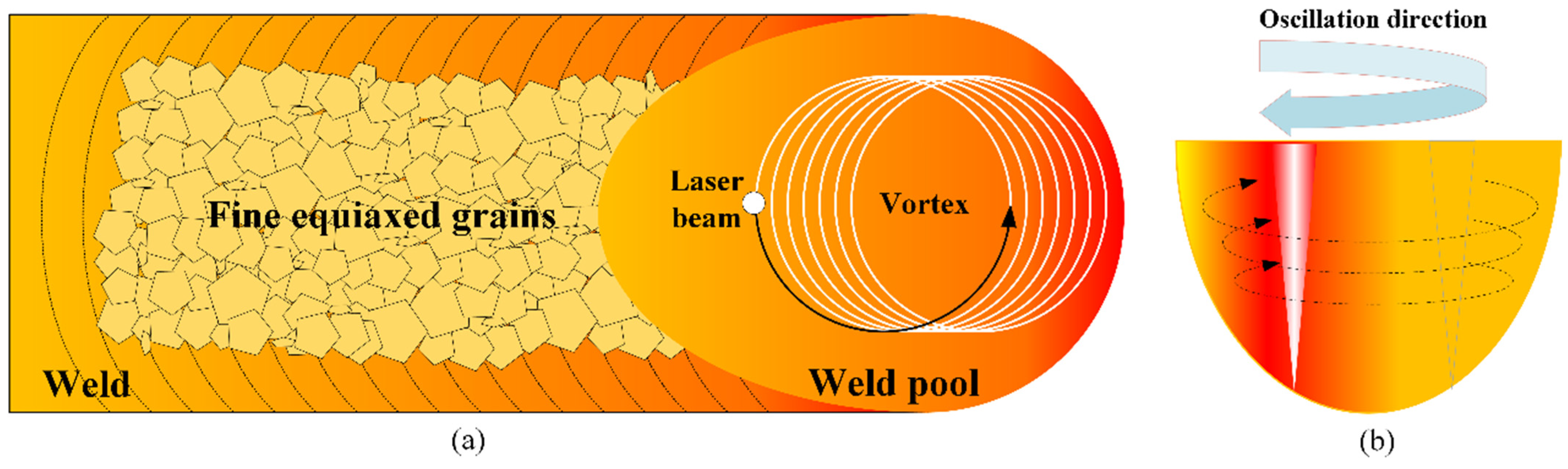
- The Zr element promoted the microstructure formation of EQZ, the equiaxed dendrites and columnar dendrites were mainly composed of α-Al solid solution and Al2Cu eutectic phase, and PMZ was similar in composition to the base metal.
- (4)
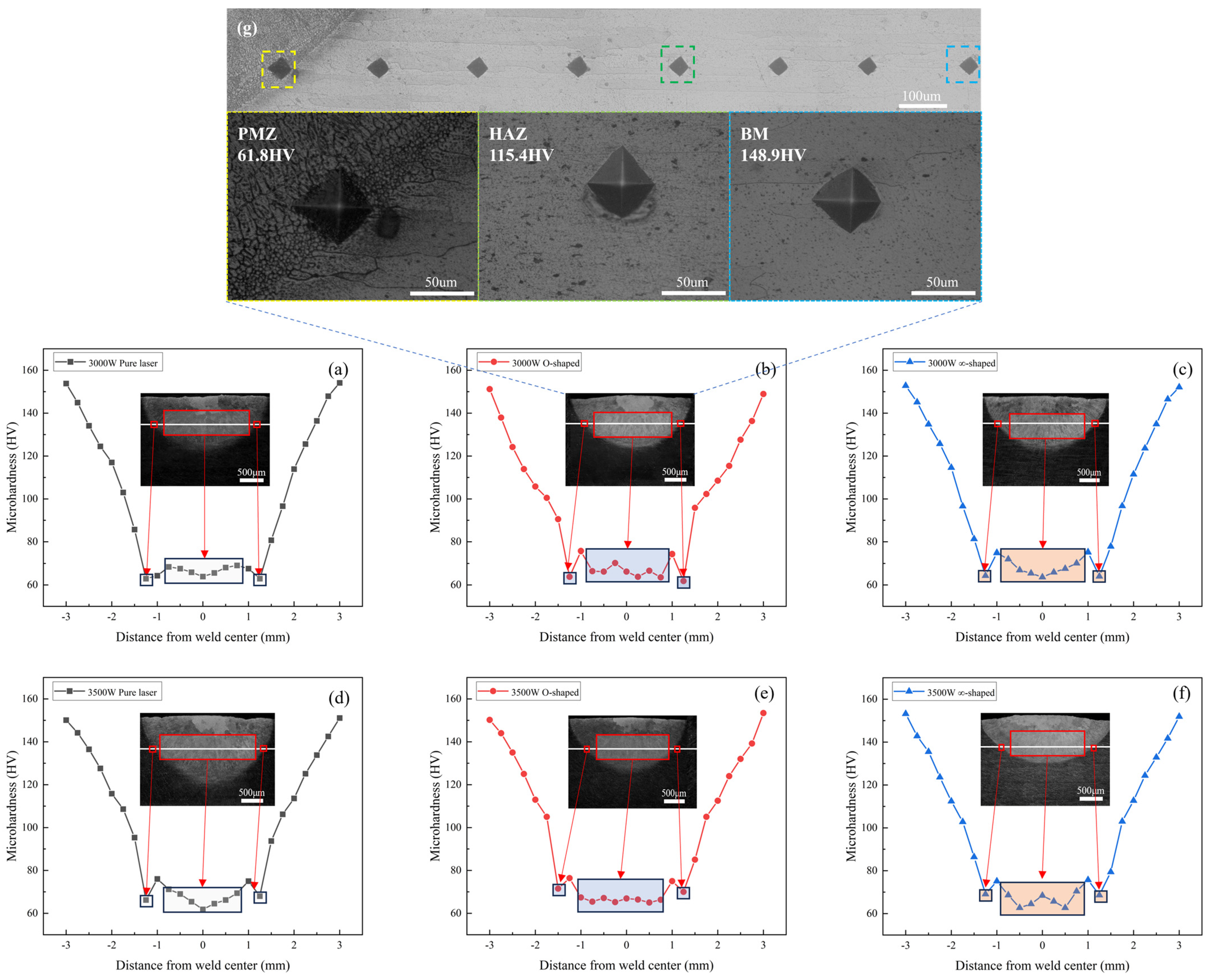
- LBOW could reduce the width of the EQZ and decrease the pores to improve the mechanical properties of the weld, in which the microhardness of the weld center could be increased by 5.6% under a laser power of 3000 W for O-shaped scanning path laser welding compared to pure laser welding, which means that LBOW provides a small improvement in mechanical properties.
Author Contributions
Funding
Institutional Review Board Statement
Data Availability Statement
Conflicts of Interest
References
- Li, S.S.; Yue, X.; Li, Q.Y.; Peng, H.L.; Dong, B.X.; Liu, T.S.; Yang, H.Y.; Fan, J.; Shu, S.L.; Qiu, F.; et al. Development and applications of aluminum alloys for aerospace industry. J. Mater. Res. Technol. 2023, 27, 944–983. [Google Scholar] [CrossRef]
- Ma, P.P.; Zhan, L.H.; Liu, C.H.; Wang, Q.; Li, H.; Liu, D.B.; Hu, Z.G. Pre-strain-dependent natural ageing and its effect on subsequent artificial ageing of an Al-Cu-Li alloy. J. Alloys Compd. 2019, 790, 8–19. [Google Scholar] [CrossRef]
- Zhao, Y.Q.; Wu, Y.F.; Chen, M.L.; Gu, Y.Z.; Zhan, X.H. Research on the stripping performance during dual laser-beam bilateral synchronous welding of 2219 aluminum alloy T-joint for spacecraft. J. Manuf. Process. 2019, 45, 33–45. [Google Scholar] [CrossRef]
- Zhang, J.; Wang, C.; Zhang, Y.; Deng, Y.L. Effects of creep aging upon Al-Cu-Li alloy: Strength, toughness and microstructure. J. Alloys Compd. 2018, 764, 452–459. [Google Scholar] [CrossRef]
- Dorin, T.; De Geuser, F.; Lefebvre, W.; Sigli, C.; Deschamps, A. Strengthening mechanisms of T1 precipitates and their influence on the plasticity of an Al-Cu-Li alloy. Mat. Sci. Eng. A Struct. 2014, 605, 119–126. [Google Scholar] [CrossRef]
- Jiang, N.; Jiang, M.; Chen, X.; Han, T.; Ma, S.; Chen, Y.; Wang, Z.; Jiang, Y.; Yang, L.; Lei, Z.; et al. Effect of beam oscillation on weld formation, microstructure and mechanical properties in vacuum laser beam welding of thick section 5083 aluminum alloy. Opt. Laser Technol. 2024, 171, 110408. [Google Scholar] [CrossRef]
- Zheng, M.; Yang, J.; Xu, J.Y.; Jiang, J.W.; Zhang, H.; Oliveira, J.P.; Lv, X.Q.; Xue, J.; Li, Z.G. Interfacial microstructure and strengthening mechanism of dissimilar laser al/steel joint via a porous high entropy alloy coating. J. Mater. Res. Technol. 2023, 23, 3997–4011. [Google Scholar] [CrossRef]
- Bi, J.; Wu, L.; Liu, Z.; Wang, H.; Li, Q.; Yang, Z. Coupling effect of ultrasonic vibration and beam oscillation on FQZ soften inhibition of laser welded Al-Mg alloy joints. Mater. Lett. X 2023, 18, 100197. [Google Scholar] [CrossRef]
- Jiang, J.W.; Oliveira, J.P.; Yang, J.; Zheng, M.; Li, H.Y.; Xu, W.H.; Wu, L.Q.; Dou, T.Y.; Wang, R.J.; Tan, C.W. Effect of defocusing distance on interfacial reaction and mechanical properties of dissimilar laser Al/steel joints with a porous high entropy alloy coating. Mater. Charact. 2024, 210, 113751. [Google Scholar] [CrossRef]
- Wang, X.; Luo, Y.P.; Huang, T.; Liu, H.X. Experimental Investigation on Laser Impact Welding of Fe-Based Amorphous Alloys to Crystalline Copper. Materials 2017, 10, 523. [Google Scholar] [CrossRef]
- Gong, J.; Li, L.; Meng, S.; Huang, R.; Zou, J.; Cao, H. Study on stability and microstructure properties of oscillating laser welded 5A06 alloy with narrow gap. Opt. Laser Technol. 2022, 155, 108360. [Google Scholar] [CrossRef]
- Liu, F.Y.; Tan, C.W.; Wu, L.J.; Gong, X.T.; Chen, B.; Song, X.G.; Zhao, H.Y.; Wang, G.D. Influence of waveforms on Laser-MIG hybrid welding characteristics of 5052 aluminum alloy assisted by magnetic field. Opt. Laser Technol. 2020, 132, 106508. [Google Scholar] [CrossRef]
- Chen, C.; Wang, W.Y.; Li, D.Y.; Cai, Y.M.; Zhang, Y.H.; Zhang, K. Effect of beam oscillation on microstructure and properties of laser-TIG hybrid welding of D406A ultra-high strength steel. J. Manuf. Process. 2020, 57, 798–805. [Google Scholar] [CrossRef]
- Thiel, C.; Hess, A.; Weber, R.; Graf, T. Stabilization of laser welding processes by means of beam oscillation. Laser Sources Appl. 2012, 8433, 225–234. [Google Scholar]
- Ai, Y.; Yu, L.; Huang, Y.; Liu, X. The investigation of molten pool dynamic behaviors during the “∞” shaped oscillating laser welding of aluminum alloy. Int. J. Therm. Sci. 2022, 173, 107350. [Google Scholar] [CrossRef]
- Chen, G.Y.; Wang, B.; Mao, S.; Zhong, P.X.; He, J. Research on the “∞”-shaped laser scanning welding process for aluminum alloy. Opt. Laser Technol. 2019, 115, 32–41. [Google Scholar] [CrossRef]
- Wang, Z.M.; Oliveira, J.P.; Zeng, Z.; Bu, X.Z.; Peng, B.; Shao, X.Y. Laser beam oscillating welding of 5A06 aluminum alloys: Microstructure, porosity and mechanical properties. Opt. Laser Technol. 2019, 111, 58–65. [Google Scholar] [CrossRef]
- Chmelko, V.; Berta, I.; Margetin, M. Influence of Heat Treatment Process to the Fatigue Properties of High Strength Steel. In Proceedings of the 19th International Colloquium on Mechanical Fatigue of Metals (ICMFM), Porto, Portugal, 5–7 September 2018; pp. 35–40. [Google Scholar]
- Wang, Y.; Wu, G.; Zhang, L.; Guo, Y.; Wang, C.; Li, L.; Xiong, X. Microstructure evolution and mechanical properties of a cast and heat-treated Al–Li–Cu–Mg alloy: Effect of cooling rate during casting. Mater. Sci. Eng. A 2023, 880, 145366. [Google Scholar] [CrossRef]
- Zhang, X.D.; Chen, W.Z.; Bao, G.; Zhao, L. Improvement of weld quality using a weaving beam in laser welding. J. Mater. Sci. Technol. 2004, 20, 633–636. [Google Scholar]
- Zhang, C.; Li, X.W.; Gao, M. Effects of circular oscillating beam on heat transfer and melt flow of laser melting pool. J. Mater. Res. Technol. 2020, 9, 9271–9282. [Google Scholar] [CrossRef]
- Smith, S.; Blackburn, J.; Gittos, M.; Bono, P.D.; Hilton, P. Welding of dissimilar metallic materials using a scanned laser beam. In Proceedings of the ICALEO® 2013: 32nd International Congress on Laser Materials Processing, Laser Microprocessing and Nanomanufacturing, Miami, FL, USA, 6–10 October 2013. [Google Scholar]
- Xia, L.; Zhan, X.H.; Yu, H.S.; Xia, P.Y.; Feng, X.S.; Wang, Z.D. Morphology and formation mechanism of equiaxed grains along the fusion boundary in Al-Li alloy weld seam. Mater. Res. Express 2018, 5, 116523. [Google Scholar] [CrossRef]
- Cui, G.; Yang, C. Formation and strengthening mechanism of equiaxial cellular grain zone in AA2195-T8 Al–Cu–Li alloy twin-wire P-VPPA welded joint with Ti–Zr microalloying. Mat. Sci. Eng. A 2024, 896, 146278. [Google Scholar] [CrossRef]
- Peng, S.S.; Zou, J.L.; Li, X.T.; Wu, Q.; Xiao, R.S. Fiber Laser High-Frequency Focus Rotation Spot Welding Process Based on Thermal Conductivity. Chin. J. Lasers-Zhongguo Jiguang 2018, 45, 1102011. [Google Scholar] [CrossRef]
- Han, B.; Chen, Y.B.; Tao, W.; Lei, Z.L.; Li, H.; Guo, S.; Li, P. Nano-indentation investigation on the local softening of equiaxed zone in 2060-T8/2099-T83 aluminum-lithium alloys T-joints welded by double-sided laser beam welding. J. Alloys Compd. 2018, 756, 145–162. [Google Scholar] [CrossRef]
- Lei, X.; Nuam, V.L.; Yuan, Y.; Bai, Y.; Yao, W.; Wang, N. Investigation on laser beam remelted Al-Cu-Li alloy part II: Corrosion behavior and mechanical properties. J. Alloys Compd. 2021, 873, 159765. [Google Scholar] [CrossRef]
- Liu, H.B.; Sun, Y.Y.; Xie, R.S.; Chen, Y.; Chen, S.J. Characterization of microstructure and local mechanical properties of friction rolling additive manufactured Al-Li alloy under repeated thermal-mechanical cycles. Mater. Charact. 2023, 204, 113169. [Google Scholar] [CrossRef]
- Jiang, T.; Zhang, M.; Dai, G.; Shen, Z.; Guo, Y.; Sun, Z.; Li, W. Microstructure evolution and mechanical properties of ultrafine-grained Al-Li alloy fabricated via friction stir additive manufacturing. Mater. Charact. 2024, 209, 113760. [Google Scholar] [CrossRef]
- Wang, X.; Liu, W.; Xu, G.; Zhu, J.; Hu, Q.; Du, B. Numerical analysis of dynamic coupling between the keyhole and molten pool in the rotating laser welding process of aluminum alloy. Int. J. Adv. Manuf. Technol. 2022, 121, 5491–5502. [Google Scholar] [CrossRef]
- Hosseini, S.A.; Abdollah-zadeh, A.; Naffakh-Moosavy, H.; Mehri, A. Elimination of hot cracking in the electron beam welding of AA2024-T351 by controlling the welding speed and heat input. J. Manuf. Process. 2019, 46, 147–158. [Google Scholar] [CrossRef]
- Wang, F.; Liu, Z.; Qiu, D.; Taylor, J.A.; Easton, M.A.; Zhang, M.-X. Revisiting the role of peritectics in grain refinement of Al alloys. Acta Mater. 2013, 61, 360–370. [Google Scholar] [CrossRef]


| Element | Cu | Li | Zn | Mg | Mn | Zr | Ag | Si | Fe | Ti | Al |
|---|---|---|---|---|---|---|---|---|---|---|---|
| Percent | 3.9 | 0.8 | 0.32 | 0.7 | 0.29 | 0.1 | 0.34 | 0.02 | 0.02 | <0.1 | Bal. |
| Sample | Scanning Path | Laser Power P (W) | Welding Speed V (mm/s) | Scanning Frequency F (Hz) | Scanning Amplitude A (mm) |
|---|---|---|---|---|---|
| 1 | Pure laser | 3000 | 35 | 0 | 0 |
| 2 | O-shaped | 3000 | 35 | 100 | 1 |
| 3 | ∞-shaped | 3000 | 35 | 100 | 1 |
| 4 | Pure laser | 3500 | 35 | 0 | 0 |
| 5 | O-shaped | 3500 | 35 | 100 | 1 |
| 6 | ∞-shaped | 3500 | 35 | 100 | 1 |
| Process Parameters | Top-Surface | Cross-Section |
|---|---|---|
| Pure laser |  |  |
| O-shaped | 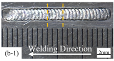 | 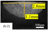 |
| ∞-shaped | 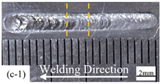 |  |
| Process Parameters | Top-Surface | Cross-Section |
|---|---|---|
| Pure laser | 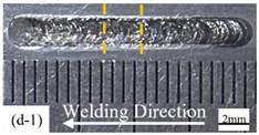 | 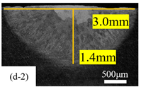 |
| O-shaped | 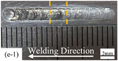 | 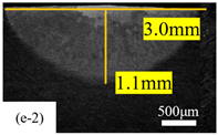 |
| ∞-shaped | 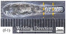 |  |
Disclaimer/Publisher’s Note: The statements, opinions and data contained in all publications are solely those of the individual author(s) and contributor(s) and not of MDPI and/or the editor(s). MDPI and/or the editor(s) disclaim responsibility for any injury to people or property resulting from any ideas, methods, instructions or products referred to in the content. |
© 2024 by the authors. Licensee MDPI, Basel, Switzerland. This article is an open access article distributed under the terms and conditions of the Creative Commons Attribution (CC BY) license (https://creativecommons.org/licenses/by/4.0/).
Share and Cite
Song, Y.; Liang, Y.; Liu, H.; Lin, L.; Gao, Y.; Zhang, H.; Yang, J. Influence of Scanning Paths on the Weld Pool Behavior, Microstructure, and Mechanical Property of AA2060 Al-Li Alloy Joints by Laser Beam Oscillation Welding. Coatings 2024, 14, 1065. https://doi.org/10.3390/coatings14081065
Song Y, Liang Y, Liu H, Lin L, Gao Y, Zhang H, Yang J. Influence of Scanning Paths on the Weld Pool Behavior, Microstructure, and Mechanical Property of AA2060 Al-Li Alloy Joints by Laser Beam Oscillation Welding. Coatings. 2024; 14(8):1065. https://doi.org/10.3390/coatings14081065
Chicago/Turabian StyleSong, Yanbo, Ying Liang, Hongbing Liu, Luchan Lin, Yanfeng Gao, Hua Zhang, and Jin Yang. 2024. "Influence of Scanning Paths on the Weld Pool Behavior, Microstructure, and Mechanical Property of AA2060 Al-Li Alloy Joints by Laser Beam Oscillation Welding" Coatings 14, no. 8: 1065. https://doi.org/10.3390/coatings14081065