Article

Effect of Bushing Structure on Mechanical Properties and Failure Mechanism of CFRP Laminated Titanium Nail Riveting

1
School of Mechanical Engineering, Anhui University of Technology, Maanshan 243032, China
2
College of Mechanical and Electrical Engineering, Suqian University, Suqian 223800, China
*
Author to whom correspondence should be addressed.
Coatings 2024, 14(8), 1076; https://doi.org/10.3390/coatings14081076
Submission received: 1 August 2024 / Revised: 19 August 2024 / Accepted: 21 August 2024 / Published: 22 August 2024
(This article belongs to the Special Issue Recent Developments in Interfaces and Surfaces Engineering)

Abstract

:
In the aerospace field, the riveting process is one of the main methods for connecting the Carbon Fiber Reinforced Polymer/Plastic (CFRP). During the riveting process, components are prone to problems such as damage to CFRP hole walls and reduction in joint strength. To this end, this paper proposes two new bushing structures based on riveting. The riveting damage behavior and mechanical properties of composite materials under three riveting methods: non-bushing, non-boss bushing, and boss bushing were compared. Furthermore, the tensile and hysteretic mechanical properties of CFRP under different riveting structures were studied. The results show that the stress distribution around the hole is more uniform than that of the non-bushing riveting method, and the delamination damage at the hole wall is significantly reduced. In the tensile test, the maximum tensile loads of the non-boss bushing and the boss bushing increased by 2.49% and 5.03% compared to the non-boss bushing schemes. In addition, the tensile failure modes of the three schemes also showed different failure modes due to different riveting forms. The failure mode of the non-bushing riveting scheme is rivet shear failure, and the failure mode of the bushing riveting scheme is rivet pull-off failure. In the hysteretic test, the maximum tensile loads of the non-boss bushing and the boss bushing increased by 5.49% and 12.03% compared to the non-bushing scheme. The failure mode of the three schemes is rivet pull-off failure. The bushing structure not only enhances the connection strength, but also improves the damage to the CFRP hole wall. This study provides a new understanding of the design and optimization of CFRP riveted connection structures.

1. Introduction

CFRP is widely used in aerospace, weapons and equipment, and automotive fields because of its many advantages such as high specific strength and good fatigue properties [1,2,3,4]. In aerospace, CFRP plays a vital role in structural design, predominantly employing adhesive, bolted, riveted, and hybrid connections [5,6,7,8]. Adhesive bonding can uniformly distribute stress across the joint surface and alleviate stress concentrations. But its quality is sensitive to environmental temperature and humidity [9,10]. Bolted connections can provide greater connection strength, but are relatively expensive and of high mass [11,12]. In contrast, riveting is a commonly used form of connection with the advantages of lower cost, lower quality, and simple process [13,14]. However, the riveting process of CFRP often results in damage to the rivet holes. In a cyclic loading environment, initial notches and high-stress concentrations in the joint region can significantly diminish load-bearing capacity and reliability [15,16,17].
In addition, the mechanical properties of CFRP are different from those of metal materials, and the forms of damage and defects at the connection structure are more complex and diverse. Due to the extrusion force and impact force caused by the expansion of the rivet during the riveting process, structural delamination, fiber rupture, and other damages may be caused [18,19,20,21]. Liu et al. [22] investigated the damage evolution and mechanical behavior of self-piercing riveted connections between CFRP and AA5754 aluminum alloy. They proposed a constitutive model for CFRP damage influenced by shear effects and identified the damage patterns of various laminated structural joints through experiments and simulations. Tarpani et al. [23] examined fatigue damage mechanisms in single-shear lap joints of double-riveted fiber-metal laminated structures. They found that the fatigue strength of the laminated structure, with two rivets aligned along the loading direction, is approximately 1.5 to 2.0 times greater than that of non-aligned rivet connections. Borba et al. [24] investigated the sensitivity of carbon fiber reinforced polyether ether ketone (PEEK) friction riveted joints to impact damage and damage propagation during fatigue and quasi-static mechanical testing. They found that impact energies ranging from 5 J to 30 J caused the joints to exhibit both invisible and visible damage, with the visible damage leading to a 40% reduction in the joints’ quasi-static strength.
At present, scholars have proposed two ways to improve the quality of riveting: The first is to adopt advanced riveting technology to improve rivet forming and reduce extrusion damage caused by rivet expansion to the hole wall, such as electromagnetic riveting, current-assisted riveting technology, and transverse ultrasonic vibration-assisted riveting technology [25,26]. The second is to protect the composite hole structure, such as using washers, bushings, and embedded parts [27,28]. Zhang et al. [29] investigated the influence of the double-sided countersunk electromagnetic riveting process on the damage behavior and interference characteristics of CFRP connections through experiments and finite element simulations. Qi et al. [30] used current-assisted methods to improve the ductility of titanium alloy rivets. In addition, the study found that when the current is controlled within 16.5 A/mm2, the pressure required for riveting can be significantly reduced and the uniformity of rivet deformation can be improved. Shao et al. [31] proposed a new low-frequency vibration-assisted self-piercing riveting (LVSPR) technology to improve the connection strength between CFRP and high-strength metal plates. This method can reduce riveting force and CFRP damage, and enhance joint performance. Yang et al. [32] proposed a riveting method with gaskets to solve the damage problem caused by riveting in CFRP structures. Through tension-shear tests and pull-out tests, it is verified that this method can reduce damage and enhance the connection strength of CFRP specimens. Qu et al. [33] designed a new type of composite rivet with a sleeve. The use of sleeve structures reduces the riveting compressive stress and improves the double-sided countersunk riveting quality of CFRP wedge structures, thereby reducing material damage. However, the focus of the above research mainly focuses on static strength tests such as tensile and drawing, while relatively few studies on cyclic loading properties have been conducted.
The purpose of this study was to determine the effect of bushings on the bearing capacity and failure modes of CFRP structures under monotonic and cyclic loads in different bushing structural protections.

2. Materials and Methods

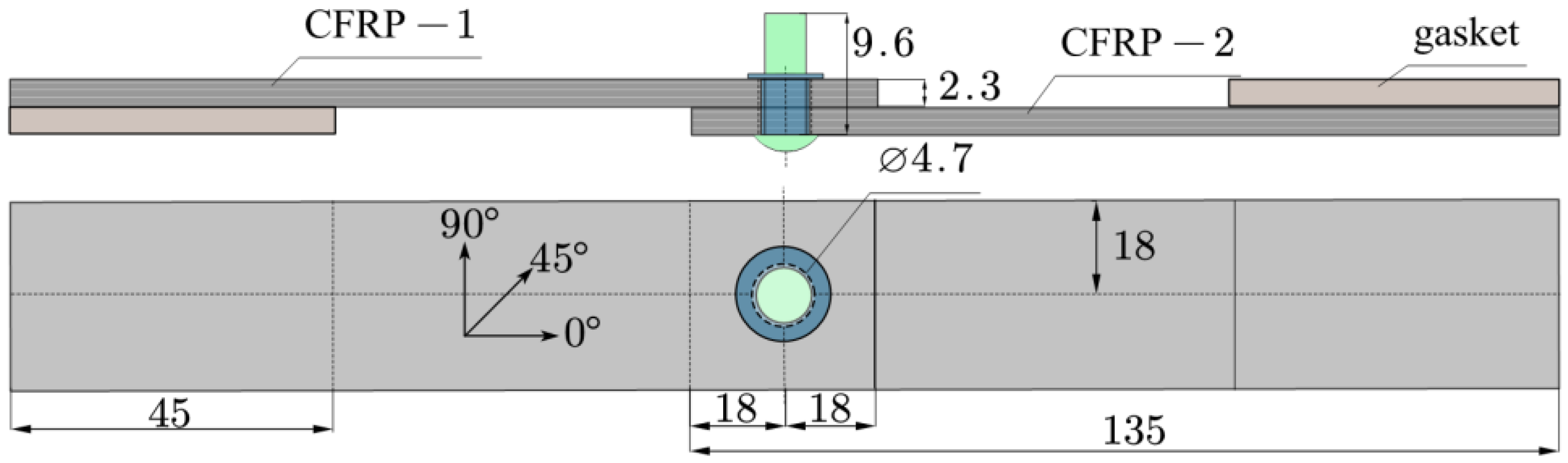
2.1. Specimen Preparation

As shown in Figure 1, the structure consists of a T700 plate, Ti-45Nb rivets, and bushings. The laying order is braid +[0/45/ − 45/90/0]s+ braid. There are twelve layers with a total thickness of 2.3 mm, and the test piece size is 135 mm × 36 mm. The rivet diameter is Ø 3.98 mm, and the rivet shank length is 9.6 mm. Two structures of bushings were designed: non-boss bushings and boss bushings. The bushing rod length is 4.6 mm, the outer diameter is Ø 4.6 mm, the inner diameter is Ø 4 mm, the wall thickness is 0.3 mm, and the boss diameter is Ø 6 mm.

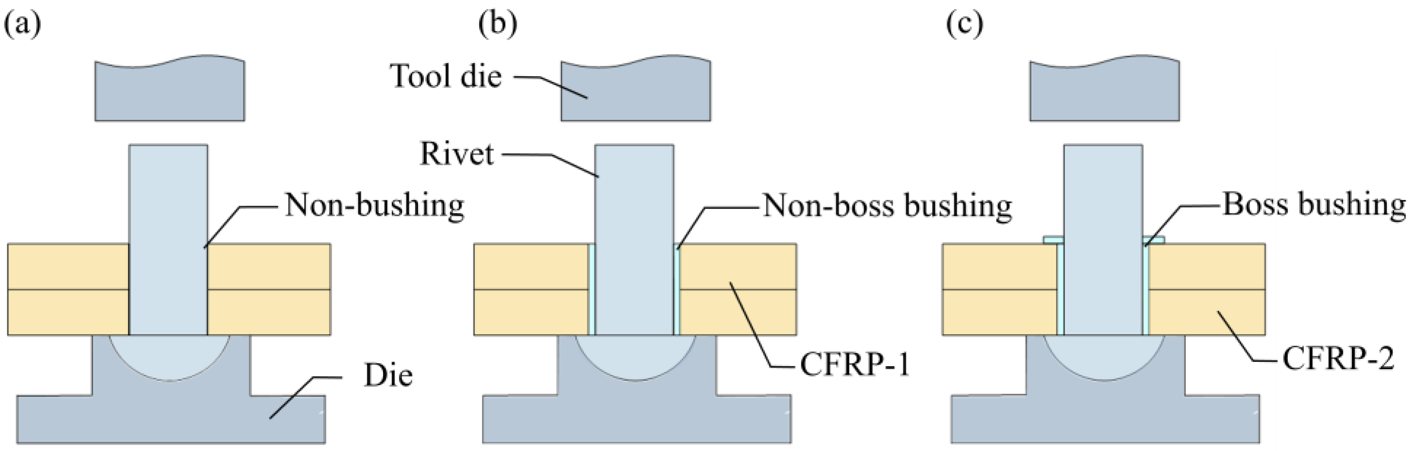
2.2. Riveting Test Scheme

In this study, three riveting schemes are compared. The first scheme is non-bushing riveting, with a diameter of Ø 4.1 mm. Place the rivet into the rivet hole and compress the rivet. The second scheme is riveted non-boss bushing, and the diameter of the CFRP riveting hole is Ø 4.7 mm. Place the non-boss bushing and rivet into the rivet hole, and then compress the rivet. The third scheme is boss bushing riveting, and the diameter of the CFRP riveting hole is Ø 4.7 mm. Place the boss bushing and rivet into the rivet hole and compress the rivet. For the riveting test, refer to QJ782A-2005 [34] (General Technical Requirements for Riveting). Each group of experiments was repeated three times to calculate the average. Figure 2 illustrates the three riveting methods.

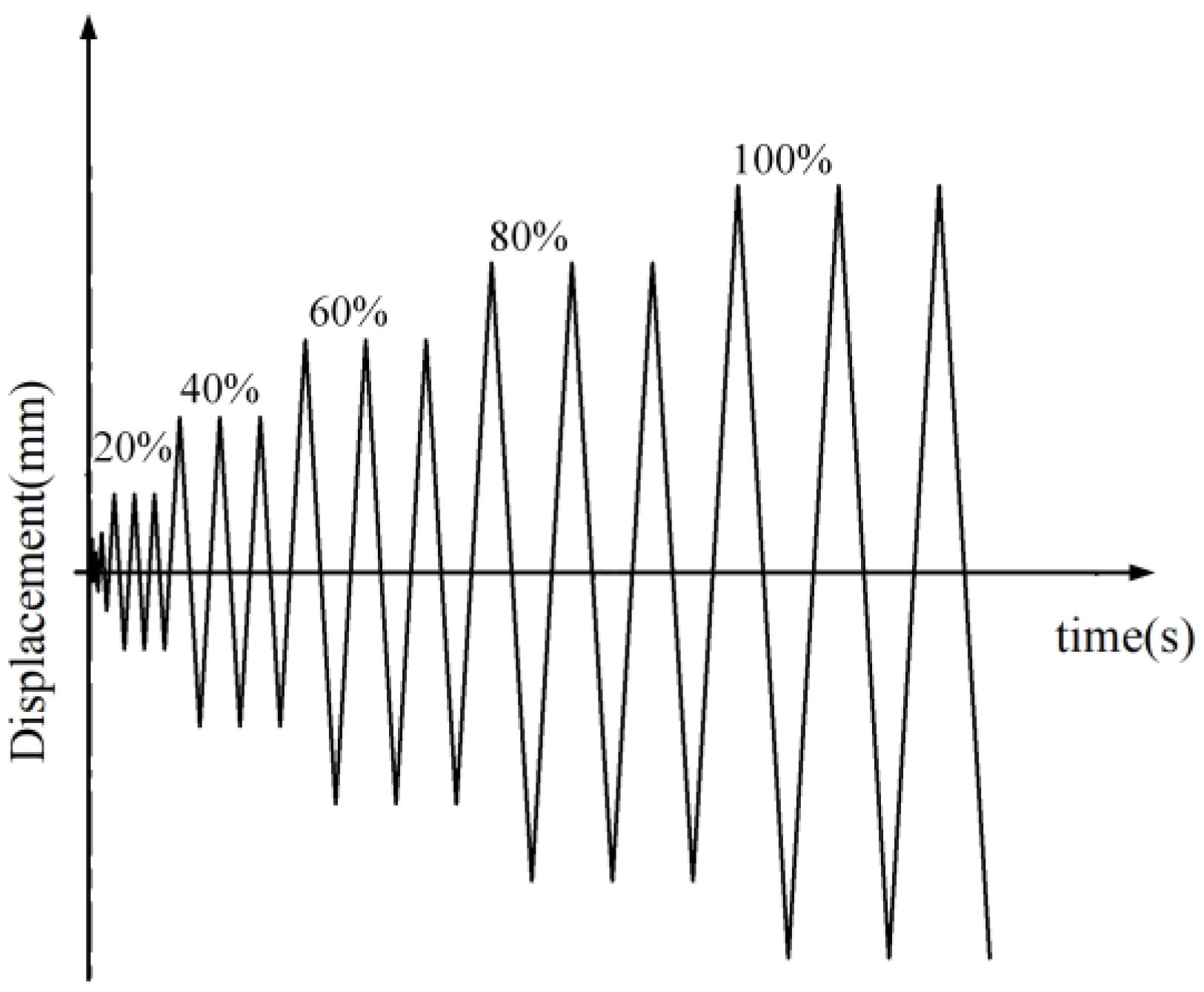
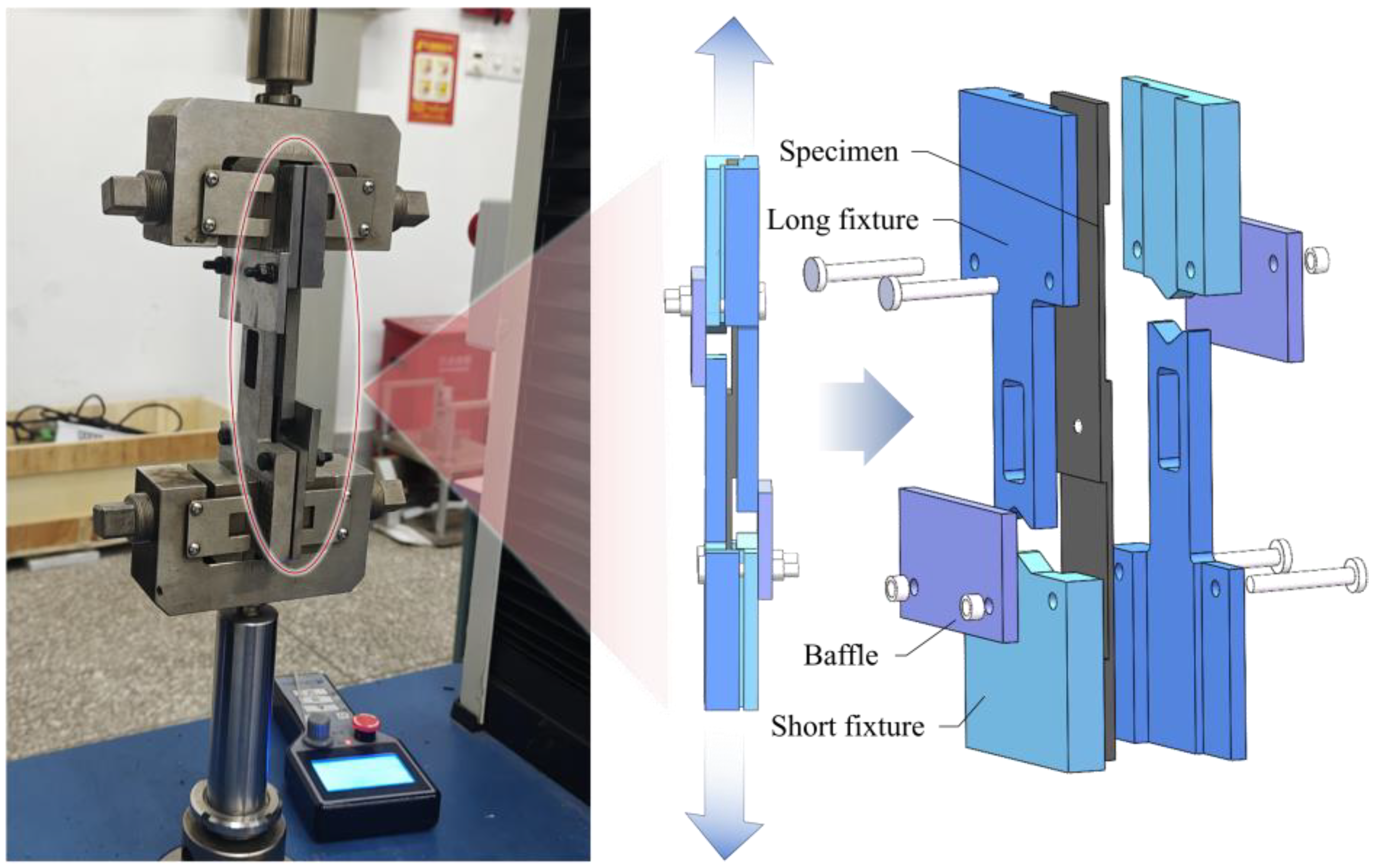
2.3. Mechanical Property Test (Static Tensile Test, Hysteretic Test)

The riveted specimens were used for the tensile test and hysteretic test, respectively. The purpose of this experiment is to explore the seismic performance of CFRP. Currently, no loading standard has been established for hysteretic performance testing of CFRP. Therefore, this paper refers to relevant standards for wood structure testing when formulating the loading procedure. To ensure the consistency of the test materials, the loading system for the tensile test was designed with the ASTM D1761-12 [35] Wood Fastener Test Method. This method adopts a displacement loading method, and the displacement loading rate is 5 mm/min. The hysteretic test loading system refers to the ISO 16670 [36] cyclic loading method for wooden structure pin-type joints. The cyclic loading speed of this method is 6 mm/min. In the tensile test, the displacement corresponding to 80% of the maximum tensile load of the riveting specimen is set as the limit displacement ∆u, and the multiple of this displacement is used as the displacement amplitude, which is 1.25%, 2.5%, 5%, 10%, 20%, 40%, 60%, 80%, and 100%, respectively. When the displacement reaches 20% ∆u, each displacement is cycled 3 times until the sample is pulled off or snapped. The loading system is shown in Figure 3. Each group of experiments was repeated three times to calculate the average. The test was carried out at room temperature (25 °C) using a tensile testing machine, and the equipment and fixtures are shown in Figure 4.

3. Stress Analysis around CFRP Hole

3.1. Establishment of a Riveting Model for CFRP

The three-dimensional finite element model of the bushing riveting process is shown in Figure 5, which includes the CFRP plate, bushing (non-boss, boss), rivet, tool die, and die. The mechanical property parameters of CFRP are shown in Table 1. The mechanical properties of the composite are obtained by calculation of the mixing ratio [37]. The mechanical property parameters of rivets and bushings [38] are shown in Table 2. During modeling, CFRP is modeled in layers, and the material direction is given layer by layer according to the ply order. At the same time, a cohesive layer with a thickness of 0.01 mm was inserted in the middle of each layer to predict delamination damage. The performance parameters between CFRP layers [39] are shown in Table 3.
Hexahedron elements are used to mesh each part of the riveting model. The tool die and die are regarded as rigid bodies and are meshed using a larger grid with a size of 1.8 mm. The rivet forming process belongs to a nonlinear dynamic change process of metal, so a small mesh with a size of 0.18 mm is used. To observe the stress and damage around the hole, the mesh around the CFRP hole was refined by 0.3 mm mesh, and other areas were correspondingly coarsened. The adhesive layer uses the COH3D8 mesh type to predict interlayer damage, and the other component mesh types use C3D8R. The normal behavior adopts “hard contact”. The penalty friction model is adopted for tangential behavior. The contact relationship settings in the model include the contact between the rivet and the upper and lower molds, the contact between the rivet and the bushing, the contact between the rivet and the lower CFRP, the contact between the bushing and the upper and lower CFRP, and the contact between the upper and lower CFRP. The contact relationship in the test was a clearance fit, so the friction coefficient was set to 0.2. The application of loads and boundary conditions is shown in Figure 5. The die and other boundaries are completely fixed and a downward displacement is applied in the center of the tool die to simulate the riveting process of the riveting machine.

3.2. Failure Criteria for CFRP Laminates

3.2.1. CFRP Constitutive Model

CFRP laminates have different properties in different directions, and each layer can be seen as a consistent but differently-acting material. Therefore, CFRP can simplify the stiffness matrix to a symmetric matrix based on the symmetry of the material. The constitutive relationship expression is as follows:
σ 1 σ 2 σ 3 τ 23 τ 31 τ 12 = C 11 C 12 C 13 0 0 0 C 21 C 22 C 23 0 0 0 C 31 C 32 C 33 0 0 0 0 0 0 C 44 0 0 0 0 0 0 C 55 0 0 0 0 0 0 C 66 ε 1 ε 2 ε 3 γ 23 γ 31 γ 12
where C is the stiffness matrix of the composite material, C i j is the stiffness coefficient of the stiffness matrix, σ i is the principal stress tensor, τ i j is the shear stress tensor, E i is the principal strain tensor, and γ i j is the shear strain tensor. At this time, there is no coupling between the principal stress and the shear strain, there is no coupling between the shear stress and the principal strain, and there is no interaction between the shear stress and the shear strain in different planes. Therefore, the stiffness coefficient in the stiffness matrix in Equation (1) is nine independent variables. To better calibrate material properties and give the above formula engineering significance, commonly used engineering constants such as generalized elastic modulus E , Poisson’s ratio v , and shear modulus G are substituted into the matrix to obtain the following:
C 11 = E 1 1 v 23 v 32 Δ C 12 = E 2 v 12 + v 32 v 13 Δ C 13 = E 3 v 13 + v 12 v 23 Δ C 22 = E 2 1 v 13 v 31 Δ C 23 = E 3 v 23 + v 21 v 31 Δ C 33 = E 3 1 v 12 v 21 Δ C 44 = G 12 C 55 = G 23 C 66 = G 13
Δ = 1 v 12 v 21 v 23 v 32 v 13 v 31 2 v 12 v 23 v 31
Subscript 1 represents the fiber direction, 2 represents the fiber direction, and 3 represents the perpendicular to the ply direction. E 1 , E 2 , and E 3 are the elastic moduli in the three principal directions, respectively;  G 12 , G 13 , and G 23 are the shear moduli on planes 12, 13, and 23, respectively;   v 12 , v 13 , and v 23 are the principal Poisson’s ratios on planes 12, 13, and 23, respectively.

3.2.2. Failure Criteria

The basic forms of damage in composite layers include fiber tensile/compression failure and matrix tensile/compression failure. The three-dimensional Hashin failure criterion is the commonly used criterion. However, the fiber tensile failure strength prediction is conservative and slightly smaller than the test value. Therefore, the Chang–Lessard failure criterion was adopted in this paper and shown in Equations (4)–(8)
Fiber tensile failure σ 1 0
F f t = σ 1 X T 2 + τ 12 2 2 G 12 + 3 4 α τ 12 2 S 12 2 2 G 12 + 3 4 α S 12 4 + τ 13 2 2 G 13 + 3 4 α τ 13 2 S 13 2 2 G 13 + 3 4 α S 13 4 1
Fiber compression failure σ 1 < 0
F f c = σ 1 X C 2 1
Matrix tensile failure σ 2 0
F m t = σ 2 Y T 2 + τ 12 2 2 G 12 + 3 4 α τ 12 2 S 12 2 2 G 12 + 3 4 α S 12 4 + τ 23 2 2 G 23 + 3 4 α τ 23 2 S 23 2 2 G 23 + 3 4 α S 23 4 1
Matrix compression failure σ 2 < 0
F m c = σ 2 Y C 2 + τ 12 2 2 G 12 + 3 4 α τ 12 2 S 12 2 2 G 12 + 3 4 α S 12 4 + τ 23 2 2 G 23 + 3 4 α τ 23 2 S 23 2 2 G 23 + 3 4 α S 23 4 1
Fiber-matrix shear failure
F f s = σ 1 X C 2 + τ 12 2 2 G 12 + 3 4 α τ 12 2 S 12 2 2 G 12 + 3 4 α S 12 4 + τ 13 2 2 G 12 + 3 4 α τ 13 2 S 13 2 2 G 13 + 3 4 α S 13 4 1
In the above formulas, X T and X C represent fiber tensile strength and fiber compressive strength, respectively; Y T and Y C represent matrix tensile strength and matrix compressive strength, respectively; S 12 , S 23 , and S 13 represent in-plane shear strengths 12, 23, and 13, respectively; and α is a nonlinear constant.

3.2.3. Damage Evolution Law of CFRP Failure Criteria

When the CFRP reaches its bearing limit, the above-mentioned damage will occur internally. In this paper, a bilinear softening relationship based on stress displacement is used to predict damage evolution [40], as shown in Figure 6. Damage variables d f and d m are defined as the stiffness levels from the initial failure point δ 0 i to the complete failure point δ c i   ( δ c i = c , t ) .
For fiber damage variables d f ,
d f = 1 1 d f i 1 d f c d f i = δ c , 1 i δ c , 1 i δ 0,1 i 1 δ 0,1 i ε 11 i = c , t
In Equation (6), δ 0,1 i corresponds to the critical tension-compression strain at the beginning of damage and δ c , 1 i is calculated from the fracture toughness G , the failure strength X and the characteristic length l .
δ c , 1 i = 2 G 1 i X l ( i = c , t ) l = L initial 3 l z
In Equation (8), c represents compression, t represents extension, L i n i t i a l is the initial element characteristic length obtained by ABAQUS, controlled by the “CharLength” function embedded in VUMAT, and l z is the size of the element body in the global coordinate system.
Similarly, for the matrix damage variable d m ,
d m = 1 1 d m t 1 d m c d m i = δ m , 1 i δ m , 1 i δ 0,1 i 1 δ 0,1 i ε 11 i = c , t

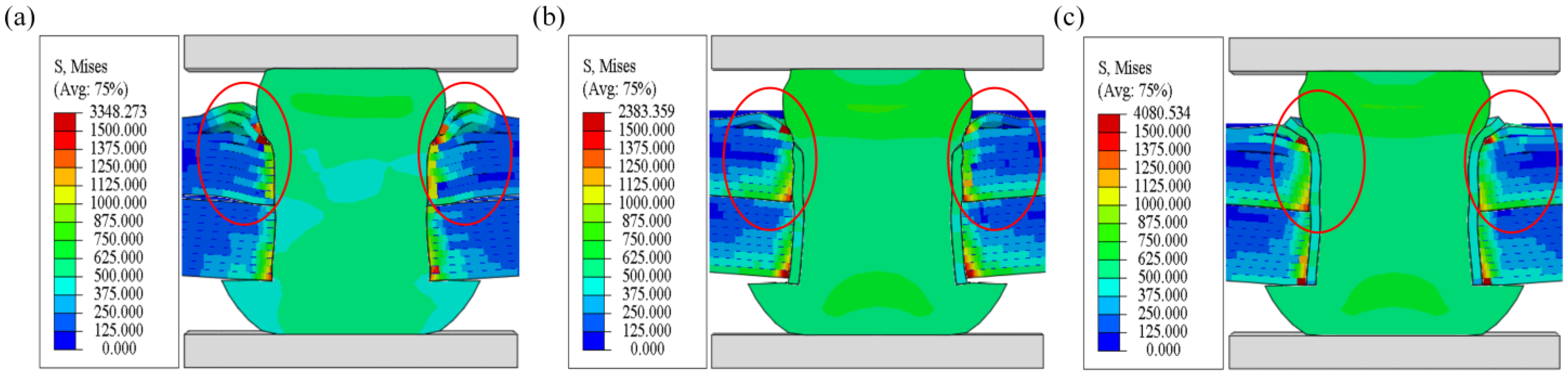
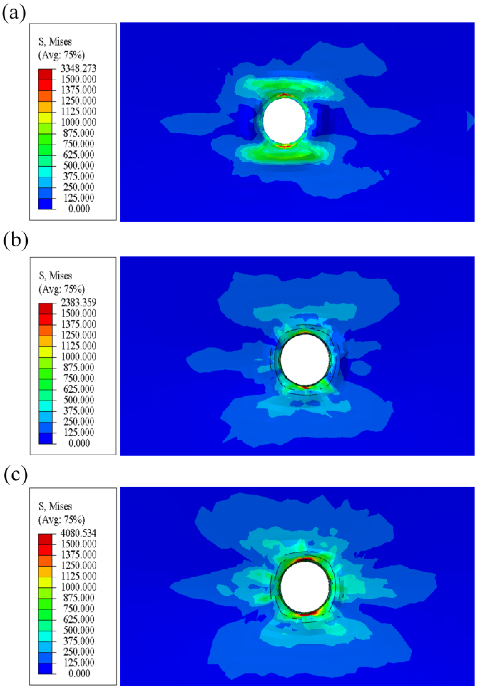
3.3. Riveting Simulation Results

Finite element models of rivets and carbon fiber composite plates were established using ABAQUS software 2023, and the rivet forming process was numerically simulated. The displacement loading method is used in the simulation and the displacement is set to 4 mm.
The simulation results are shown in Figure 7. All three riveting methods cause the CFRP to deform to a certain extent, and the maximum stress of the rivet is located at the contact between the rivet and the upper plate. When the rivet is pressed down in the non-bushing riveting scheme, the pier head expands and compresses the hole wall. There is obvious delamination damage at the top of the hole wall of the upper CFRP plate. In addition, it can be seen from Figure 7a that the stress distribution inside the hole wall and the rivet is uneven, and the average stress on the hole wall is 800 MPa. However, the non-boss bushing protects the hole wall, so the stress distribution inside the rivet is even. It can be seen from Figure 7b that under the protection of the boss bushing, the delamination damage at the top of the hole wall of the CFRP upper plate is reduced. The stress distribution around the hole is uniform, and the average hole wall stress is 600 MPa. It can be seen from Figure 7c that the boss bushing protects the hole wall and the upper surface. The damage to the top of the hole wall of the CFRP upper layer plate is further reduced. The hole wall stress distribution under the protection of boss bushings is similar to that of non-boss bushings, with an average hole wall stress of 600 MPa. Therefore, adding bushings will improve the damage to the CFRP hole wall and upper plate.
During the riveting process, the riveting interference at the entrance of the CFRP structure is the largest. Therefore, the stress distribution around the hole in the 0° ply direction of the CFRP structures is studied. The stress nephograms of the connection holes of the CFRP structures with three riveting schemes are shown in Figure 8a–c. The simulation results show that the stress distribution of the bushing riveting method is uniform and the stress value is reduced compared with the non-bushing riveting method. This also means that the compressive stress on the inlet hole wall due to rivet deformation under the protection of the bushing is reduced.

4. Static Tensile Test Results and Analysis
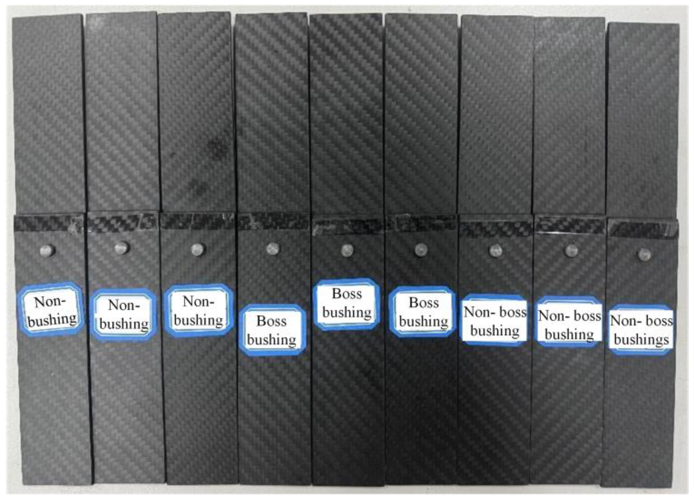
4.1. Riveting Test

Displacement loading control is adopted in the simulation process. However, during the test, in order to better control the pressing amount of riveting, a downforce control method was used. The pressure in the experiment was 20 kN. The riveted specimen is shown in Figure 9.
Figure 10 shows the relationship between the pressing riveting force and tool die displacement. During the pressing riveting process, the displacement curves of the three different riveting methods showed a high degree of consistency within 2 mm. However, when the displacement exceeds 2 mm, the restricting effect of the bushing on the expansion of the rivet gradually appears, resulting in a corresponding acceleration of riveting forming speed, especially for the riveting method of the boss bushing. The riveting displacement of the boss bushing is 3.982 mm, the riveting displacement of the non-boss bushing is 4.106 mm, and the riveting displacement of the non-bushing is 4.145 mm. At the same time, the rivet head diameters of the three schemes are relatively similar.

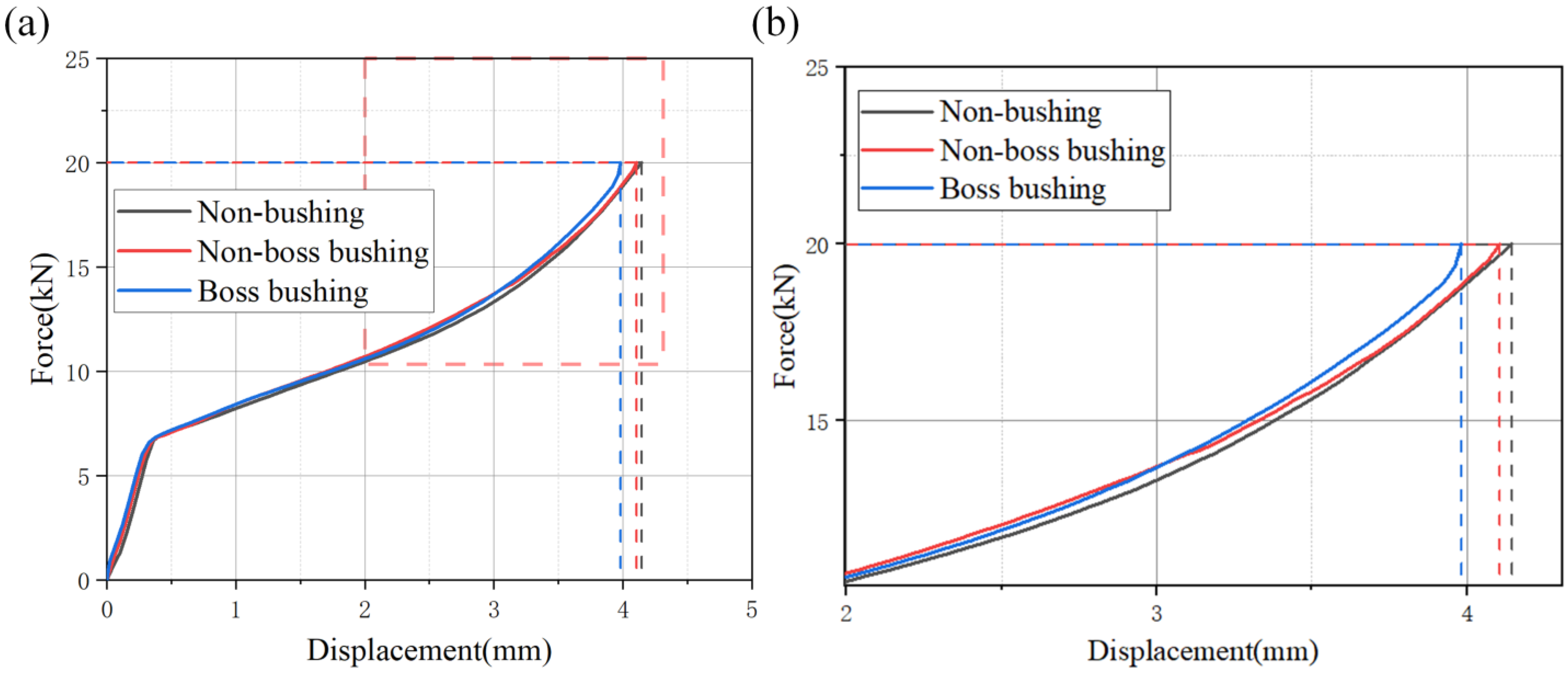
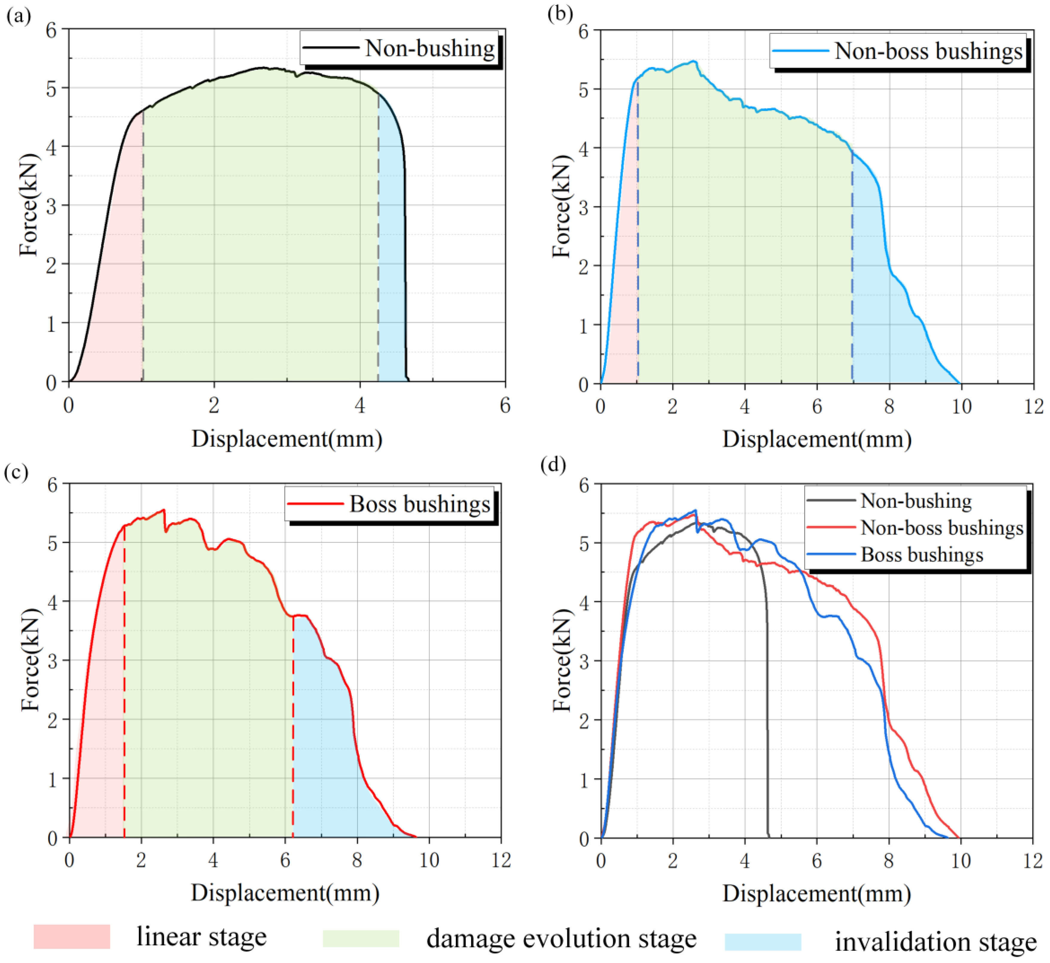
4.2. Load-Displacement Response Analysis

As shown in Figure 11, the yield displacement ∆y is calculated using the equal area method (the blue area and the gray area are equal in area), in the tensile test. The limit displacement ∆u is the displacement at which the connection breaks or the bearing capacity drops to 80% of the peak value.
The load-displacement curves of the three schemes of riveted specimens are shown in Figure 12. There are generally three stages in the tension of CFRP structures, which are the linear stage, damage evolution stage, and failure stage. Linear stage: The curve usually presents a straight line and the material follows Hooke’s Law. Damage evolution stage: The curve begins to show nonlinear characteristics, the slope gradually decreases, and the curve fluctuates. Failure stage: The load-displacement curve shows a sharp drop or a significant inflection point [40]. The red area represents the linear stage, the green area represents the damage evolution stage, and the blue area represents the failure stage. It can be seen from Figure 12a that the damage evolution stage of the non-bushing riveting scheme is relatively smooth. When the specimen reaches the failure stage, the load drops relatively quickly. As can be seen from Figure 12b,c, the load-displacement curves for the non-boss bushing and the boss bushing riveting schemes have similar shapes. This also means that the deformation and damage evolution behaviors of CFRP plates are similar under the two bushing schemes. In the linear stage, the structure deforms elastically but no damage occurs. When the specimen load reaches the critical damage value, the specimen enters the damage evolution stage. At this time, the CFRP is damaged and accumulated, and the load-displacement response shows a wavy shape. In the end, the damage degree of the riveted structure reached the limit value, and the load-bearing capacity was seriously reduced. After entering the failure stage, the load gradually decreases with the increase in displacement.
The length of the damage evolution stage of the non-bushing is 3.2 mm. The length of the damage evolution stage of the non-boss bushing is 5.9 mm, and the damage evolution stage of the boss bushing is 4.7 mm. The results show that the bushing structure can effectively inhibit the damage in the CFRP joint area and significantly enhance the shear properties of the CFRP structures.
The maximum tensile load of the non-bushing riveting is 5.334 kN, and the ultimate displacement is 4.548 mm. The maximum tensile load of the non-boss bushing riveting is 5.467 kN, and the ultimate displacement is 6.014 mm. The maximum tensile load of the boss bushing riveting is 5.549 kN, and the ultimate displacement is 5.618 mm. The tensile test results are shown in Table 4. Because the CFRP hole structure can be protected by the bushings, the tensile and shear properties of the structure are improved to a certain extent. The maximum tensile load of the non-boss bushing riveted piece is 2.49% higher than that of the non-bushing riveted piece, and the tensile load of the boss bushing riveted piece is 4.03% higher than that of the non-bushing riveted piece.

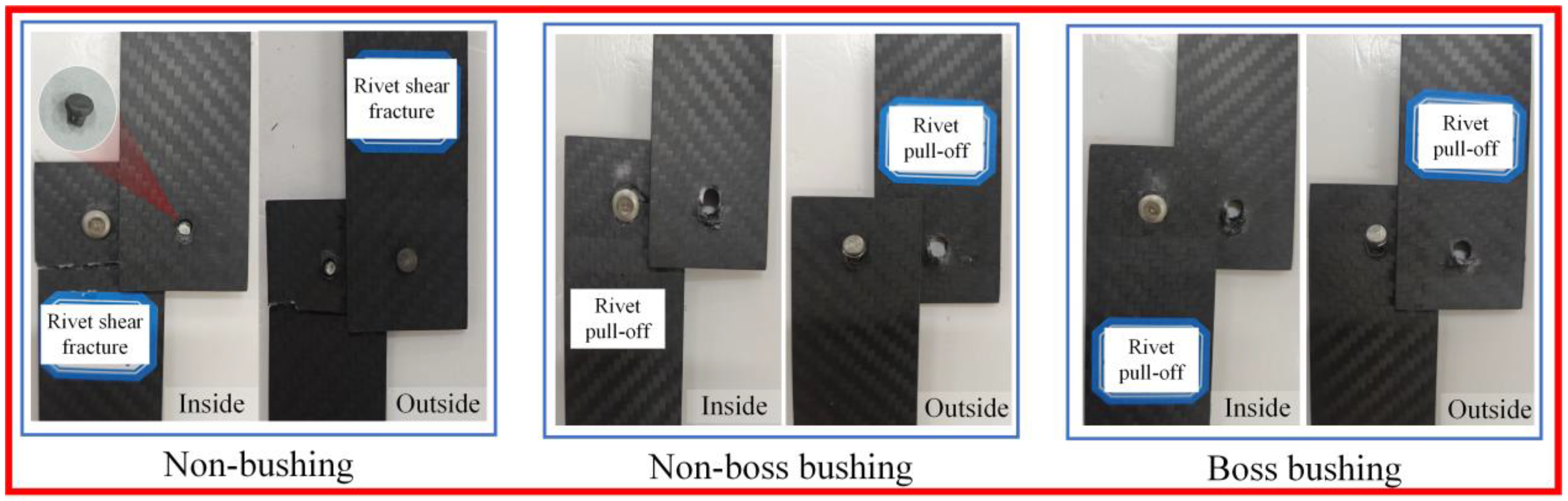
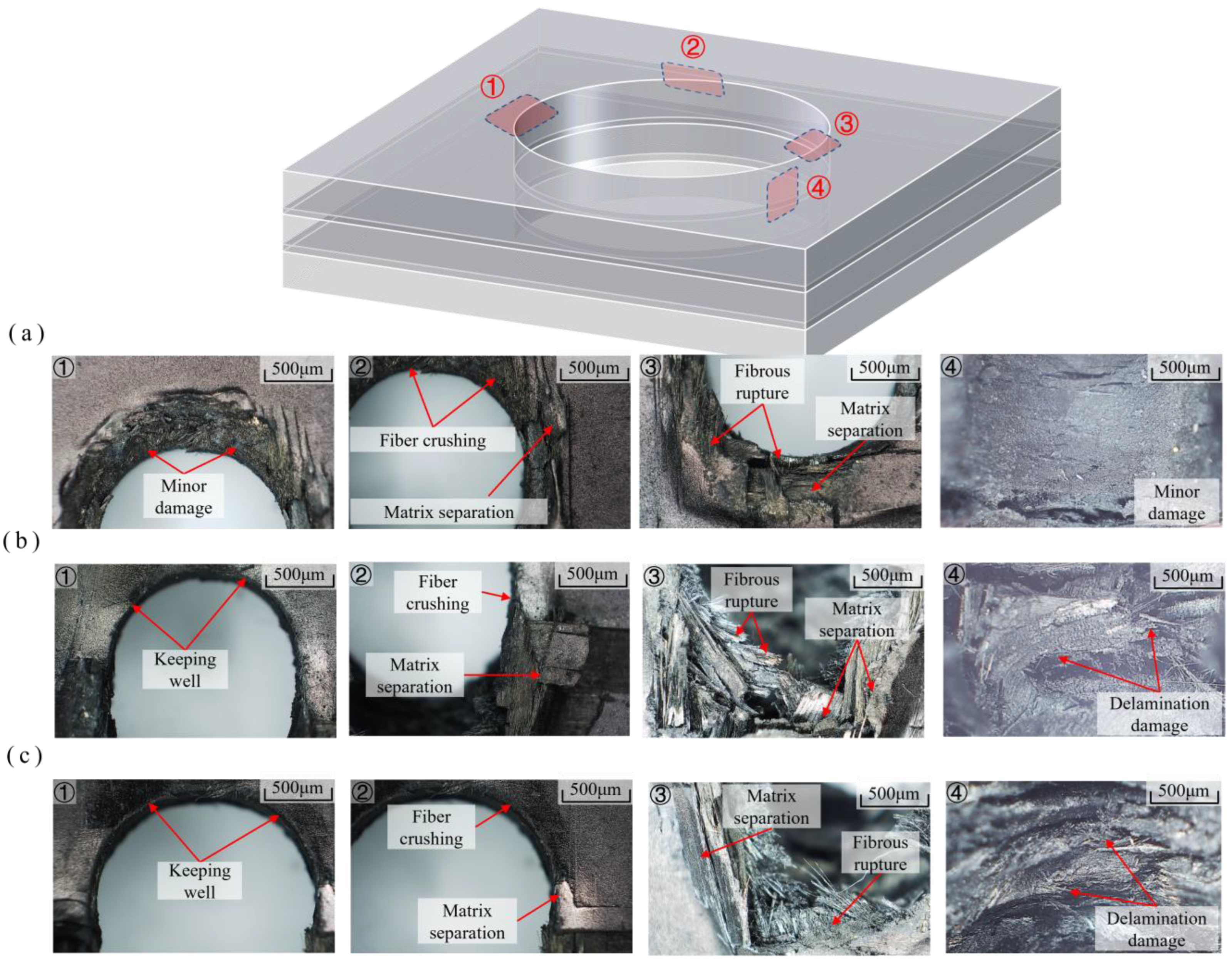
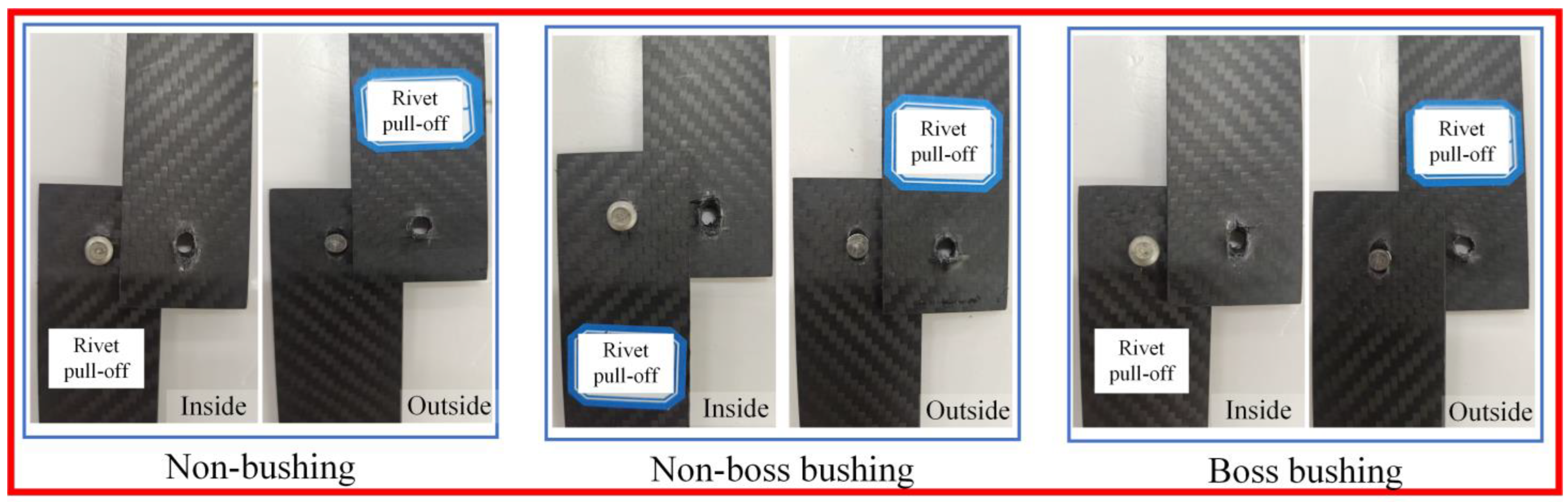
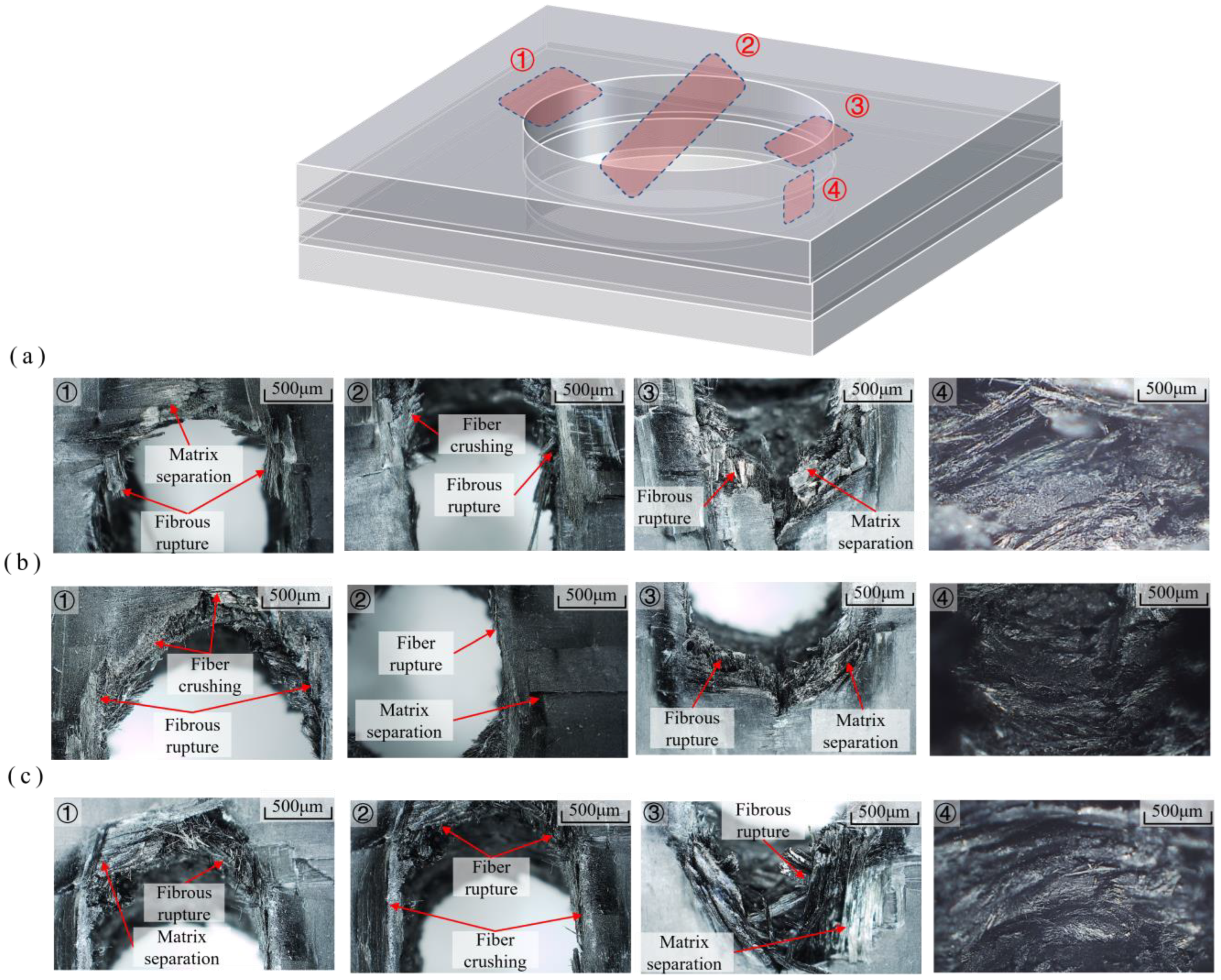
4.3. Tensile Test Failure Mode

In the tension-shear test, the failure modes of the three sets of riveted specimens are shown in Figure 13. The failure mode of riveted specimens without bushings is rivet shear fracture. This is because the rivet has low strength and poor plasticity, which causes the rivet to rupture directly under small shear displacement. The final failure mode for the non-boss bushing and boss bushing schemes is rivet pull-off failure. In the early stage of the test, the bushing riveting scheme showed local crush damage to the hole wall. As the damage further accumulated, the specimen first suffered shear failure, and finally led to pull-off failure of the rivet. In addition, the rivet holes of the upper and lower CFRP plates are significantly deformed, and significant tear damage and delamination damage occurred on the laminate on the extrusion side of the nail holes. At the same time, the rivet is bent and deformed, and the bushing is warped.
The RH-2000 ultra-depth microscope system is used to observe and analyze the microscopic morphology of tensile failure under three riveting schemes. Figure 14a–c show the microscopic characteristics of CFRP structures non-bushings, non-boss bushings, and boss bushings during tensile failure. The typical failure locations are marked as ①, ②, ③, and ④, respectively.
Observed from the ① position in Figure 14a–c, the microstructure of the upper-end face of the CFRP structure is similar, and no serious crush damage occurs. However, the crush damage of the non-bushing scheme in this area is significantly more serious than that of the bushing scheme. This position is a direct damage caused by the riveting and forming process. Therefore, the bushing can improve the damage caused by the riveting forming process to some extent. At the ② position, the fibers and resin in this area are crushed under the extrusion force. At the ③ position, as the tensile displacement increases, the riveting hole is elongated and the fiber is cut, which causes the matrix separation. The limit displacement of the bushing component is greater than that of the non-bushing component, so the damage to the CFRP hole circumference is more severe in Figure 14a–c ②③. In position ④, observe the wall of the CFRP hole. Since the failure form of the non-bushing riveting scheme is rivet shear fracture, the damage to the hole wall is relatively small. However, the failure form of the bushing riveting scheme is rivet pull-off, and serious delamination damage, fiber fracture, and matrix separation appear on the hole wall.

5. Hysteretic Test Results and Analysis

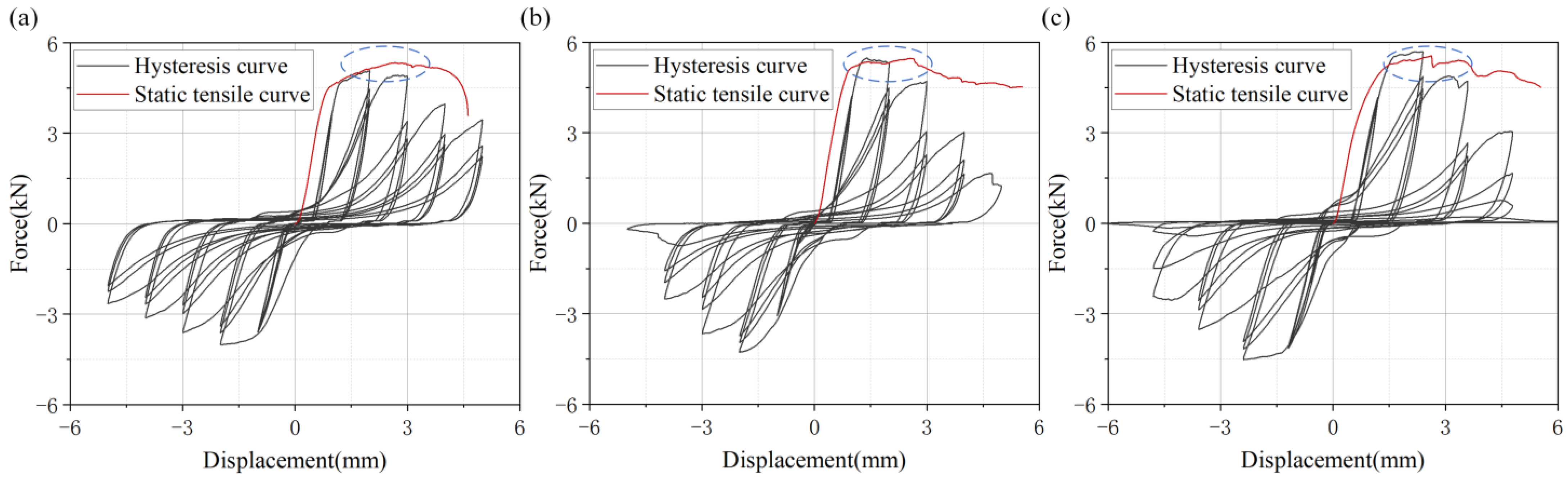
5.1. Hysteretic Response Analysis

As shown in Figure 15a, in the hysteretic test, the maximum tensile load of the non-bushing riveting scheme was 5.078 kN, and the maximum compressive load was 4.016 kN. As shown in Figure 15b, the maximum tensile load of the non-boss bushing riveting scheme is 5.357 kN, and the maximum compressive load is 4.485 kN. As shown in Figure 16c, the maximum tensile load of the boss bushing riveting specimen in the hysteretic test is 5.689 kN, and the maximum compressive load is 4.525 kN. The maximum tensile loads of the non-boss bushing and the boss bushing riveting schemes are increased by 5.49% and 12.03% compared with the non-boss bushing schemes. The two sets of non-bushing riveting and non-boss bushing riveting schemes lack boss protection during the test. Therefore, under repeated tension and compression, the maximum tensile load of the hysteretic test decreases compared with the tensile test due to the rivet squeezing the upper and lower laminates (as shown by the blue circle in Figure 15). However, under static tensile and hysteretic tests, the ultimate displacement and maximum tensile load test results of the boss bushing test scheme are similar. The specific parameters are shown in Table 5.

5.2. Failure Mode Analysis

The tensile failure modes of the three riveting methods are shown in Figure 16. When the load is loaded to 60%–80% of the maximum tensile load, the rivet hole gradually deforms and the rivet begins to be pulled off. The failure mode of the three riveted specimens in the hysteretic test was rivet pull-off. Compared with the monotonic tensile test, the damage around the rivet hole is more serious.
Figure 17a–c show the microscopic morphology of the CFRP structures’ non-bushings, non-boss bushings, and boss bushings during failure. The typical failure locations are marked as ①, ②, ③, and ④, respectively.
It can be seen from the ① positions in Figure 17a–c that the upper-end laminated plates of the CFRP structures under the three riveting schemes have certain similarities in the microscopic forms of failure. This location suffers severe fiber compression and matrix separation, but the extent of damage to the boss bushing is significantly better than the other two schemes. At the ② position, the fibers and resin are crushed under the action of cyclic extrusion force, causing severe fiber breakage and matrix separation. At the ③ position, the limit state of the rivet pull-off causes the maximum tensile displacement, resulting in the most serious damage there. Observation from Figure 17a–c ②③ shows that the non-bushing boss has less damage than the non-bushing. The limit displacement of the boss bushing component is large, so the damage around the hole is serious. However, the boss bushing is damaged similar to that of the non-bushing component. Therefore, the bushing component provides certain protection to the hole circumference. By observing location ④, it was found that severe delamination damage, fiber breakage, and matrix separation occurred in the hole walls of all scenarios. However, the damage of the CFRP hole wall with the bushing scheme is less than that of the non-bushing scheme, indicating that the bushing has a certain protective effect on the hole wall.

6. Conclusions

This study studied the mechanical properties of three riveting methods of CFRP structures (non-bushing, non-boss bushing, and boss bushing) under monotonic and cyclic loads. Through the simulation and test results, the following conclusions can be drawn:
(1) The simulation results show that the bushing riveting scheme can uniformly distribute the stress on the hole wall, thereby improving the interlayer damage of the upper hole wall of the composite material. It shows that the bushing scheme can improve the overall strength of the riveting part.
(2) In the tensile test, the load-displacement curve of the riveted specimen shows an obvious linear growth stage, damage evolution stage, and failure stage. However, compared to riveted specimens with bushings, the non-bushings riveted specimens have a rapid failure stage and a lower ultimate load due to the lack of bushing protection. The maximum tensile load of the non-boss bushing and boss-bushing riveting schemes is increased by 2.49% and 4.03% compared with the non-bushing scheme. In the hysteretic test, the maximum tensile loads of the non-boss bushing and the boss bushing riveting schemes are increased by 5.49% and 12.03% compared with the non-boss bushing schemes.
(3) In the tensile test, the failure mode for the non-bushing scheme is rivet shear fracture, and the bushing scheme is rivet pull-off. In the hysteretic test, the failure mode of the three schemes is rivet pull-off. In the non-bushing scheme, the damage distribution in the CFRP hole wall is uneven. The damage to the upper CFRP plate mainly concentrates on the rivet extrusion side. In the bushing riveting scheme, the damage to the CFRP hole wall and the damage to the upper plate are improved compared with the non-bushing scheme.

Author Contributions

Conceptualization, D.W. and Y.Z.; methodology, D.W.; software, D.W. and B.W.; formal analysis, D.W. and C.S.; investigation, M.X. All authors have read and agreed to the published version of the manuscript.

Funding

This research received no external funding.

Institutional Review Board Statement

Not applicable.

Informed Consent Statement

Not applicable.

Data Availability Statement

Data are contained within the article.

Acknowledgments

Special thanks are extended to Lecturer Xingxing Wang from Suqian University of Mechanical and Electrical Engineering and Lecturer Ziyu Wang from the Institute of Mechanical Engineering at Anhui University of Technology for their guidance and assistance in this study.

Conflicts of Interest

The authors declare no conflicts of interest.

References

  1. Hong, J.; Xu, P. Electromagnetic Interference Shielding Anisotropy of Unidirectional CFRP Composites. Materials 2021, 14, 1907. [Google Scholar] [CrossRef]
  2. Melinda, A.P.; Higuchi, S.; Yoresta, F.S.; Yamazaki, Y.; Nhut, P.V.; Nuryanti, P.; Matsumoto, Y. Bending performance of laminated veneer lumber timber beams strengthened in the compression side with near-surface mounted CFRP plates. Case Stud. Constr. Mater. 2024, 21, e03418. [Google Scholar] [CrossRef]
  3. Duan, Z.; Liu, G.; Fan, X.; Chen, T. Study on cutting force performance and cutting mechanism of Carbon Fiber Reinforced Polymer (CFRP) composites. J. Adv. Mech. Des. Syst. Manuf. 2021, 15, 21–00193. [Google Scholar] [CrossRef]
  4. Xiang, X.; Xiao, C.; Lu, G.; Xie, Y.M.; Yang, H.; Zhang, J.; Ha, N. San Novel interaction effects enhance specific energy absorption in foam-filled CFRP tapered tubes. Compos. Struct. 2024, 343, 118288. [Google Scholar] [CrossRef]
  5. Xiao, X.; Shanyong, X.; Bin, F. The strength recovery effect of scarf bonding on the CFRP laminates with impact damage. Heliyon 2023, 9, e19143. [Google Scholar] [CrossRef]
  6. Liu, C.; Li, Y.; Cheng, Y.; Zhao, A.; Du, K.; Shi, Y.; Li, X.; Cheng, H. Investigation of stress distribution and damage behavior caused by forced installation of a composite bolted joint with a hole-location error. Chin. J. Aeronaut. 2024, 37, 201–217. [Google Scholar] [CrossRef]
  7. Jin, K.; Wang, H.; Tao, J.; Tian, J. Effect of the interference fit on the stress distribution and failure mode of a flat-head riveted GLARE joint. Compos. Struct. 2020, 235, 111788. [Google Scholar] [CrossRef]
  8. Zheng, Y.; Zhang, C.; Tie, Y.; Wang, X.; Li, M. Tensile properties analysis of CFRP-titanium plate multi-bolt hybrid joints. Chin. J. Aeronaut. 2022, 35, 464–474. [Google Scholar] [CrossRef]
  9. Yoo, S.-W.; Shin, J.; Choo, J.F. Evaluation of bond strength of helically ribbed CFRP bar connections as mechanical anchorage schemes. Case Stud. Constr. Mater. 2024, 20, e02826. [Google Scholar] [CrossRef]
  10. Liu, Z.; Wang, H.; Chen, Y.; Chai, D.; Hua, L. Interfacial enhancement of CFRP/titanium alloy bonding joint by constructing a 3D interconnected CNTs network. J. Mater. Res. Technol. 2023, 26, 4078–4092. [Google Scholar] [CrossRef]
  11. Hu, M.; Yue, N.; Groves, R.M. Damage Classification of a Bolted Connection using Guided Waves and Explainable Artificial Intelligence. Procedia Struct. Integr. 2024, 52, 224–233. [Google Scholar] [CrossRef]
  12. Iordachescu, M.; Valiente, A.; de Abreu, M.; Santos, P.; Scutelnicu, E. Environmentally assisted fatigue failure of a structural bolted-joint connection. Eng. Fail. Anal. 2022, 137, 106322. [Google Scholar] [CrossRef]
  13. Dong, S.; Liao, W.; Zheng, K.; Xue, F.; Sun, L. Hole surface strengthening mechanism and riveting fatigue life of CFRP/aluminum stacks in robotic rotary ultrasonic drilling. Chin. J. Aeronaut. 2023, 36, 471–484. [Google Scholar] [CrossRef]
  14. Lim, Y.C.; Jun, J.; Leonard, D.N.; Li, Y.; Chen, J.; Brady, M.P.; Feng, Z. Study of galvanic corrosion and mechanical joint properties of AZ31B and carbon-fiber–reinforced polymer joined by friction self-piercing riveting. J. Magnes. Alloys 2022, 10, 400–410. [Google Scholar] [CrossRef]
  15. Yang, M.; Xuan, H.; Qin, T.; Wang, Y.; Zhou, Y.; Zhang, W. Numerical and experimental study of the residual strength of CFRP laminate single-lap joint after transverse impact. Int. J. Adhes. Adhes. 2024, 130, 103593. [Google Scholar] [CrossRef]
  16. Jiang, H.; Gao, S.; Li, G.; Cui, J. Structural design of half hollow rivet for electromagnetic self-piercing riveting process of dissimilar materials. Mater. Des. 2019, 183, 108141. [Google Scholar] [CrossRef]
  17. Alves, L.M.; Afonso, R.M.; Martins, P. Double-sided self-pierce riveting of polymer sheets. J. Adv. Join. Process. 2021, 3, 100051. [Google Scholar] [CrossRef]
  18. Zhang, M.; Cao, Z.; Guo, Y.; Cao, Y.; Zheng, G.; Huo, L. Stress, damage, and fatigue performance analysis of CFRP/Al double-sided countersunk riveted joints with variable rivet-hole clearance. Int. J. Fatigue 2024, 186, 108385. [Google Scholar] [CrossRef]
  19. Qiu, X.Y.; Li, P.N.; Tang, L.Y.; Li, C.P.; Niu, Q.L.; Li, S.J.; Tang, S.W.; Ko, T.J. Determination of the optimal feed rate for step drill bit drilling CFRP pipe based on exit damage analysis. J. Manuf. Process. 2022, 83, 246–256. [Google Scholar] [CrossRef]
  20. Rao, Z.; Ou, L.; Wang, Y.; Wang, P.-C. A self-piercing-through riveting method for joining of discontinuous carbon fiber reinforced nylon 6 composite. Compos. Struct. 2020, 237, 111841. [Google Scholar] [CrossRef]
  21. Okayasu, M.; Naito, R. Mechanical properties of the riveted connecting forming of CFRP plates. Int. J. Mater. Form. 2018, 11, 225–232. [Google Scholar] [CrossRef]
  22. Liu, Y.; Zhuang, W.; Luo, Y.; Xie, D.; Mu, W. Joining mechanism and damage of self-piercing riveted joints in carbon fibre reinforced polymer composites and aluminium alloy. Thin-Walled Struct. 2023, 182, 110233. [Google Scholar] [CrossRef]
  23. Tarpani, A.; Barreto, T.A.; Tarpani, J.R. Fatigue failure analysis of riveted fibre-metal laminate lap joints. Eng. Fract. Mech. 2020, 239, 107275. [Google Scholar] [CrossRef]
  24. Borba, N.Z.; Körbelin, J.; Fiedler, B.; dos Santos, J.F.; Amancio-Filho, S.T. Low-velocity impact response of friction riveted joints for aircraft application. Mater. Des. 2020, 186, 108369. [Google Scholar] [CrossRef]
  25. Cao, Z.; Zuo, Y. Electromagnetic riveting technique and its applications. Chin. J. Aeronaut. 2020, 33, 5–15. [Google Scholar] [CrossRef]
  26. Wang, X.; Qi, Z.; Chen, W.; Xiao, Y. Study on the effects of transverse ultrasonic vibration on deformation mechanism and mechanical properties of riveted lap joints. Ultrasonics 2021, 116, 106452. [Google Scholar] [CrossRef]
  27. Wang, J.; Zhu, C.; Yang, Y.; Zhang, Y.; Bi, Y. Effect of riveting displacement on the mechanical behavior of CFRP bolted joints with elliptical-head non-lug self-locking rivet nut. Int. J. Adv. Manuf. Technol. 2023, 125, 2161–2182. [Google Scholar] [CrossRef]
  28. Feng, J.; Zhang, J.; Jin, W.; Liao, R. Damage evolution modeling of CFRP/Al single-lap screw type blind riveted joints during realistic installation process. Compos. Struct. 2024, 337, 118023. [Google Scholar] [CrossRef]
  29. Zhang, M.; Cao, Z.; Cao, Y.; Zheng, G.; Guo, C.; Wang, Y. Investigation on interference and damage behaviours of electromagnetic riveted double-sided countersunk 30CrMnSiA/CFRP joints. Compos. Struct. 2024, 329, 117824. [Google Scholar] [CrossRef]
  30. Qi, Z.; Zhang, Z.; Xiao, Y.; Wang, X. Analysis of Plastic Improvement and Interference Behavior in Current-Assisted Riveting of CFRP Laminates. Materials 2022, 15, 1673. [Google Scholar] [CrossRef]
  31. Shao, C.; Lin, J.; Guan, Y.; Quan, D.; Chen, L.; Zhang, C.; Zhao, G. Low-frequency vibration assisted self-pierce riveting (LV-SPR) of carbon fiber reinforced composite and aluminum alloy. Int. J. Mach. Tools Manuf. 2024, 197, 104147. [Google Scholar] [CrossRef]
  32. Yang, Z.; Jiang, R.; Zuo, Y. Riveting damage behavior and mechanical performance assessments of CFRP/CFRP single-lap gasket-riveted joints. Eng. Fail. Anal. 2023, 149, 107253. [Google Scholar] [CrossRef]
  33. Qu, L.; Li, P.; Lv, G.; Li, J.; Luo, X. Rivet Structural Design and Process Optimization for the Double-Sided Countersunk Riveting of Composite Wedge Structures. Aerospace 2024, 11, 165. [Google Scholar] [CrossRef]
  34. QJ 782A-2005; Quality Standard for Aquatic Products. Standardization Administration of China: Beijing, China, 2005.
  35. ASTM D1761-12; Standard Test Method for Mechanical Fasteners in Wood. ASTM International: West Conshohocken, PA, USA, 2012.
  36. ISO/TC165; ISO 16670 Timber Structures-Joints Made with Mechanical Fasteners-Quasi-Static Reversed-Cyclic Test Method. The International Organization for Standardization: Geneva, Switzerland, 2003.
  37. Wang, X. Multi-Scale Analyses of Damage Evolution in Woven Composite Materials; Nanjing University of Aeronautics and Astronautics: Nanjing, China, 2007. [Google Scholar]
  38. GB/T 3620.1-2016; Metal Fasteners—Mechanical Properties of Fasteners—Part 1: Metric Coarse Thread Bolts, Screws and Nuts. Standards Administration of China: Beijing, China, 2016.
  39. Su, H.; Deng, K.; Yang, D.; Zhan, X.; Xie, Z.; Qin, J.; Ma, L. Performance and failure analysis of perforated CFRP/aluminum alloy bonding and self-piercing riveting hybrid joints. Eng. Fail. Anal. 2024, 156, 107803. [Google Scholar] [CrossRef]
  40. Li, W.; Guo, S.; Giannopoulos, I.K.; He, S.; Liu, Y. Strength enhancement of bonded composite laminate joints reinforced by composite Pins. Compos. Struct. 2020, 236, 111–116. [Google Scholar] [CrossRef]
Figure 1. The single rivet single lap specimen.
Coatings 14 01076 g001
Figure 2. Three riveting methods for CFRP structures: (a) non-bushing; (b) non-boss bushing; (c) boss bushing.
Coatings 14 01076 g002
Figure 3. Loading system for hysteretic test.
Coatings 14 01076 g003
Figure 4. Schematic diagram of test equipment and fixture.
Coatings 14 01076 g004
Figure 5. Three-dimensional finite element model of boss bushing riveting.
Coatings 14 01076 g005
Figure 6. Damage law based on bilinear softening.
Coatings 14 01076 g006
Figure 7. Simulation stress nephograms of three riveting methods: (a) non-bushing; (b) non-boss bushing; (c) boss bushing.
Coatings 14 01076 g007
Figure 8. Simulated stress distribution around the hole with three riveting methods: (a) non-bushing; (b) non-boss bushing; (c) boss bushing.
Coatings 14 01076 g008
Figure 9. The CFRP riveting specimen.
Coatings 14 01076 g009
Figure 10. Relationship between pressing and riveting force and tool die depression displacement: (a) overall curve; (b) curve after displacement reaches 2 mm.
Coatings 14 01076 g010
Figure 11. Determination method of yield displacement and limit displacement.
Coatings 14 01076 g011
Figure 12. Static tensile test force-displacement curve of CFRP riveted specimens: (a) non-bushing; (b) non-boss bushing; (c) boss bushing; (d) comprehensive curve of three schemes of specimens.
Coatings 14 01076 g012
Figure 13. Tension-shear failure modes of three riveting methods.
Coatings 14 01076 g013
Figure 14. Micrographs of tensile failure of three riveting methods: (a) non-bushing; (b) non-boss bushing; (c) boss bushing.
Coatings 14 01076 g014
Figure 15. The hysteretic curve of CFRP riveted specimen: (a) non-bushing; (b) non-boss bushing; (c) boss bushing.
Coatings 14 01076 g015
Figure 16. Hysteretic test failure modes of three riveting methods.
Coatings 14 01076 g016
Figure 17. Micrographs of failure in the hysteretic test of three riveting methods: (a) non-bushing; (b) non-boss bushing; (c) boss bushing.
Coatings 14 01076 g017
Table 1. The mechanical property parameters of T700 carbon fiber reinforced composites.
E11/GPaE22/GPaE33/GPaG12/GPaG13/GPaG23/GPav12v13v23
16412125.25.25.20.350.350.45
XT/MPaXC/MPaYT/MPaYC/MPaZT/MPaZC/MPaS12/MPaS13/MPaS23/MPa
27241690102254102254254290290
Notes: E11, E22, E33-Elastic modulus; G12, G13, G23-Shear modulus; v12, v13, v23-Poisson’s ratio; XT-Longitudinal tensile strength; XC-Longitudinal compression strength; YT, ZT-Transverse tensile strength; YC, ZC-Transverse compression strength; S12, S13, S23-Shear strength.
Table 2. The mechanical properties parameters of Ti-45Nb alloy rivets and bushings.
MaterialModulus/GPaPoisson’sDensity/(kg∙m−3)Tensile Strength/MPaYield Strength/MPa
rivet620.345.70570425
liner620.345.70570425
Table 3. The interlayer performance parameters of composite materials.
GIC/(mJ∙mm−2)GIIC/(mJ∙mm−2)GIIIC/(mJ∙mm−2)tn/MPats/tt/MPaKn/Ks/Kt/MPa
0.351.451.4560801 × 105
Notes: GΙC-Critical energy release rate in mode I delamination; GΙΙC-Critical energy release rate in mode II delamination; GΙΙΙC-Critical energy release rate in mode III delamination; tn, ts, tt-Interface strength; Kn, Ks, Kt-Initial interface stiffness.
Table 4. Static tensile test results.
Specimen IDPmax/kNu/mmPy/kNy/mm
Non-bushing5.3344.5484.7841.263
Non-boss bushing5.4676.0145.1891.040
Boss bushing5.5495.6185.0331.275
Table 5. Hysteretic test results.
Specimen IDPmax,+/kNPmax,−/kNu,+/mmu,−/mmPmax/kNu/mm
Non-bushing5.0784.0162.9512.9265.3344.548
Non-boss bushing5.3574.4852.9712.9855.4676.014
Boss bushing5.6894.5253.3493.5885.5495.618
Disclaimer/Publisher’s Note: The statements, opinions and data contained in all publications are solely those of the individual author(s) and contributor(s) and not of MDPI and/or the editor(s). MDPI and/or the editor(s) disclaim responsibility for any injury to people or property resulting from any ideas, methods, instructions or products referred to in the content.

