Abstract
Mobile microrobots are of great scientific significance. However, external actuation and control methods are still challenging to conduct. We present a single carbon nanocoil (CNC) microrobot induced by an NIR laser beam, capable of light-driven locomotion and photothermal actuation. This research demonstrates that CNC-based microrobots roll away from the focal spot when the laser beam is focused near the CNC. The maximum translational distance of a CNC microrobot increases with an increase in laser power, and the direction of motion is guided by controlling the focusing position of NIR. CNC-based microrobots can load and transport multiple cells under NIR light irradiation, resulting from the temperature gradient generated by photothermal conversion, which causes thermophoresis. The hydrophobic surface and unique helical structure of CNCs are beneficial to the underwater drag reduction in CNC microrobots’ motion and the adhesion of cells on CNC microrobots. Therefore, CNC microrobots, as cell vectors driven by a laser beam, may find applications in a wide range of biomedical applications. In addition, the rotation of a CNC powered by a laser beam provides promising prospects for the future of nanomechanical devices using a carbon nanocoil as a micro/nanomotor.
1. Introduction
With the development of micro/nano technology and the demands of human beings for medical treatment and a micro-manufacturing system, microrobot technology has developed rapidly. It has wide application prospects in minimally invasive treatments in the human body and microchip labs due to its small size and its ability to work in a tiny space. In minimally invasive treatments, microrobots can deliver targeted drugs, perform local radiation therapy and thermal therapy and realize operations such as transferring cells [1,2,3,4], performing minimally invasive surgery in aspects of intraocular, cardiovascular or endaural environments [5]. A microrobot can assemble a micro-system, transfer a micro-device and so on in a microchip lab [6]. Owing to its small-size limitations, microrobots, unlike macrorobots [7], need an external source to supply power for their actuation. Therefore, actuation sources play a critical role in driving the motion of microrobots. However, most actuation sources, such as an electrostatic field [8], magnetic field [9] and thermal field adapted to microrobots in sub-millimeter sizes [10], require complex hardware and a custom-made microrobot. Magnetic field-controlled microrobots have become a research hotspot in recent years. However, a magnetically controlled microrobot requires magnetic materials to be encapsulated into its structure or coated on its surface to modify the microrobot, which is unfavorable for cells involved in vivo biomedical applications. And the configuration is complicated for microrobots driven by magnetic fields.
Light, as an external energy source, is capable of driving the motion of microrobots, with the advantages of non-contact, a fast response time, safety, ease of application, and wireless and remote manipulation. Additionally, the light-driven method does not require additional magnetization processing for microrobots. The motion of micro/nanomotors driven or guided by light has been widely studied for its potential use in various applications, such as environmental remediation, hydrogen evolution and targeted drug delivery [11,12,13,14,15]. Wei and co-workers reported that an ultraviolet light beam can cause fully organic colloidal particles of a hyperbranched polymer with a spiropyran terminal to swim towards a UV source [16]. Xuan and co-workers developed a near-infrared (NIR) light-powered membrane-coated nanomotor, based on the photothermal effect, to thermomechanically percolate cell membranes for cancer therapy [17]. Sen and co-workers reported that TiO2 nanomotors are driven by photocatalytic fuel decomposition or photocatalytic degradation reactions [18]. Philipp Harder and co-workers reported an optically controlled and mobile soft microrobot for the thermal stimulation of single mammalian cells [19]. However, due to the limitation of the microrobot’s shape and material, the major factors hampering the prospective use of such light-driven microrobots in potential applications are its incapability of carrying functional cargos and its lack of biocompatibility for biological organizations.
Carbon nanocoils (CNCs), as quasi-one-dimensional nanomaterials, have excellent physical and chemical properties (e.g., mechanical and thermal properties, good dispersibility, and hydrophobicity) [20,21,22,23,24]. In recent years, functionalized CNCs have garnered increasing attention due to their excellent NIR response, which is derived from the special helical structure and larger specific surface areas of a single CNC [25]. In particular, its special helical structure and hydrophobic surface are beneficial to the underwater drag reduction in CNC motion [26,27]. Moreover, CNCs, having an excellent biocompatible nature, have been studied in the biological medical field and nanoelectromechanical systems (MEMSs) [28,29,30].
In this paper, we present a helical microrobot, which is based on a single CNC and is driven and guided by an NRI laser beam. Additionally, the ability of the CNC-based microrobot to load and transport cells in water is verified by controlling the position of NRI irradiation. Driving the CNC microrobots by light is demonstrated to be a new design and method for a mobile microrobot, with the characteristics of non-physical contact and a fast response time and with the function of loading and transporting yeast cells.
2. Materials and Methods
The CNCs used in this experiment were synthesized by a thermal chemical vapor deposition method [31]. An iron film of 50 mm thickness was formed on an indium tin oxide (ITO) substrate as the catalyst precursor by a magnetron sputtering system (JCP-200, Technol, Beijing, China). Acetylene gas as a carbon source and argon as the shielding gas are introduced into the reaction furnace, with a flow rate of 15 sccm and 245 sccm, respectively, for 1 h (with a reaction temperature of 710 °C). Then, CNCs with an average fiber diameter of 250 nm, a coil diameter of 500 nm and an average pitch of 450 nm were synthesized. In our experiment, in order to obtain a single CNC immersed in water, CNC powder was scraped into water and then treated by an ultrasonic method at 30 °C for 40 min.
The laser optical path system (optical tweezers system, LOT II, ZHONGKE Optical Tweezers Technology Co., Ltd., Beijing, China) used in the experiment is shown in Figure 1. The wavelength of the laser source used in the experiment is 1064 nm and the laser power output is 0–3 W (with a focus spot diameter of about 4 μm). The laser beam was focused near a single CNC in a transparent chamber in the sample stage through a 60× objective lens system (1.25 numerical aperture). The process of light-driven CNC motion is monitored by a charge-coupled device (CCD) camera.
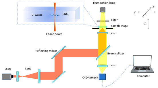
Figure 1.
Experimental setup. The NIR laser beam is focused in the transparent chamber through the objective lens to drive a single CNC microrobot in deionized water (DI water).
3. Results
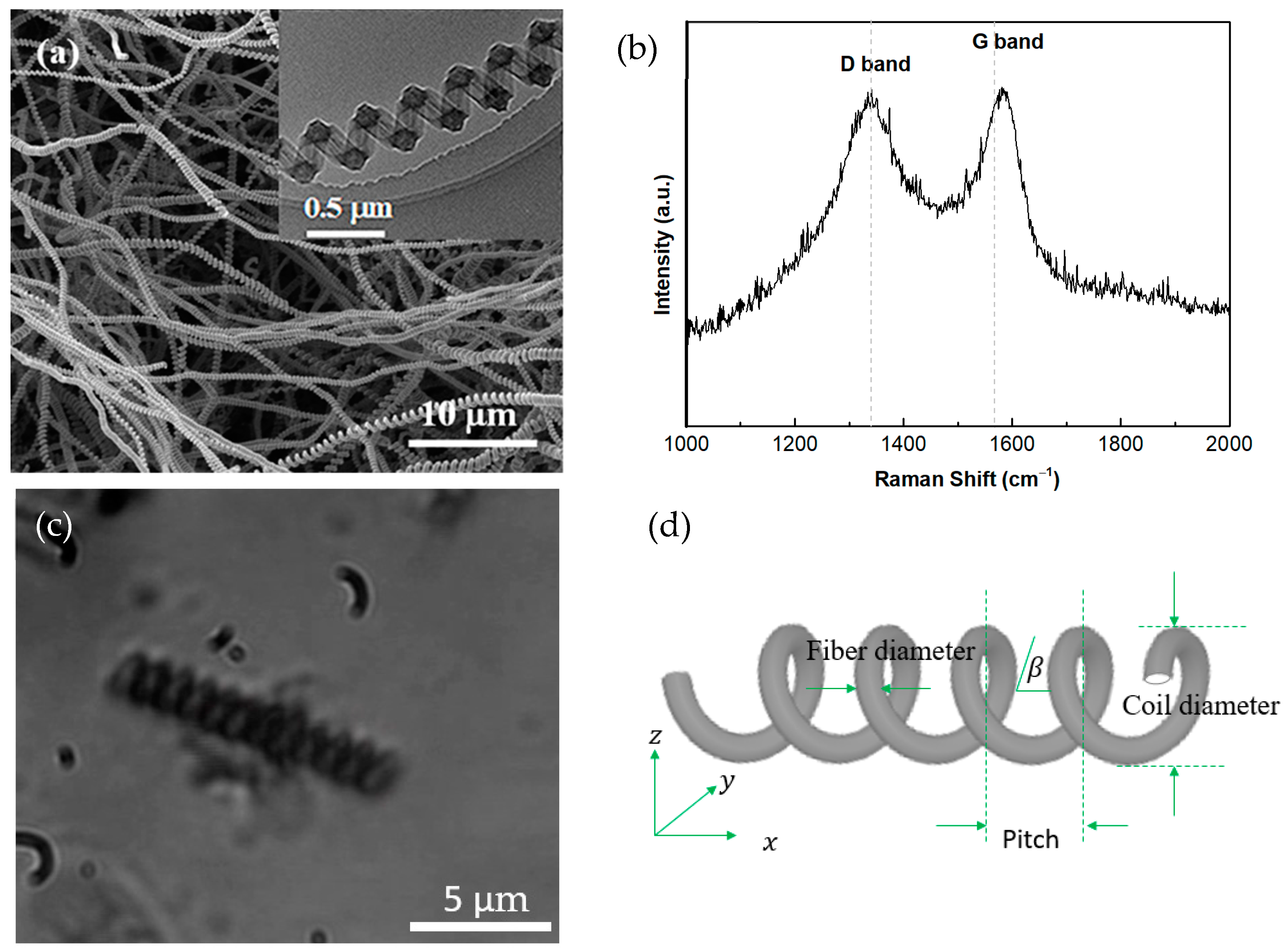
The fabricated CNCs are characterized by a scanning electron microscope and a Raman spectrometer (Invia, Renishaw, Gloucestershire, UK). Figure 2a (SEM) and Figure S1 (TEM) show the morphology of CNCs with a unique helical structure. The Raman spectrum of CNCs indicates a D band at 1336 cm−1 and a G band at 1589 cm−1, which represents the defects in the lattice and the SP2-hybridized in-plane stretching vibration of C atoms, respectively, as shown in Figure 2b. The optical image and the schematic diagram of a microrobot are shown in Figure 2c and Figure 2d, respectively.
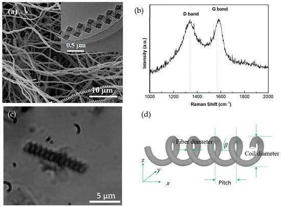
Figure 2.
(a) SEMs of CNC agglomeration and a single CNC in the upper right corner. (b) Raman spectrum of CNCs. (c) Optical image and (d) schematic diagram of a CNC microrobot.
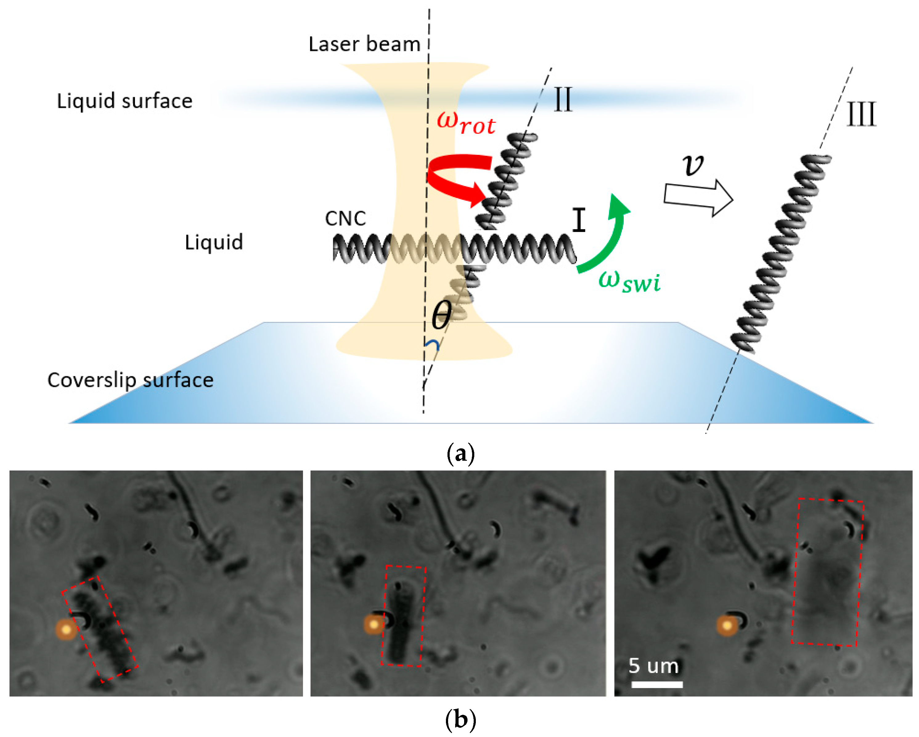
A single CNC microrobot near the focus is driven by the focused NIR laser beam (with a laser power of 0.8 mW), as shown in Figure 3b (also see Video S1 in the Supplementary Materials). Figure 3a shows that a single CNC microrobot has three modes of motion under the focusing laser beam irradiation: swinging around the focal spot of the laser beam, rotating rapidly on its own helix axis and translating away from the focal spot. According to the theory of optical tweezers [32], the reflection effect of CNCs on the incident light causes a scattering force acting on the CNC due to the refractive index of the CNC being greater than the refractive index of the surrounding liquid, and the direction of the scattering force is along the propagation direction of the light, which makes the section of the CNC irradiated by laser beam always move towards the focal point. When the CNC is below the focus, the CNC is pulled towards the focal point along the optical axis. When the CNC is above the focus, the CNC is pushed into the focal point along the optical axis. Therefore, the CNC deviates from the original orientation at an angle of θ between the helix axis of the CNC and the optical axis when the scattering force acts on the CNC, as shown in Figure 4a.
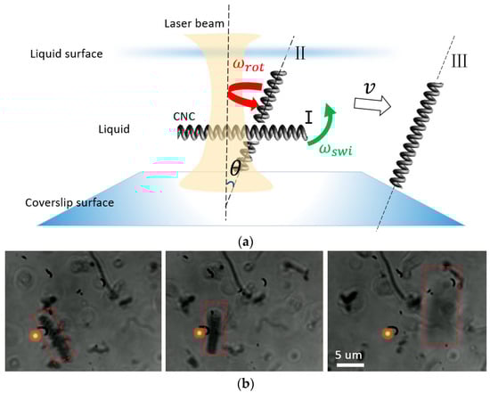
Figure 3.
(a) Schematic diagram of a light-driven CNC rotor. Procedures I to III represent a change in the position of CNC robot caused by laser beam irradiation. (b) Optical images of a light-driven CNC at various time intervals under the laser beam irradiation with a power of 0.8 mW. Red dotted square areas describe the position of the CNC. The yellow dots represent the laser focus position. The CNC is 8 μm in length.
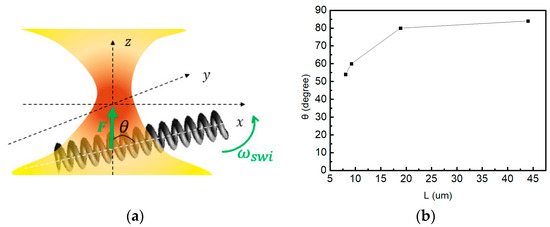
Figure 4.
(a) Schematic diagram of the CNC irradiated by a focusing laser beam. (b) The relation between CNC length and the angle, θ, in Figure 4a (laser power of 0.8 mW).
Moreover, the angle, θ, between the helix axis of the CNC and the optical axis is related to the CNC length. Figure 4b shows that the longer the CNC is, the larger the angle, θ, is. According to Equation (1),
where J, and represent the rotational inertia, mass and length of the CNC, respectively. When the scattering force acting on a single CNC is constant, a longer CNC with a larger moment of inertia is the primary cause for the result noted above. Compared to the shorter CNC, the longer CNC obtains the lower angular velocity , making the CNC swing around the laser beam focus, which leads to a larger angle, θ, simultaneously.
On the basis of the theory model proposed by Petr [33], the excitation of CNC phonons by light, and the subsequent relaxation, can be described with the simplified Hamiltonian:
The first term is the energy of the phonon modes of the CNC = (band, k), where and denote the produce operator and annihilation operator of the CNC, respectively, and denotes the second quantization frequency for mode . The second term describes the coupling of the chosen IR optical phonons, with operators and , to the light intensity of the same polarization, which denotes the interaction between the light and the CNC. denotes the interaction strength between the light and phonons of the CNC. The third term denotes the decay of these IR phonons, with wave vectors k ≈ 0, into phonon pairs with opposite wave vectors ±k, which most likely come from the same acoustical branch [34,35]. These cannot carry angular quasimomentum L, which is passed to the CNC body by Umklapp processes. The resulting CNC rotation is predominantly damped by scattering with molecules, as described in [36]. Therefore, the reason for CNC rotation is that the angular momentum of incident photons is resonantly transferred to CNC phonons and passed to the CNC body through Umklapp scattering. The transferred angular momenta force a torque on the CNC body, leading the CNC to rotate on its own helix axis. When the helix axis of the CNC deviates from the NIR optical axis at an angle of θ, as shown in Figure 5, the photons’ angular momenta which is transferred to CNC phonons are a component of the total photons’ angular momenta, leading to a reduced torque on the CNC. According to the law of rotation [37,38,39], the lower the torque, the lower the angular velocity for rotation on its own helix axis.
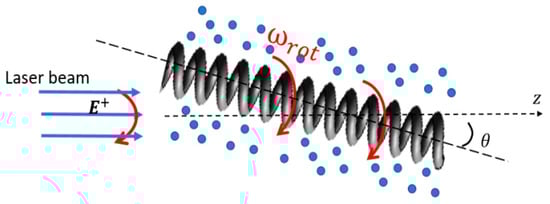
Figure 5.
Schematic diagram of helical CNC rotating with angular velocity under laser beam irradiation.
On the other hand, the asymmetrically helical surface of a CNC can help create a local dynamic gradient in fluid. A CNC microrobot’s rotating motion can also be explained by the maldistribution of temperature and the thermal slip flow field surrounding the CNC microrobot, which is attributed to the highly efficient NIR photothermal conversion and the asymmetrically helical structure of the CNC. The absorption of light at the asymmetrically helical surface of a CNC creates a local temperature gradient, which in turn causes the CNC to rotate.
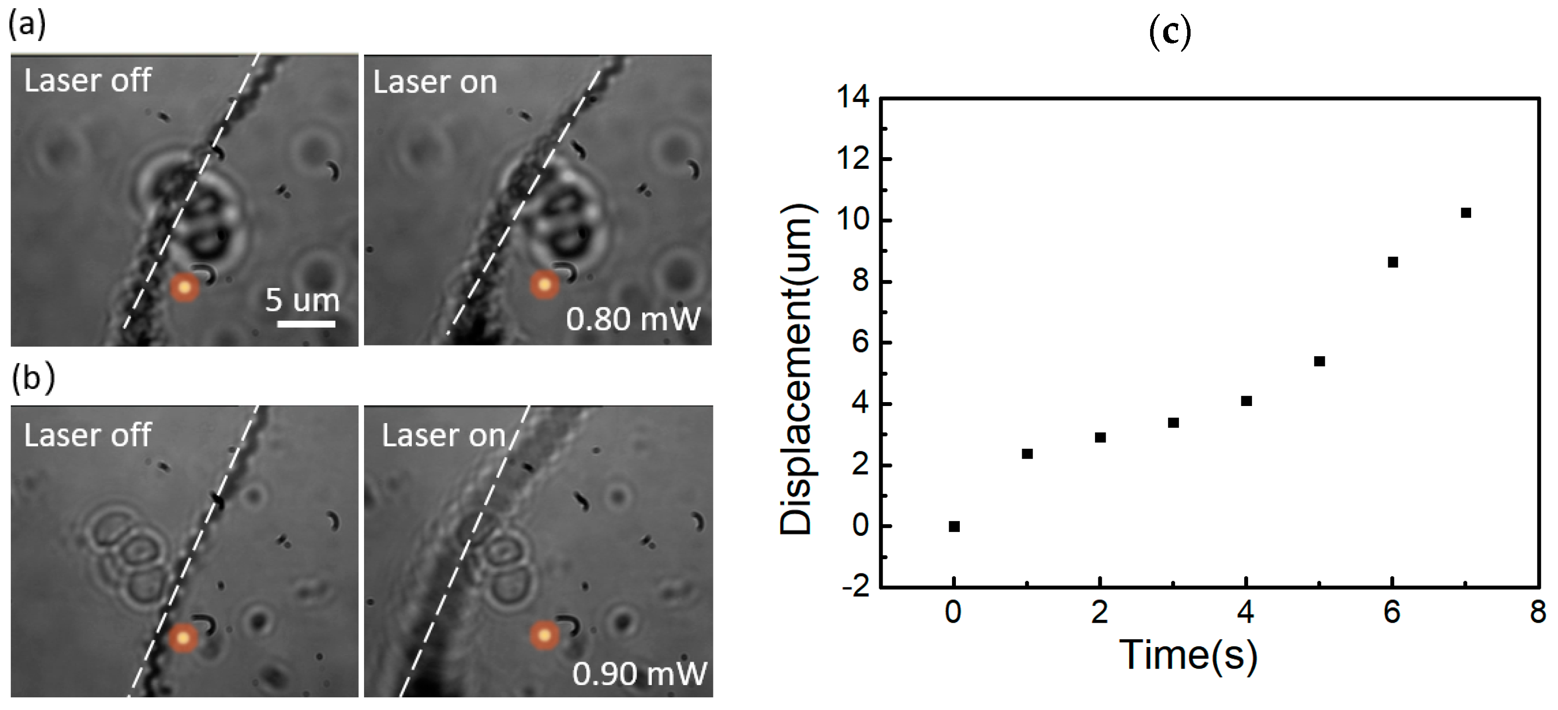
Figure 6a shows that the translational displacement of the CNC microrobot reaches a maximum of 5 μm at 7 s (with a laser power of 0.8 mW). Figure 6b shows that the translational displacement of the CNC microrobot reaches a maximum of 9 μm at 5 s (with a laser power of 0.9 mW). This phenomenon demonstrates that increasing the power of the laser beam induces faster microrobot rotation and a stronger convectional flow on the side of the CNC irradiated, leading the CNC microrobot to roll away from the focusing area due to the viscous action of water stiction. When the CNC robot is irradiated by a laser with a higher power, more angular momenta of photons are transferred to CNC phonons, leading to a larger torque that causes the CNC to rotate with a higher angular velocity . After the CNC robot moves away from the focusing area, the torque caused by the photon angular momentum fades away. Meanwhile, the CNC robot with a higher angular velocity, , travels a greater distance, i.e., the max translational displacement. Figure 6c shows the relationship between the translational displacement and the laser irradiation time. The translational displacement of CNC microrobots increases with an increase in the NIR irradiation time (with a laser power of 0.96 mW). From Figure 6c, obvious variation in the slope of the curve is observed at 2 s and 5 s. In the initial stage of CNC motion, the translational motion of the CNC away from the focus is relatively fast. Then, it gradually slows down after 2 s and picks up again at 5 s, nearly matching its initial stage. First, after a 2 s laser irradiation, the CNC microrobot reaches the area outside the focusing area. The drag torque is the dominating torque type, which decelerates the rotational and forward velocity of the CNC robot. Significant evidence indicates that the DI water exhibits strong absorption of near-infrared light. When a laser beam is focused on water, photon energy is absorbed by the water and converted into thermal energy. The concentrated thermal energy accumulated around the focusing area is released to heat the surrounding water over time under continuous laser irradiation. Consequently, after a 5 s laser irradiation, an additional force emerges from the gradient of the temperature, forcing the CNC robot to go forward.
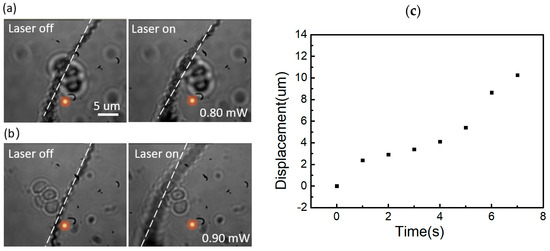
Figure 6.
(a,b) are the max translational displacement of CNC microrobot driven by the different power of laser. The dashed white lines represent the position of the CNC and the yellow dots represent the laser focus position. (c) The relationship between the translational displacement of a CNC and the laser irradiation time (CNC length of 44 μm and laser power of 0.96 mW).
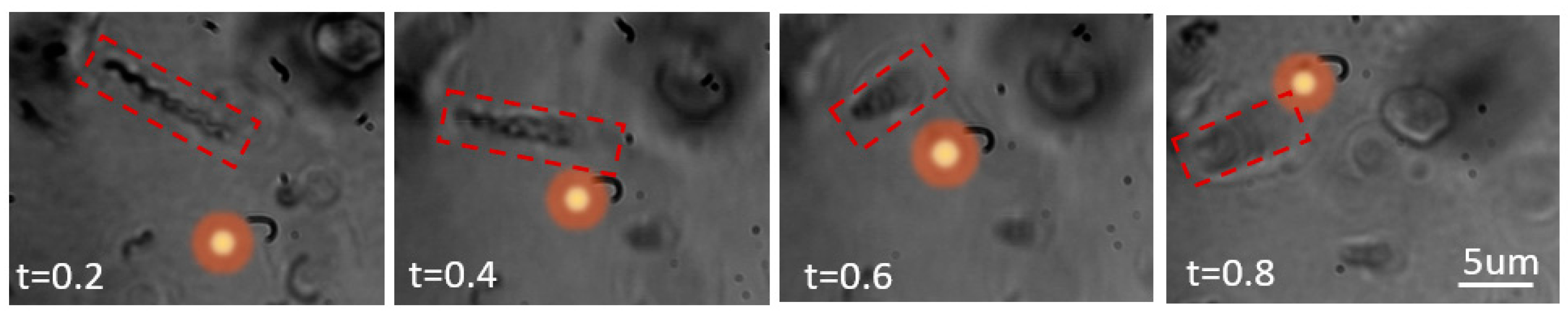
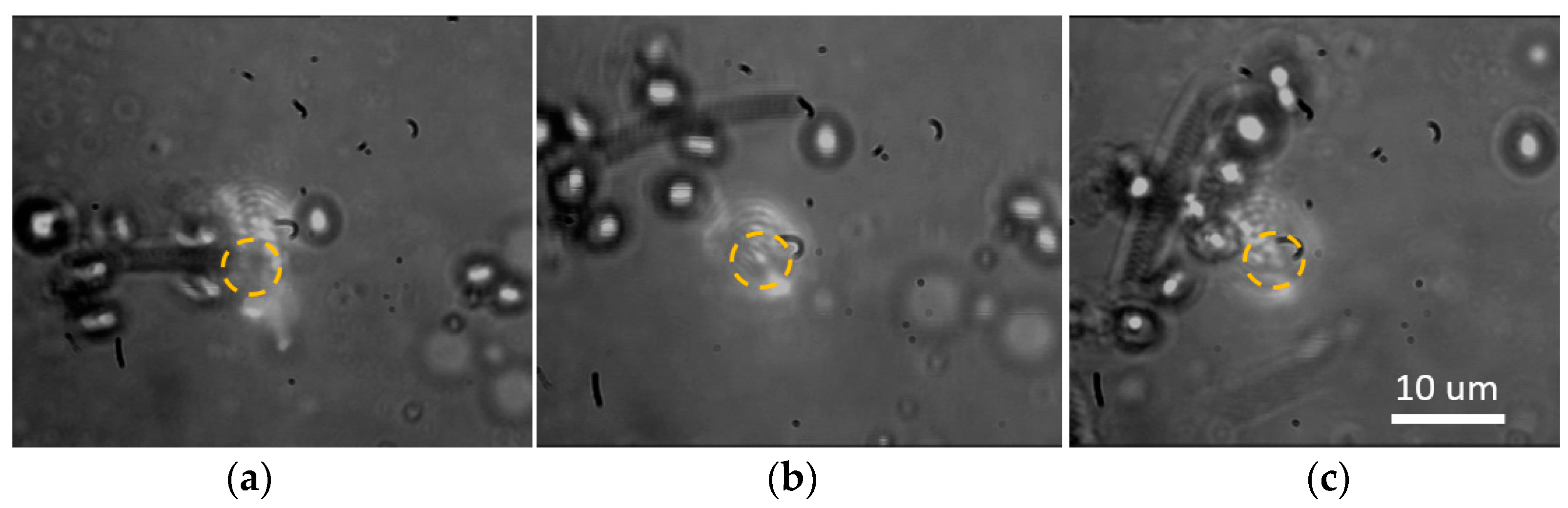
The magnitude of translational displacement can be controlled by laser power and irradiation time. However, the translation direction of the CNC microrobot in a two-dimensional space cannot be changed when fixing the position of the laser spot. To obtain a directional CNC microrobot, we use the laser beam to chase after the CNC microrobot continuously, leading to a directional change in the microrobot’s motion, as shown in Figure 7. Therefore, the CNC microrobots exhibit directional motion under optical guidance by varying the laser focus position.
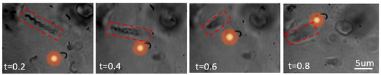
Figure 7.
Optical images of a light-guided CNC microrobot at various time intervals (laser power of 0.8 mA). The red dotted squares describe the CNC position. The yellow dots represent the laser focus position.
To verify the transportation function of CNC microrobots, the yeast cell and CNC mixed solution was prepared in a transparent sample chamber. The experiments reveal that a single CNC microrobot can load yeast cells in solution under NIR laser irradiation on the CNC body (Figure 8a). The loaded yeast cells can be transported by the CNC microrobot when the NIR laser beam is focused near the CNC (Figure 8b,c). Additionally, the number of the yeast cells loaded onto the CNC increases with an increase in laser irradiation time. Significant evidence indicates that the CNC can absorb and convert NIR energy into thermal energy [40]. The local temperature gradient is generated in the aqueous solution when the laser beam is irradiated on the CNC body, causing the yeast cells to cluster around the CNC via the thermophoresis effect [41]. Finally, the cluster cells are loaded onto the surface of the CNC microrobot due to the hydrophobicity and roughness of the CNC surface, which is beneficial to facilitate the adhesion of cells on the CNC [42,43]. Overall, CNC microrobots performing load and transport tasks for cells can be realized by NIR laser beam irradiation.
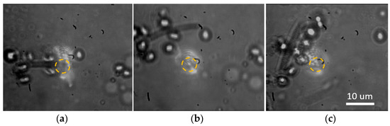
Figure 8.
(a) Optical images of a CNC microrobot loading yeast cells by laser beam irradiation on the CNC body. (b,c) Transport of yeast cells loaded by adjusting the position of laser irradiation near the CNC. Laser power is 1.07 mW. The dotted yellow areas represent the laser focus position.
4. Conclusions
We present an optically controllable and mobile microrobot using a single CNC for loading and transporting multiple yeast cells in water, which is realized by utilizing NIR laser irradiation. The results show that the CNC-based optically controlled microrobot can be driven to rotate, which is attributed to the absorption of the NIR light angular momentum, enabling the CNC microrobot to move away from irradiation point in water. Importantly, we have proposed a new motion mode of light-driven CNC microrobots whose forward direction is perpendicular to the helix axis, which is of value to adsorb contaminants in a cleaning environment due to the high aspect ratio of CNC microrobots, while the forward direction of previously reported microrobots is always in the direction of the helix axis. In addition, the translational displacement of the CNC microrobot increases with an increase in NIR irradiation time and the max translational displacement is related to the laser power. The light-induced CNC microrobot will be an effective tool for cell transporting in the biological field and for micro/nanomotors or centrifuges powering an MEMS.
Supplementary Materials
The following supporting information can be downloaded at: www.mdpi.com/xxx/s; Video S1: Optical microscopy imaging of a CNC microrobot moving in water under NIR laser beam irradiation. Figure S1: TEM image of a single CNC.
Author Contributions
Conceptualization, L.P.; methodology, Y.L. and L.P. Writing—review and editing, R.S. and Y.S.; validation, J.S.; data curation, X.W. and X.X. All authors have read and agreed to the published version of the manuscript.
Funding
This work was supported by the National Natural Science Foundation of China (Nos. 52272288, 12374355, and 51972039) and the Natural Science Foundation of Liaoning Province (No. 2023-MS-333).
Institutional Review Board Statement
Not applicable.
Informed Consent Statement
Not applicable.
Data Availability Statement
Data is contained within the article or Supplementary Material.
Acknowledgments
The authors thank the optical labs of the Dalian University of Technology.
Conflicts of Interest
The authors declare no conflicts of interest.
References
- Wang, J.; Gao, W. Nano/Microscale Motors: Biomedical Opportunities and Challenges. ACS Nano 2012, 6, 5745–5751. [Google Scholar] [CrossRef]
- Solovev, A.A.; Xi, W.; Gracias, D.H.; Harazim, S.M.; Deneke, C.; Sanchez, S.; Schmidt, O.G. Self-Propelled Nanotools. ACS Nano 2012, 6, 1751–1756. [Google Scholar] [CrossRef]
- Orozco, J.; García-Gradilla, V.; D’Agostino, M.; Gao, W.; Cortes, A.; Wang, J. Artificial Enzyme-Powered Microfish for Water-Quality Testing. ACS Nano 2013, 7, 818–824. [Google Scholar] [CrossRef]
- Guix, M.; Mayorga-Martinez, C.; Merkoci, A. Nano/Micromotors in (Bio)Chemical Science Applications. Chem. Rev. 2014, 114, 6285–6322. [Google Scholar] [CrossRef]
- Donald, B.R.; Levey, C.G.; McGray, C.D.; Paprotny, I.; Rus, D. An Untethered, Electrostatic, Globally Controllable MEMS Micro-robot. J. Microelectromech. Syst. 2006, 15, 1–15. [Google Scholar] [CrossRef]
- Bouchebout, S.; Bolopion, A.; Abrahamians, J.O.; Régnier, S. An Overview of Multiple DOF Magnetic Actuated Micro-robots. J. Micro-Nano Mechatron. 2012, 7, 97–113. [Google Scholar] [CrossRef]
- Kósa, G.; Shoham, M.; Zaaroor, M. Propulsion Method for Swimming Microrobots. IEEE Trans. Robot. 2007, 23, 137–150. [Google Scholar] [CrossRef]
- Floyd, S.R.C. Mag-Microbots: Design, Modeling, and Implementation of an Untethered Magnetically Controlled Micro-Robotic System. Ph.D. Thesis, Carnegie Mellon University, Pittsburgh, PA, USA, 2010; p. 220. [Google Scholar]
- Jing, W.; Chen, X.; Lyttle, S.; Fu, Z.; Shi, Y.; Cappelleri, D.J. A Magnetic Thin Film Microrobot with Two Operating Modes. In Proceedings of the IEEE International Conference on Robotics and Automation, Shanghai, China, 9–13 May 2011; pp. 96–101. [Google Scholar]
- Liew, L.A.; Bright, V.M.; Dunn, M.L.; Daily, J.W.; Raj, R. Development of SiCN Ceramic Thermal Actuators. In Proceedings of the IEEE International Conference on Micro Electro Mechanical Systems, Las Vegas, NV, USA, 24 January 2002; pp. 590–593. [Google Scholar]
- Palagi, S.; Mark, A.G.; Reigh, S.Y.; Melde, K.; Qiu, T.; Zeng, H.; Parmeggiani, C.; Martella, D.; Sanchez-Castillo, A.; Kapernaum, N.; et al. Structured light enables biomimetic swimming and versatile locomotion of photoresponsive soft microrobots. Nat. Mater. 2016, 15, 647. [Google Scholar] [CrossRef]
- Maggi, C.; Saglimbeni, F.; Dipalo, M.; De Angelis, F.; Di Leonardo, R. Micromotors with asymmetric shape that efficiently convert light into work by thermocapillary effects. Nat. Commun. 2015, 6, 7855. [Google Scholar] [CrossRef] [PubMed]
- Wu, Z.; Lin, X.; Wu, Y.; Si, T.; Sun, J.; He, Q. Near-Infrared Light-Triggered “On/Off” Motion of Polymer Multilayer Rockets. ACS Nano 2014, 8, 6097. [Google Scholar] [CrossRef] [PubMed]
- Dai, B.; Wang, J.; Xiong, Z.; Zhan, X.; Dai, W.; Li, C.-C.; Feng, S.-P.; Tang, J. Programmable artificial phototactic microswimmer. Nat. Nanotechnol. 2016, 11, 1087. [Google Scholar] [CrossRef] [PubMed]
- Dong, R.; Hu, Y.; Wu, Y.; Gao, W.; Ren, B.; Wang, Q.; Cai, Y. Visible-Light-Driven BiOI-Based Janus Micromotor in Pure Water. J. Am. Chem. Soc. 2017, 139, 1722. [Google Scholar] [CrossRef] [PubMed]
- Li, W.; Wu, X.; Qin, H.; Zhao, Z.; Liu, H. Light-Driven and Light-Guided Microswimmers. Adv. Funct. Mater. 2016, 26, 3164–3171. [Google Scholar] [CrossRef]
- Xuan, M.; Shao, J.; Gao, C.; Wang, W.; Dai, L.; He, Q. Self-Propelled Nanomotors for Thermomechanically Percolating Cell Membranes. Angew. Chem. Int. Ed. Engl. 2018, 57, 12463. [Google Scholar] [CrossRef] [PubMed]
- Hong, Y.; Diaz, M.; Córdova-Figueroa, U.M.; Sen, A. Light-Driven Titanium-Dioxide-Based Reversible Microfireworks and Micromotor/Micropump Systems. Adv. Funct. Mater. 2010, 20, 1568–1576. [Google Scholar] [CrossRef]
- Harder, P.; Iyisan, N.; Wang, C.; Kohler, F.; Neb, I.; Lahm, H.; Dressen, M.; Krane, M.; Dietz, H.; Oezkale, B. A Laser-Driven Microrobot for Thermal Stimulation of Single Cells. Adv. Healthc. Mater. 2023, 12, 2300904. [Google Scholar] [CrossRef] [PubMed]
- Wang, H.; Yu, J.; Lu, X.; He, X. Nanoparticle systems reduce systemic toxicity in cancer treatment. Nanomedicine 2016, 11, 103–106. [Google Scholar] [CrossRef]
- Deng, C.; Pan, L.; Ma, H.; Cui, R. Electromechanical vibrationof carbon nanocoils. Carbon 2015, 81, 758–766. [Google Scholar] [CrossRef]
- Liu, Y.; Li, C.; Zhao, M.; Shen, J.; Pan, L. A microfluidics vapor-membrane-valve generated by laser irradiation on carbon nanocoils. RSC Adv. 2023, 13, 20248–20254. [Google Scholar] [CrossRef]
- Liu, Y.; Sun, R.; Li, L.; Shen, J.; Pan, L. Carbon Nanocoil-Based Photothermal Conversion Carrier for Microbubble Transport. Coatings 2023, 13, 1392. [Google Scholar] [CrossRef]
- Jung, K.K.; Jung, Y.; Choi, C.J.; Ko, J.S. Highly reliable superhydrophobic surface with carbon nanotubes immobilized on a PDMS/adhesive multilayer. ACS Omega 2018, 3, 12956–12966. [Google Scholar] [CrossRef] [PubMed]
- Moon, H.K.; Lee, S.H.; Choi, H.C. In Vivo Near-Infrared Mediated Tumor Destruction by Photothermal Effect of Carbon Nanotubes. ACS Nano 2009, 3, 3707–3713. [Google Scholar] [CrossRef] [PubMed]
- Jagadeesh, P.; Murali, K.; Idichandy, V.G. Experimental investigation of hydrodynamic force coefficients over AUV hull form. Ocean Eng. 2009, 36, 113–118. [Google Scholar] [CrossRef]
- Panda, J.P.; Warrior, H.V. Numerical Studies on Drag Reduction of an Axisymmetric Body of Revolution with Antiturbulence Surface. J. Offshore Mech. Arct. Eng.-Trans. ASME 2021, 143, 064501. [Google Scholar] [CrossRef]
- Mehra, N.K.; Jain, K.; Jain, N.K. Pharmaceutical and biomedical applications of surface engineered carbon nanotubes. Drug Discov. Today 2015, 20, 750–759. [Google Scholar] [CrossRef]
- Das, M.; Singh, R.P.; Datir, S.R.; Jain, S. Intranuclear Drug Delivery and Effective in Vivo Cancer Therapy via Estradiol–PEGAppended Multiwalled Carbon Nanotubes. Mol. Pharm. 2013, 10, 3404–3416. [Google Scholar] [CrossRef]
- Chen, Y.; Pan, R.; Wang, Y.; Guo, P.; Liu, X.; Ji, F.; Hu, J.; Yan, X.; Wang, G.; Zhang, L.; et al. Carbon Helical Nanorobots Capable of Cell Membrane Penetration for Single Cell Targeted SERS Bio-Sensing and Photothermal Cancer Therapy. Adv. Mater. 2022, 32, 2200600. [Google Scholar] [CrossRef]
- Zhao, Y.; Wang, J.; Huang, H.; Cong, T.; Yang, S.; Chen, H.; Qin, J.; Usman, M.; Fan, Z.; Pan, L. Growth of Carbon Nanocoils by Porous a-Fe2O3/SnO2 Catalyst and Its Buckypaper for High Efficient Adsorption. Nano-Micro Lett. 2020, 12, 23. [Google Scholar] [CrossRef]
- Ashkin, A.; Dziedzic, J.M.J.; Bjorkholm, E.; Chu, S. Observation of a Single-Beam Gradient Force Optical Trap for Dielectric Particles. Opt. Lett. 1986, 11, 288–290. [Google Scholar] [CrossRef]
- Petr, K.; Sadeghpour, H.R. Laser Spinning of Nanotubes: A Path to Fast-Rotating Microdevices. Phys. Rev. 2002, 65, 161401. [Google Scholar]
- Klemens, P.G. Anharmonic Decay of Optical Phonons. Phys. Rev. 1966, 148, 845. [Google Scholar] [CrossRef]
- Usher, S.; Srivastava, G.P. Theoretical study of the anharmonic decay of nonequilibrium LO phonons in semiconductor structures. Phys. Rev. B 1994, 50, 14179. [Google Scholar] [CrossRef]
- Král, P.; Shapiro, M. Nanotube Electron Drag in Flowing Liquids. Phys. Rev. Lett. 2001, 86, 131. [Google Scholar] [CrossRef] [PubMed]
- Landau, L.D.; Lifshitz, E.M. Elasticity Theory, 3rd ed.; Pergamon Press: New York, NY, USA, 1986. [Google Scholar]
- Arnold, R.N.; Maunder, L. Gyrodynamics and Its Enginering Applications; Academic Press: New York, NY, USA, 1961. [Google Scholar]
- Whitley, S. Review of the gas centrifuge until 1962. Part I: Principles of separation physics. Rev. Mod. Phys. 1984, 56, 41. [Google Scholar] [CrossRef]
- Wang, P.; Pan, L.; Li, C.; Zheng, J. Highly Efficient Near-Infrared Photothermal Conversion of a Single Carbon Nanocoil Indicatedby Cell Ejection. J. Phys. Chem. C 2018, 122, 27696–27701. [Google Scholar] [CrossRef]
- Liu, W.; Cui, J.; Wang, J.; Xia, G.; Li, Z. Negative thermophoresis of nanoparticles in liquids. Phys. Fluids 2023, 35, 032004. [Google Scholar] [CrossRef]
- Li, D.; Yuan, L.; Yang, Y.; Deng, X.; Lü, X.; Huang, Y.; Cao, Z.; Liu, H.; Sun, X. Adsorption and adhesion of blood proteins and fibroblasts on multi-wall carbon nanotubes. Sci. China Ser. C Life Sci. 2009, 52, 479–482. [Google Scholar] [CrossRef]
- Lobo, A.O.; Antunes, E.F.; Machado, A.H.A.; Pacheco-Soares, C.; Trava-Airoldi, V.J.; Corat, E.J. Cell viability and adhesion on as grown multi-wall carbon nanotube films. Mater. Sci. Eng. C 2008, 28, 264–269. [Google Scholar] [CrossRef]


Disclaimer/Publisher’s Note: The statements, opinions and data contained in all publications are solely those of the individual author(s) and contributor(s) and not of MDPI and/or the editor(s). MDPI and/or the editor(s) disclaim responsibility for any injury to people or property resulting from any ideas, methods, instructions or products referred to in the content. |
© 2024 by the authors. Licensee MDPI, Basel, Switzerland. This article is an open access article distributed under the terms and conditions of the Creative Commons Attribution (CC BY) license (https://creativecommons.org/licenses/by/4.0/).