Article

Thick Columnar-Structured Thermal Barrier Coatings Using the Suspension Plasma Spray Process

Oerlikon Metco (US) Inc., Westbury, NY 11590, USA
*
Author to whom correspondence should be addressed.
Coatings 2024, 14(8), 996; https://doi.org/10.3390/coatings14080996
Submission received: 4 July 2024 / Revised: 31 July 2024 / Accepted: 5 August 2024 / Published: 7 August 2024
(This article belongs to the Special Issue Functional Coatings and Surface Science for Precision Engineering)

Abstract

:
Higher operating temperatures for gas turbine engines require highly durable thermal barrier coatings (TBCs) with improved insulation properties. A suspension plasma spray process (SPS) had been developed for the deposition of columnar-structured TBCs. SPS columnar TBCs are normally achieved at a short standoff distance (50.0 mm–75.0 mm), which is not practical when coating complex-shaped engine hardware since the plasma torch may collide with the components being sprayed. Therefore, it is critical to develop SPS columnar TBCs at longer standoff distances. In this work, a commercially available pressure-based suspension delivery system was used to deliver the suspension to the plasma jet, and a high-enthalpy TriplexPro-210 plasma torch was used for the SPS coating deposition. Suspension injection pressure was optimized to maximize the number of droplets injected into the hot plasma core and achieving the best particle-melting states and deposition efficiency. The highest deposition efficiency of 51% was achieved at 0.34 MPa injection pressure with a suspension flow rate of 31.0 g/min. With the optimized process parameters, 1000 μm thick columnar-structured SPS 8 wt% Y2O3-stabilized ZrO2 (8YSZ) TBCs were successfully developed at a standoff distance of 100.0 mm. The SPS TBCs have a columnar width between 100 μm and 300 μm with a porosity of ~22%. Furnace cycling tests at 1125 °C showed the SPS columnar TBCs had an average life of 1012 cycles, which is ~2.5 times that of reference air-plasma-sprayed dense vertically cracked TBCs with the same coating thickness. The superior durability of the SPS columnar TBCs can be attributed to the high-strain-tolerant microstructure. SEM cross-section characterization indicated the failure of the SPS TBCs occurred at the ceramic top coat and thermally grown oxide (TGO) interface.

1. Introduction

Thermal barrier coatings (TBCs) are widely used on both aerospace and industrial gas turbine engines to protect the hot-section superalloy components [1,2,3,4,5,6,7]. The use of TBCs (125 to 500 μm in thickness), along with internal cooling air, can reduce the metal–ceramic interface temperatures up to 200 °C [3,8]. This has enabled modern gas turbine engines to operate at gas temperatures well above the melting temperature of the superalloy, thereby improving engine efficiency and performance. Higher operating temperatures for gas turbine engines are continuously sought after in order to further improve their efficiency. As engine inlet temperatures increase, the need for reliable coatings with improved insulation properties is becoming increasingly critical for protecting the durability of superalloy components. The thermal insulation properties might be enhanced by increasing TBC thickness or reducing the TBC’s thermal conductivity. For several decades, 8 wt% Y2O3-ZrO2 (8YSZ) has been the material of choice for TBC applications due to its low thermal conductivity, high coefficient of thermal expansion, high sintering resistance, excellent toughness, and cost effectiveness [1,3,9,10].
Electron-beam physical-vapor deposition (EB-PVD) and air plasma spray (APS) are the most widely used deposition processes for the application of 8YSZ TBCs [1,2,3,5,7,8]. These two processes produce coatings with distinct microstructures and properties. The microstructure of the coating prepared by EB-PVD is composed of feather-like fine columns with gaps and porosities between columns. This unique columnar microstructure provides the coating with superior strain tolerance and thermal shock resistance. In addition, there is a minimum degree of cooling hole closure for the EB-PVD TBCs, which is a key benefit of the EB-PVD process [2]. However, the EB-PVD process is expensive and is used primarily in the most severe applications, such as blades and vanes in aircraft engines. In contrast, the APS TBCs contain a laminar splat microstructure with extensive microstructural defects such as microcracks, large splat boundaries, and pores, which all contribute to low thermal conductivity. Due to their laminar porous microstructure and lack of in-plane mechanical compliance during thermal cycling, APS TBCs are generally less durable compared to EB-PVD TBCs. The APS process has been widely used for TBC deposition on combustor liners, shrouds, and most power generation components due to its lower cost and requirement for thicker coatings.
Efforts for developing strain-tolerant TBCs using the low-cost APS process have been carried out in the past decades. A variation of the APS process developed is called the dense vertically cracked (DVC) TBC coating process [4,7,11,12,13,14,15,16]. In this process, hot plasma spray conditions and fine powders are normally required for generating well-molten particles and coatings with high tensile stresses to initiate the formation of vertical cracks. The vertical cracks provide strain tolerance and serve a similar function as intercolumnar gaps in the EB-PVD coatings at a much lower cost. Due to the dense microstructure, the thermal conductivity of DVC TBCs is higher than that of conventional APS porous TBCs [7].
Compared to EB-PVD vapor deposition, the powders used in the APS process are large and cause the closure of the cooling holes in the engine parts [17,18]. Therefore, masking the large number of cooling holes before coating deposition is necessary, which is a tedious and time-consuming process [17,18]. Recently, a suspension plasma spray (SPS) process has been developed for the deposition of coatings with unique properties [19,20,21,22,23]. In SPS, submicron particles are dispersed in a solvent such as water or ethanol to form a suspension, and then, the suspension is injected into the plasma torch. Depending on the process parameters, vertically cracked or columnar TBCs can be produced using the SPS process [24]. It has been demonstrated that the fine particles used in the SPS process make it promising for minimizing the degree of closure of the cooling holes and thus avoiding the application of the masking [21]. Numerous studies have been carried out on the SPS deposition of thermal barrier coatings. VanEvery et al. investigated the formation mechanism of columnar structure SPS YSZ TBCs [23]. The columns are formed when the powder droplets are deposited on the sides of surface humps present on the substrates. This process occurs when the droplets are small enough to be affected by the plasma flow. Thus, the columnar structures tend to be readily observed in SPS coatings sprayed with sub-micrometer or nanometer-sized powders. Joeris et al. evaluated the major factors influencing the formation of columnar TBCs in axial suspension plasma spraying processes [24]. Bernard et al. investigated the effects of SPS columnar microstructures and bond coat surface preparation on TBC properties [25]. Multilayer SPS Gd2Zr2O7/YSZ TBCs were also prepared by Mahade et al. [26]. In most of the reported work on SPS TBC deposition, short standoff distances (50.0 mm–75.0 mm) were widely used due to the limitations of plasma gun capabilities. Short standoff distances for coating complex-shaped engine components with curves will not be practical since the plasma torch may collide with the component during spraying. Therefore, there is a need to develop SPS columnar TBCs at longer standoff distances.
In our previous work, it has been demonstrated that DVC TBCs can be produced at long standoff distances using the high-enthalpy and cascaded TriplexPro-210 plasma torch thanks to its stable and well-defined arc behavior that results in extremely uniform powder heating [15]. TriplexPro 8YSZ DVC coatings with a vertical crack density of ~2.3 cracks/mm were successfully made at standoff distances of 125 mm using Metco 204F powder feedstock [15]. The unique process capability of the high-enthalpy Triplex-210 torch with a long and stable plasma jet makes it an ideal option for SPS TBC deposition at long standoff distances. In this work, the suspension plasma spray process for producing thick and columnar thermal barrier coatings using the TriplexPro-210 plasma torch was developed. The SPS coating deposition behavior and coating thermal cycling durability were investigated and compared with the reference APS DVC TBCs.

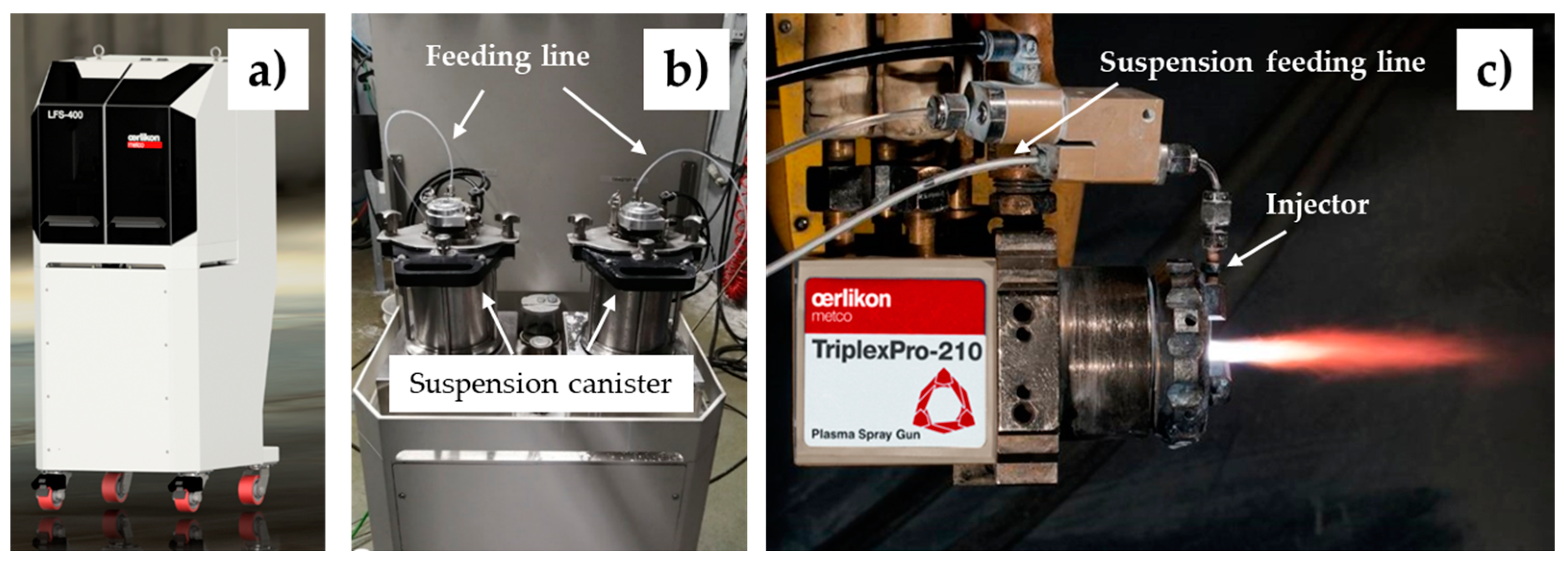
2. Experimental Procedures

An ethanol-based suspension containing 25.0 wt% submicron 8YSZ (Metco 6608) was used in this study. A pressure based Metco LSF 400 feeder equipped with two suspension canisters was used to deliver the suspension to the plasma jet (Figure 1). The coatings were sprayed using the TriplexPro-210 plasma gun with a 9 mm nozzle. Ar and He were used as the primary and secondary plasma gases, respectively. Ar was also used as the suspension carrier gas. A series of experiments on the suspension injection pressure, which varied from 0.14 MPa to 0.48 MPa, were carried out in order to optimize the droplet/particle trajectory in the plasma jet. The coating deposition efficiency was measured based on the ratio of coating weight to the weight of the total dry feedstock delivered. With optimized suspension injection pressure, a fixed-scan experiment across a substrate was also performed to understand the splat formation behavior. A SPS 8YSZ coating with a thickness of ~1000 μm was deposited onto a 5 mm thick Hastelloy substrate (JC Machines & Manufacturing corporation, Santa Ana, CA) with a ~150.0 μm thick APS NiCoCrAlYHfSi (Amdry 386-4) bond coat (Ra = 7.5 μm) for thermal cycling durability evaluation. The detailed TBC information is listed in Table 1. The column density was calculated by dividing the number of columns with the cross-section length. In order to compare the durability of SPS TBCs to that of APS DVC TBCs, ~1000 μm APS DVC TBCs with a vertical crack density of ~2.5 cracks/mm were also prepared on the same A386-4 bond-coated substrates as SPS TBCs. The detailed microstructure and properties for the reference APS DVC TBCs can be found in our previous publication [14].
A furnace cycling test (FCT) was performed for the evaluation of coating durability. In the FCT test, a CMTM rapid temperature furnace (CM Furnaces Inc. Bloomfield, NJ, USA) was used. The thermal cycle consisted of a 10 min heat-up from room temperature to 1125 °C, a 40 min hold at 1125 °C, and a 10 min forced air quench. A total of three TBC samples were cycled for each of the SPS TBC and APS DVC TBC systems. The coating was considered to be in failure when spallation was observed.
For cross-sectional microstructure characterization, the coatings were cut along the cross-section using a diamond saw with a slow speed to minimize damage. The cut samples were then cold-mounted with epoxy, followed by grinding and polishing. The grinding and polishing were carried out using an automatic Struers Tegramin-25 grinder–polisher system (Struers, Champigny-sur-Marne, France). The cross-sectional microstructures and surface topography were examined via scanning electron microscopy in backscattered electron (BSE) modes (Hitachi S-3400N, Hitachi America, Ltd., Santa Clara, CA, USA). The coating porosity was evaluated via image analyses of the cross-sections of as-sprayed coatings.

3. Results and Discussion

3.1. Optimization of Suspension Injection and Deposition Efficiency

The Metco LSF 400 feeder used in the suspension plasma spray process is a pressure-based liquid delivery system. The injection pressure controls, to a large extent, the droplet/particle trajectory in the plasma jet. Under inappropriate injection pressure, the liquid stream will under-penetrate or over-penetrate the hot core of the plasma jet. To maximize the amount of droplets/particles injected into the hot plasma core and achieve the best particle-melting states and deposition efficiency, the injection pressure must be optimized. In the experiment, the injection pressure was changed from 0.14 MPa to 0.48 MPa while other parameters such as plasma power, plasma gas flow, standoff distance, etc., were kept constant. The injection pressure was considered to be optimized when the highest coating deposition efficiency was obtained. The effect of injection pressure on the coating deposition efficiency is shown in Figure 2. With the increase in injection pressure from 0.14 MPa to 0.34 MPa, the coating deposition efficiency gradually increased from 29% to 51% and then decreased to 41% at 0.48 MPa. The highest deposition efficiency of 51% was achieved at 0.34 MPa injection pressure with a suspension flow rate of 31.0 g/min.

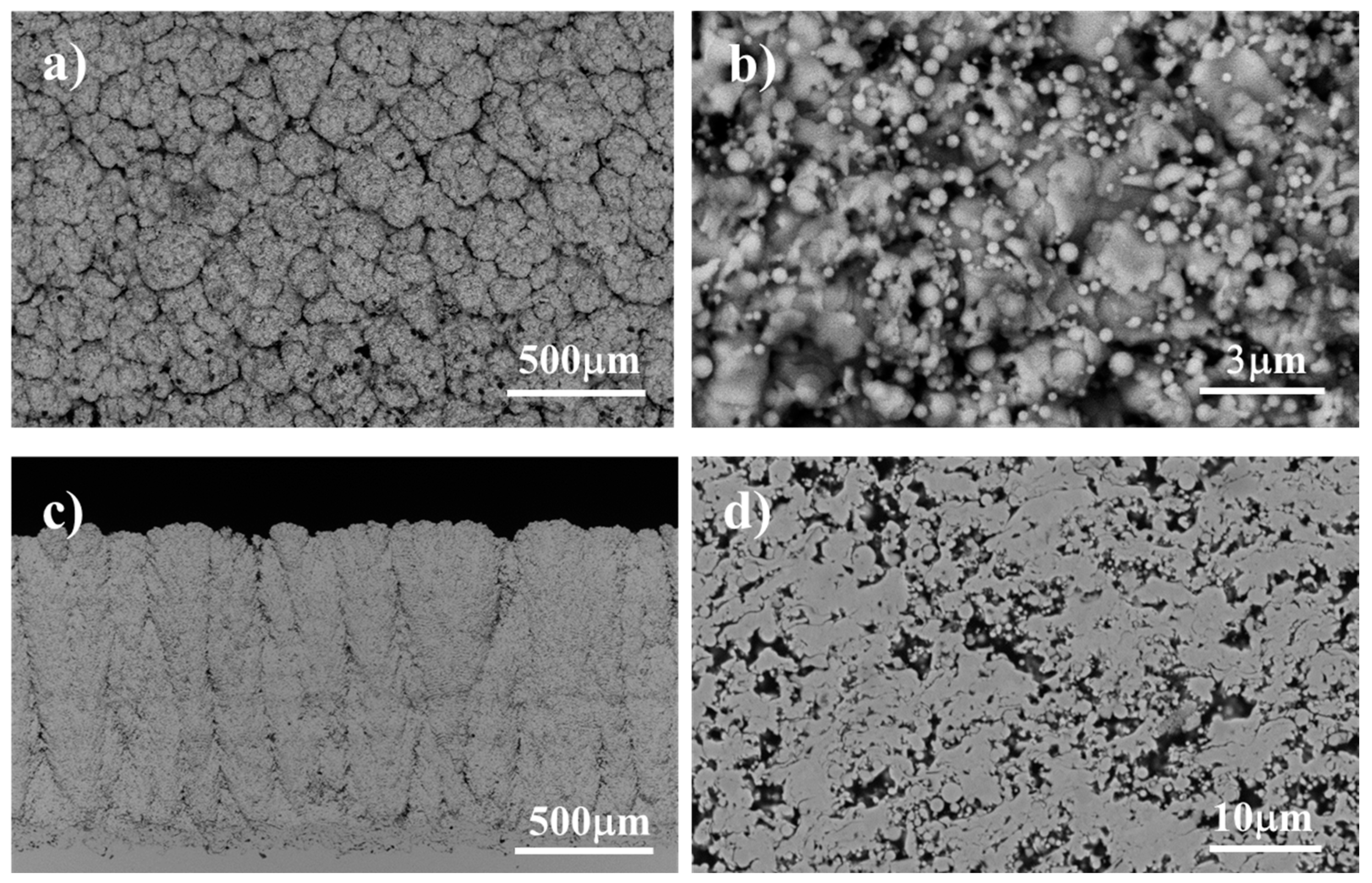
3.2. Morphologies of SPS Deposits

To identify the morphologies of deposits traveling in different zones of the plasma jet, a fixed-scan experiment was carried out. In the fixed-scan experiment, the plasma jet is scanned across the substrate under the optimized suspension injection pressure (0.34 MPa) at a standoff distance of 100.0 mm. The coating deposition pattern on the substrate is shown in Figure 3. The scan pattern can be divided into three areas: a dark band in the scan center with a bandwidth of ~10.0 mm, white bands with width of ~4.0 mm distributed on each side of the dark band, and powdery deposits at the band edge. SEM microstructure characterization indicated the edge of the deposition pattern is mainly composed of spheres with diameters less than 1.0 μm (Figure 3a). The center of the dark deposition band is mainly composed of well-molten and solidified splats (Figure 3b). The splats’ average diameter ranges from 0.5 μm to 6.0 μm. The white deposit is a mixture of ultrafine splats and submicron spheres (Figure 3c). These microstructural differences indicated the various droplet/particle trajectories in the plasma jet. The splat morphology observed in the dark band indicated the suspension droplets traveled along the hot region of the plasma jet and experienced solvent evaporation, melting, and formation of splats upon impact onto the substrate, while the powdery spheres at the edge of the deposit band indicated the suspension droplets traveled along the edge of the plasma jet (cooler region) and experienced solvent evaporation, melting, rapid cooling, and re-solidifying processes. They deposited on the substrate as powdery solid spheres.
The SPS process has been intensively investigated in the past two decades. It has been widely recognized that a short standoff distance in the SPS process is normally required to form a coating with good adherence to the substrate [23,25,27,28,29]. The higher surface area of the finer particles used in the SPS process makes them heat up quickly and cool down at a much faster rate than the larger particles used in the conventional powder thermal spray process. With the increased distance from the torch, fine particles re-solidify quickly before hitting the substrate and form a porous coating microstructure with poor adhesion to the substrate. Therefore, short standoff distances are widely reported for high-quality SPS coating deposition. The short standoff distance in the SPS process is a big drawback for coating deposition on complex-shaped engine parts since the plasma torch may collide with the component during spraying. One way to improve the standoff distance in the SPS process is to keep the particles in a melting state before hitting the substrate. This can be realized by using a high power, high-enthalpy, and stable plasma torch such as the TriplexPro-210 used in the current work. The TriplexPro-210 torch creates a much longer plasma jet compared to conventional torches such as 9MB, F4, and SG-100. The longer plasma jet prevents the cooling and re-solidification of the in-flight particles before hitting the substrate at longer standoff distances. As observed in the fixed-scan experiment, the center band of the deposit is composed of well-molten splats, while the band edge is composed of mixed splats and re-solidified spheres. The large area of splat formation in the fixed-scan experiment clearly demonstrated the capability of the cascaded TriplexPro torch to keep most of the in-flight fine particles in a molten state before hitting the substrate at a longer standoff distance.

3.3. Coating Microstructure

The SPS 8YSZ coating microstructures are shown in Figure 4. Surface microstructure characterization showed a cauliflower-like structure (Figure 4a). High magnification shows the coating is mainly composed of ultrafine splats and some spherical particles (Figure 4b), which are very similar to those observed in the fixed-scan experiment. The polished coating cross-section showed a columnar microstructure with a column density of ~4.1 columns/mm. The columnar width ranges between 100 μm and 300 μm. The total coating thickness is ~1000 μm. High magnification showed the coating is porous with a porosity ~22%. Some fine spherical particles embedded in the dense splat area were also observed.
The columnar formation mechanism of SPS TBCs had been studied by VanEvery et al. [23]. The plasma drag forces during substrate impingement dominate the droplet inertia and redirect the droplet velocity from normal to along the substrate surface. Consequently, droplets impact preferentially on asperities, generating deposits that grow to become columnar structures. This process occurs when the droplets are small enough to be affected by the plasma flow. The effect of process conditions on SPS columnar formation has been widely studied [24,30,31,32]. One key factor affecting columnar formation is the roughness of the bond coat. Depending on bond coat surface roughness, coatings with various column densities can be achieved. The column density decreases gradually with the increase in bond coat roughness [30]. SPS TBCs with columnar density over 10 columns/mm were achieved on the mirror-polished and low-roughness bond coat surface [30,32,33]. In our experiment, the column density is lower compared to the literature reported SPS TBCs. The major reason can be attributed to the higher bond coat roughness used in this study (Ra = 7.5 μm). Increasing the roughness will reduce the number of relevant asperities and therefore result in low column density.

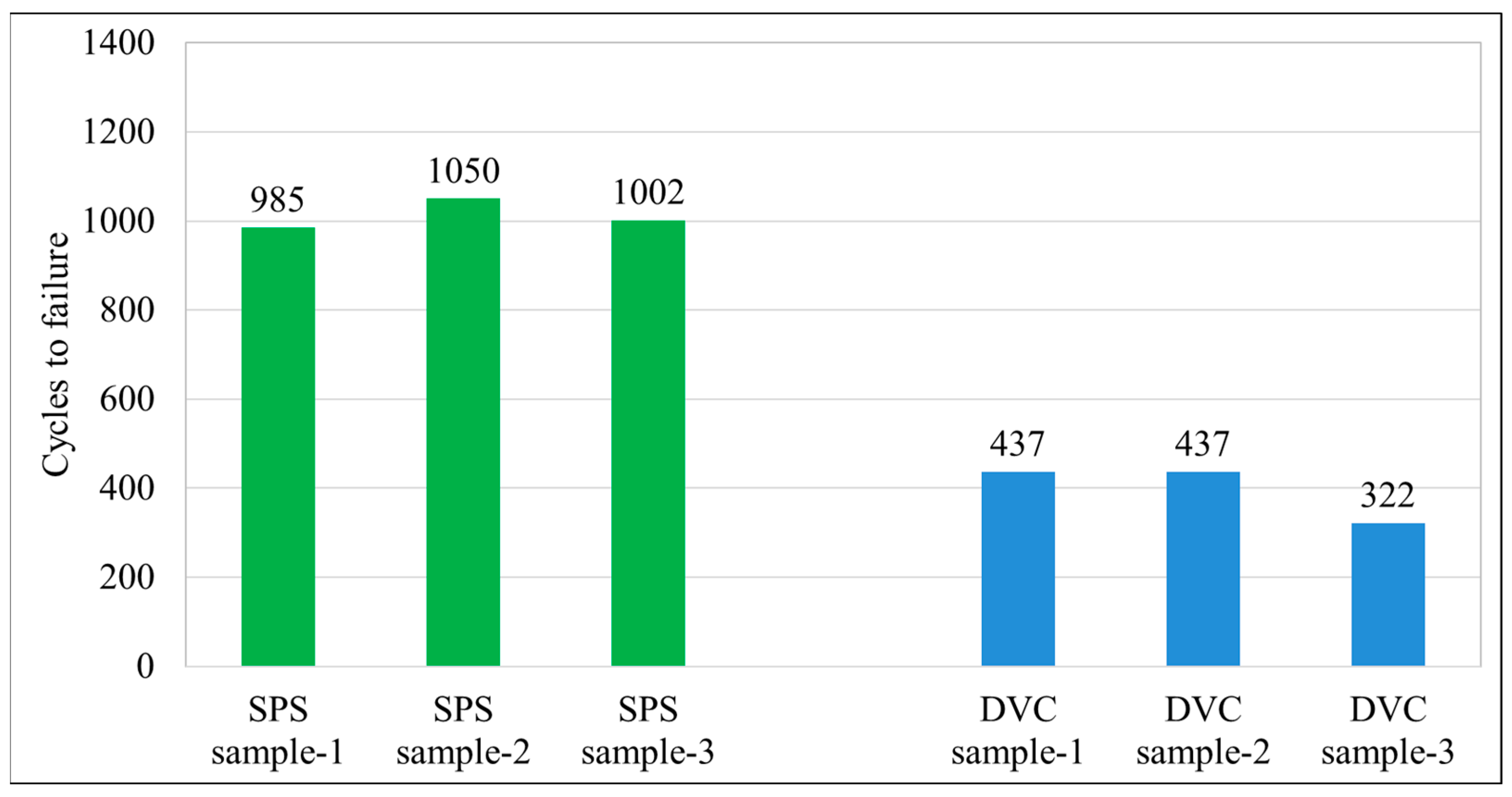
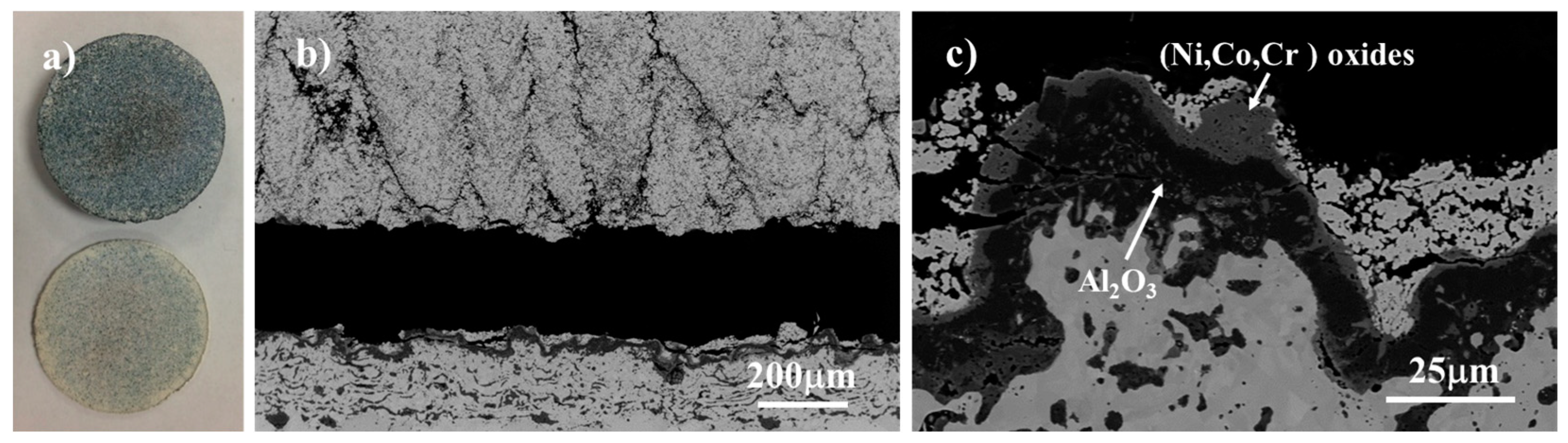
3.4. Furnace Cycle Behavior
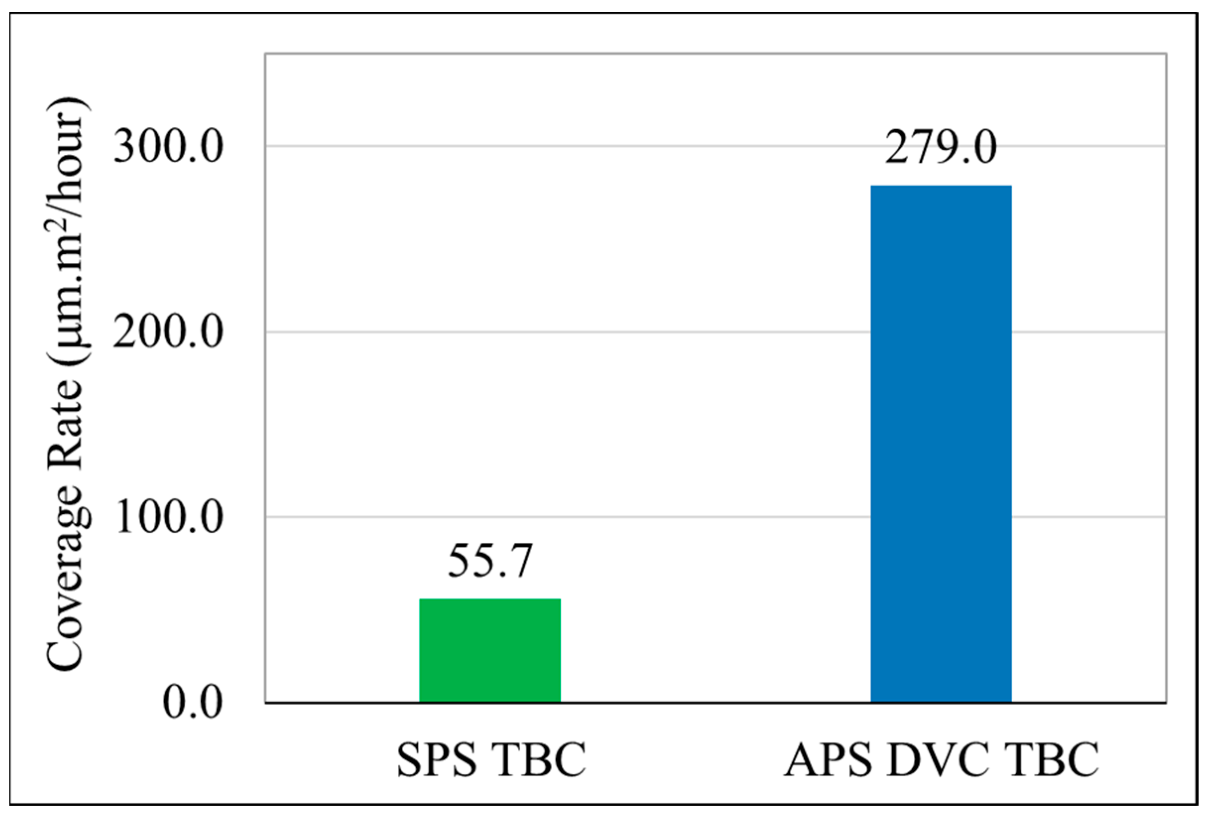
The thermal cycling durability of the SPS columnar TBCs was evaluated at 1125 °C. In order to compare the durability of SPS TBCs to that of APS DVC TBCs, three APS DVC TBCs with a vertical crack density of ~2.5 cracks/mm were also cycled together with the SPS TBCs on the same A386-4 bond-coated substrates. Both the APS DVC TBCs and the SPS columnar TBCs were cycled to failure, and the cyclic life for each sample is plotted in Figure 5. The lifetime of the SPS TBC ranged from 985 to 1050 cycles, with an average life of 1012 cycles, while the APS DVC TBCs cyclic life ranged from 322 to 437 cycles, with an average life of 399 cycles. The average cyclic lives of SPS columnar TBCs are more than 2.5 times those of APS DVC TBCs. The superior durability of the SPS TBCs can be attributed to the higher-strain-tolerant microstructure. The unmelted particles, the porosity, and the columnar microstructures all impart strain tolerance to SPS TBCs.
Photograph and SEM microstructures of the FCT failed SPS TBCs are shown in Figure 6. The SPS TBCs failed by delamination of the entire ceramic top coat as one piece from the substrate. Cross-sectional SEM micrographs show the failure occurs at the YSZ/TGO interface (Figure 6b), which is similar to the failure mode of APS DVC TBCs [14,15]. Cracks between columns were observed, which could be attributed to the sintering effect of columns after long-term exposure in the thermal cycling test. High magnification views show the oxidation of bond coats with an average TGO thickness of ~16.5 ± 5.7 μm (Figure 6c). The TGO layer is mainly composed of Al2O3; however, (Ni, Cr, Co)-rich oxides were also observed within the TGO layer, which is the result of the depletion of Al in the bond coat.

3.5. Coverage Rate

Coverage rate is a measurement which evaluates the coating volume deposition rate. The unit used in this work is expressed as μm·m2/h, meaning the deposited coating thickness (μm) on a given area (m2) per hour. It was calculated based on the coating thickness achieved on a certain area in a given coating time. The coverage rate of SPS is 55.7 μm·m2/h, while APS DVC has a coverage rate of 279.0 μm·m2/h (Figure 7). The SPS TBC coverage rate is about 5 times slower than the APS process. The low coverage rate of SPS TBCs is mainly due to the lower powder feeding rate. In the SPS process, 25.0 wt% 8YSZ suspension was used with a suspension feeding rate of 31.0 g/min, which is equal to a 7.75 g/min solid 8YSZ powder feeding rate (31.0 g/min × 25.0 wt% = 7.75 g/min), while in APS DVC deposition, a 40.0 g/min powder feeding rate was used. To make the SPS process more economical, future research should focus on improving the SPS coating coverage rate, such as by improving deposition efficiency and/or suspension solid concentration, etc.

4. Conclusions

Thick columnar-structured 8YSZ TBCs were developed using the suspension plasma spray process at a standoff distance of 100.0 mm. Suspension injection pressure has a significant effect on coating deposition efficiency. The highest deposition efficiency of 51% was achieved at 0.34 MPa injection pressure with a suspension flow rate of 31.0 g/min. SPS TBCs with columnar width between 100 and 300 μm and porosity of ~22% were deposited using the optimized injection pressure. The average furnace cycling life of the SPS columnar TBCs was 1012 cycles, which is ~2.5 times that of reference air-plasma-sprayed dense vertically cracked TBCs applied with the same coating thickness. The superior durability of the SPS TBCs can be attributed to the high-strain-tolerant microstructure. The embedded spherical particles, the porosity, and the columnar microstructures all impart strain tolerance to SPS TBCs. Due to the relatively lower solid powder feeding rate, the coverage rate of SPS TBC is about 5 times slower than the typical APS DVC TBC deposition. Improving the SPS coating coverage rate should be the focus of future SPS research.

Author Contributions

D.C.: conceptualization, methodology, validation, formal analysis, investigation, and writing—original draft preparation. C.D.: investigation, resources, and writing—review and editing. All authors have read and agreed to the published version of the manuscript.

Funding

This research received no external funding.

Institutional Review Board Statement

Not applicable.

Informed Consent Statement

Not applicable.

Data Availability Statement

Data are contained within the article.

Conflicts of Interest

Authors Dianying Chen, Christopher Dambra were employed by the company Oerlikon Metco (US) Inc. The remaining authors declare that the research was conducted in the absence of any commercial or financial relationships that could be construed as a potential conflict of interest.

References

  1. Clarke, D.R.; Oechsner, M.; Padture, N.P. Thermal-barrier coatings for more efficient gas-turbine engines. MRS Bull. 2012, 37, 891–898. [Google Scholar] [CrossRef]
  2. Darolia, R. Thermal barrier coatings technology: Critical review, progress update, remaining challenges and prospects. Int. Mater. Rev. 2013, 58, 315–348. [Google Scholar] [CrossRef]
  3. Padture, N.P.; Gell, M.; Jordan, E.H. Thermal Barrier Coatings for Gas-Turbine Engine Applications. Science 2002, 296, 280–284. [Google Scholar] [CrossRef] [PubMed]
  4. Hardwicke, C.U.; Lau, Y.C. Advances in Thermal Spray Coatings for Gas Turbines and Energy Generation: A Review. J. Therm. Spray Technol. 2013, 22, 564–576. [Google Scholar] [CrossRef]
  5. Miller, R.A. Thermal Barrier Coatings for Aircraft Engines: History and Directions. J. Therm. Spray Technol. 1997, 6, 35–42. [Google Scholar] [CrossRef]
  6. Bose, S.; DeMasi-Marcin, J. Thermal barrier coating experience in gas turbine engines at Pratt & Whitney. J. Therm. Spray Technol. 1997, 1997, 99–104. [Google Scholar]
  7. Feuerstein, A.; Knapp, J.; Taylor, T.; Ashary, A.; Bolcavage, A.; Hitchman, N. Technical and Economical Aspects of Current Thermal Barrier Coating Systems for Gas Turbine Engines by Thermal Spray and EBPVD: A Review. J. Therm. Spray Technol. 2008, 17, 199–213. [Google Scholar] [CrossRef]
  8. Meier, S.M.; Gupta, D.K. The Evolution of Thermal Barrier Coatings in Gas Turbine Engine Applications. J. Eng. Gas Turbines Power 1994, 116, 250–257. [Google Scholar] [CrossRef]
  9. Vaßen, R.; Bakan, E.; Mack, D.E.; Guillon, O. A Perspective on Thermally Sprayed Thermal Barrier Coatings: Current Status and Trends. J. Therm. Spray Technol. 2022, 31, 685–698. [Google Scholar] [CrossRef]
  10. Smialek, J.L.; Miller, R.A. Revisiting the Birth of 7YSZ Thermal Barrier Coatings: Stephan Stecura. Coatings 2018, 8, 255. [Google Scholar] [CrossRef]
  11. Taylor, T.A. Thermal Barrier Coating for Substrates and Process for Producing It. U.S. Patent 5073433, 17 December 1991. [Google Scholar]
  12. Guo, H.; Kuroda, S.; Murakami, H. Segmented thermal barrier coatings produced by atmospheric plasma spraying hollow powders. Thin Solid Films 2006, 506–507, 136–139. [Google Scholar] [CrossRef]
  13. Chen, D.; Rocchio-Heller, R.; Dambra, C. Segmented Thermal Barrier Coatings for ID and OD Components Using the SinplexPro Plasma Torch. J. Therm. Spray Technol. 2019, 28, 1664–1673. [Google Scholar] [CrossRef]
  14. Chen, D.; Dambra, C.; Dorfman, M. Process and properties of dense and porous vertically-cracked yttria stabilized zirconia thermal barrier coatings. Surf. Coatings Technol. 2020, 404, 126467. [Google Scholar] [CrossRef]
  15. Chen, D.; Dambra, C.; Dorfman, M. Deposition, Microstructure and Thermal Cycling Performance of Strain-Tolerant Thermal Barrier Coatings. J. Therm. Spray Technol. 2023, 32, 1108–1114. [Google Scholar] [CrossRef]
  16. Karger, M.; Vaßen, R.; Stöver, D. Atmospheric plasma sprayed thermal barrier coatings with high segmentation crack densities: Spraying process, microstructure and thermal cycling behavior. Surf. Coat. Technol. 2011, 206, 16–23. [Google Scholar] [CrossRef]
  17. Beeck, A.; Bögli, A.; Fernihough, J. Process of Plugging Cooling Holes of a Gas Turbine Component. EP1076107A1, 14 February 2001. [Google Scholar]
  18. Fernihough, J.; Boegli, A.; Stankowski, A. Process of Masking Cooling Holes of a Gas Turbine Component. U.S. Patent 20050215686A1, 29 September 2005. [Google Scholar]
  19. Kassner, H.; Siegert, R.; Hathiramani, D.; Vassen, R.; Stoever, D. Application of Suspension Plasma Spraying (SPS) for Manufacture of Ceramic Coatings. J. Therm. Spray Technol. 2008, 17, 115–123. [Google Scholar] [CrossRef]
  20. Vaßen, R.; Kaßner, H.; Mauer, G.; Stöver, D. Suspension Plasma Spraying: Process Characteristics and Applications. J. Therm. Spray Technol. 2010, 19, 219–225. [Google Scholar] [CrossRef]
  21. Tang, Z.; Kim, H.; Yaroslavski, I.; Masindo, G.; Celler, Z.; Ellsworth, D. Novel Thermal Barrier Coatings produced by Axial Suspension Plasma Spray. In Proceedings of the International Thermal Spray Conference & Exposition, Hamburg, Germany, 27–29 September 2011; pp. 571–575. [Google Scholar]
  22. Cotler, E.M.; Chen, D.; Molz, R.J. Pressure-Based Liquid Feed System for Suspension Plasma Spray Coatings. J. Therm. Spray Technol. 2011, 20, 967–973. [Google Scholar] [CrossRef]
  23. VanEvery, K.; Krane, M.; Trice, R.; Wang, H.; Porter, W.; Besser, M.; Sordelet, D.; Ilavsky, J.; Almer, J. Column Formation in Suspension Plasma-Sprayed Coatings and Resultant Thermal Properties. J. Therm. Spray Technol. 2011, 20, 817–828. [Google Scholar] [CrossRef]
  24. Joeris, J.; Tiwari, A.; Brinckmann, S.; Kurze, F.; Guillon, O.; Vaßen, R. Evaluation of major factors influencing the TBC topcoat formation in axial suspension plasma spraying (SPS). Int. J. Appl. Ceram. Technol. 2023, 20, 884–895. [Google Scholar] [CrossRef]
  25. Bernard, B.; Quet, A.; Bianchi, L.; Schick, V.; Joulia, A.; Malié, A.; Rémy, B. Effect of Suspension Plasma-Sprayed YSZ Columnar Microstructure and Bond Coat Surface Preparation on Thermal Barrier Coating Properties. J. Therm. Spray Technol. 2017, 26, 1025–1037. [Google Scholar] [CrossRef]
  26. Mahade, S.; Curry, N.; Björklund, S.; Markocsan, N.; Nylén, P. Thermal conductivity and thermal cyclic fatigue of multilayered Gd2Zr2O7/YSZ thermal barrier coatings processed by suspension plasma spray. Surf. Coat. Technol. 2015, 283, 329–336. [Google Scholar] [CrossRef]
  27. Fauchais, P.; Vardelle, M.; Vardelle, A.; Goutier, S. What Do We Know, What are the Current Limitations of Suspension Plasma Spraying? J. Therm. Spray Technol. 2015, 24, 1120–1129. [Google Scholar] [CrossRef]
  28. VanEvery, K.; Krane, M.J.M.; Trice, R.W. Parametric study of suspension plasma spray processing parameters on coating microstructures manufactured from nanoscale yttria-stabilized zirconia. Surf. Coat. Technol. 2012, 206, 2464–2473. [Google Scholar] [CrossRef]
  29. Delbos, C.; Fazilleau, J.; Rat, V.; Coudert, J.F.; Pateyron, B. Phenomena Involved in Suspension Plasma Spraying Part 2: Zirconia Particle Treatment and Coating Formation. Plasma Chem. Plasma Process. 2006, 26, 393–414. [Google Scholar] [CrossRef]
  30. Zhou, D.; Guillon, O.; Vaßen, R. Development of YSZ Thermal Barrier Coatings Using Axial Suspension Plasma Spraying. Coatings 2017, 7, 120. [Google Scholar] [CrossRef]
  31. Ganvir, A.; Joshi, S.; Markocsan, N.; Vassen, R. Tailoring columnar microstructure of axial suspension plasma sprayed TBCs for superior thermal shock performance. Mater. Des. 2018, 144, 192–208. [Google Scholar] [CrossRef]
  32. Bellippady, M.; Florent, M.; Björklund, S.; Li, X.H.; Robert, F.; Kjellman, B.; Joshi, S.; Markocsan, N. Characteristics and performance of suspension plasma sprayed thermal barrier coatings on additively manufactured superalloy substrates. Surf. Coat. Technol. 2023, 472, 129926. [Google Scholar] [CrossRef]
  33. Gupta, M.; Li, X.-H.; Peng, R.; Ottosson, A.; Gillberg, P.; Girgulis, J. Understanding the effect of bondcoat surface treatment on enhanced lifetime of suspension plasma sprayed thermal barrier coatings. Surf. Coatings Technol. 2024, 482, 130716. [Google Scholar] [CrossRef]
Figure 1. Photos of LSF-400 suspension feeding system (a,b) and TriplexPro-210 suspension plasma spray (c).
Coatings 14 00996 g001
Figure 2. Effect of injection pressure on the coating deposition efficiency.
Coatings 14 00996 g002
Figure 3. Typical microstructures of deposits from the fixed-scan experiment: (a) powdery deposits at the band edge; (b) dark deposits at the band center; (c) white deposits at the intermediate band edge.
Coatings 14 00996 g003
Figure 4. Top views and cross-sections of SPS 8YSZ coatings at low and high magnifications. (a,b) surface morphologies; (c,d) cross-sections.
Coatings 14 00996 g004
Figure 5. Thermal cycle life of SPS TBCs and APS DVC TBCs.
Coatings 14 00996 g005
Figure 6. Photo (a) and SEM microstructures (b,c) of failed SPS TBCs after 1002 cycles.
Coatings 14 00996 g006
Figure 7. Coating coverage rate of SPS TBCs and APS DVC TBCs.
Coatings 14 00996 g007
Table 1. TBC specimen information.
LayerComposition (%)Thickness
Top Coat8 wt%Y2O3-stabilized ZrO2~1000 μm
Amdry 386-4 Bond CoatCo: 22, Cr: 17, Al:12, Hf: 0.5, Y:0.5, Si: 0.4, Ni: balance~150.0 μm
Hastelloy X SubstrateCr:22.24, Fe: 18.09, Mo: 8.55, Co: 1.46, W: 0.62, Mn: 0.46, Si: 0.31, Cu: 0.11, Ti: 0.020, Ni: balance~5.0 mm
Disclaimer/Publisher’s Note: The statements, opinions and data contained in all publications are solely those of the individual author(s) and contributor(s) and not of MDPI and/or the editor(s). MDPI and/or the editor(s) disclaim responsibility for any injury to people or property resulting from any ideas, methods, instructions or products referred to in the content.

