Article

Future Parabolic Trough Collector Absorber Coating Development and Service Lifetime Estimation

National Institute of Chemistry, Hajdrihova 19, 1000 Ljubljana, Slovenia
*
Author to whom correspondence should be addressed.
Coatings 2024, 14(9), 1111; https://doi.org/10.3390/coatings14091111
Submission received: 19 July 2024 / Revised: 1 August 2024 / Accepted: 14 August 2024 / Published: 2 September 2024
(This article belongs to the Special Issue Coatings for Advanced Devices)

Abstract

:
This work presents a study on the optical and mechanical degradation of parabolic trough collector absorber coatings produced through the spray coating application technique of in-house developed paint. The main aim of this investigation is to prepare, cure, load, and analyze the absorber coating on the substrate under conditions that mimic the on-field thermal properties. This research incorporates predicted isothermal and cyclic loads for parabolic trough systems as stresses. Biweekly inspections of loaded, identical samples monitored the degradation process. We further used the cascade of data from optical, oxide-thickening, crack length, and pull-off force measurements in mathematical modelling to predict the service life of the parabolic trough collector. The results collected and used in modelling suggested that cyclic load in combination with iso-thermal load is responsible for coating fatigue, influencing the solar absorber optical values and resulting in lower energy transformation efficiency. Finally, easy-to-apply coatings made out of spinel-structured black pigment and durable binder could serve as a low-cost absorber coating replacement for a new generation of parabolic trough collectors, making it possible to harvest solar energy to provide medium-temperature heat to decarbonize future food, tobacco, and paint production industrial processes.

1. Introduction

Globally, heat represents around 74 percent of the energy used by the industrial sector and contributes to over 20 percent of the total global energy consumption across all sectors [1]. Currently, the majority of industrial heat generation is derived from the process of burning fossil fuels. The most energy-intensive industrial processes, such as cement, iron and steel, and glass production, require high temperatures (>1000 °C) of industrial heat. These processes are extremely difficult to decarbonize [2]. A quite similar amount of final energy consumption to iron and steel production is present in the food, tobacco, and paper industries, but the industrial heat temperature here is much lower. In the food and tobacco industry, the majority (55%) of the industrial heat is below 100 °C and 45% is between 100 and 400 °C [3]. Decarbonization in all sectors is essential and urgent [4]. Using solar thermal energy can significantly reduce energy costs and carbon dioxide emissions for a wide range of industrial product processing applications. In the EU, the cumulated surfaces of solar thermal in operation in the European Union in 2022 are evaluated at 58.8 million m2. In 2022, the EU concentrated solar power (CSP) capacity was assessed at 2333 MW [5]. CSP systems use parabolic trough collectors (PTCs) and linear Fresnel reflectors (LFRs) or tower technology to provide heating and cooling to manufacturing facilities. Different technologies, i.e., high-temperature heat pumps and heat storage, are combined to form a single system that can reliably provide the necessary heat for a wide variety of manufacturing processes, including those in the textile, plastics, wood, metal, and chemical industries [6].
Solar absorber coating is a crucial part of the absorber as it serves as an energy entry point, tailoring energy conversion efficiency [7]. From the perspective of the initial energy harvesting point and after a certain period of time on the field, energy transformation efficiency is important to maximize the absorber output. To maximize the absorber output, different coating types were developed in the past [8]. Coating complexity and the coating application process is consequently related to the coating’s final price. Electroplating and physical vapour deposition (PVD) offer high figure of merit [9] but also higher production price. For mass production on flat surfaces, coil-coating application is suitable [10]. For pipes that are used in CSP PVD production, it is an established practice that needs high vacuum [11,12]. Thickness-sensitive spectrally selective coatings made by spray application could meet the demands of CSP [13,14]. Furthermore, the absorber coating must have high solar absorptance and low thermal emittance at the CSP operating temperature, so its initial properties and durability are critical [15,16]. Every day, the collectorcoating system experiences a wide range of temperatures and solar concentration fluctuations caused by day and night exchange and cloud passage, resulting in cycling from field to maximum temperature. If the coating or the substrate is not stable enough, optimal energy transformation efficiency will fail. A decrease in energy transformation efficiency as an increase in thermal emittance and decrease in solar absorptance result from the coating deteriorating under the effects of thermal load, oxygen influence, and environmental conditions (such as dew and humidity if the absorber pipe is not in a vacuum). Coating degradation could result in optical or mechanical failure as a result of accelerated ageing that simulates the on-field situation. Estimating the lifetime of an absorber coating has historically made use of a number of different approaches. Accelerated ageing was performed through extensive thermal cycling [17], isothermally aged in air [18,19], under real high solar flux [20] and thermal cycling [15,21,22]. Research often solely focuses on studying fatigue materials and their consequences. Rarely, extensive research is conducted that includes service-life predictions. A procedure for accelerated life testing of flat plate solar absorber surfaces was developed within the framework of the Materials in Solar Thermal Collectors working group of the International Energy AgencySolar Heating and Cooling Programme [23,24]. Out of Task X, a European standard (EN 12975-3-1 [25]) and international standards (ISO 22975-3:2014 [26]) were made. In our opinion, such an approach for PTC absorber coatings and tower coatings is delicate, as in Task X for the estimation of activation energy, where they used much higher temperatures than the operation temperature. This is not a problem when you are testing vented flat plate solar absorber coatings for collectors working under conditions corresponding to those in a typical solar domestic hot water system or combi system. In the aforementioned case, a higher temperature than the stagnation temperature used in accelerated testing does not cause fatigue to the substrate (copper or aluminium). The oxidation of the polished surface beneath the coating, which accounts for the increase in thermal emittance value, is negligible. The fact that aluminium thickness stops at a few nm in air at temperatures around 100 °C supports that statement [27]. In the case of parabolic trough collectors, the operation temperature is much higher in contrast to a vented flat plate collector as a result of the higher concentration of solar energy on the small surface. Consequently, operation temperature is often already limiting material use at high pressure, and the additional step towards higher temperature needed for achieving the acceleration factor is not acceptable. Nevertheless, the findings of this study broaden the range of the model put forward in our previous research [15] in the direction of parabolic trough collectors. The objective of this study was to establish the protocol that determines the lifetime of scalable parabolic trough collector coatings made by, i.e., electrodeposition, deep coating, and spray coating applications. The coatings undertook laboratory testing to simulate the loads that could be experienced on-field, demonstrating their fatigue behaviour while maintaining excellent optical characteristics. The theoretical model integrated both mechanical and optical degradation by using variables such as solar absorptance, thermal emittance, oxide thickness, and fracture evaluation values to accurately predict the service lifetime of the coating. We present a laboratory-based degradation evaluation through visual/infrared and X-ray diffraction (XRD) spectroscopy, scanning electron microscopy (SEM), and energy-dispersive X-ray spectroscopy (EDS). Our investigation concentrates on assessing the timeline of energy transformation efficiency decline for industrial coatings. We analyse both initial and loaded coatings to provide comprehensive data. The approach given here can be utilised to evaluate coatings utilised for competitive solar heat feeding in future Solar Heat Industrial Processes (SHIPs). We show degradation information from a lab point of view using X-ray diffraction (XRD) spectroscopy, scanning electron microscopy (SEM), and energy-dispersive X-ray spectroscopy (EDS) on both the initial and loaded coatings. This helps us figure out how long it takes for industrial coatings to lose their ability to efficiently transform solar energy into useful heat. Coatings used for competitive solar heat feeding the future industrial processes using solar heat can be evaluated using the approach provided here. It is important to emphasise that in order to obtain an accurate result, we must assess the entire system, including the coating and substrate.

2. Materials and Methods

2.1. Coating Preparation
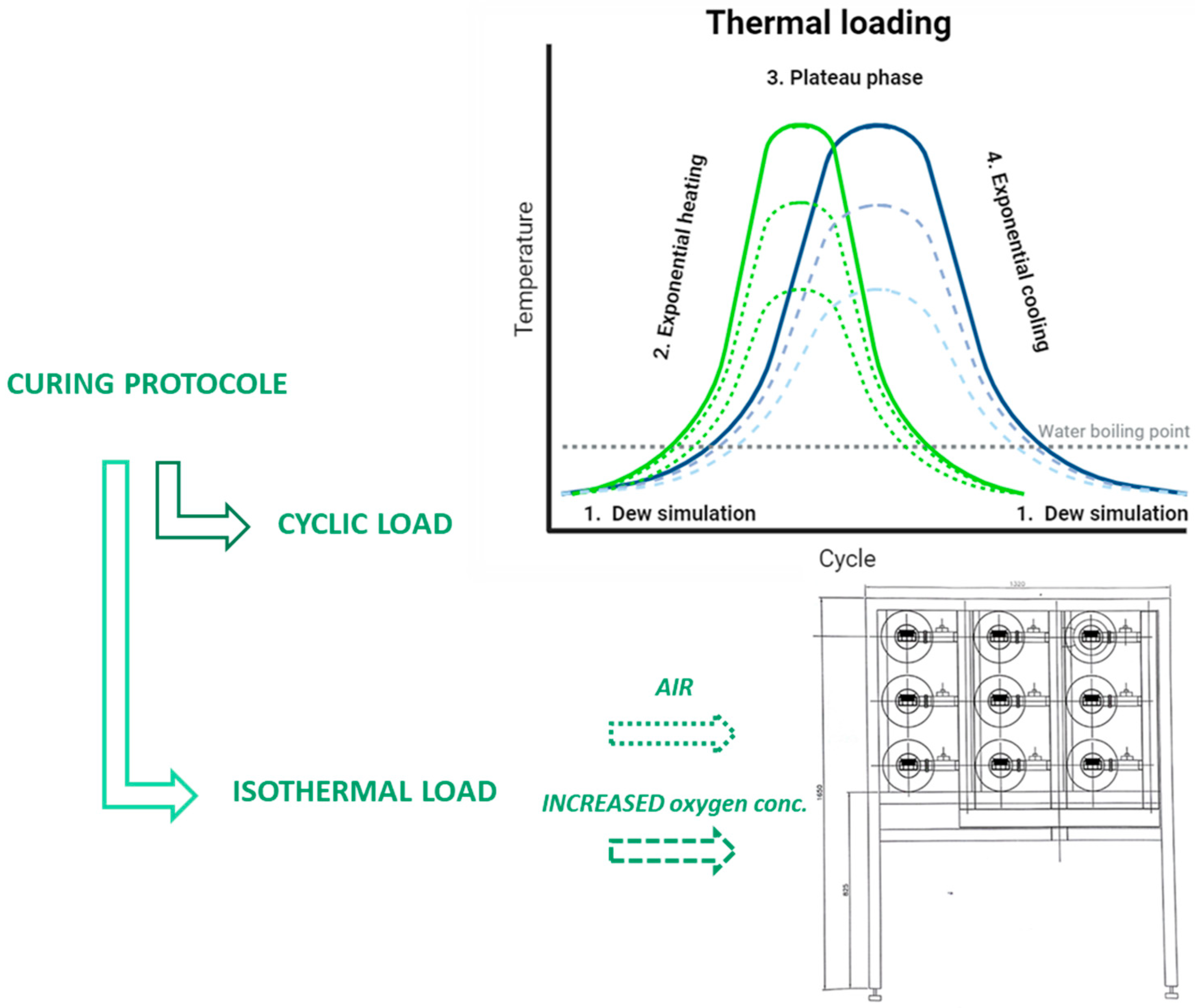
We added the pigment (Black 444, Shepherd Colour Company, West Chester Township, OH, USA) to a suitable amount of resin (Dowsil 2405, Dow, Torrance, CA, USA), a solvent (xylene, Fluka), and additives. We then stirred the mixture with the dissolver VMA Dispermat CN10 for 30 min at 1200 rpm. Furthermore, we milled the pigment dispersions in a Dyno-mill Research Laboratory agitator bead mill (WAB, Willy A. Bachofen AG Maschinenfabrik, Muttenz, Switzerland) using 0.3 mm diameter zirconia beads for half an hour at 5000 rpm. We diluted the nanoparticle pigment dispersion to the appropriate viscosity after milling and then prepared it for the spray coating. Coupons made out of steel 5 × 5 cm in size were polished by grid paper (1000). After spray application, wet coating thickness was 40 microns. Coatings were cured in an air oven according to established protocol [16].

2.2. Coating Load

Using a series of computer-controlled furnaces equipped with humidity/dew generators and increased oxygen concentration settings, we simulated the thermal load normally faced by solar loop absorbers supplying industrial heat in a lab setting. Following the coating curing protocol, Figure 1 schematically presents the loading protocol for identical samples of PTC absorber coatings. We performed iso-thermal loading at 300, 400, and 500 °C. We exposed the samples in parallel to a cyclic load consisting of four steps. The first step involved simulating dew and purging the furnace with steam. After 5 min of dew simulation at room temperature, exponential heating takes place, followed by a short plateau phase (300, 400, and 500 °C) and exponential cooling to room temperature. Heating and cooling temperature was set to 6, 8, and 10 °C/min. In addition to air atmosphere in furnaces, in one example oxygen was added to the furnace.

2.3. Characterization

We assessed weekly surface crack propagation using optical microscopy, evaluated the weekly growth of the oxide layer beneath the coating using metallurgical cross-cut evaluation and a Zeiss UltraPlus (Jena, Germany) analytical low-voltage scanning electron microscope (SEM), estimated adhesion using pull-off testing, and gained a comprehensive understanding of the collector material, the growth of the oxide layer below, and the diffusion processes inside the collector surface using EDS. To obtain X-ray powder diffraction (XRD) patterns, an X-ray powder diffractometer (PANalytical X’Pert PRO, Malvern, UK) with CuKα radiation (λ = 1.5406 Å) was used. The 2θ angle was set between 10° and 70°, and the scanning speed was 0.04°/s. A Lambda 950 UV/VIS spectrometer was used to measure the near normal spectral reflectance of the samples at wavelengths from 250 nm to 2500 nm. We used a Bruker Vertex 70v spectrometer (Billerica, MA, USA) with gold-coated integrating sphere equipment to measure the samples’ normal hemispherical directional reflectance spectra in the infrared range, which covers wavelengths from 1.5 to 16.5 m. We obtained the values for solar absorptance (αS; Equation (1)) and thermal emittance (εT; Equation (2)) from the measured reflectance spectra calculated numerically from the measured reflectance spectra at room temperature using the equations below:
α S = 0.25   μ m 2.5   μ m I s λ ( 1 R ( λ ) ) d λ 0.25   μ m 2.5   μ m I s ( λ ) d λ
ε T = 1.5   μ m 16.5   μ m I b λ ( 1 R ( λ ) ) d λ 1.5   μ m 16.5   μ m I b ( λ ) d λ
where Is(λ) is the reference solar spectral irradiance of AM 1.5 according to the ISO standard (ISO 9845-1, 1992 [28]), R(λ) is the spectral reflectance, and Ib (λ) is the blackbody radiation at 80 °C.

2.4. Mathematical Modelling

In order to obtain a quantitative description of the degradation of the PTC absorber coatings, we use a mathematical model which we proposed in our previous study (15), which is designed to explicitly take into account the isothermal- and thermal-cycling loads to which the absorber coating is exposed during its operation. The model distinguishes between the thermal cycles performed in the dry and humid atmosphere. It is assumed in the model that the optical degradation processes in the PTC absorber coating can be described by the first-order kinetic equation:
d α d t = k T ,   T f ( α )
where α is the extent of the conversion of the observed quantity (i.e., absorptance), f(α) is the relevant reaction model and k(TT) is the rate constant, which depends on the temperature (T) during the isothermal load (it) and the magnitude of the temperature difference ΔT during dry (dc) or wet/humid (wc) thermal cycling. Here, the degradation due to the isothermal load is given as a function of time, while the thermal cycling is given as a function of the number of cycles (n). For the model evaluation, it should be known in advance how many thermal cycles of each type (dry/wet) are expected during a given time interval. As the loads are not present simultaneously, we can write to a good approximation a cumulative rate of the degradation as a sum of individual contributions:
d α d t = d α d t i t + τ d c d α d n d c + τ w c d α d n w c
Each term is supposed to have its own specific form. In particular, the isothermal rate constant is assumed to be of the Arrhenius type [24], and the cycling rate constant is assumed to have a power-law dependence on the temperature change, ΔT, according to the Coffin–Manson relationship [29], which is commonly applied in modelling the fatigue failure of materials subjected to thermal cycling. The factors τdc/wc = dn/dt are added in order to keep explicit time dependence in the equation.
The individual reaction models fi(α) (i = {1 = it, 2 = dc, 3 = wc}) differ from each other, as well as model parameters Ai, e0, and βi, which are determined in the separate sets of experiments dealing exclusively with one type of the degradation load. Fitting procedures are used for deriving individual parameters.
d α d t i t = k 1 T f 1 α = A 1 e x p e 0 T f 1 α
d α d t d c = k 2 Δ T f 2 α = A 2 e x p e 0 T β 2 f 2 α
d α d t w c = k 3 Δ T f 3 α = A 3 e x p e 0 T β 3 f 3 α

3. Results

3.1. Crack Evolution

Crack evolution can affect the coating’s optical properties by trapping part of the solar energy inside the cracks, thereby increasing the absorptance if cracks and pores are on a proper micro to nano level [30]. Conversely, if the cracks are too large, the substrate will affect the absorptance values, leading to decreased absorptance. We evaluated the cracks in our samples on identical location every two weeks, using an optical microscope and cured them before beginning testing. After each measurement, we processed the images with custom-developed software to estimate the length and thickness of any cracks present in the coating. We should highlight that in the case of PTC coatings made by spray-out of pigment dispersion prepared as described above and loaded at temperatures 300, 400, and 500 °C after proper curing, we did not observe the paint shrinkage that resulted in cracks on the majority of samples if we applied proper coating thickness. Figure 2 represent examples at 300 °C, where the coating thickness limits the optimal thickness. During the first heat-exposure flux, the formation of minor cracks was detected on the surface of the coating as a result of the difference in the thermal expansion of the substrate, the binder decomposition and shrinkage, the formation of the oxide layer, and the coating densification. The appearance of cracks was only spotted in two of our samples, but we did not notice growth as a function of loading time.
On other samples, we did not discover cracks as the samples were stable enough at the tested temperature.

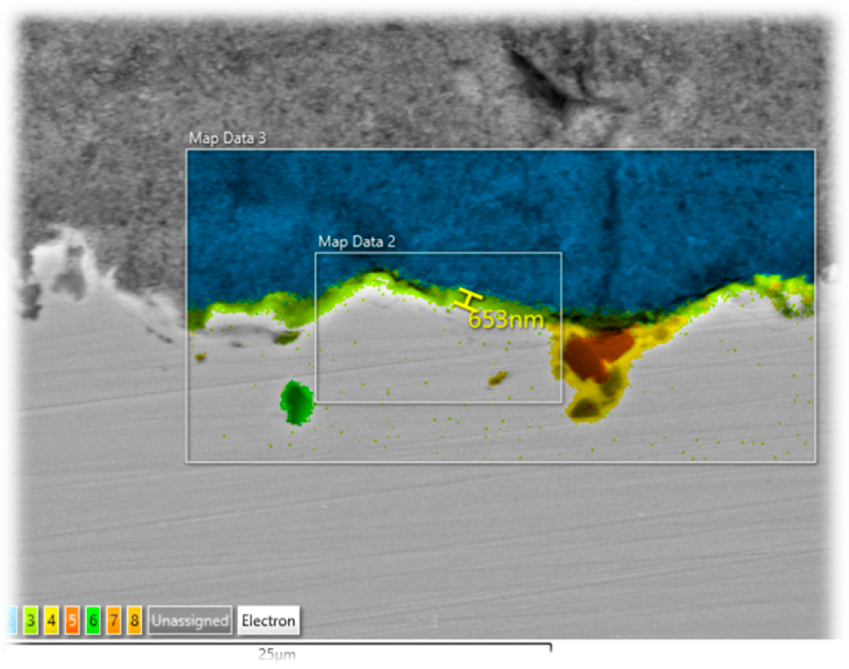
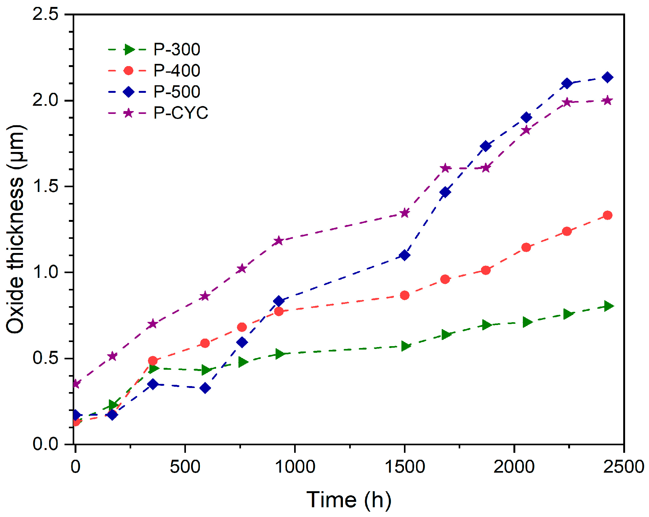
3.2. Oxide Thickness Evaluation

We used metallurgical cross-cutting, along with SEM microscopy, to study and understand the interface between the substrate and coating. According to Figure 3, the coating changes with load and stress. The picture shows how the oxide protective layer connects to the coating layer that forms on the substrate surface. Moreover, oxide thickness is estimated on 653 nm after 591 h of iso-thermal load at 400 °C.
The growth of the oxide layer during thermal loading is significantly slower at lower temperatures, whereas it grows more quickly at higher temperatures (Figure 4). In the case of cyclic thermal loading, the formation of the oxide layer was similar to that detected at high temperatures since the cyclic loading also involved exposure to 500 °C in the plateau phase. Furthermore, it is also evident that exposure to a lower (300 and 400 °C) load temperature causes significantly slower oxide thickness growth. Despite over 2000 h at these temperatures, the oxide thickness stays below 1 micron, suggesting that the dense oxide layer does not limit or weaken adhesion, even after prolonged accelerated stress.

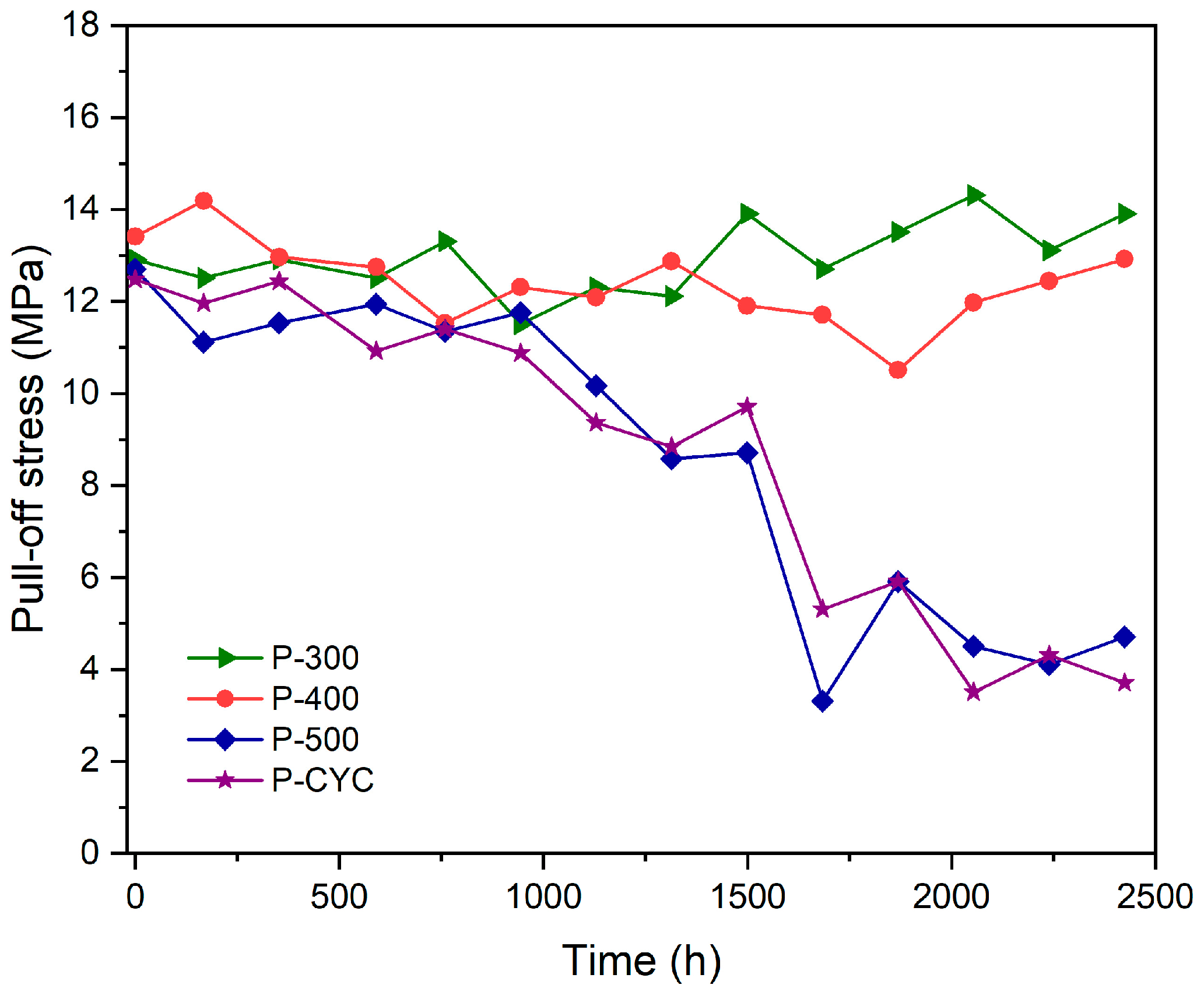
3.3. Adhesion Evaluation

The oxygen ion diffusion distance and load temperature directly influence the growth rate of thermally grown oxide on the substrate. The spray-deposited absorber coatings are a consequence of solvent-borne paint being porous after curing, so oxygen has limited access to the substrate surface. If the oxide layer’s non-uniform thickness is too high, it may change the local stress state and cause the absorber coating to crack. As a result of crack evolution and oxide growth, coatings can de-bond after a thermal load. The coating layer peeling off from the substrate or cracking within a coating layer can lead to the failure of the entire optical coating system. The latter is more prevalent at temperatures above 750 °C [31]. To evaluate the mechanical failure in the coating, we studied adhesion strength as a function of time during thermal load exposure. We measured the release behaviour using a standard pull-off test, which assesses the adhesive properties by measuring the stress required to pull away the dolly from a flat, rigid, cylindrical punch initially pressed into contact with the adhesive surface. Our tests provided a time evolution of the average critical pull-off stress for different loads. By inspecting the punch surface, we identified different delamination layers. Figure 5 represents the dolly surface after the pull-off test at the different temperatures. When epoxy glue adheres the dolly to the loaded paint surface, it delaminates at its weakest point. If the adhesion is good, the weakest point will be the glue, which appears as a white dolly surface. When paint decomposes or lacks sufficient binder, it becomes the weakest point, and its black pigment composition results in a black dolly surface. Furthermore, if thick oxide grows below the surface, delamination occurs over the oxide layer. In the last scenario, the dolly surface should be grey. As shown in Figure 5, the most common colours on dolly surfaces are white and black. This indicates excellent paint adhesion with some delamination. That is why additional inspections are necessary if delamination takes place in the paint layer. Most often, we witness delamination with a very thin layer. As the surface is very rough, we remove only the top layer.
Furthermore, we measured the force needed to remove the glued dolly from the substrate. Figure 6 presents the results, demonstrating the stable force required to remove the dolly over time for samples loaded at 300 and 400 °C. The pull-off test’s value for dolly debonding was initially around 13 MPa and displayed rather steady behaviour, with a slightly increasing trend over time. For samples loaded under cyclic load or at 500 °C at the beginning, for the first 1000 h, the pull-off force remains constant, but after 1000 h of load, it looks like the oxide thickness reaches a limiting thickness and the pull-off force decreases with time [15]. After this period, we noticed a discrepancy in adhesion force for samples at higher temperatures. Different modes of delamination can explain the variation in the pull-off stress values, as illustrated in Figure 5.

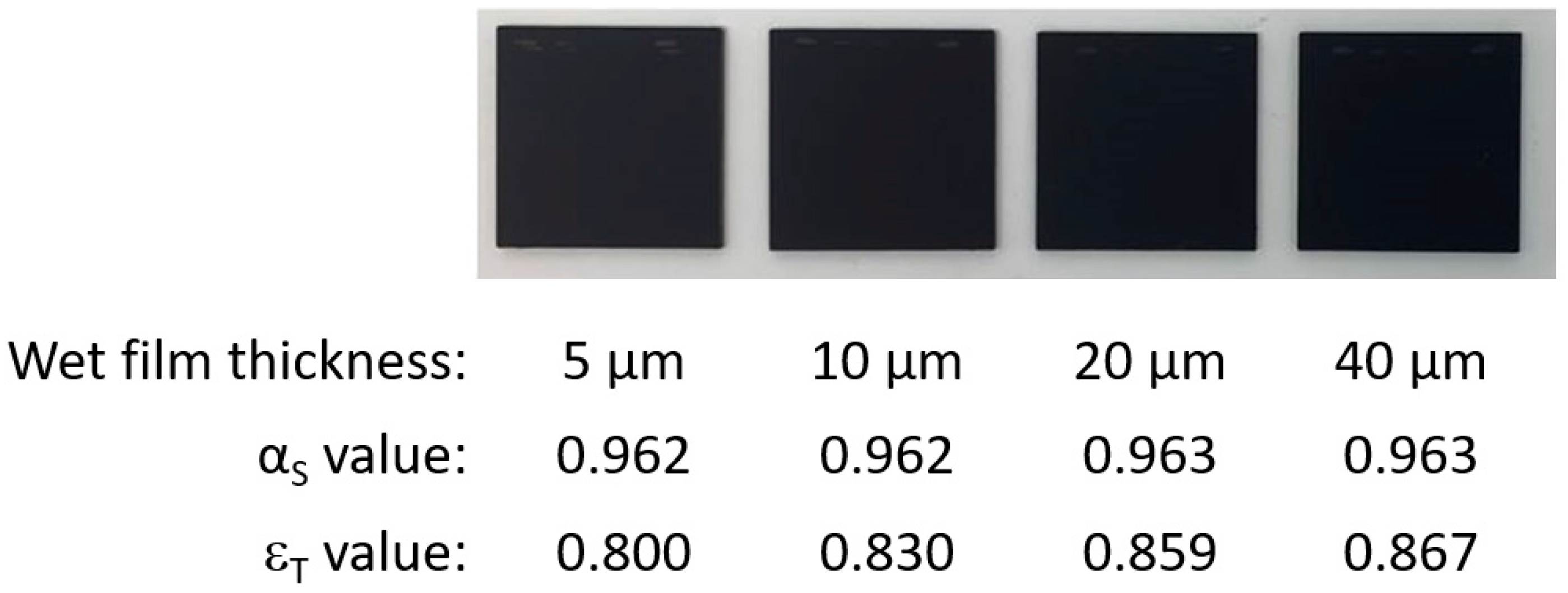
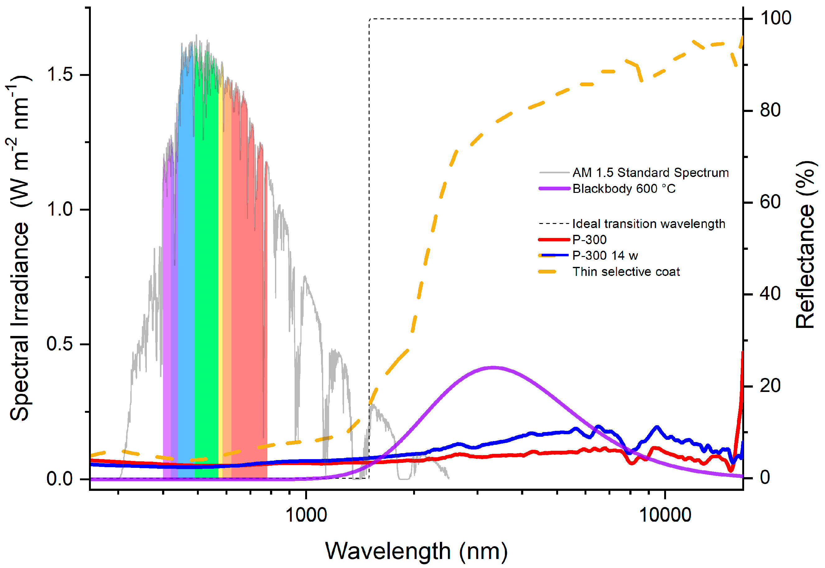
3.4. Coating Optical Property Changes Due to Thermal Load

In general, with some exceptions, researchers develop, classify, and select absorber coatings based solely on their peak thermal performance, disregarding factors such as cost, durability, and operating conditions. In our opinion, durability and cost are crucial when we are talking about mass production. The optical properties have a direct impact on the levelized energy cost. As a result, it is necessary to measure the spectral absorptance and thermal emittance of new and stressed coatings. A perfect spectrally selective absorber has almost no reflectance at short wavelengths and a lot of reflectance at long wavelengths. The operating temperature determines the sharp change between these two regimes (Figure 7). However, the overall properties across the solar spectral range are significant, as thermal emittance must also be considered, particularly for spectrally selective coatings. Substrate polish and the mirror-like structure are impacted by thermal emittance. Applying coatings to a sand-blasted surface results in a thermal emittance of approximately 80%. Furthermore, decreasing coating thickness directly affects thermal emittance because the IR penetration range is limited. We should keep in mind that too low a thickness means non-maximal solar absorptance; therefore, there is always a trade-off. For the coating used in our experiments, we measured a very high absorptance (>0.96), but not low emittance, because they are non-selective. Also, we discovered that the absorptance does not depend on the thickness (Figure 8). We prepared wet 5, 10, 20 and 40 µm thick coatings and measured absorption and emittance. As you can see from the figure, we achieved similar absorptance of 96% plus, but unfortunately, we have an emittance over 80% if the substrate is not polished.
To achieve lower emittance, a coating with around 1.5 µm thickness needs to be prepared on a polished substrate. Figure 8 represents the reflection spectra for the visual and IR ranges. In orange, a thin selective coating is presented on the surface of a polished substrate. That shape is similar to that of the dashed line, indicating an almost ideal selective coating. A delta εTT of 60% relates to the difference in spectra between P-300 and thin selective coatings.
Furthermore, every two weeks, we measured how solar absorptance changed with isothermal and cyclic thermal loads. Figure 9 displays that we achieved more than 96% solar absorptance for our samples. We also discovered that the coatings showed different degradation at different temperatures, but we want to emphasize that after 2500 h, the developed coatings’ solar absorptance did not drop below the threshold value. A slight increase in solar absorptance is seen at the beginning, and later values drop between 1000 and 1500 h of thermal load. In our opinion, this shift is related to measurement error and averaging the sample values as the deviation is in the range of 0.5%. These observations are consistent with the variation in their solar absorptance during ageing. Note that the upper and lower error bar values indicate the maximum and minimum measured solar absorptance values from the batch of samples aged under the same conditions. If we performed proper curing, the solar absorptance of our coatings remained relatively stable. However, absorptance continued decreasing only if the loading temperature was above 700 °C (not part of the article).

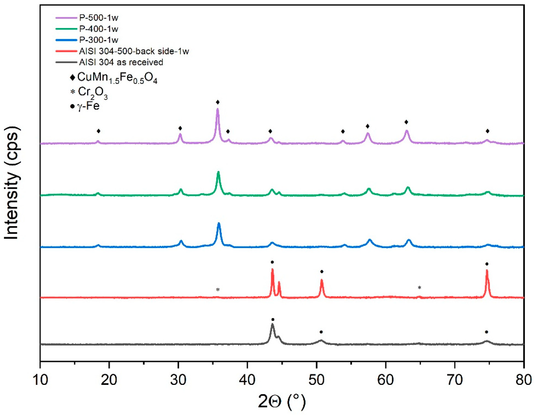
3.5. XRD Spectroscopy Evaluation

We used X-ray diffraction (XRD) to look at the crystal structure of the pigment and the oxide growth of the substrate-protecting layer to find the weakest spot in the solar absorber’s coating. XRD diffractograms of the initial substrate and coated samples (Figure 10) after one week of isothermal testing at 300, 400, and 500 °C in an air furnace are presented. Examining the substrates reveals that a thin oxide layer is present after one week of exposure to 500 °C. We observed the martensitic and austenitic phases in untreated specimens. A mechanical polishing effect is associated with the martensitic presence. The thermal load intensifies the emphasis on austenitic phases. Over time, we also note the formation of Cr2O3 [32]. Spinel pigment is very stable and does not show any change in crystal structure at temperatures up to 500 °C. At higher temperatures, we witness changes related to diffusion [16].

3.6. Service Lifetime Prediction

In the final step, we used a mathematical model represented in Equation (2) for calculating optical degradation as a function of time. We fitted the experimental data for each temperature and cycling type to model the degradation curve. From the degradation curve, we infer a lifetime of 15 years (the intersection between the black and the threshold curves) when both loads are taken into account. After 15 years, we can expect that solar absorptance will begin to decrease below 0.96. The prediction has a 16% relative error (Figure 11). Over a span of 15 years, if the suggested coating is used to harness solar energy for industrial processes, there is potential for a significant reduction in CO2 emissions by the industry.

4. Conclusions

Our research provides valuable insights into the preparation and evaluation of the PTC coating lifetime, with the aim of developing competitive coatings that could be applied via the spray method. We extensively studied coatings not only for their longevity and lifetime assessment but also to gather information for improving the next generation of PTC absorber coatings. Selecting the right coatings for the desired substrate and targeting the application and curing of the PTC coating typically results in excellent longevity.
To accurately predict the lifetime, we combined isothermal and cyclic loads. We developed a mathematical model that includes all the needed aspects for accurate lifetime prediction. We also looked at optical and mechanical degradation separately to determine which of the two progresses more rapidly towards the threshold value. The more progressive degradation means that the coating needs to be reapplied sooner.
Future research should investigate low-cost absorber coatings for PTC technology that offer reliable heat harvesting for the future decarbonised food, paper, and textile industries. However, it is important to approach price reductions with caution, as undue undercutting can damage a brand’s reputation and profitability.

Author Contributions

A.D., L.N. and I.J. conceived and designed the research, performed data analysis, and wrote the manuscript. L.N. performed material synthesis, application, and characterization. F.M. conducted the mathematical model and wrote and reviewed the manuscript. All authors discussed the results and commented on the manuscript. The manuscript was written through the contributions of all authors. All authors have read and agreed to the published version of the manuscript.

Funding

This research was funded by EU Horizon 2020 (grant no. 884213) and Agency for Research and Innovation Slovenia (grant no. P2-0393).

Data Availability Statement

Data are contained within the article.

Acknowledgments

The authors acknowledge the research core funding No. P2-0393 and the project Forthcoming Research and Industry for European and National Development of SHIP (FRIENDSHIP), No 884213). The authors thank Edi Kranjc (National Institute of Chemistry Ljubljana) for XRD measurements. All authors discussed the results and commented on the manuscript.

Conflicts of Interest

The authors declare no conflicts of interest.

References

  1. Thiel, G.P.; Stark, A.K. To Decarbonize Industry, We Must Decarbonize Heat. Joule 2021, 5, 531–550. [Google Scholar] [CrossRef]
  2. Davis, S.J.; Lewis, N.S.; Shaner, M.; Aggarwal, S.; Arent, D.; Azevedo, I.L.; Benson, S.M.; Bradley, T.; Brouwer, J.; Chiang, Y.-M.; et al. Net-Zero Emissions Energy Systems. Science 2018, 360, eaas9793. [Google Scholar] [CrossRef] [PubMed]
  3. Naegler, T.; Simon, S.; Klein, M.; Gils, H.C. Quantification of the European Industrial Heat Demand by Branch and Temperature Level. Int. J. Energy Res. 2015, 39, 2019–2030. [Google Scholar] [CrossRef]
  4. European Commission; Directorate-General for Communication. Decarbonising Our Energy System to Meet Our Climate Goals; Publications Office of the European Union: Luxembourg, 2021. [Google Scholar] [CrossRef]
  5. EurObserv’ER. Solar Thermal and Concentrated Solar Power Barometer 2023; EurObserv’ER: Paris, France; Available online: https://www.eurobserv-er.org/solar-thermal-and-concentrated-solar-power-barometer-2023/ (accessed on 17 July 2024).
  6. Kabir, E.; Kumar, P.; Kumar, S.; Adelodun, A.A.; Kim, K.-H. Solar Energy: Potential and Future Prospects. Renew. Sustain. Energy Rev. 2018, 82, 894–900. [Google Scholar] [CrossRef]
  7. Noc, L.; Jerman, I. Review of the Spectrally Selective (CSP) Absorber Coatings, Suitable for Use in SHIP. Sol. Energy Mater. Sol. Cells 2022, 238, 111625. [Google Scholar] [CrossRef]
  8. Cao, F.; McEnaney, K.; Chen, G.; Ren, Z. A Review of Cermet-Based Spectrally Selective Solar Absorbers. Energy Environ. Sci. 2014, 7, 1615–1627. [Google Scholar] [CrossRef]
  9. Roberts, D.E. A Figure of Merit for Selective Absorbers in Flat Plate Solar Water Heaters. Sol. Energy 2013, 98, 503–510. [Google Scholar] [CrossRef]
  10. Kozelj, M.; Orel, B.; Steinbuecher, M.; Jerman, I.; Vodlan, M. Aminosilane Modified Pigments for Spectrally Selective Coatings, Method for Preparation and Their Use in Coatings. EP2261288B1, 16 January 2019. [Google Scholar]
  11. Kuckelkorn, T.D.; Silmy, K.D.; Dreyer, S.D. Radiation-Selective Absorber Coating and Absorber Tube with Radiation-Selective Absorber Coating. EP2312234A2, 20 April 2011. [Google Scholar]
  12. Asaad Yasseen, A.-R.; Istvan, S.; Istvan, F. Selective Absorber Coatings and Technological Advancements in Performance Enhancement for Parabolic Trough Solar Collector. J. Therm. Sci. 2022, 31, 1990–2008. [Google Scholar] [CrossRef]
  13. Jerman, I.; Zepeda, F.; Noc, L. Merging of Oxide Species with Black Spinel Structure by CSP Operating Temperature. AIP Conf. Proc. 2018, 2033, 220002. [Google Scholar] [CrossRef]
  14. Jerman, I.; Kovac, J.; Colovic, M.; Zepeda, F.; Noc, L. POSS-Modified Black Pigment for CSP Deployment. AIP Conf. Proc. 2018, 2033, 220003. [Google Scholar] [CrossRef]
  15. Noc, L.; Sest, E.; Kapun, G.; Ruiz-Zepeda, F.; Binyamin, Y.; Merzel, F.; Jerman, I. High-Solar-Absorptance CSP Coating Characterization and Reliability Testing with Isothermal and Cyclic Loads for Service-Life Prediction. Energy Environ. Sci. 2019, 12, 1679–1694. [Google Scholar] [CrossRef]
  16. Noc, L.; Ruiz-Zepeda, F.; Merzel, F.; Jerman, I. High-Temperature “Ion Baseball” for Enhancing Concentrated Solar Power Efficiency. Sol. Energy Mater. Sol. Cells 2019, 200, 109974. [Google Scholar] [CrossRef]
  17. Hosseini, S.; Torres, J.F.; Taheri, M.; Tsuda, K.; Tricoli, A.; Lipiński, W.; Coventry, J. Aging Mechanisms for High-Temperature Solar Absorber Coatings under Extensive Thermal Cycling. Sol. Energy Mater. Sol. Cells 2024, 271, 112856. [Google Scholar] [CrossRef]
  18. Ambrosini, A.; Lambert, T.N.; Boubault, A.; Hunt, A.; Davis, D.J.; Adams, D.; Hall, A.C. Thermal Stability of Oxide-Based Solar Selective Coatings for CSP Central Receivers; American Society of Mechanical Engineers Digital Collection. Energy Sustain. 2015, 56840, V001T05A022. [Google Scholar] [CrossRef]
  19. Wang, X.J.; Jiang, L.J.; Du, M.; Hao, L.; Liu, X.P.; Yu, Q.H. The Degradation of Solar Thermal Absorption Coatings. Energy Procedia 2014, 49, 1747–1755. [Google Scholar] [CrossRef]
  20. Reoyo-Prats, R.; Carling Plaza, A.; Faugeroux, O.; Claudet, B.; Soum-Glaude, A.; Hildebrandt, C.; Binyamin, Y.; Agüero, A.; Meißner, T. Accelerated Aging of Absorber Coatings for CSP Receivers under Real High Solar Flux—Evolution of Their Optical Properties. Sol. Energy Mater. Sol. Cells 2019, 193, 92–100. [Google Scholar] [CrossRef]
  21. Torres, J.F.; Ellis, I.; Coventry, J. Degradation Mechanisms and Non-Linear Thermal Cycling Effects in a High-Temperature Light-Absorber Coating. Sol. Energy Mater. Sol. Cells 2020, 218, 110719. [Google Scholar] [CrossRef]
  22. Martínez, N.; Lopez-Herraiz, M.; Rico, A.; Múnez, C.J.; Poza, P. Influence of Different Thermal Degradation Processes on the Optical Property of Pyromark-2500. Sol. Energy 2023, 253, 58–72. [Google Scholar] [CrossRef]
  23. Carlsson, B.; Frei, U.; Köhl, M.; Möller, K. Accelerated Life Testing of Solar Energy Materials—Case Study of Some Selective Solar Absorber Coatings for DHW Systems; International Energy Agency, Solar Heating and Cooling Programme Task X: Solar Materials Research and Development, SP-Report 1994:13; SP Sveriges Tekniska Forskningsinstitut: Lund, Sweden, 1994; Available online: http://urn.kb.se/resolve?urn=urn:nbn:se:lnu:diva-3496 (accessed on 26 April 2010).
  24. Brunold, S.; Frei, U.; Carlsson, B.; Möller, K.; Köhl, M. Accelerated Life Testing of Solar Absorber Coatings: Testing Procedure and Results. Sol. Energy 2000, 68, 313–323. [Google Scholar] [CrossRef]
  25. EN 12975-3-1; Solar Collectors—General Requirements. Slovenian Institute for Standardization: Ljubljana, Slovenia, 2022.
  26. ISO 22975-3:2014; Solar Energy—Collector Components and Materials—Part 3: Absorber Surface Durability. International Organization for Standardization: Geneva, Switzerland, 2014.
  27. Cai, N.; Zhou, G.; Müller, K.; Starr, D.E. Temperature and Pressure Dependent Mott Potentials and Their Influence on Self-Limiting Oxide Film Growth. Appl. Phys. Lett. 2012, 101, 171605. [Google Scholar] [CrossRef]
  28. ISO 9845-1; Solar Energy—Reference Solar Spectral Irradiance at the Ground at Different Receiving Conditions—Part 1: Direct Normal and Hemispherical Solar Irradiance for Air Mass 1,5. International Organization for Standardization: Geneva, Switzerland, 1992.
  29. Manson, S.S. Behavior of Materials under Conditions of Thermal Stress. 1954. Available online: https://ntrs.nasa.gov/citations/19930092197 (accessed on 19 July 2024).
  30. Torres, J.F.; Tsuda, K.; Murakami, Y.; Guo, Y.; Hosseini, S.; Asselineau, C.-A.; Taheri, M.; Drewes, K.; Tricoli, A.; Lipiński, W.; et al. Highly Efficient and Durable Solar Thermal Energy Harvesting via Scalable Hierarchical Coatings Inspired by Stony Corals. Energy Environ. Sci. 2022, 15, 1893–1906. [Google Scholar] [CrossRef]
  31. Hosseini, S.; Torres, J.F.; Taheri, M.; Tricoli, A.; Lipiński, W.; Coventry, J. Stability and Characterisation of Pyromark 2500 Cured at Different Temperatures. Sol. Energy 2023, 265, 112102. [Google Scholar] [CrossRef]
  32. Issartel, C.; Buscail, H.; Caudron, E.; Cueff, R.; Riffard, F.; Perrier, S.; Jacquet, P.; Lambertin, M. Influence of Nitridation on the Oxidation of a 304 Steel at 800 °C. Corros. Sci. 2004, 46, 2191–2201. [Google Scholar] [CrossRef]
Figure 1. Schematic presentation of thermal load that simulates the on-field stress.
Coatings 14 01111 g001
Figure 2. Optical microscopy images for pigmented coatings as a function of time under thermal load at 300 °C after (a) initial application; (b) 2 weeks; (c) 4 weeks; (d) 6 weeks.
Coatings 14 01111 g002
Figure 3. Cross-cut of coating SEM/EDS image after 591 h at 400 °C.
Coatings 14 01111 g003
Figure 4. Oxide thickness as a function of time for different isothermal and cyclic loads.
Coatings 14 01111 g004
Figure 5. Dolly surface after pull-off test photos for samples after 1314 h under different thermal loads.
Coatings 14 01111 g005
Figure 6. Pull-off force as a function of loading time.
Coatings 14 01111 g006
Figure 7. Dependence of coating thickness on solar absorptance and thermal emittance values.
Coatings 14 01111 g007
Figure 8. Reflectance spectra of coatings with B444 pigment before thermal ageing and after 14 weeks (red and blue) at 300 °C. The orange spectrum represents pigmented coating on polished surface, which is close to the ideal spectrally selective coating (dashed line). In addition, graphs for blackbody radiation at 600 °C (violet) and AM 1.5 reference solar spectra (grey) are shown.
Coatings 14 01111 g008
Figure 9. Solar absorptance as a function of time after the isothermal thermal load for coatings made out of pigments.
Coatings 14 01111 g009
Figure 10. XRD spectra of the substrate and coated samples after one week of isothermal testing at 300, 400, and 500 °C in air furnace.
Coatings 14 01111 g010
Figure 11. Model degradation curve for solar absorptance as a function of time on the field (same load); threshold value is marked with red line.
Coatings 14 01111 g011
Disclaimer/Publisher’s Note: The statements, opinions and data contained in all publications are solely those of the individual author(s) and contributor(s) and not of MDPI and/or the editor(s). MDPI and/or the editor(s) disclaim responsibility for any injury to people or property resulting from any ideas, methods, instructions or products referred to in the content.

