Abstract
This study employed magnetic filtered cathodic vacuum arc deposition to fabricate TiN/Ti multilayer coatings, examining the impact of nitrogen flow rates—4, 8, 12, and 16 sccm—on their performance, with an emphasis on gradient flow rates from 4 to 12 sccm. The coatings’ phase composition shifted from TiN0.26 to a Ti2N and TiN composite, optimizing the microstructure and significantly increasing the hardness to 24.37 GPa and the elastic modulus to 219.84 GPa at the 16 sccm rate. The surface roughness reduction further improved erosion resistance. Coatings made under gradient flow exhibited reduced mass loss and an erosion rate of 0.07 mg·g−1, outperforming single flow rates. Erosion failure analysis highlighted that while 12 sccm coatings failed due to extensive crack interconnection, 16 sccm coatings showed spalling from crack expansion. Gradient flow coatings, despite the presence of a crack, demonstrated a more confined damage area and enhanced erosion resistance, indicating the benefits of varied nitrogen flow rates in coating optimization.
1. Introduction
Titanium nitride (TiN) coatings, due to their high hardness, excellent wear resistance, and stable chemical properties, have been widely applied in the field of metal surface protection [1,2,3,4,5,6,7,8]. However, as TiN coatings are often required to operate in sandy and dusty environments, such conditions impose higher demands on the coatings’ resistance to erosion. The relatively poor toughness of TiN coatings, to some extent, limits their application in harsh environments [9,10,11,12]. To address this issue, current research has concentrated on incorporating a metallic titanium (Ti) layer during the deposition process. With this innovative multi-layer structural design, TiN/Ti coatings not only retain their excellent hardness but also see a significant enhancement in their erosion resistance performance [8,9,12,13,14].
The performance of TiN coatings is influenced by various deposition parameters, including deposition temperature, power, modulation ratio, and nitrogen flow rate, for which optimization studies have been relatively comprehensive [2,3,4,5,7,11,14,15,16,17,18,19]. However, when introducing Ti layers to form TiN/Ti multilayer coatings, the existing literature has primarily discussed the deposition rate, temperature, and modulation ratio [7,8,11,20,21]. The mechanical and erosion properties of the coatings are significantly influenced by the adjustments in nitrogen flow rates. However, the literature lacks a comprehensive study on the comparative effects of gradient nitrogen flow rates versus single high nitrogen flow rates on the performance of TiN/Ti coatings. It is important to note that within the scope of gradient flow rates, there are two types: a compositional gradient and a bias voltage gradient. Our study focuses on the compositional gradient, where the nitrogen flow rate is adjusted to vary the composition of the coating. This method is designed to optimize the nitrogen incorporation into the coating, potentially leading to enhanced mechanical integrity and erosion resistance. Despite its potential benefits, the specific impact of this technique on the properties of TiN/Ti coatings remains understudied. The studies by Jia-Hong Huang et al. have explored the influence of nitrogen flow rates on coatings, yet they did not consider the impact of gradient nitrogen flow rates on the erosion performance of TiN/Ti multilayer coatings [9,15,22].
Therefore, this study has adopted magnetic filtered cathodic vacuum arc deposition technology to fabricate TiN/Ti multilayer coatings and, for the first time, systematically investigated the erosion performance of the coatings under various nitrogen flow rates, with a particular emphasis on the comparison between gradient flow rates and a single high nitrogen flow rate condition. The findings of this study not only address a gap in the existing research on gradient flow, but also possess significant practical implications for improving the erosion resistance of materials in extreme environments. Through comparative analysis, we have uncovered the unique advantages that gradient flow rates offer in improving the coatings’ erosion resistance, thereby providing a new direction for the optimization of coating material preparation.
2. Materials and Methods
In this experiment, an arc deposition device with a magnetic filtering cathode was used to prepare an erosion-resistant coating. The FCVA system included three targets and two metal vapor vacuum arcs. The process material of all three targets was 99.99% pure titanium, and the magnetic filtration deflection angle was 90°. TiN/Ti coatings were deposited on a 3 mm × 20 mm × 50 mm aluminum alloy substrate with a mirror-like finish. After evacuating the vacuum chamber to a pressure of 1.0 × 10⁻³ Pa, a bias voltage of 10 kV and an ion beam current of 6 mA were used for Ti ion implantation on the substrate. Subsequently, a Ti metal transition layer was deposited on the sample surface with a deposition bias of −200 V. After the deposition of the Ti transition layer, a Ti sputtering layer was deposited on its surface. In our experiment, we employed a compositional gradient technique to fabricate the TiN/Ti multilayer coatings. The process commenced with a polished aluminum alloy substrate under a high vacuum of 1.0 × 10⁻³ Pa. Titanium ions were implanted using a bias voltage of 10 kV and an ion beam current of 6 mA. Subsequently, a Ti metal transition layer was deposited with a deposition bias of −200 V to enhance layer adhesion. The crux of our gradient flow process lies in the controlled deposition of the TiN/Ti layers. We initiated the nitrogen flow at a lower value of 4 sccm and gradually increased it to 12 sccm, manually adjusting the flow rate over the course of the deposition. Each layer was meticulously deposited for a duration of 1 h, ensuring a consistent and uniform build-up of the coating. This gradual increase in nitrogen flow rate allowed for a compositional gradient within the coating, which is critical for achieving enhanced mechanical properties and erosion resistance. The deposited coating, with a total thickness of approximately 10–12 μm, includes a titanium bonding layer about 1 μm thick and a TiN/Ti multilayer approximately 9–11 μm thick. This multilayer is composed of five alternating periods: each period consists of a Ti layer approximately 0.2–0.3 μm thick and a TiN layer approximately 2 μm thick. The visual representation of this intricate multilayer architecture can be seen in Figure 1, which illustrates the compositional gradient and the distinct layers contributing to the overall performance of the coating.

Figure 1.
TiN/Ti coating structure.
The surface and cross-sectional micro-morphology of the coating samples were sequentially observed using a field emission scanning electron microscope (FESEM, FEI Quanta 250, FEI Company, Hillsboro, OR, USA). Phase composition analysis was conducted using an X-ray diffractometer (D8-Advance, Bruker, Billerica, MA, USA). The measurement angle range for phase composition was 20°–90°, with a scanning speed of 10° per minute. The microstructure of the samples was determined from the obtained XRD diffraction patterns. The elastic modulus and hardness of the TiN/Ti multilayer coating were measured using the nanoindentation method with an instrument model TI950. The nanoindenter tip is a diamond pyramid with a Berkovich shape. The hardness and elastic modulus were calculated using the theoretical method proposed by Oliver and Pharr [23,24]. The surface roughness of the TiN/Ti multilayer coatings was quantitatively assessed using the Smartproof5 device. This equipment utilizes a non-contact optical sensor to measure the micro-topography of the coating surface with nanometer-level precision. The measurement process involved scanning a defined area of the coating surface to obtain a topographical profile, from which various roughness parameters, such as the arithmetic mean height (Ra), were calculated. These parameters provide a comprehensive evaluation of the surface texture and its uniformity. To ensure the reliability and repeatability of the roughness measurements, each sample was measured at three different locations, and the average values were reported. This methodology is consistent with established standards for a surface roughness assessment, as detailed in ISO 4287:1997 [25,26].
The erosion test equipment was designed based on the ASTM-G76 standard to create an air blast sand erosion test platform [27,28,29,30]. During the erosion test, the erosion speed was set to 150 m·s−1, using SiO2 sand dust with a size range of 0–75 μm, at a five-level sand concentration (2.5 g·min−1). The erosion time was set to 120 s, 240 s, 360 s, 480 s, and 600 s, with the samples being impacted at an angle of 45°. After each erosion test, the mass loss was measured three times.
3. Results and Discussion
3.1. Phase Composition Analysis of TiN/Ti Multilayer Coatings
The X-ray diffraction patterns of the TiN/Ti multilayer coatings fabricated at different nitrogen flow rates are depicted in Figure 2, which sequentially presents the diffraction patterns from bottom to top for coatings fabricated at nitrogen flow rates of 4 sccm, 8 sccm, 12 sccm, 16 sccm, and with a variable flow rate of 4–12 sccm. Phase identification using Jade software (9.0) revealed the presence of TiN0.26, Ti2N, and TiN in the coatings fabricated at varying nitrogen flow rates. The phase composition of the coating exhibited distinct changes with increasing nitrogen flow. At lower nitrogen flow rates, such as 4 sccm, the coating was predominantly composed of TiN0.26, a titanium nitride phase with a lower nitrogen content. With each increment of nitrogen flow, the proportion of the Ti2N phase increased, signifying an elevated nitrogen content within the titanium nitride of the coating. At higher nitrogen flow rates, for instance, 12 sccm and 16 sccm, the TiN phase prominently emerged. This phase represents a titanium nitride with a higher nitrogen content.
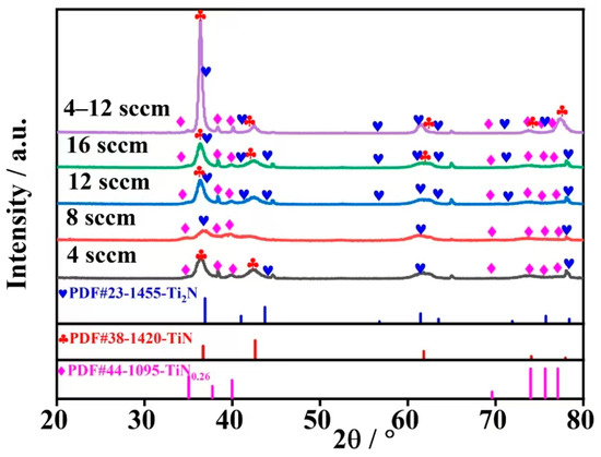
Figure 2.
XRD results of TiN/Ti multilayer coatings prepared with different nitrogen flow rates.
The variation in phase composition significantly influences the performance of the coatings fabricated at different nitrogen flow rates. For instance, existing research has shown that the TiN phase has a better ability to resist plastic deformation, and it exhibits superior resistance to plastic deformation and wear when subjected to erosive friction [31,32]. Current research indicates that TiN0.26 is a metastable nitride phase, whose presence contributes to enhancing the adhesion between the coating and the substrate [33,34,35,36]. It exhibits a compact hexagonal structure, similar to that of alpha-titanium, and has relatively lower hardness. A further refined analysis reveals that the intensity of the diffraction peaks for the coatings indeed increases with the nitrogen flow rate, indicating an enhancement in the crystallinity of the coating as the nitrogen content increases. This observed increase in crystallinity is likely linked to the improved stability and crystallization behavior of the titanium nitride phases within the coating. Additionally, within the specific nitrogen flow rate ranges of 12 sccm, 16 sccm, and 4–12 sccm, the XRD patterns confirm the coexistence of the TiN0.26, Ti2N, and TiN phases. The coexistence of these multiple phases, as supported by the existing literature [15,22,37], is suggested to contribute to the superior comprehensive performance of the coating, including enhanced hardness, wear resistance, and thermal stability.
3.2. Surface of TiN/Ti Multilayer Coatings
Figure 3 presents the surface roughness of the TiN/Ti multilayer coatings fabricated at different nitrogen flow rates. Surface roughness is closely related to the microstructure of the coating surface. The level of surface roughness is directly influenced by the number of circular pits and defects, such as coating delamination. As the nitrogen flow rate for the TiN/Ti multilayer coatings increases from 4 sccm to 16 sccm, the roughness values gradually decrease, indicating a smoother surface. Figure 3 clearly demonstrates the pivotal role of accurately controlling the nitrogen gas flow rate during the deposition of TiN/Ti multilayer coatings. The relationship between an increased nitrogen flow rate and a decrease in coating surface roughness is observed. This reduction in surface roughness is primarily due to the improved formation of a uniform TiN phase at elevated flow rates, which helps to counteract surface irregularities that may stem from suboptimal nitridation conditions. To provide a more detailed understanding, a precise nitrogen flow rate is essential for achieving the optimal incorporation of nitrogen into the coating. This balance prevents scenarios where insufficient nitridation could lead to an uneven surface or where excessive nitridation could cause phase separation. Furthermore, the controlled nitrogen flow facilitates a more structured arrangement of titanium and nitrogen atoms, leading to a smoother surface finish. This orderly arrangement is a direct result of the careful regulation of nitrogen supply, which is a critical factor in the deposition process that has been overlooked in previous studies, as noted by Lan Zhang et al. in their work on the structure control of high-quality coatings [38]. Existing research indicates that as the nitrogen flow rate for the TiN/Ti multilayer coatings increases, the surface roughness of the coatings gradually decreases. This phenomenon is due to the fact that at lower nitrogen flow rates, the coating surface is composed of sharp-edged flake structures. As the flow rate is increased, the surface structure transitions to a smoother flake pattern. Further increasing the nitrogen flow rate promotes the formation of triangular crystals [20]. The improvement of surface roughness is crucial for enhancing the erosion resistance of the coatings. Surfaces with lower roughness values fabricated at different nitrogen flow rates tend to have fewer defects, resulting in better sand erosion resistance. As shown in Figure 3, using a gradient nitrogen flow rate of 4–12 sccm can improve the surface quality of the TiN/Ti multilayer coatings to some extent, but the improvement is not as significant as that achieved with a single higher flow rate. Specifically, when a gradient flow rate of 4–12 sccm is applied, the surface roughness values of the TiN/Ti multilayer coatings fall between those at 16 sccm and other lower flow rates, indicating that the optimization effect of gradient flow rates on surface roughness has certain limitations.
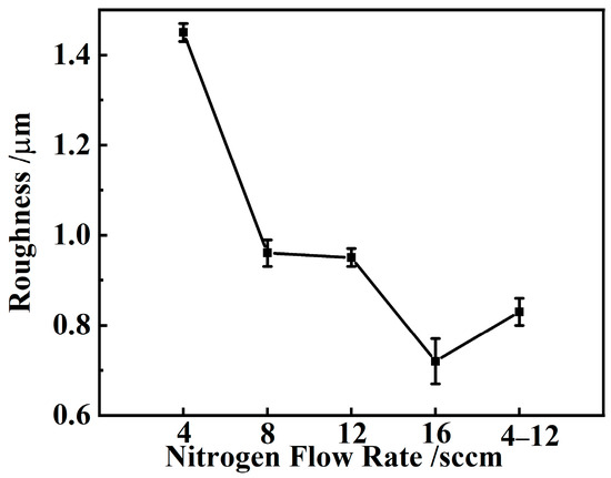
Figure 3.
Surface roughness values of TiN/Ti multilayer coatings fabricated at different nitrogen flow rates.
Figure 4a presents the surface morphology of the TiN/Ti multilayer coating fabricated at a nitrogen flow rate of 4 sccm, showcasing its initial state with inherent smoothness and distinct microstructural features that are stable and not influenced by external factors. Figure 4b provides a clear depiction of the coating’s thickness distribution, revealing its layered structure. The total thickness of the coating, as observed in Figure 4b, is measured at 10.86 μm, consisting of five alternating layers of TiN and Ti. The cross-sectional image demonstrates a regular pattern of alternating light and dark bands, indicative of the layered structure. The darker bands represent the TiN layers, while the lighter bands correspond to the Ti layers, arranged in a uniform and consistent manner throughout the coating. The TiN layers are approximately 1.92 μm thick, and the Ti layers are around 0.24 μm thick. Figure 4c indicates that with a significant increase in magnification to 8000 times, these images reveal the detailed microstructure of the TiN/Ti multilayer coating. The higher magnification images provide a clear view of the interlayer interfaces, demonstrating a continuous and uniform bond between layers, which is essential for the coating’s load-bearing capacity.
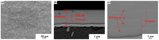
Figure 4.
Surface and cross-sectional morphologies of TiN/Ti multilayer coatings fabricated at 4 sccm nitrogen flow rate: (a) surface morphology; (b) SEM image of the cross-sectional morphology at a magnification of 4000×; (c) SEM image of the cross-sectional morphology at an 8000× magnification.
3.3. Mechanical Properties of TiN/Ti Multilayer Coatings
Figure 5 provides an in-depth analysis of the effects of different nitrogen flow rates on the hardness and elastic modulus of the TiN/Ti multilayer coating. Figure 5 visually presents the specific values of hardness and elastic modulus for coatings fabricated at different nitrogen flow rates. In terms of hardness, the measurements under the five different nitrogen flow conditions show minor fluctuations. The lowest hardness value, 19.63 GPa, was observed in the coating treated with gradient nitrogen flow, indicating that the gradient nitrogen flow helps to reduce the hardness of the coating, thereby improving its toughness. In contrast, the highest hardness value, 24.37 GPa, was recorded for the coating fabricated at a nitrogen flow rate of 16 sccm, although the overall variation in hardness values is not substantial. The variation in elastic modulus is more pronounced, with a larger range of values. At a nitrogen flow rate of 16 sccm, the elastic modulus of the coating reaches its maximum value of 219.84 GPa, indicating that the coating has the best elastic recovery ability at this flow rate. The elastic modulus is lowest under gradient nitrogen flow conditions, at 159.93 GPa, corresponding to its lowest hardness value. The reason for this is that when the nitrogen flow rate reaches 12 sccm, the coexistence of TiN, TiN0.26, and Ti2N phases leads to the coating possessing better mechanical properties. Honghong Zhang’s research indicates that when the hardness of the thin film is below the critical value of 23 GPa, the film exhibits poor resistance to sand erosion [22]. These findings underscore the significant impact of nitrogen flow rate on the mechanical properties of TiN/Ti multilayer coatings fabricated at different nitrogen flow rates. When the nitrogen flow rate is at its maximum (16 sccm), both hardness and elastic modulus reach their peak values. Conversely, when a gradient nitrogen flow rate is applied, the values for hardness and elastic modulus are at their minimum.
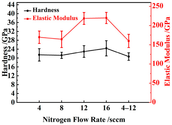
Figure 5.
Hardness and elastic modulus values of TiN/Ti multilayer coatings fabricated at different nitrogen flow rates.
3.4. Erosion Behavior of TiN/Ti Multilayer Coatings
Figure 6a–e, respectively, illustrate the mass loss of the TiN/Ti multilayer coatings fabricated at nitrogen flow rates of 4 sccm, 8 sccm, 12 sccm, 16 sccm, and a gradient of 4–12 sccm after exposure to sand erosion. The raw data of mass loss is shown in Table S1 of the supplementary file. By conducting a linear fit on these mass loss data for the TiN/Ti multilayer coatings fabricated at different nitrogen flow rates, a distinct straight line can be drawn. The magnitude of the slope of this line not only quantifies the erosion rate but also directly represents the relative strength of the erosion effect. By comparing the data in Figure 6a–e, it can be observed that as the nitrogen flow rate gradually increases, the mass loss of the coating after erosion shows a significant decreasing trend. When the nitrogen flow rate is set to 4 sccm, the mass loss of the coating is the greatest, reflecting its poorest erosion resistance performance. In contrast, when a gradient nitrogen flow rate of 4–12 sccm is used, the coating exhibits the smallest mass loss, reflecting the best erosion resistance performance. Figure 6a reveals that at the very beginning of the erosion process for the coating fabricated at 4 sccm nitrogen flow rate, the coating suffered severe damage early on, leading to significant mass loss, indicating coating spalling. In Figure 6b, it can be observed that during the initial phase of erosion for the coating fabricated at 8 sccm nitrogen flow rate, i.e., when the sand supply is less than 10 g, the coating has not yet spalled, and the mass loss is relatively small. However, when the sand supply accumulates to 10 g, the rate of mass loss increases sharply, signaling that the spalling of the coating began after 4 min of erosion. Figure 6c further illustrates that for the coating fabricated at 12 sccm nitrogen flow rate, when the sand supply is below 15 g, the mass loss remains at a low level, and the slope of the fitted curve is also small, indicating that the coating is still stable. However, when the sand supply reaches 15 g, there is a sudden change in the slope of the mass loss, and this sharp increase corresponds to the spalling of the coating after 6 min of erosion. Figure 6d,e show that for the coatings fabricated at a 16 sccm nitrogen flow rate or with a gradient flow condition of 4–12 sccm, the overall mass loss is small, indicating better erosion resistance compared to the coatings fabricated at lower nitrogen flow rates.
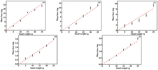
Figure 6.
The mass loss values of TiN/Ti multilayer coatings fabricated at different nitrogen flow rates under various sand supply values: (a) 4 sccm; (b) 8 sccm; (c) 12 sccm; (d) 16 sccm; (e) 4–12 sccm gradient flow.
Figure 7 provides an in-depth analysis of the linear fit slopes derived from the sub-figures in Figure 6, offering a precise representation of the erosion rates for the TiN/Ti multilayer coatings produced under various nitrogen flow rates. For the coatings fabricated at 16 sccm and within the 4–12 sccm gradient, the mass loss values were all below the 4 mg threshold, hence the slopes derived from the mass loss plots were directly adopted as the erosion rates. In contrast, for the coatings at 4 sccm, 8 sccm, and 12 sccm, the erosion rate was calculated differently. Utilizing the 4 mg demarcation, the erosion rate was determined by dividing the mass loss value prior to reaching this threshold by the corresponding sand supply volume. The experimental data show that as the nitrogen flow rate increases from 4 sccm to 8 sccm, 12 sccm, and 16 sccm, the corresponding erosion rate values decrease sequentially to 0.8 mg·g−1, 0.30 mg·g−1, 0.25 mg·g−1, and 0.12 mg·g−1. This clearly reveals an inverse relationship between nitrogen flow rate and erosion rate: the higher the nitrogen flow rate, the lower the erosion rate, indicating a significant enhancement in the coating’s erosion resistance performance. The erosion rate for the TiN/Ti multilayer coatings fabricated under gradient flow conditions drops to 0.07 mg·g−1, a result that highlights that, under the tested conditions, gradient flow can maximize the erosion resistance of the TiN/Ti multilayer coating. Further analysis of the trend in erosion rate values indicates that as the nitrogen flow rate increases from 4 sccm to 8 sccm, 12 sccm, and 16 sccm, the erosion rate values decrease significantly by 0.5, 0.05, and 0.13 mg·g−1, respectively. However, when comparing the 16 sccm nitrogen flow rate with the gradient flow, the reduction in erosion rate is only 0.05 mg·g−1, suggesting that at high nitrogen flow rates, the contribution of gradient flow to further improving erosion performance may be limited.
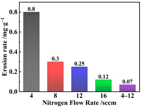
Figure 7.
The erosion rate values of TiN/Ti multilayer coatings fabricated at different nitrogen flow rates.
3.5. Erosion Failure Process Analysis
Figure 8a–e present a series of micrographs that illustrate the micro-morphology of the TiN/Ti multilayer coating fabricated at different nitrogen flow rates after erosion. Figure 8a shows the post-erosion surface condition of the coating fabricated at a nitrogen flow rate of 4 sccm. After the sand erosion process, the surface of this coating exhibits significant damage, with visible sand erosion pits and cracks, indicating the onset of structural degradation. Figure 8b illustrates the surface changes in the coating fabricated at an increased nitrogen flow rate of 8 sccm. The damage to the coating surface intensifies with the higher flow rate, marked by an increase in erosion cracks and the formation of large, ring-like pits, which suggest further structural damage. Figure 8c displays the surface of the coating fabricated at a nitrogen flow rate of 12 sccm, where erosion slides in various directions have emerged. These slides, appearing as strip-like or belt-like wear areas resulting from erosion, are deep and widely distributed, indicating plastic deformation in localized areas of the coating. Figure 8d presents the surface of the coating fabricated at a further increased nitrogen flow rate of 16 sccm. Here, minor erosion damage is observed, characterized by smaller pits and shallow slides, which are the result of the impact and friction caused by the high-speed nitrogen flow. Despite this, the lower surface roughness at this flow rate prevents significant damage, maintaining the coating’s integrity and protective performance. The reduced wear rate during erosion at this flow rate helps to preserve the coating’s smoothness and minimizes friction with external objects. Figure 8e shows the surface condition of the coating fabricated using a gradient nitrogen flow rate. Compared to coatings prepared at constant flow rates, the gradient application significantly reduces surface damage, resulting in only minor pits. This series of micrograph analyses underscores the significant effect of nitrogen flow rate during the fabrication process on the erosion resistance of the TiN/Ti multilayer coatings. As the nitrogen flow rate increases, surface damage generally escalates, while the application of a gradient flow rate may offer a more moderate erosion process, which is beneficial for preserving the coating’s integrity.
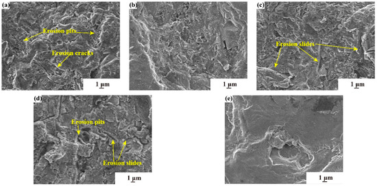
Figure 8.
SEM images of surface morphology of TiN/Ti multilayer coatings fabricated at different nitrogen flow rates with a sand supply of 25g: (a) 4 sccm; (b) 8 sccm; (c) 12 sccm; (d) 16 sccm; (e) 4–12 sccm.
Figure 9 presents a series of images detailing the cross-sectional morphological changes in the TiN/Ti multilayer coating fabricated at a nitrogen flow rate of 12 sccm under varying sand supply amounts. In these images, the brighter areas represent the TiN layers, while the darker areas are the Ti layers. As shown in Figure 9a, at a sand supply of 5 g, multiple lateral cracks have already appeared on the coating surface. These cracks penetrate through both the Ti and TiN layers, indicating that the coating’s adhesion strength begins to weaken under erosive action. With the sand supply increased to 15 g, as depicted in Figure 9b, the upper layer of the coating has undergone delamination, and vertical cracks are also observable. These vertical cracks interweave with the existing lateral cracks, leading to a layer-by-layer spalling of the coating and exacerbating the damage. When the sand supply further increases to 20 g, as shown in Figure 9c, the number of lateral cracks at the interface between the TiN and Ti layers significantly increases, and the depth of the cracks deepens. This expansion of cracks results in severe erosion damage to the TiN layer, while the Ti layer exhibits obvious delamination. At a sand supply of 25 g, as illustrated in Figure 9d, all layers of the coating except the Ti layer near the substrate have completely peeled off. At this stage, the junction of lateral and vertical cracks becomes particularly evident. The coating to the left of the junction has completely peeled off, while the coating to the right remains relatively intact. The progression of damage shown in Figure 9 underscores the intricate relationship between the mechanical properties of the coating and the environmental stressors it encounters. The delamination and spalling observed are indicative of a complex interplay between the intrinsic stress within the coating layers and the extrinsic forces exerted by the sand particles. It is noteworthy that delamination initiates at the weakest points within the coating, often related to the microstructure and chemical composition of the material [25,39,40]. The TiN/Ti multilayer coating, fabricated under a nitrogen flow rate of 12 sccm, exhibits a specific interlayer bonding strength critical to its resistance against erosive forces. As the sand supply escalates, the coating’s response to increased mechanical stress is manifested through the formation and propagation of cracks. The vertical cracks that emerge are not merely a result of the direct impact of sand particles, but also reflect the coating’s internal stress distribution, influenced by the fabrication process and the thermal expansion coefficients of the constituent materials. The lateral cracks are influenced by the shear stresses induced by the sand particles as they traverse the coating surface, highlighting the importance of the coating’s adhesion to the substrate. The detailed examination of the crack network in Figure 9d at the highest sand supply reveals a stark contrast between regions of complete delamination and those that remain bonded. This dichotomy suggests that the failure mechanism is not uniform across the coating but is governed by localized variations in material properties and stress concentrations. The intact region adjacent to the crack junction may be attributed to a higher degree of interlayer bonding or a more favorable microstructure that resists crack propagation [41,42].
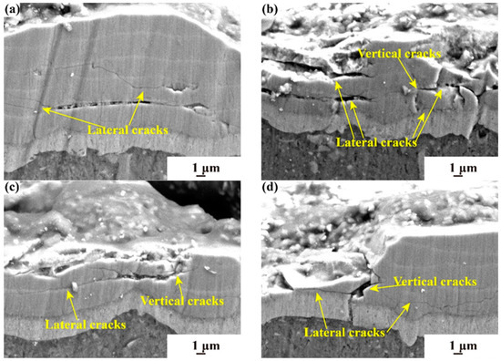
Figure 9.
SEM images of erosion failure process of TiN/Ti multilayer coatings fabricated with different sand supply and nitrogen flow rate of 12 sccm: (a) 5 g; (b) 15 g; (c) 20 g; (d) 25 g.
The SEM images in Figure 10 provide a compelling visual narrative of the progressive degradation of the TiN/Ti multilayer coating under increasing sand supply. The initial delamination observed at 10 g of sand (Figure 10a) is indicative of the coating’s vulnerability to mechanical stress, with the first layer’s thickness reduction serving as a quantitative measure of the coating’s resilience. As the sand supply escalates to 15 g (Figure 10b), the emergence of lateral cracks and the subsequent delamination of the first layer underscore the coating’s structural integrity being compromised. The failure of the second layer, influenced by these lateral cracks, suggests a cascading effect that propagates through the coating layers. The deepening and elongation of lateral cracks at a sand supply of 20 g (Figure 10c) are indicative of the coating’s ongoing struggle against the erosive forces. The significant reduction in coating thickness to 4.21 µm at 25 g of sand (Figure 10d) is a testament to the cumulative effect of erosion on the coating’s structural integrity. However, the observation that two layers remain intact, despite the extensive delamination, points to the heterogeneity in the coating’s response to erosion and the potential for localized reinforcement. A comparative analysis between Figure 8 and Figure 9 reveals the pivotal role of nitrogen flow rate in modulating the coating’s resistance to erosion. The increased nitrogen flow rate to 16 sccm results in a substantial decrease in the erosion rate value, suggesting that the interlayer bonding is enhanced, thereby slowing down the propagation of lateral cracks and reducing the extent of delamination [43].
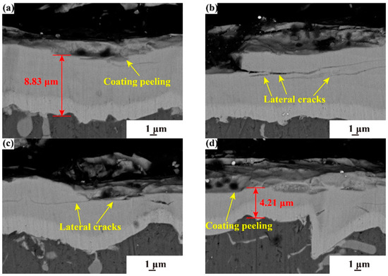
Figure 10.
SEM images of erosion failure process of TiN/Ti multilayer coatings fabricated with different sand supply and nitrogen flow rate of 16 sccm: (a) 10 g; (b) 15 g; (c) 20 g; (d) 25 g.
Figure 11 provides a series of SEM images that offer significant insights into the robustness of the TiN/Ti multilayer coating fabricated under gradient nitrogen flow rates. Even at a sand supply of 25 g, where vertical cracks are observed, the coating demonstrates an impressive damage tolerance, with damage primarily localized to the first layer. This localized damage pattern suggests that the gradient nitrogen flow rates have resulted in a more uniform and resilient microstructure, effectively mitigating the propagation of cracks throughout the coating. A detailed examination of the microstructure reveals a refined grain structure and reduced porosity in the coating fabricated under gradient nitrogen flow rates, which likely contribute to its enhanced erosion resistance. The hardness and fracture toughness of the coating, as measured by nanoindentation and other mechanical testing methods, further substantiate its superior mechanical properties. Comparative studies of the failure modes across different nitrogen flow rates highlight the unique advantage of the gradient flow approach. Previous studies have indicated that the controlled variation in nitrogen flow rate during fabrication appears to optimize the interlayer bonding and phase distribution, leading to a more damage-resistant coating structure [25,43].
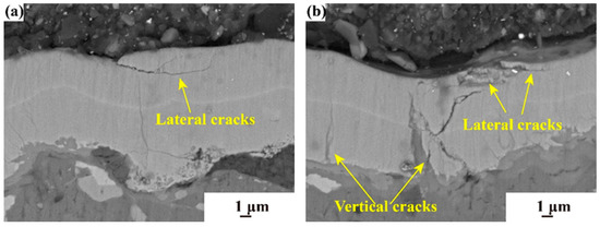
Figure 11.
SEM images of erosion failure process of TiN/Ti multilayer coatings fabricated with different sand supply and nitrogen flow rate of 4–12 sccm: (a) 15 g; (b) 25 g.
4. Conclusions
This study reveals the mechanical properties and erosion performance of TiN/Ti multilayer coatings prepared at different nitrogen flow rates (4 sccm, 8 sccm, 12 sccm, 16 sccm, and a gradient flow rate of 4–12 sccm), leading to the following conclusions:
- Nitrogen gas flow rate significantly affects the phase composition and mechanical properties of the coating: As the nitrogen gas flow rate increases, the phase composition of the coating transitions from TiN0.26 phase to a composite structure containing Ti2N and TiN, significantly enhancing the mechanical properties. The TiN/Ti coating prepared at a nitrogen gas flow rate of 16 sccm achieves peak hardness and elastic modulus values of 24.37 GPa and 219.84 GPa, respectively. Although the coatings under gradient flow conditions exhibit slightly lower hardness and elastic modulus, they still demonstrate good overall mechanical performance.
- Nitrogen gas flow rate significantly influences the surface roughness and erosion resistance of the coating: An increase in nitrogen gas flow rate leads to a reduction in surface roughness, thereby enhancing the erosion resistance. Coatings under a gradient nitrogen flow rate of 4–12 sccm have a moderate surface roughness, indicating that the optimization effect of gradient flow on surface roughness is limited. As the nitrogen gas flow rate increases, the mass loss of the coating decreases significantly. The coating prepared at a nitrogen gas flow rate of 4 sccm has the largest mass loss and an erosion rate of 0.8 mg·g−1, indicating poor erosion resistance. In contrast, the coating prepared under gradient nitrogen flow conditions has the smallest mass loss, with an erosion rate reduced to 0.07 mg·g−1, showing an excellent erosion resistance that is 14 times better than that of the coating prepared at a flow rate of 4 sccm.
- Different nitrogen gas flow rates result in different failure mechanisms of the coating: Under gradient nitrogen flow conditions, the erosion rate is significantly reduced to 0.07 mg·g−1, indicating that the gradient flow effectively enhances the erosion resistance of the TiN/Ti multilayer coating. Under these conditions, the coating damage is mainly limited to the small-scale spalling of the first layer, while the deeper structure remains intact. In contrast, the coating prepared at a nitrogen gas flow rate of 12 sccm experiences large-scale spalling due to the connection of lateral and vertical cracks, resulting in an increased erosion rate to 0.25 mg·g−1. The coating prepared at a nitrogen gas flow rate of 16 sccm, on the other hand, experiences direct spalling due to the expansion and deepening of horizontal cracks, but the erosion rate is reduced to 0.12 mg·g−1, suggesting that a higher nitrogen gas flow rate contributes to reducing coating spalling.
Supplementary Materials
The following supporting information can be downloaded at: https://www.mdpi.com/article/10.3390/coatings14091144/s1, Table S1: Mass loss of raw data.
Author Contributions
For this research article, the authors have contributed in the following capacities: Y.R. was instrumental in drafting the initial manuscript, managing data curation, conducting formal analysis, developing the methodology, and creating the software. Additionally, Y.R. played a pivotal role in reviewing and editing the manuscript. Z.Z. (Zhaolu Zhang) contributed significantly to the investigation phase of the research and was responsible for securing resources and validating the study’s findings. G.H. contributed significantly to the project through project administration, supervision, software development, and funding acquisition. Y.C. provided essential support through funding acquisition, supervision of the research, and overseeing the project’s administration. Y.Z. contributed to the visualization aspects of the project. Z.Z. (Zilei Zhang)’s contributions included funding acquisition, supervision, and enhancing the visualization of the research outcomes. All authors have read and approved the final version of the manuscript, ensuring that their individual contributions have been accurately acknowledged according to the CRediT taxonomy. All authors have read and agreed to the published version of the manuscript.
Funding
This work was financially supported by Industrial Technology Development Program of China (DEDP), and Shaanxi Province Postdoctoral Science Foundation (31271000000082), and Shaanxi Provincial Science and Technology Innovation Team (No.2024RS-CXTD-26), and “the Fundamental Research Funds for the Central Universities” (xzy012024021).
Institutional Review Board Statement
Not applicable.
Informed Consent Statement
Not applicable.
Data Availability Statement
The raw/processed data required to reproduce these findings cannot be shared at this time as the data also forms part of an ongoing study.
Acknowledgments
This work was financially supported by Industrial Technology Development Program of China (DEDP), and Shaanxi Province Postdoctoral Science Foundation (31271000000082), and Shaanxi Provincial Science and Technology Innovation Team (No.2024RS-CXTD-26), and “the Fundamental Research Funds for the Central Universities” (xzy012024021).
Conflicts of Interest
The authors declare that they have no conflicts of interest.
References
- Roa, J.J.; Jiménez-Piqué, E.; Martínez, R.; Ramírez, G.; Tarragó, J.M.; Rodríguez, R.; Llanes, L. Contact Damage and Fracture Micromechanisms of Multilayered TiN/CrN Coatings at Micro- and Nano-Length Scales. Thin Solid Film. 2014, 571, 308–315. [Google Scholar] [CrossRef]
- Ruan, H.; Wang, Z.; Wang, L.; Sun, L.; Peng, H.; Ke, P.; Wang, A. Designed Ti/TiN Sub-Layers Suppressing the Crack and Erosion of TiAlN Coatings. Surf. Coat. Technol. 2022, 438, 128419. [Google Scholar] [CrossRef]
- Wu, Y.; Li, Z.; Yang, W.; Zhu, S.; Meng, X.; Cai, Z. Fretting Wear Behavior of Ti/TiN Multilayer Film on Uranium Surface under Various Displacement Amplitudes. Trans. Nonferrous Met. Soc. China 2018, 28, 1593–1601. [Google Scholar] [CrossRef]
- Das, S.; Guha, S.; Ghadai, R.; Sharma, A. Influence of Nitrogen Gas over Microstructural, Vibrational and Mechanical Properties of CVD Titanium Nitride (TiN) Thin Film Coating. Ceram. Int. 2021, 47, 16809–16819. [Google Scholar] [CrossRef]
- Chen, J.; Li, H.; Beake, B.D. Load Sensitivity in Repetitive Nano-Impact Testing of TiN and AlTiN Coatings. Surf. Coat. Technol. 2016, 308, 289–297. [Google Scholar] [CrossRef]
- Demchyshyn, A.V.; Kurapov, Y.A.; Michenko, V.A.; Kostin, Y.G.; Goncharov, A.A.; Ternovoi, Y.G. Linear Vacuum ARC Evaporators for Deposition of Functional Multi-Purpose Coatings. In Emerging Applications of Vacuum-Arc-Produced Plasma, Ion and Electron Beams; Oks, E., Brown, I., Eds.; NATO Science Series; Springer: Dordrecht, The Netherlands, 2002; pp. 131–149. ISBN 978-94-010-0277-6. [Google Scholar]
- Zhang, H.; Li, Z.; He, W.; Ma, C.; Liao, B.; Li, Y. Mechanical Modification and Damage Mechanism Evolution of TiN Films Subjected to Cyclic Nano-Impact by Adjusting N/Ti Ratios. J. Alloys Compd. 2019, 809, 151816. [Google Scholar] [CrossRef]
- Yang, Z.; Chen, J.; He, G.; Liang, X.; Luo, S. Mechanical Properties and Sand Erosion Damage Mechanism of TiN/Ti Multilayer Coatings after Thermal Cycling Treatment. J. Mater. Eng. Perform. 2023, 32, 8775–8785. [Google Scholar] [CrossRef]
- Zhang, H.; Li, Z.; He, W.; Liao, B.; He, G.; Cao, X.; Li, Y. Damage Evolution and Mechanism of TiN/Ti Multilayer Coatings in Sand Erosion Condition. Surf. Coat. Technol. 2018, 353, 210–220. [Google Scholar] [CrossRef]
- Chen, J.; Ji, R.; Khan, R.H.U.; Li, X.; Beake, B.D.; Dong, H. Effects of Mechanical Properties and Layer Structure on the Cyclic Dynamic Loading of TiN-Based Coatings. Surf. Coat. Technol. 2011, 206, 522–529. [Google Scholar] [CrossRef]
- Bonu, V.; Jeevitha, M.; Praveen Kumar, V.; Barshilia, H.C. Nanolayered Multilayer Ti/TiN Coatings: Role of Bi-Layer Thickness and Annealing on Solid Particle Erosion Behaviour at Elevated Temperature. Surf. Coat. Technol. 2019, 357, 204–211. [Google Scholar] [CrossRef]
- Cao, X.; He, W.; Liao, B.; Zhou, H.; Zhang, H.; Tan, C.; Yang, Z. Sand Particle Erosion Resistance of the Multilayer Gradient TiN/Ti Coatings on Ti6Al4V Alloy. Surf. Coat. Technol. 2019, 365, 214–221. [Google Scholar] [CrossRef]
- Leyland, A.; Matthews, A. Thick Ti/TiN Multilayered Coatings for Abrasive and Erosive Wear Resistance. Surf. Coat. Technol. 1994, 70, 19–25. [Google Scholar] [CrossRef]
- Feuerstein, A.; Kleyman, A. Ti–N Multilayer Systems for Compressor Airfoil Sand Erosion Protection. Surf. Coat. Technol. 2009, 204, 1092–1096. [Google Scholar] [CrossRef]
- Huang, B.; Liu, L.; Du, H.; Chen, Q.; Liang, D.; Zhang, E.; Zhou, Q. Effect of Nitrogen Flow Rate on the Microstructure, Mechanical and Tribological Properties of CrAlTiN Coatings Prepared by Arc Ion Plating. Vacuum 2022, 204, 111336. [Google Scholar] [CrossRef]
- Wieciński, P.; Smolik, J.; Garbacz, H.; Kurzydłowski, K.J. Erosion Resistance of the Nanostructured Cr/CrN Multilayer Coatings on Ti6Al4V Alloy. Vacuum 2014, 107, 277–283. [Google Scholar] [CrossRef]
- Babur, M.Z.; Iqbal, Z.; Shafiq, M.; Naz, M.Y.; Makhlouf, M.M. Hybrid TiN-CCPN Coating of AISI-201 Stainless Steel by Physical Vapor Deposition Combined with Cathodic Cage Plasma Nitriding for Improved Tribological Properties. J. Build. Eng. 2022, 45, 103512. [Google Scholar] [CrossRef]
- Fang, Z.; Chen, J.; He, W.; Yang, Z.; Yuan, Z.; Geng, M.; He, G. Study on the Damage Mechanism of TiN/Ti Coatings Based on Multi-Directional Impact. Coatings 2019, 9, 765. [Google Scholar] [CrossRef]
- Bromark, M.; Hedenqvist, P.; Hogmark, S. The Influence of Substrate Material on the Erosion Resistance of TiN Coated Tool Steels. Wear 1995, 186–187, 189–194. [Google Scholar] [CrossRef]
- Lapitskaya, V.; Nikolaev, A.; Khabarava, A.; Sadyrin, E.; Antipov, P.; Abdulvakhidov, K.; Aizikovich, S.; Chizhik, S. The Influence of Nitrogen Flow on the Stoichiometric Composition, Structure, Mechanical, and Microtribological Properties of TiN Coatings. Materials 2024, 17, 120. [Google Scholar] [CrossRef]
- Yang, Z.; Ren, Y.; Zhang, Y.; Zhang, Z.; He, G.; Zhang, Z. Structure Optimization and Failure Mechanism of Metal Nitride Coatings for Enhancing the Sand Erosion Resistance of Aluminum Alloys. Coatings 2023, 13, 2074. [Google Scholar] [CrossRef]
- Zhang, H.; Li, Z.; Ma, C.; He, W.; Cao, X.; Li, Y. The Anti-Sand Erosion Performance of TiN Films Fabricated by Filtered Cathodic Vacuum Arc Technique at Different Nitrogen Flow Rates. Ceram. Int. 2019, 45, 10819–10825. [Google Scholar] [CrossRef]
- Xue, X.; Wang, S.; Zeng, C.; Bai, H.; Li, L.; Wang, Z. Buckling-Delamination and Cracking of Thin Titanium Films under Compression: Experimental and Numerical Studies. Surf. Coat. Technol. 2014, 244, 151–157. [Google Scholar] [CrossRef]
- Phani, P.S.; Oliver, W.C.; Pharr, G.M. Understanding and Modeling Plasticity Error during Nanoindentation with Continuous Stiffness Measurement. Mater. Des. 2020, 194, 108923. [Google Scholar] [CrossRef]
- Chiba, Y.; Ichimura, H. Effect of Surface-Roughness of Substrates on Residual-Stress of Tin Coating. Nippon. Seramikkusu Kyokai Gakujutsu Ronbunshi-J. Ceram. Soc. Jpn. 1995, 103, 162–166. [Google Scholar] [CrossRef][Green Version]
- Miletic, A.; Terek, P.; Kovacevic, L.; Vilotic, M.; Kakas, D.; Skoric, B.; Kukuruzovic, D. Influence of Substrate Roughness on Adhesion of TiN Coatings. J. Braz. Soc. Mech. Sci. Eng. 2014, 36, 293–299. [Google Scholar] [CrossRef]
- Bousser, E.; Martinu, L.; Klemberg-Sapieha, J.E. Solid Particle Erosion Mechanisms of Protective Coatings for Aerospace Applications. Surf. Coat. Technol. 2014, 257, 165–181. [Google Scholar] [CrossRef]
- Bousser, E.; Martinu, L.; Klemberg-Sapieha, J.E. Solid Particle Erosion Mechanisms of Hard Protective Coatings. Surf. Coat. Technol. 2013, 235, 383–393. [Google Scholar] [CrossRef]
- Borawski, B.; Singh, J.; Todd, J.A.; Wolfe, D.E. Multi-Layer Coating Design Architecture for Optimum Particulate Erosion Resistance. Wear 2011, 271, 2782–2792. [Google Scholar] [CrossRef]
- Iwai, Y.; Honda, T.; Yamada, H.; Matsubara, T.; Larsson, M.; Hogmark, S. Evaluation of Wear Resistance of Thin Hard Coatings by a New Solid Particle Impact Test. Wear 2001, 251, 861–867. [Google Scholar] [CrossRef]
- Wu, L.; Zhang, D.; Zheng, B.; Yu, Z. Corrosion and Wear Resistance of TiN/TiO2 Composite Ceramic Coatings Deposited by Supersonic Arc Spraying. Ceram. Int. 2024, 50, 18655–18666. [Google Scholar] [CrossRef]
- Zhang, P.; Cheng, Q.; Yi, G.; Wang, W.; Liu, Y. The Microstructures and Mechanical Properties of Martensite Ti and TiN Phases in a Ti6Al4V Laser-Assisted Nitriding Layer. Mater. Charact. 2021, 178, 111262. [Google Scholar] [CrossRef]
- Gao, Z.; Zhang, Z.; Zhang, X.; Kulczyk-Malecka, J.; Liu, H.; Kelly, P.; Withers, P.J.; Xiao, P. A Conformable High Temperature Nitride Coating for Ti Alloys. Acta Mater. 2020, 189, 274–283. [Google Scholar] [CrossRef]
- Zhou, Q.; Ou, Y.; Li, F.; Ou, C.; Xue, W.; Liao, B.; Hua, Q.; Xu, Y.; Cao, J.; Qu, G. Friction and Wear of Hard Yet Tough TiN Coatings Deposited Using High-Power Impulse Magnetron Sputtering. Coatings 2024, 14, 598. [Google Scholar] [CrossRef]
- Granda-Gutiérrez, E.E.; Millán-Flores, H.; López-Callejas, R.; de la Piedad-Beneitez, A.; Muñoz-Castro, A.E.; Valencia, A.R.; Mercado-Cabrera, A.; Peña-Eguiluz, R.; Barocio, S.R. Superficial Characterization of a TiO2—TiN0.26 Layer Implanted in Titanium. Superf. Y Vacío 2007, 20, 11–16. [Google Scholar]
- Chen, J.; Yang, Y.; Pan, Y.; You, Y.; Hu, L.; Hu, M. Wear Resistance Performance of High Entropy Alloy–Ceramic Coating Composites Synthesized via a Novel Combined Process. Chin. J. Chem. Eng. 2023, 57, 202–213. [Google Scholar] [CrossRef]
- Logothetidis, S.; Alexandrou, I.; Kokkou, S. Optimization of TiN Thin Film Growth with in Situ Monitoring: The Effect of Bias Voltage and Nitrogen Flow Rate. Surf. Coat. Technol. 1996, 80, 66–71. [Google Scholar] [CrossRef]
- Zhang, L.; Shen, Y.-Q.; Zhao, Y.; Chen, S.-N.; Ouyang, X.; Zhang, X.; Liang, H.; Liao, B.; Chen, L. Structure Control of High-Quality TiAlN Monolithic and TiAlN/TiAl Multilayer Coatings Based on Filtered Cathodic Vacuum Arc Technique. Surf. Interfaces 2023, 38, 102836. [Google Scholar] [CrossRef]
- Trakhtenberg, I.S.; Vladimirov, A.B.; Plotnikov, S.A.; Rubshtein, A.P.; Vykhodets, V.B.; Bakunin, O.M. Effect of Adhesion Strength of DLC to Steel on the Coating Erosion Mechanism. Diam. Relat. Mater. 2001, 10, 1824–1828. [Google Scholar] [CrossRef]
- Sharma, R.K.; Das, R.K.; Kumar, S.R. Effect of Chromium Content on Microstructure, Mechanical and Erosion Properties of Fe-Cr-Ti-Mo-C-Si Coating. Surf. Interfaces 2021, 22, 100820. [Google Scholar] [CrossRef]
- Syamsundar, C.; Chatterjee, D.; Kamaraj, M.; Maiti, A.K. Erosion Characteristics of Nanoparticle-Reinforced Polyurethane Coatings on Stainless Steel Substrate. J. Mater. Eng. Perform 2015, 24, 1391–1405. [Google Scholar] [CrossRef]
- Wheeler, D.W.; Wood, R.J.K. Erosion of Hard Surface Coatings for Use in Offshore Gate Valves. Wear 2005, 258, 526–536. [Google Scholar] [CrossRef]
- Wang, S.; Li, Z.; Zhang, H.; Liang, X.; He, W.; Chen, Y.; Wu, Y.; Li, B. Study on the Sand Erosion Resistance of ZrN and ZrAlSiN Coatings. Surf. Coat. Technol. 2024, 488, 131081. [Google Scholar] [CrossRef]


Disclaimer/Publisher’s Note: The statements, opinions and data contained in all publications are solely those of the individual author(s) and contributor(s) and not of MDPI and/or the editor(s). MDPI and/or the editor(s) disclaim responsibility for any injury to people or property resulting from any ideas, methods, instructions or products referred to in the content. |
© 2024 by the authors. Licensee MDPI, Basel, Switzerland. This article is an open access article distributed under the terms and conditions of the Creative Commons Attribution (CC BY) license (https://creativecommons.org/licenses/by/4.0/).