Article

Thermal Corrosion Properties of Composite Ceramic Coating Prepared by Multi-Arc Ion Plating

1
School of Intelligent Manufacturing and Information, Jiangsu Shipping College, Nantong 226010, China
2
Jiangsu Linlong New Material Co., Ltd., Wuxi 214000, China
3
Jiangsu Key Laboratory of Atmospheric Environment Monitoring and Pollution Control, Collaborative Innovation Center of Atmospheric Environment and Equipment Technology, School of Environmental Science and Engineering, Nanjing University of Information Science and Technology, Nanjing 210044, China
4
College of Materials Science and Technology, Nanjing University of Aeronautics and Astronautics, Nangjing 211100, China
*
Author to whom correspondence should be addressed.
Coatings 2024, 14(9), 1150; https://doi.org/10.3390/coatings14091150
Submission received: 6 August 2024 / Revised: 2 September 2024 / Accepted: 5 September 2024 / Published: 7 September 2024
(This article belongs to the Section Ceramic Coatings and Engineering Technology)

Abstract

:
In this study, a NiCr/YSZ coating was applied to a γ-TiAl surface using multi-arc ion plating technology to enhance its high-temperature performance and explore the mechanisms of high-temperature oxidation and thermal corrosion. The thermal corrosion properties of the γ-TiAl matrix and NiCr/YSZ coating were investigated at 850 °C and 950 °C using a constant-temperature corrosion test in a 75% Na2SO4 + 25% NaCl mixture. The results indicate that after 100 h, the thermal corrosion weight gain of the coating samples was 70.1 mg/cm2 at 850 °C and 118.2 mg/cm2 at 950 °C. At these temperatures, sulfide formation on the surface increases, leading to a loose and porous surface. After 100 h of high-temperature corrosion at 850 °C, the primary oxidation product on the surface of the coating was tetragonal-ZrO2. At 950 °C, Y2O3, which mainly acts as a stabilizer in YSZ, reacted with Na2SO4, resulting in the continuous consumption of Y2O3. This reaction caused a substantial amount of tetragonal-ZrO2 to transform into monoclinic-ZrO2, altering the volume of the ceramic layer, which induced internal stress, crack propagation, and minor spallation. A continuous and dense internal thermally grown oxide (TGO) layer effectively impeded the diffusion of molten salt substances and oxygen, thereby significantly improving the thermal corrosion resistance of the thermal barrier coating.

1. Introduction

Due to its high specific strength, elastic modulus, and ability to maintain sufficient rigidity and strength at high temperatures, γ-TiAl is frequently used in high-temperature applications, such as marine gas turbines and aircraft engines [1,2]. However, at temperatures exceeding 650 °C, the free energy of TiO2 and Al2O3 becomes comparable, facilitating selective oxidation during high-temperature oxidation. Consequently, a mixed oxide film composed of TiO2 and Al2O3 forms on the surface. The incorporation of a significant amount of TiO2 inevitably results in a porous structure in the mixed oxide film, which fails to effectively impede oxygen diffusion. As a result, the γ-TiAl alloy exhibits insufficient resistance to oxidation above 650 °C. Moreover, the fuels used in these engines often contain impurities, such as Na and S, which can adhere to the surface of TiAl alloys and cause thermal corrosion due to the alloy’s low resistance to such corrosion [3,4].
Rather than developing entirely new high-temperature corrosion-resistant material, applying a protective coating on the surface of the base alloy is a more practical approach [5]. With the aid of diverse processing techniques, scholars have successfully developed a wide range of protective coatings, thereby significantly enhancing the longevity of the substrate [6,7]. Common high-temperature protective coatings include diffusion coatings, overlay coatings (such as MCrAlY coatings), and thermal barrier coatings [8,9,10,11,12]. Among them, thermal barrier coatings are considered one of the most advanced and promising options due to their ability to extend engine life, improve engine power, and reduce fuel consumption.
Based on their working environment and performance requirements, thermal barrier coatings are mainly categorized into three structural systems: double-layer, multi-layer, and gradient. Double-layer thermal barrier coatings are the most widely used and have the most mature preparation technology. They typically consist of an MCrAlY (where M is Ni, Co, or Ni+Co) intermediate bonding layer and a Y2O3-stabilized ZrO2 (YSZ) ceramic thermal insulation layer [13,14,15,16].
Plasma spraying and electron beam physical vapor deposition (EB-PVD) are the two main techniques used for preparing the thermal barrier coatings [17,18]. Plasma spraying involves the continuous impact, spreading, and solidification of molten droplets, resulting in a flaky coating with numerous pores and low thermal conductivity. This method often incorporates large amounts of slag and foreign pollutants in the coating. At high temperatures, corrosion or oxidation can occur at these defects, which can initiate cracks and ultimately cause coating failure [19,20]. In contrast, EB-PVD offers strong chemical bonding between the coating and the substrate, resulting in high bonding strength. However, it suffers from insufficient bulk density of the material due to rapid evaporation and shadowing effects [18,21,22].
Multi-arc ion plating technology is recognized for its high deposition efficiency, uniform and dense coatings, excellent conformal coverage, controllable coating preparation temperature, sufficient atomic diffusion, strong metallurgical bonding between the coating and substrate, and high bonding strength of the coating [23,24]. Recent advancements in multi-arc ion plating technology have enabled the development of various high-temperature protective coatings on the surface of γ-TiAl alloys, including aluminum coatings, chromium coatings, alloy coatings such as MCrAlX (M = Ni, Co; X = Y, Hf), oxide coatings such as Cr2O3 coatings, and composite coatings such as NiCrAlY/Al [25,26,27,28,29].
In this study, a NiCr/YSZ coating was applied to a γ-TiAl surface using multi-arc ion plating. The thermal corrosion resistance of the coating was evaluated by analyzing the thermal corrosion kinetics curves, surface and cross-sectional morphology, and corrosion products at different temperatures.

2. Experiment

A NiCr/YSZ coating was applied to cast γ-TiAl alloy (composition shown in Table 1; 14 × 14 × 5 mm3) using multi-arc ion plating. After grinding and polishing, the surface roughness of the substrate was Ra ≤ 0.8. The multi-arc ion plating equipment used in this experiment was produced by Beijing Taikono Company. A NiCr alloy target (mass fraction: 3:2, purity: 99.99%) was used as the source material to prepare the NiCr alloy bonding layer, whereas a ZrY alloy target (92:8 mass fraction) was used to prepare the YSZ coatings. The oxygen-to-argon flow ratio was maintained at 1:10, and the chamber pressure was set to 0.7 Pa. The process parameters were as follows: a bias voltage of −200 V, an arc current of 80 A, a working pressure of 0.7 Pa, and a chamber temperature of 400 °C.
Thermal corrosion tests were conducted using a salt coating method. The substrate and coated samples were preheated with an alcohol lamp. A brush dipped in saturated Na2SO4 aqueous solution was then used to apply a salt coating of 3.5 mg/cm2. The thermal corrosion tests were performed in an SX-49 box furnace (Tianjin Test Instrument Co., Ltd., Tianjin, China) at 850 °C and 950 °C for 100 h. The samples were removed every 10 h, immersed in boiling water for 30 min, and then dried and weighed after removing the salt film. Subsequently, the salt coating was reapplied using the original method to complete one thermal corrosion cycle.
During the tests, the weight gain of the samples was measured using an electronic analytical balance (Shanghai Heaven Precision Instrument Co., Ltd., FA-1004; accuracy 0.1 mg, Shanghai, China) [30,31]. The microstructure and composition of the samples before and after thermal corrosion were examined using scanning electron microscopy (SEM; FEI Quanta200, Shanghai, China) combined with energy-dispersive X-ray spectroscopy (EDS; OXFORD Xplore30, Shanghai, China). The phase structure of the substrate and coating was analyzed using X-ray diffraction (XRD; Bruker D8-ADVANCE, Beijing, China), with the following test parameters: a tube voltage of 50 kV, a tube current of 40 mA, a scanning range of 10–100°, a Cu Kα radiation source, a step size of 0.02°, and an acquisition time of 8 s per step.

3. Results

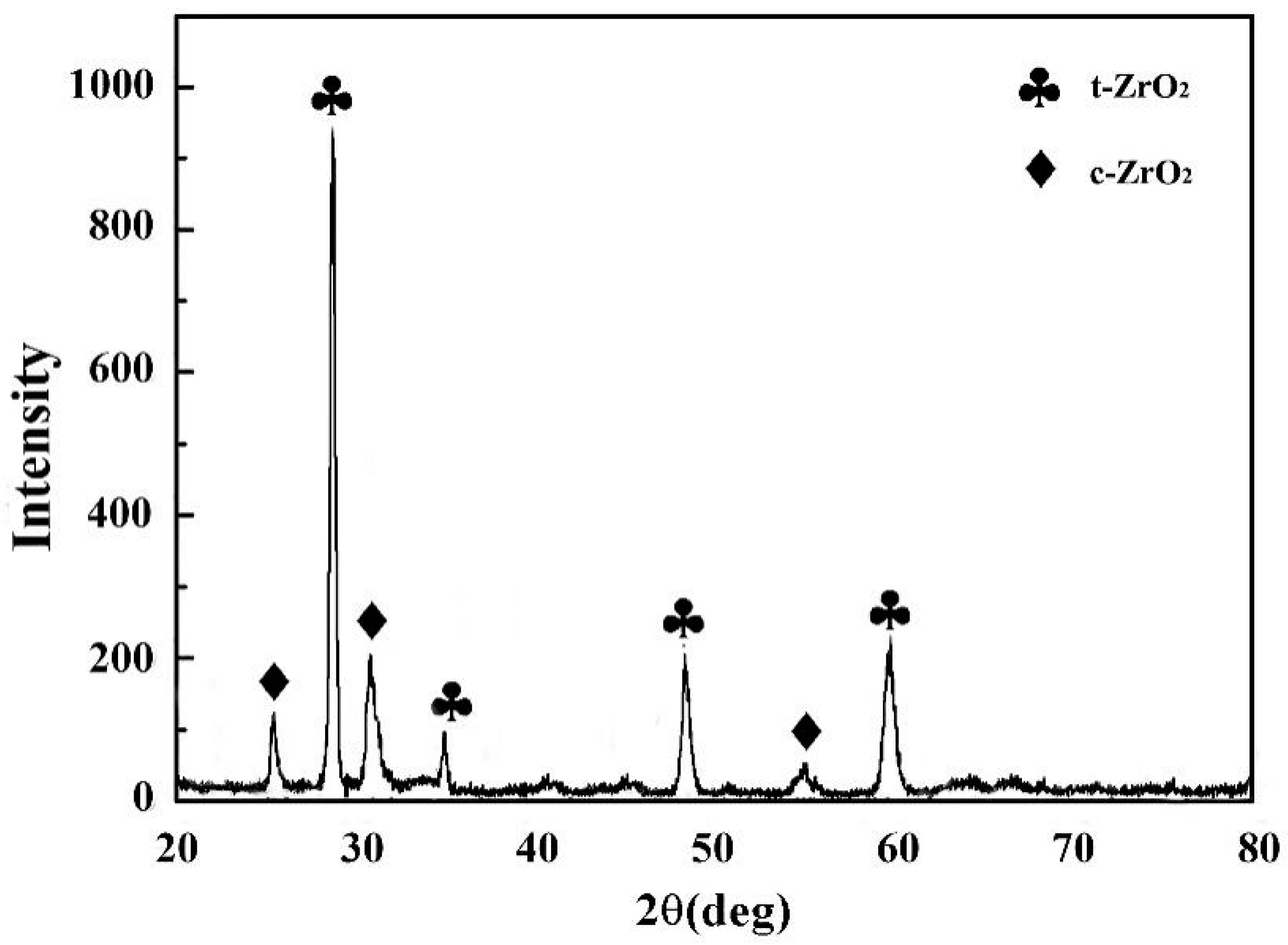
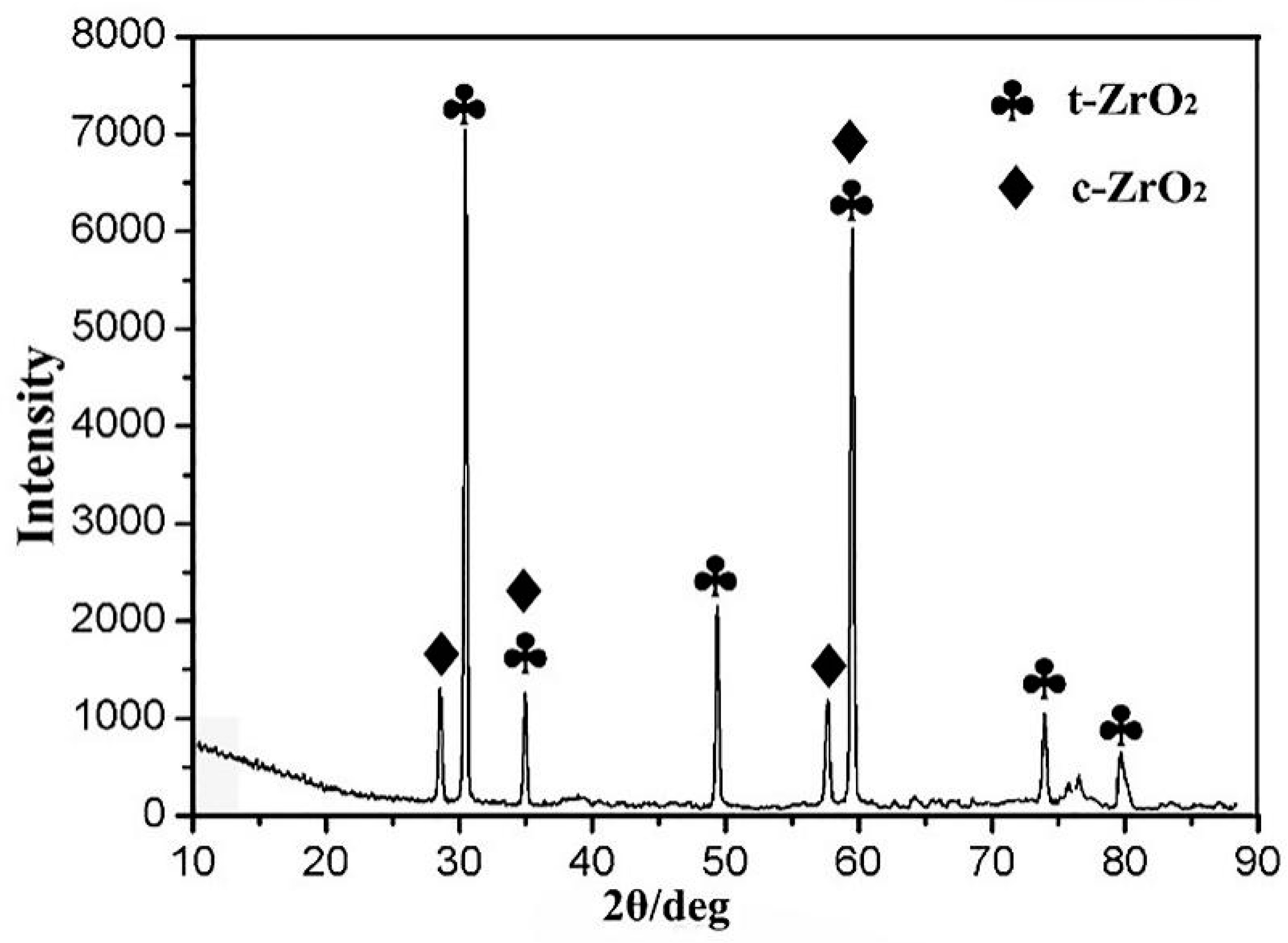
3.1. Microstructure and Surface Morphology of Coatings

Figure 1a shows an SEM image of the NiCr/YSZ coating obtained by multi-arc ion plating at 5000× magnification. The image reveals droplets with a diameter of approximately 2–4 μm that have solidified and attached to the surface of the coating. This results in surface unevenness, which is likely attributed to the high bias voltage, ion bombardment, and droplet impact. Although this unevenness is a typical feature and a major drawback of multi-arc ion plating, the overall appearance of the coating remained smooth and compact, with no visible defects, such as holes or cracks.
The EDS analysis results in Figure 1b indicate that the coating surface consists of a YSZ ceramic layer. The atomic mass ratio of Y to Zr on the coating surface was approximately 5:66, which is higher than the target mass ratio of 8:92. This discrepancy is ascribed to the segregation of components due to varying atomic sputtering rates. Specifically, Zr ions on the surface of the target initially underwent oxidation, which affected the sputtering yield of Zr ions and consequently reduced the amount of Zr in the coating.
Figure 2 shows the cross-sectional microstructure of the NiCr/YSZ coating, which is primarily composed of two layers: an 8 μm YSZ ceramic layer on the surface and a 3 μm NiCr adhesive layer between the YSZ ceramic layer and the γ-TiAl substrate. The NiCr coating was flat, compact, and free of significant defects. The inner side of the YSZ thermal barrier coating was tightly bonded to the NiCr layer without any pores or holes. However, the outer surface of the YSZ layer was uneven due to ion and metal droplet bombardment during ion sputtering. Overall, the intermediate NiCr layer between the coating and substrate was flat, compact, and free of gaps, holes, and impurities.
The XRD pattern (Figure 3) shows that ZrO2 in the YSZ thermal barrier coating was predominantly composed of a tetragonal phase (t-phase), with some cubic phase (c-phase). Pure ZrO2 was stable at temperatures around 1443–2643 K. However, the addition of Y2O3 stabilized the t-phase and restricted phase changes, with minimal impact on the thermal conductivity of ZrO2. The dense YSZ contained numerous oxygen vacancies, replacement atoms, and other point defects, which stabilized the t-phase even at room temperature. Consequently, the t-ZrO2 in the YSZ thermal barrier coating remained stable and resistant to failure, indicating enhanced thermal insulation performance and high-temperature oxidation resistance of the coating.

3.2. Thermal Corrosion at 850 °C

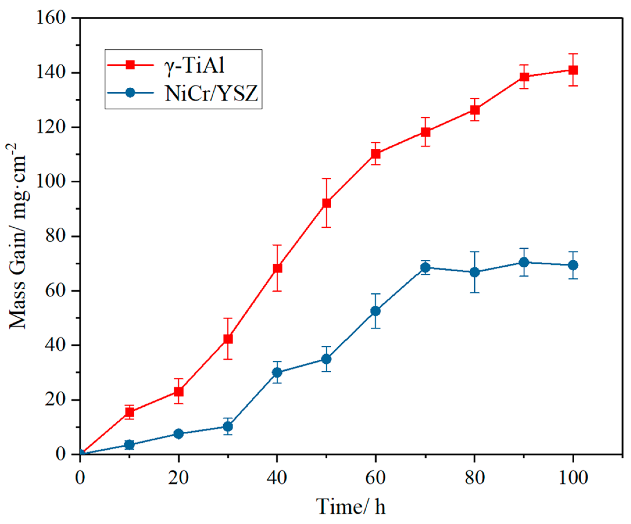
3.2.1. Thermal Corrosion Kinetics Curve

Figure 4 shows the thermal corrosion kinetics curve for the γ-TiAl substrate and the NiCr/YSZ coating when exposed to a 75% Na2SO4 + 25% NaCl mixture at 850 °C. The curve exhibits two distinct stages: an incubation stage and an acceleration stage. During the initial thermal corrosion stage, both samples experienced relatively low weight gain, resulting in a smoother kinetic curve. This stage, lasting for approximately 30 h at 850 °C, represents the incubation period of thermal corrosion. In the acceleration stage, the weight gain of the samples continuously increased over time. Consequently, the curve exhibits a linear progression. The weight gain also increased with temperature.
The NiCr/YSZ-coated samples exhibited slower weight gain compared to the γ-TiAl substrate, and the rate of weight gain for the NiCr/YSZ-coated sample remained extremely low. After 100 h of thermal corrosion, the weight gain of the γ-TiAl matrix was 141.4 mg/cm2, which is significantly higher than that of the NiCr/YSZ coating. The weight gain of the NiCr/YSZ-coated sample (Figure 4) was 70.1 mg/cm2, which is only 49.5% of that of the γ-TiAl matrix. This indicates that the NiCr/YSZ coating substantially enhancesd the thermal corrosion performance of γ-TiAl when exposed to the Na2SO4/NaCl mixture at 850 °C.

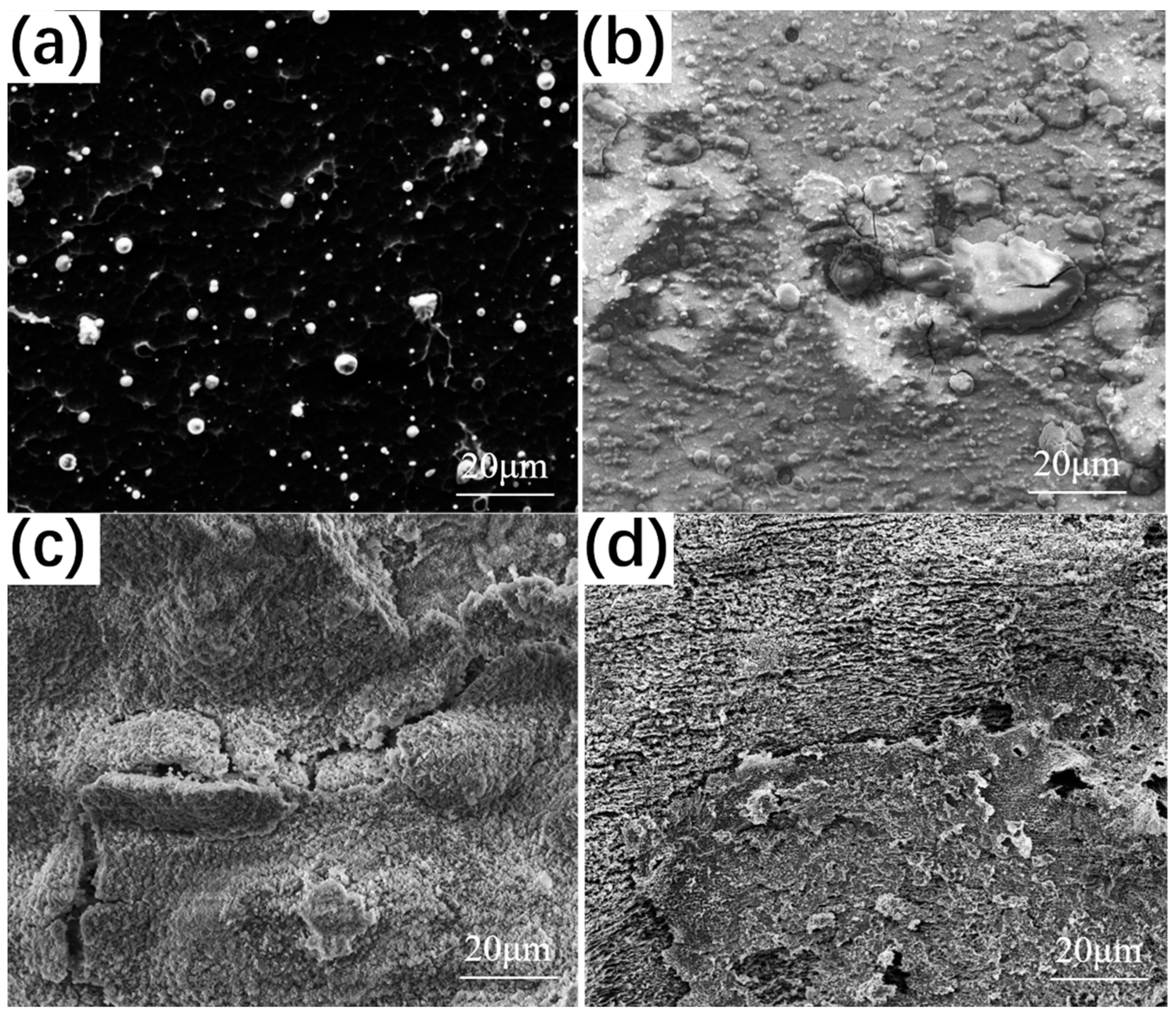
3.2.2. Surface Morphology after Thermal Corrosion

Figure 5 shows the surface micromorphology of the NiCr/YSZ-coated samples after thermal corrosion in Na2SO4/NaCl mixture at 850 °C for 0, 10, 40, and 100 h. As depicted in Figure 5b, after 10 h of thermal corrosion, the surface of the NiCr/YSZ coating became loose and porous, and some areas exhibited exfoliation and corrosion pits, with small, dispersed lumpy grains. At this stage, the coating was still in the incubation phase of thermal corrosion and exhibited high corrosion resistance. Figure 5c illustrates that after 40 h of thermal corrosion, the coating surface became looser, with more pronounced peeling. Some areas show reticular corrosion holes, where small particles were mixed. Figure 5d shows that after 100 h of thermal corrosion, the coating surface was completely cracked.

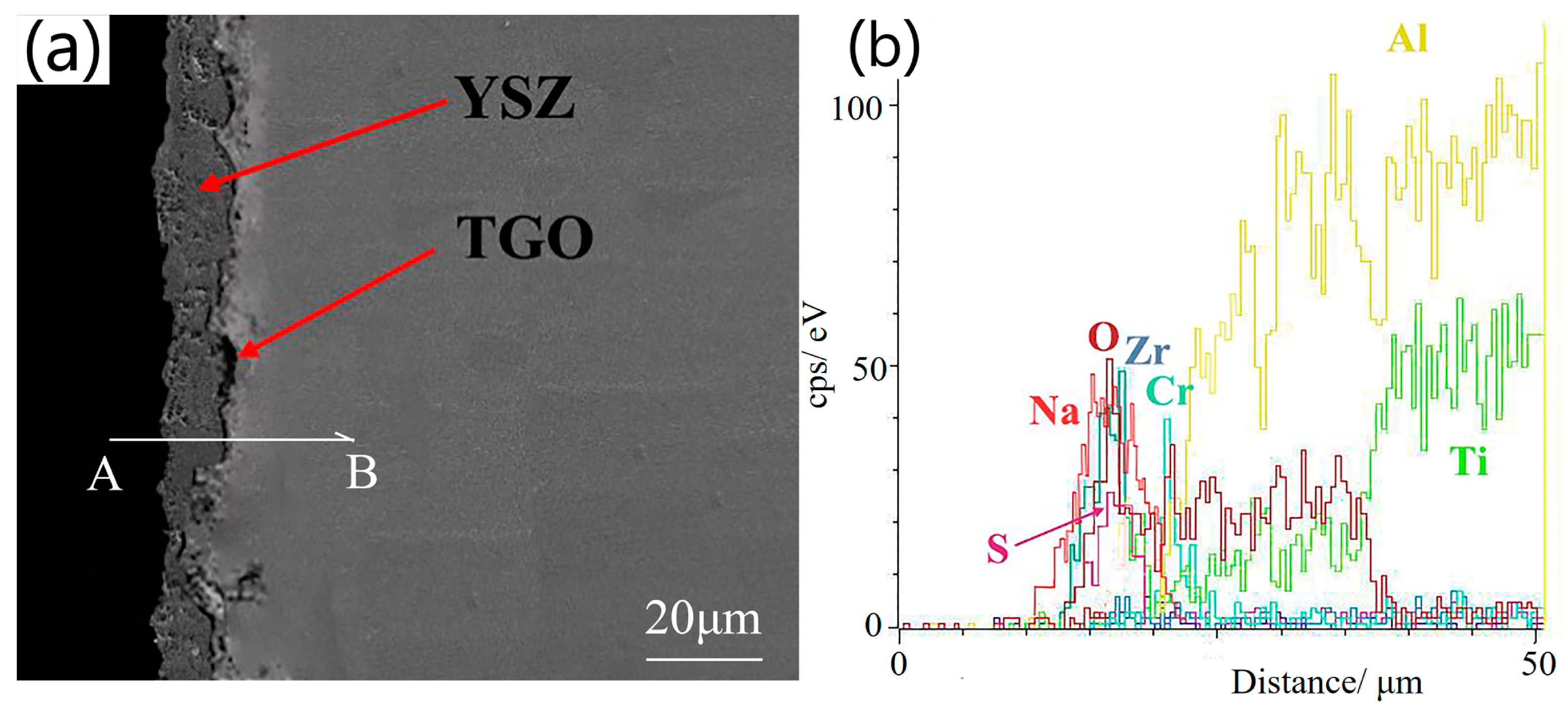
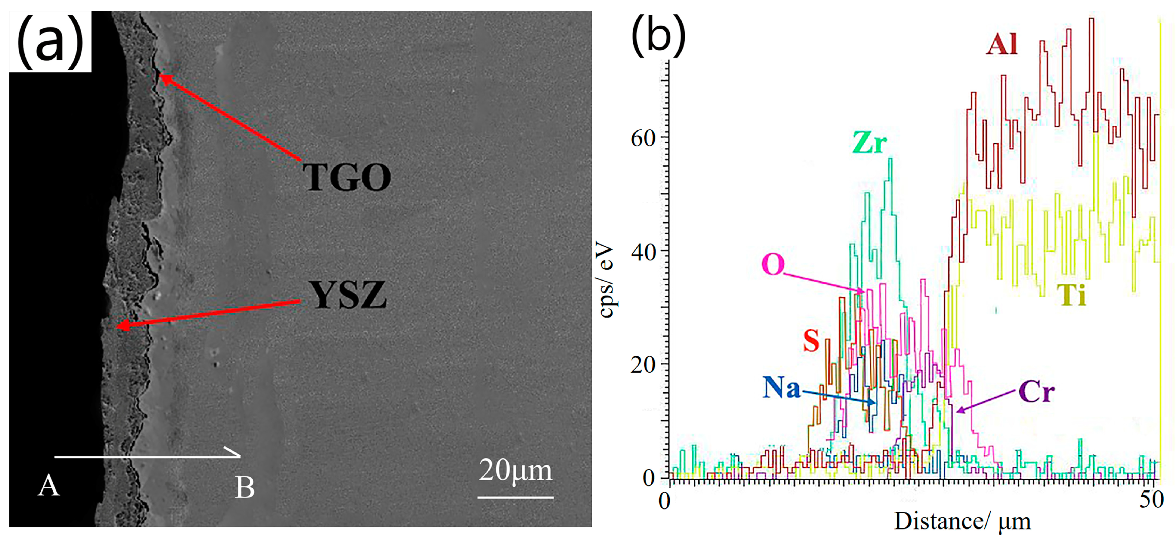
3.2.3. Cross-Sectional Microstructure after Thermal Corrosion

Figure 6a shows a cross-sectional micrograph of the NiCr/YSZ coating after 100 h of thermal corrosion at 850 °C. The image reveals that the coating tends to thicken due to the increased volume of oxide sulfides generated on the surface (Figure 6b). The YSZ coating was relatively loose compared to the non-corroded thermal barrier coating, with increased porosity along with cracks and voids that facilitate oxygen diffusion into the interior via these loose cracks. Consequently, the thermally grown oxide (TGO) layer inside the coating also became thicker, measuring approximately 3 μm.

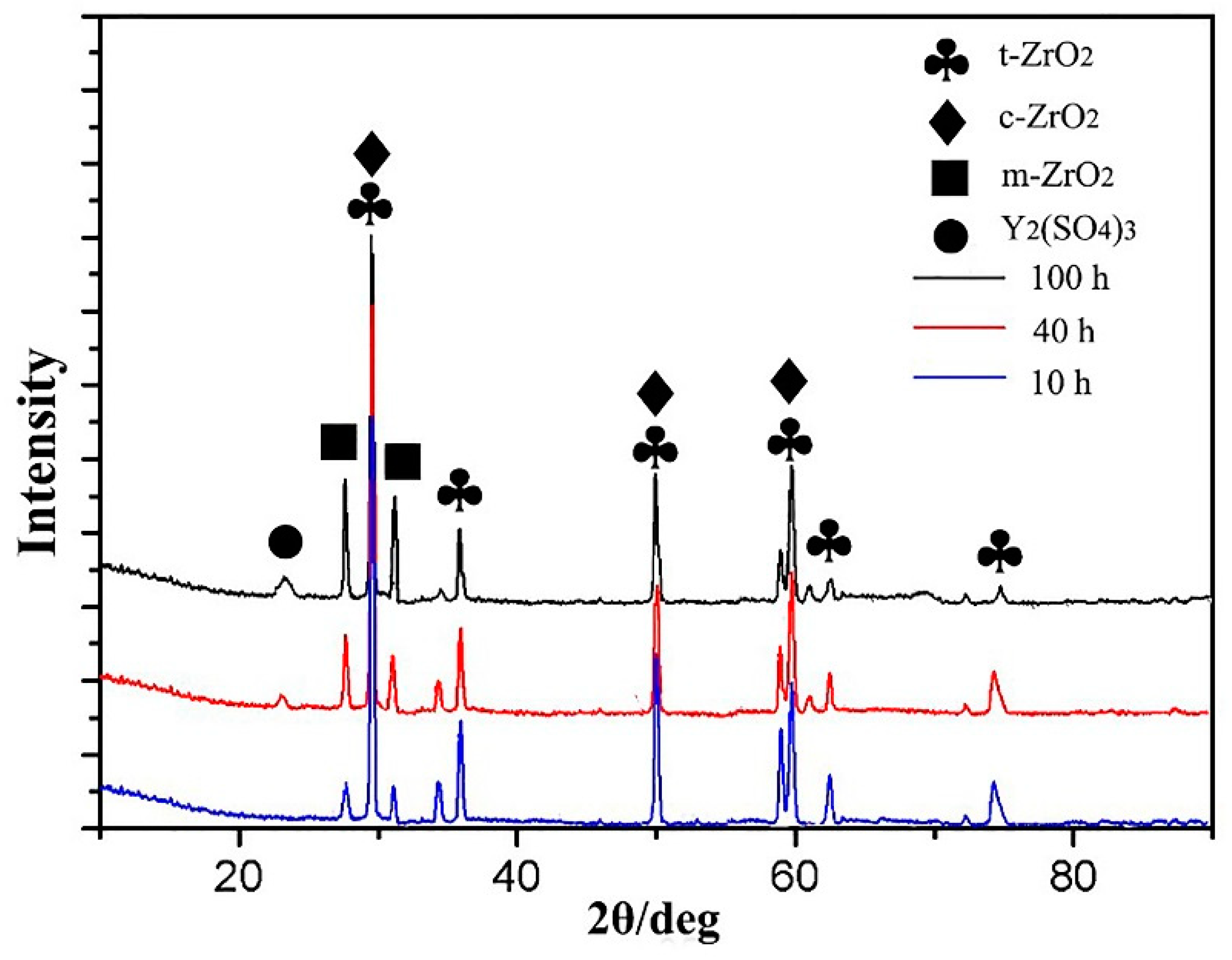
3.2.4. Thermal Corrosion Products

Figure 7 presents the XRD pattern of the NiCr/YSZ-coated samples after thermal corrosion in a Na2SO4/NaCl mixture at 850 °C for 100 h. After thermal corrosion, the predominant phase on the surface of the samples remained tetragonal, with some cubic phase. No monoclinic phase ZrO2 diffraction peaks were observed. This suggests that Y primarily exists as Y2O3 after thermal corrosion, providing good thermal corrosion resistance. In thermal barrier coatings, the transformation of tetragonal (t) to monoclinic (m) phase ZrO2 can increase stress within the ceramic layer and expand its volume. Therefore, the content of m-phase after thermal corrosion can indirectly reflect the thermal corrosion resistance of the coatings. The absence of a t → m transition in the NiCr/YSZ coating indicates that Y2O3 in the ceramic layer stabilizes ZrO2. However, Y2O3 is not detected in the XRD pattern due to the low Y content.

3.3. Thermal Corrosion at 950 °C

3.3.1. Thermal Corrosion Kinetics Curve

Figure 8 shows the thermal corrosion kinetics curve of the γ-TiAl substrate and the NiCr/YSZ coating in the Na2SO4/NaCl solution at 950 °C. Similar to the previous case, the thermal corrosion of both samples followed a two-stage process, with an incubation stage and an acceleration stage. The incubation stage lasted 20 h, during which both samples experienced minor weight loss, resulting in a relatively smooth kinetics curve. Compared with thermal corrosion at 850 °C, the incubation stage of the two samples at 950 °C was shorter due to the higher temperature, which accelerates oxidation and vulcanization on the surface. During the acceleration stage, the weight gain rate of the γ-TiAl matrix sample continued to increase, with the curve showing a linear progression that accelerated after 80 h. This acceleration is likely due to the exfoliation of the surface coating and rapid oxidation of the newly exposed internal surface. In the initial 40 h, the weight gain of the coated sample (Figure 8) was obviously slower than that of the substrate, with the weight gain rate remaining very low. However, after 40 h, the weight gain rate of the NiCr/YSZ coating significantly increased, indicating a decrease in its thermal corrosion resistance over time. After 100 h, the thermal corrosion weight gain of the γ-TiAl matrix was 170.3 mg/cm2, whereas the weight gain of the NiCr/YSZ-coated sample was 118.2 mg/cm2, which is approximately 69.4% of that of the γ-TiAl matrix.

3.3.2. Surface Morphology after Thermal Corrosion

Figure 9 shows the surface morphology of the NiCr/YSZ coating after corrosion at 950 °C for 10, 40, and 100 h in the Na2SO4/NaCl solution. Figure 9a reveals that after 10 h of high-temperature corrosion, cracks formed around the large particles on the surface of the NiCr/YSZ coating. These metal particles, primarily composed of t-phase ZrO2 and Y2O3, are highly uneven. This results in the transformation of some ZrO2 from t-phase to m-phase in the absence of Y2O3 stabilization, causing volume expansion of m-phase ZrO2. This expansion caused surface cracking under stress.
Figure 9b demonstrates that after 40 h of high-temperature corrosion, corrosion products began to accumulate on the surface of the NiCr/YSZ coating. The coating became loose and porous, with flaking in some areas, forming corrosion pits. Additionally, small grains were distributed over the surface. This period indicates the end of the incubation stage, during which the coating still exhibited high thermal corrosion resistance. XRD analysis shows significant corrosion of Y2O3 into Y2(SO4)3 in the ceramic layer, resulting in t → m phase transformation. This transformation caused crack expansion and an increase in surface volume due to increased internal stress, resulting in a fluffy and porous coating layer.
Figure 9c shows that after 100 h of high-temperature corrosion, the number of corrosion products on the NiCr/YSZ coating gradually increased. Strip-shaped crystalline substances, several microns long and several hundred nanometers wide, appeared on the surface of the coatings. Such morphologies have been observed in some previous studies, but their formation mechanisms are not well understood [32,33,34,35]. Compared with the thermal corrosion morphology at 850 °C, the corrosion products at 950 °C were larger and more pronounced, with more noticeable pores between the particles.

3.3.3. Cross-Sectional Microstructure after Thermal Corrosion

Figure 10 displays the cross-sectional micromorphologies of the NiCr/YSZ coating after thermal corrosion in Na2SO4/NaCl at 950 °C for 100 h. It is clear that a 6 μm thick TGO layer appeared on the NiCr/YSZ coating, indicating that the coating undergoes high-temperature oxidation during thermal corrosion. The surface of the YSZ layer appeared loose and porous due to the reaction between Y2O3 and SO3, forming Y2(SO4)3. This reaction leads to the transformation of t-ZrO2 into m-ZrO2 in the absence of Y2O3 stabilization. During this transformation, ZrO2 crystal grains expand, creating a loose and porous surface that facilitates the diffusion of molten salt from the surface to the interior.
At high temperatures, the dissolved oxygen in the molten salt diffuses into the interface between the ceramic layer and the bonding layer, generating TGO through high-temperature oxidation of the thermal barrier coating. After 100 h of thermal corrosion at 950 °C, crisscrossed cracks appeared in the ceramic layer of the NiCr/YSZ coating, which signifies that the thermal barrier coating has started to fail. At this stage, the ceramic layer undergoes a t → m phase transformation, causing crack expansion due to excessive internal stress.

3.3.4. Thermal Corrosion Products

Figure 11 presents the XRD pattern of the NiCr/YSZ-coated samples after various thermal corrosion durations. The pattern indicates that most t-phase ZrO2 is converted into m-phase ZrO2, and Y2(SO4)3 is formed as a corrosion product. The ratio of t-phase to m-phase varies with the duration of thermal corrosion. Generally, the proportion of m-phase is calculated by analyzing the phase transformation of ZrO2 adjacent to the diffraction angle of 2θ = 30° using the following formula [36,37]:
η = I m   1 ¯ 11 + I m ( 111 ) I m 1 ¯ 11 + I m 111 + I t ( 111 ) × 100 %
According to Figure 11, the main phases on the surface evolve with corrosion time. The diffraction peak of m-phase ZrO2 appeared and gradually intensified with longer thermal corrosion times and higher temperatures. A weaker diffraction peak of Y2(SO4)3 began to appear at 40 h of thermal corrosion and intensified further at 100 h, indicating the formation of trace amounts of this corrosion product.
Figure 12 compares the calculated volume fraction of the m-phase ZrO2 in the NiCr/YSZ coating after thermal corrosion at different temperatures. The volume fraction of the m-phase was 2.25% after 10 h of thermal corrosion at 950 °C. By extending the corrosion time to 100 h, the volume fraction of m-phase increased to 38.5%, indicating significant t → m transformation over the extended period.

4. Discussion

The thermal corrosion process in the NiCr/YSZ coating is complex due to its intricate structure and composition. In a thermal corrosion environment, the reaction between the corrosive medium and the coating is accompanied by high-temperature oxidation. Therefore, failure and exfoliation of the NiCr/YSZ coating after thermal corrosion may be attributed to various factors, including internal stresses generated by the TGO layer during high-temperature oxidation, thermal stress resulting from significant temperature fluctuations due to mismatched thermal expansion coefficients between the coating and the substrate, and additional stress generated by phase changes in the ceramic layer during thermal corrosion.
The reaction between Y2O3, which stabilizes t-ZrO2, and the molten salt contributes to the transformation from t-phase to m-phase in the ceramic layer. The stress induced by this phase transformation is the main cause of failure of the NiCr/YSZ coating [36,38,39,40]. In this study, the thermal corrosion mechanism of thermal barrier coatings was primarily analyzed from the perspective of phase transformations. The thermal corrosion process can be divided into the following three stages:
  • Initial stage: As the temperature rises, molten salt forms a film on the surface of the NiCr/YSZ coating. The molten salt infiltrates the coating through cracks and pores, increasing the contact area between the molten salt and the coating.
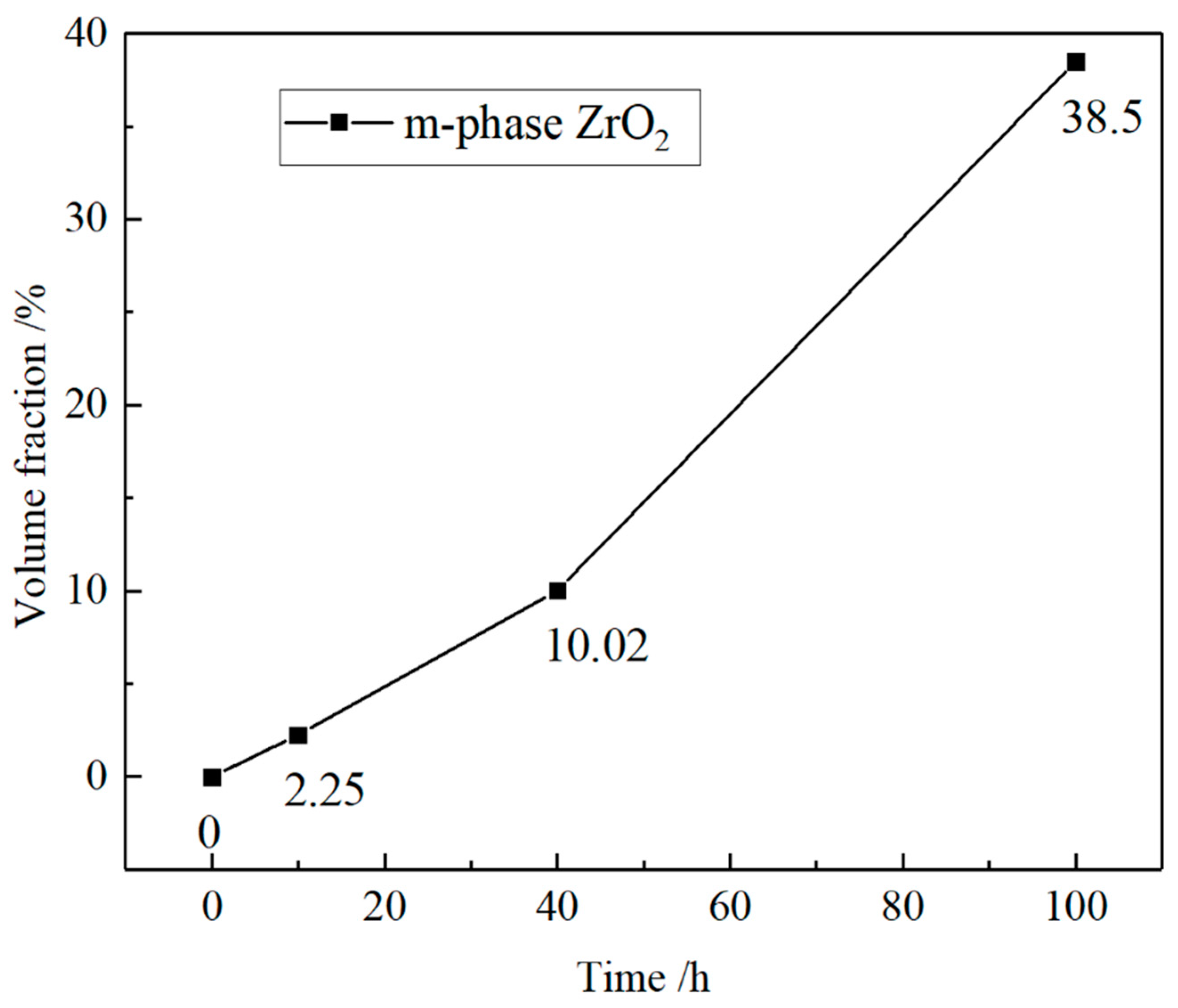
  • Intermediate stage: The molten salt reacts with Y2O3, generating corrosion products and gradually consuming Y2O3. This leads to the transformation of some t-ZrO2 into m-ZrO2. During the t → m transformation, the volume expands, leading to the formation and propagation of cracks. This allows the thermal corrosion reaction to penetrate further into the coating, thereby accelerating the thermal corrosion process.
  • Final stage: The internal stress from the t → m transformation, combined with the stresses from TGO and mismatched thermal expansion, can result in the formation of cracks between the metal matrix, bonding layer, and ceramic layer. These stresses eventually lead to coating failure and exfoliation.
In the high-temperature corrosive environment, molten Na2SO4 can be considered to contain an alkaline component (Na2O) and an acidic component (SO3), i.e.,
N a 2 S O 4 N a 2 O + S O 3
As the above reaction proceeds, the concentrations of Na2O and SO3 increase until equilibrium is reached. The equilibrium constant for the reaction can be expressed as follows:
K = C ( N a 2 O ) × C ( S O 3 ) C ( N a 2 S O 4 )
where K represents the equilibrium constant and C denotes the material concentration. Since K is related to the ambient temperature, it has a certain value. Due to the cracks and pores formed during the multi-arc ion plating process, as well as the inherent porosity of the ceramic layer, a significant amount of Na2SO4 can penetrate into the coating. When the concentration of alkaline Na2O reaches a certain level, it reacts with zirconia in the ceramic layer to form spinel, i.e.,
N a 2 O + Z r O 2 N a 2 Z r O 3
The rate of Reaction (4) is affected by the concentrations of both Na2O and Na2ZrO3. A high Na2O concentration and a fairly low Na2ZrO3 concentration is conducive to the forward reaction in Reaction (4). The concentration of Na2O is derived from Equation (3), whereas the concentration of molten salt, C(Na2SO4), basically remains constant, as do the concentrations of Na2O and SO3. The maximum Na2O concentration, determined by a small equilibrium constant K, is low, causing Reaction (4) to proceed at an extremely slow rate.
As the reaction progresses, the concentration of the corrosion product (Na2ZrO3) continuously increases, which also influences the corrosion rate. Because the amount of Na2ZrO3 is very small, it is not detected in the XRD pattern. During the initial stage of thermal corrosion, Na2ZrO3 is dissolved in the molten salt at high temperatures and later crystallizes and precipitates in the thermal barrier coating upon reaching saturation. Although Reaction (4) causes only minor damage to the thermal barrier coating, the crystallization of the corrosion product is extremely detrimental due to the negligible amount of ZrO2 participating in the reaction. However, the precipitation and growth of Na2ZrO3 in cracks and between coating layers exacerbate crack expansion and coating layer exfoliation.
When exposed to SO3 at high temperatures, Y2O3, which stabilizes t-ZrO2, also reacts to form Y2(SO4)3, as follows:
3 S O 3 + Y 2 O 3 = Y 2 ( S O 4 ) 3
As Reaction (5) proceeds, Y2O3 is continuously consumed, leading to a sustained transformation of ZrO2 from the t-phase to the m-phase. This transformation is accompanied by a 3%–5% volume expansion, which increases internal stress between the ceramic layers and causes the formation and propagation of cracks. When the volume change reaches a certain level, the coating begins to peel off. In addition, similar to the formation of Na2ZrO3, the growth of Y2(SO4)3 crystals at the cracks and between the coating layers imposes further stress on the ceramic layer.
During the preparation of thermal barrier coatings by multi-arc ion plating, metal particles are the first to fall off in a high-temperature environment. This results in the formation of cracks and pores around the exfoliated particles, which create channels for the diffusion of molten salt into the coatings. This increases the contact area between the molten salt and the ceramic layer, thereby triggering corrosion. The reaction produces Na2ZrO3 and Y2(SO4)3 crystals. These corrosion products grow within the cracks and crystallize between the coating layers, generating thermal stress due to the formation and expansion of cracks in the ceramic layer. The generation of Y2(SO4)3 crystals continuously consumes Y2O3, causing ZrO2 to undergo a t → m phase transformation. This phase transformation and the associated volume change increase the internal stress within the ceramic layer. Additionally, during thermal corrosion, a TGO layer is formed between the bonding layer and the ceramic layer due to high-temperature oxidation. At high temperatures, the mismatch in thermal expansion coefficients between NiCr and YSZ increases internal stress. Under the combined effects of various stresses, the NiCr/YSZ coating eventually deteriorates and flakes off.

5. Conclusions

A NiCr/YSZ coating was applied on a γ-TiAl surface using multi-arc ion plating technology to enhance its high-temperature performance, and the mechanisms of high-temperature oxidation and thermal corrosion were comprehensively examined. The oxidation products on the surface of the NiCr/YSZ-coated samples after 100 h of high-temperature corrosion at 850 °C in a 75% Na2SO4 + 25% NaCl solution were mainly t-ZrO2, without any phase transformation. However, at 950 °C, although the main component remained t-ZrO2, a significant portion transformed into m-ZrO2. This was because Y2O3, the stabilizer present in YSZ, reacted with Na2SO4 during thermal corrosion, continuously consuming Y2O3, which promoted the transformation from t-ZrO2 to m-ZrO2. The resultant internal stress from the volume change in the ceramic layer finally led to the formation and expansion of cracks. The NiCr/YSZ coating exhibited good thermal corrosion resistance after 100 h of corrosion at both temperatures, but the surface film layers presented varying degrees of damage. This damage included coating exfoliation at the edges and different degrees of crack expansion on the surface. The metal particles on the coating surface gradually flaked off in the high-temperature environment, affecting the thermal corrosion performance of the coatings. The thermal corrosion of barrier coatings was accompanied by high-temperature oxidation, leading to the formation of a TGO layer at the interface between the bonding layer and the ceramic layer. A continuous and dense TGO layer effectively decelerated the diffusion of molten salt and oxygen, significantly enhancing the thermal corrosion resistance of the thermal barrier coatings.

Author Contributions

Conceptualization, F.D. and Y.L.; methodology, J.C.; validation, X.W., H.S.; formal analysis, T.Z.; investigation, F.D. and Y.M.; data curation, J.Y.; writing—original draft preparation, F.D.; writing—review and editing, F.D. and Y.M.; supervision, J.C. and X.W. All authors have read and agreed to the published version of the manuscript.

Funding

This project was supported by the Natural Science Foundation of Jiangsu Province (BK20231227), the Nantong Science and Technology project (JC12022056, JCZ2023014, MSZ2023136), the Natural Science Foundation of Jiangsu Province for universities and colleges (23KJB430012, 21KJA460014).

Institutional Review Board Statement

Not applicable.

Informed Consent Statement

Not applicable.

Data Availability Statement

Data are contained within the article.

Conflicts of Interest

The authors declare that the research was conducted in the absence of any commercial or financial relationships that could be construed as a potential conflict of interest.

References

  1. Voice, W.E.; Henderson, M.; Shelton, E.F.J.; Wu, X. Gamma titanium aluminide, TNB. Intermetallics 2005, 13, 959–964. [Google Scholar] [CrossRef]
  2. Wu, X. Review of alloy and process development of TiAl alloys. Intermetallics 2006, 14, 1114–1122. [Google Scholar] [CrossRef]
  3. Salehnasab, B.; Poursaeidi, E.; Mortazavi, S.A.; Farokhian, G.H. Hot corrosion failure in the first stage nozzle of a gas turbine engine. Eng. Fail. Anal. 2016, 60, 316–325. [Google Scholar] [CrossRef]
  4. Garip, Y.; Ozdemir, O. Comparative study of the oxidation and hot corrosion behaviors of TiAl-Cr intermetallic alloy produced by electric current activated sintering. J. Alloys Compd. 2019, 780, 364–377. [Google Scholar] [CrossRef]
  5. Jude, S.A.A.; Jappes Jtwinowlin Adamkhan, M. Thermal barrier coatings for high-temperature application on superalloy substrates—A review. Mater. Today Proc. 2022, 60, 1670–1675. [Google Scholar] [CrossRef]
  6. Anirudh, S.; Satheesh, K.; Balasubramanian, K.; Praveen, K.B. Probing into atomically thin layered nano-materials protective coating for aerospace and strategic defence application—A review. J. Alloys Compd. 2023, 968, 172203. [Google Scholar]
  7. Tian, S.; Zhang, Y.; Jiang, H.; Zhang, S.; Zeng, S.; Song, D.; Li Chong Liao, Z.; Chen, Y.; Zhang, Y. Effect of micron/nano Nb particles on high-temperature oxidation behavior of TiAl alloy/thermal barrier coating system. Surf. Coat. Technol. 2024, 492, 131206. [Google Scholar] [CrossRef]
  8. Taylor, R.; Brandon, J.R.; Morrell, P. Microstructure, composition and property relationships of plasma-sprayed thermal barrier coatings. Surf. Coat. Technol. 1992, 50, 141–149. [Google Scholar] [CrossRef]
  9. Voyer, J.; Gitzhofer, F.; Boulos, M.I. Study of the Performance of TBC under Thermal Cycling Conditions using an Acoustic Emission Rig. J. Therm. Spray Technol. 1998, 7, 181–190. [Google Scholar] [CrossRef]
  10. Troczynski, T.; Yang, Q.; John, G. Post-deposition treatment of zirconia thermal barrier coatings using sol-gel alumina. J. Therm. Spray Technol. 1999, 8, 229–234. [Google Scholar] [CrossRef]
  11. Schilbe, J.E. Substrate alloy element diffusion in thermal barrier coatings. Surf. Coat. Technol. 2000, 133–134, 35–39. [Google Scholar] [CrossRef]
  12. Zhou, S.; Xiong, Z.; Dai, X.; Liu, J.; Zhang, T.; Wang, C. Microstructure and oxidation resistance of cryomilled NiCrAlY coating by laser induction hybrid rapid cladding. Surf. Coat. Technol. 2014, 258, 943–949. [Google Scholar] [CrossRef]
  13. Wu, Y.N.; Zhang, G.; Feng, Z.C.; Zhang, B.C.; Liu, F.J. Oxidation behavior of laser remelted plasma sprayed NiCrAlY and NiCrAlY-Al2O3 coatings. Surf. Coat. Technol. 2001, 138, 56–60. [Google Scholar] [CrossRef]
  14. Ansari, M.; Shoja-Razavi, R.; Barekat, M.; Man, H.C. High-temperature oxidation behavior of laser-aided additively manufactured NiCrAlY coating. Corros. Sci. 2017, 118, 168–177. [Google Scholar] [CrossRef]
  15. Peng Bin Xu, Y.X.; Wang, Q. High-temperature structural evolution and mechanical properties of oxygen-containing NiCrAlY coatings. Appl. Surf. Sci. 2024, 671, 160745. [Google Scholar] [CrossRef]
  16. Gavahian, J.M.; Shoja, R.R.; Valefi, Z.; Hamed, N.; Taghi-Ramezani, S. Evaluating laser surface melting of NiCrAlY-APS coating and its effect on high-temperature oxidation behavior of NiCrAlY/YSZ thermal barrier coating before and after surface melting. Heliyon 2024, 12, 23094. [Google Scholar] [CrossRef]
  17. Senturk, B.S.; Garces, H.F.; Ortiz, A.L.; Dwivedi, G.; Sampath, S.; Padture, N.P. CMAS-resistant plasma sprayed thermal barrier coatings based on Y2O3-Stabilized ZrO2 with Al3+ and Ti4+ solute additions. J. Therm. Spray Technol. 2014, 23, 708–715. [Google Scholar] [CrossRef]
  18. Chen, S.; Xiang, J.; Huang, J.; Zhao, X. Microstructures and properties of double-ceramic-layer thermal barrier coatings of La2(Zr0.7Ce 0.3)2O7/8YSZ made by atmospheric plasma spraying. Appl. Surf. Sci. 2015, 340, 173–181. [Google Scholar] [CrossRef]
  19. Bengtsson, P.; Johannesson, T. Characterization of microstructural defects in plasma-sprayed thermal barrier coatings. J. Therm. Spray Technol. 1995, 4, 245–251. [Google Scholar] [CrossRef]
  20. Di Girolamo, G.; Blasi, C.; Brentari, A.; Schioppa, M. Microstructural, mechanical and thermal characteristics of zirconia-based thermal barrier coatings deposited by plasma spraying. Ceram. Int. 2015, 41, 11776–11785. [Google Scholar] [CrossRef]
  21. Feuerstein, A.; Knapp, J.; Taylor, T.; Ashary, A.; Bolcavage, A.; Hitchman, N. Technical and Economical Aspects of Current Thermal Barrier Coating Systems for Gas Turbine Engines by Thermal Spray and EBPVD: A Review. J. Therm. Spray Technol. 2008, 17, 199–213. [Google Scholar] [CrossRef]
  22. Tadeusz, B.; Tadeusz, W. Surface Engineering of Metals; Taylor and Francis, CRC Press: Warsaw, Poland, 2010. [Google Scholar]
  23. Khono, M.; Ikenaga, M.; Ichimura, H. Properties and Industrial Application of Arc Ion Plating Films. J. Surf. Finish. Soc. Jpn. 2011, 44, 708–714. [Google Scholar] [CrossRef]
  24. Jiang, X.F.; Liu, Q.C.; Wang, H.B. Technology and Application of Multi-Arc Ion Plating. J. Chongqing Univ. 2006, 29, 52–55. [Google Scholar]
  25. Yan, D.; Xu, W.; Li, J.; Ji, L.; Liu, X.; Shi, L.; Sun, C.; Li, H. Effect of nitrogen/argon ratios on structures and properties of high-entropy (ZrTiNbV)N nitride films by multi-arc ion plating. Vacuum 2024, 225, 113173. [Google Scholar] [CrossRef]
  26. Shi, C.M.; Wang, T.G.; Pei, Z.L.; Gong, J.; Sun, C. Effects of the Thickness Ratio of CrN vs Cr2O3 Layer on the Properties of Double-layered CrN/Cr2O3 Coatings Deposited by Arc Ion Plating. J. Mater. Sci. Technol. 2014, 30, 473–479. [Google Scholar] [CrossRef]
  27. Yang, Z.; Zhang, J.; Luo, C.; Yu, C.; Li, M.; Han, W. Effect of pre-oxidation and sea salt on the hot corrosion behavior of MCrAlY coatings and AlSi coatings. Surf. Coat. Technol. 2024, 477, 130354. [Google Scholar] [CrossRef]
  28. Tian, C.; Yang, B.; He, J.; Wang, H.; Wang, Z.; Wang, G.; Fu, D. Structure and tribological properties of CrTiAlN coatings deposited by multi-arc ion plating. Plasma Sci. Technol. 2011, 13, 55–60. [Google Scholar] [CrossRef]
  29. Pflumm, R.; Friedle, S.; Schütze, M. Oxidation protection of γ-TiAl-based alloys—A review. Intermetallics 2014, 56, 1–14. [Google Scholar] [CrossRef]
  30. Wang, H.; Zhang, X.; Xu, Z.; Wang, H.; Zhu, C. Hot corrosion behaviour of Al-Si coating in mixed sulphate at 1150 °C. Corros. Sci. 2019, 147, 313–320. [Google Scholar] [CrossRef]
  31. Cai, J.; Gao, C.; Lv, P.; Zhang, C.; Guan, Q.; Lu, J.; Xu, X. Hot corrosion behaviour of thermally sprayed CoCrAlY coating irradiated by high-current pulsed electron beam. J. Alloys Compd. 2019, 784, 1221–1233. [Google Scholar] [CrossRef]
  32. Habibi, M.H.; Yang, S.; Guo, S.M. Phase stability and hot corrosion behavior of ZrO2-Ta2O5 compound in Na2SO4-V2O5 mixtures at elevated temperatures. Ceram. Int. 2014, 40, 4077–4083. [Google Scholar] [CrossRef]
  33. Habibi, M.H.; Wang, L.; Liang, J.; Guo, S.M. An investigation on hot corrosion behavior of YSZ-Ta2O5 in Na2SO4+V2O5 salt at 1100 °C. Corros. Sci. 2013, 75, 409–414. [Google Scholar] [CrossRef]
  34. Fan, Z.; Wang, K.; Dong, X.; Wang, R.; Duan, W.; Mei, X.; Wang, W.; Cui, J.; Zhang, S.; Xu, C. The role of the surface morphology and segmented cracks on the damage forms of laser re-melted thermal barrier coatings in presence of a molten salt (Na2SO4 + V2O5). Corros. Sci. 2017, 115, 56–67. [Google Scholar] [CrossRef]
  35. Habibi, M.H.; Guo, S.M. The hot corrosion behavior of plasma sprayed zirconia coatings stabilized with yttria, ceria, and titania in sodium sulfate and vanadium oxide. Mater. Corros. 2015, 66, 270–277. [Google Scholar] [CrossRef]
  36. Zhou, C.H.; Zhang, Z.Y.; Zhang, Q.M.; Li, Y. Comparison of the hot corrosion of nanostructured and microstructured thermal barrier coatings. Mater. Corros. 2014, 65, 613–618. [Google Scholar] [CrossRef]
  37. Loghman-Estarki, M.R.; Nejati, M.; Edris, H.; Shoja Razavi, R.; Jamali, H.; Pakseresht, A.H. Evaluation of hot corrosion behavior of plasma sprayed scandia and yttria co-stabilized nanostructured thermal barrier coatings in the presence of molten sulfate and vanadate salt. J. Eur. Ceram. Soc. 2015, 35, 693–702. [Google Scholar] [CrossRef]
  38. Sun, Y.; Miao, Q.; Sun, S.; Liang, W.; Ding, Z.; Niu, J.; Jia, F.; Xu, J.; Gao, J. High-Temperature Hot Corrosion Resistance of CrAl/NiCoCrAlY/AlSiY Gradient Composite Coating on TiAl Alloy. Coatings 2024, 14, 1067. [Google Scholar] [CrossRef]
  39. Keyvani, A.; Saremi, M.; Sohi, M.H. An investigation on oxidation, hot corrosion and mechanical properties of plasma-sprayed conventional and nanostructured YSZ coatings. Surf. Coat. Technol. 2011, 206, 208–216. [Google Scholar] [CrossRef]
  40. Tsai, P.C.; Lee, J.H.; Chang, C.L. Improving the erosion resistance of plasma-sprayed zirconia thermal barrier coatings by laser glazing. Surf. Coat. Technol. 2007, 202, 719–724. [Google Scholar] [CrossRef]
Figure 1. SEM image (a) and the EDS analysis results (b) of the NiCr/YSZ coating.
Coatings 14 01150 g001
Figure 2. Cross-sectional microstructure (a) and element distribution (b) of the NiCr/YSZ coating.
Coatings 14 01150 g002
Figure 3. XRD pattern of the NiCr/YSZ coating.
Coatings 14 01150 g003
Figure 4. Thermal corrosion kinetics curve of the γ-TiAl substrate and NiCr/YSZ coating at 850 °C.
Coatings 14 01150 g004
Figure 5. Microstructure of NiCr/YSZ-coated samples during thermal corrosion at 850 °C: (a) 0 h, (b) 10 h, (c) 40 h, and (d) 100 h.
Coatings 14 01150 g005
Figure 6. Cross-sectional micrograph (a) and EDS analysis (b) of the NiCr/YSZ coating after 100 h of thermal corrosion at 850 °C.
Coatings 14 01150 g006
Figure 7. XRD pattern of the NiCr/YSZ coating after 100 h of thermal corrosion at 850 °C.
Coatings 14 01150 g007
Figure 8. Thermal corrosion kinetics curve of the γ-TiAl substrate and NiCr/YSZ coating at 950 °C.
Coatings 14 01150 g008
Figure 9. Surface morphology of the NiCr/YSZ coating during thermal corrosion at 950 °C: (a) 10 h, (b) 40 h, and (c) 100 h.
Coatings 14 01150 g009
Figure 10. Cross-sectional (a) and EDS analysis (b) of the NiCr/YSZ coating after 100 h of thermal corrosion at 950 °C.
Coatings 14 01150 g010
Figure 11. XRD pattern of the NiCr/YSZ coating during thermal corrosion at 950 °C.
Coatings 14 01150 g011
Figure 12. Line chart for the volume fraction of m-phase ZrO2.
Coatings 14 01150 g012
Table 1. Chemical composition of γ-TiAl alloy (wt. %).
TiAlVNbCrNCO
50.6446.501.501.000.200.050.100.01
Disclaimer/Publisher’s Note: The statements, opinions and data contained in all publications are solely those of the individual author(s) and contributor(s) and not of MDPI and/or the editor(s). MDPI and/or the editor(s) disclaim responsibility for any injury to people or property resulting from any ideas, methods, instructions or products referred to in the content.

