Article

The Enhanced Electrochemical Properties of Lithium-Rich Manganese-Based Cathode Materials via Mg-Al Co-Doping

1
School of Materials Science and Engineering, Guilin University of Electronic Technology, Guilin 541000, China
2
Intelligent Manufacturing Institute, Guangdong Technology College, Zhaoqing 526100, China
3
Institute of New Functional Materials, Guangxi Institute of Industrial Technology, Nanning 530200, China
*
Authors to whom correspondence should be addressed.
Coatings 2025, 15(1), 3; https://doi.org/10.3390/coatings15010003
Submission received: 9 November 2024 / Revised: 12 December 2024 / Accepted: 18 December 2024 / Published: 24 December 2024

Abstract

:
Due to the advantages of high capacity, low working voltage, and low cost, lithium-rich manganese-based material (LMR) is the most promising cathode material for lithium-ion batteries; however, the poor cycling life, poor rate performance, and low initial Coulombic efficiency severely restrict its practical utility. In this work, the precursor Mn2/3Ni1/6Co1/6CO3 was obtained by the continuous co-precipitation method, and on this basis, different doping levels of aluminum–magnesium were applied to modify the electrode materials by high-temperature sintering. The first discharge capacity can reach 295.3 mAh·g−1 for the LMR material of Li1.40(Mn0.666Ni0.162Co0.162Mg0.005Al0.005)O2. The Coulombic efficiency is 83.8%, and the capacity retention rate remains at 84.4% after 300 cycles at a current density of 1 C for the Mg-Al co-doped LMR material, superior to the unmodified sample. The improved electrochemical performance is attributed to the increased oxygen vacancy and enlarged lithium layer spacing after trace magnesium–aluminum co-doping, enhancing the lithium-ion diffusion and effectively mitigating voltage degradation during cycling. Thus, magnesium–aluminum doping modification emerges as a promising method to improve the electrochemical performance of lithium-rich manganese-based cathode materials.

1. Introduction

Resource consumption and environmental pollution are hindering social and economic progress. The development of renewable energy technologies can alleviate this situation to some extent [1]. Green and low-carbon energy sources such as solar energy, wind energy, and tidal energy have periodic and fluctuating power generation processes under environmental constraints. When used in conjunction with energy storage stations, the renewable energy can achieve the maximum efficiency. Lithium-ion batteries are considered one of the most promising energy storage solutions due to their long lifespan, high energy density, and no memory effect [2,3]. As a key component of lithium-ion batteries, cathode materials play a decisive role in their energy density, cycle life, and cost; therefore, it is crucial to obtain advanced cathode materials that are more economically applicable, have higher capacity, and are more environmentally friendly [4,5].
The lithium-rich manganese-based material xLi2MnO3·(1-x) LiMO2 (LMR) has attracted much attention due to its high specific discharge capacity (>250 mAh·g−1), high operating voltage (>3.7 V), high energy density, and environmental friendliness; however, the low coulombic efficiency, poor rate performance and poor cycle stability restrict its further promotion and application, due to the structure evolution and transition metal dissolution [6,7]. Thus, an efficient way to raise the electrochemical performance of lithium-rich manganese-based material is required.
Surface modification on the material can form a protective layer to enhance the electrochemical performance of LMR. Ran et al. [8] used low-temperature hydrolysis to encapsulate TiO2 on the surface of the Li1.2Mn0.54Ni0.13Co0.13O2 cathode material. The initial coulombic efficiency increased from 76.1% to 82.4% and the modified sample provided a capacity of 130.3 mAh·g−1 at 5 C after TiO2 coating. Moreover, TiO2-modified samples can provide higher specific capacity and cycling retention rates, proving that TiO2 coating can prevent the active material from being corroded by the electrolyte.
Yu et al. [9] used atomic layer deposition to deposit a composite capsulation of Al2O3 and AlF3 on the electrode surface of the cathode material Li1.2Mn0.54Ni0.13Co0.13O2. After 200 cycles, the capacity retention rate of the sample with the composite coating was 84%, which was much higher than that of the original sample. This composite capsulation suppressed side reactions between the electrolyte and the electrode. Huang et al. [10] prepared Li1.17Ni0.2Co0.05Mn0.58O2 cathode material with LiAlO2 coating by sol-gel method; this can provide a specific discharge capacity of 268.2 and 191.9 mAh·g−1 at 0.1 C and 1 C. LiAlO2 coating can significantly inhibit the increase in charge transfer resistance and the structural change in the material during cycling. Element doping is another effective way to stabilize the material structure. Zhao et al. [11] synthesized zinc-doped Li1.2Mn0.54Ni0.13Co0.13O2 materials and found that zinc doping significantly improved the cycling performance, which was attributed to the reduced charge transfer resistance and increased exchange current density. He et al. [12] introduced sodium ions into Li1.2Mn0.54Ni0.13Co0.13O2 through the polymer polymerization method, which can provide an initial Coulombic efficiency of 87% and a capacity retention rate of 89% after 100 cycles.
Among the doped elements, Mg and Al have received widespread attention due to their abundant reserves, non-toxicity, low cost, and relatively small atomic mass. T. Weigel et al. [13] doped LiNi0.8Co0.1Mn0.1O2 material with magnesium and observed that the volume change in the material’s structure during lithium deintercalation was small, indicating that the structure was subjected to low stress and a low degree of cracking, which can effectively improve cycling stability. Huang et al. [14] synthesized magnesium-doped Li1.2Mn0.54Ni0.13Co0.13O2 through the spray-drying method. The cathode material has a more stable lattice structure and higher reversibility after magnesium ions replace some lithium ions, forming Li-O-Mg with a stronger bond energy. Guo et al. [15] synthesized Li1.14 (Ni0.136Co0.10Al0.03Mn0.544) O2 oxide with the excellent retention rate of 94.7% after 100 cycles and found that aluminum doping can enhance the electrode interface. Shi et al. [16] doped Li1.2Mn0.54Ni0.13Co0.13O2 with aluminum and found that it achieved a specific discharge capacity of 271.0 mAh·g−1 at 0.1 C and a capacity retention rate of 97.3% after 100 cycles at 0.5 C. Based on these reported results, it can be found that magnesium ion or aluminum ion doping can improve the electrochemical performance and enhance structural stability of lithium–manganese-based cathode materials. Therefore, the use of dual cation co-doping is an interesting attempt for improving the electrochemical performance of lithium–manganese-based cathode materials. In this work, Mn-rich carbonate precursors (Mn2/3Ni1/6Co1/6CO3) were obtained by the continuous co-precipitation method, and different doping levels of aluminum–magnesium were applied to modify the electrode materials by high-temperature sintering. The introduction of Mg and Al cations lead to significant improvements in the material’s structural and electrochemical properties. Specifically, Mg-Al co-doping enhances the layered structure, reduces cation mixing, and increases the layer spacing, which collectively facilitates lithium-ion transport and improves the electrochemical performance. This approach provides a promising direction for advancing high-performance and long-lasting energy storage systems, particularly for renewable energy applications.

2. Experimental Section

2.1. Materials Preparation

The precursors were prepared through continuous coprecipitation. Manganese sulfate monohydrate, nickel sulfate hexahydrate, and cobalt sulfate heptahydrate were weighed according to the stoichiometric ratio (Mn:Ni:Co = 1:4:1) and dissolved in deionized water to prepare a salt solution (2 mol·L−1) to provide metal ions in the precursors. Sodium carbonate solution was chosen as the precipitant, with a molar concentration of 2 mol·L−1. The metal salt solution and precipitant were continuously added to the coprecipitation reactor using a metering pump at a flow rate of 60 ml·h−1, along with an adequate quantity of ammonia water as an agent for complexing. The reaction was maintained at a temperature of approximately 55 °C, a reaction pH of 7.5, and a stirring speed of 1000 rpm. After the reaction was completed, the mixture was allowed to mature for a certain period before being cleaned, filtered, and dried to produce precursor materials.
Li-rich manganese-based cathode materials were produced by sintering lithium carbonate at a high temperature. Following a molar ratio of lithium ions, provided by the lithium source to metal ions, provided by a precursor of lithium carbonate at 1.4:1, lithium carbonate and the corresponding precursor were weighed, evenly mixed with a mortar, pre-sintered at 500 °C for 5 h, and then sintered at 850 °C for 12 h. The original lithium-rich manganese-based cathode material Li1.40(Mn0.666Ni0.167Co0.167)O2 was calculated based on the amount of lithium added and named LRMO. Figure 1 depicts the adjustment of the doping elements, with Mg replacing Ni and Al replacing Co.
The metal salt, with a stoichiometric ratio of Mn:Ni:Co:Mg:Al = 144:35:35:1:1, was prepared into a 2 mol·L−1 solution using the same procedure as LRMO preparation but with a different ratio of metal ions. Mg and Al, prepared in this manner, were co-doped into Ni and Co sites. (Mn0.666Ni0.162Co0.162Mg0.005Al0.005)O2 was designated as LRMO&Mgal-1. Maintaining a stoichiometric ratio of Mn:Ni:Co:Mg:Al = 144:33:33:3, the resulting lithium-rich manganese-based cathode material Li1.40(Mn0.666Ni0.153Co0.153Mg0.014Al0.014)O2, co-doped with Mg and Al at Ni and Co sites, was designated as LRMO&Mgal-2.

2.2. Phase Characterization

Using an X-ray diffractometer (XRD, Rigaku D/max2550 VB, Rigaku, Tokyo, Japan, Cu-Kα as radiation source, λ = 0.154 nm, and the measuring range of 2θ was 10–120°) to analyze the structure of the LRMO, LRMO&Mgal-1, and LRMO&Mgal-2 Li-rich manganese-based cathode materials, the structure was refined by Rietveld method with GSAS I software (GSAS I, open source software developed by Argonne National Laboratory, Lemont, IL, USA). The morphology of the sample surface was analyzed using a scanning electron microscope (SEM, Quanta 450 FEG, FEI, Hillsboro, OR, USA), and the information on element composition, distribution, and content on the material surface was analyzed using an X-ray energy dispersive spectrometer (EDS, Oxford Instruments, Oxfordshire, England). We used a transmission electron microscope (HRTEM, Hillsborough, OR, USA) to examine the primary particle size, crystal characteristics, and surface coating of the material. Utilizing the Thermo Scientific K-Alpha equipment (Thermo Scientific, Waltham, MA, USA), X-ray photoelectron spectroscopy (XPS, ESCALAB250xi, Thermo Scientific, Waltham, MA, USA) was applied to analyze the distribution of valence states and elemental composition on the material’s surface.

2.3. Electrochemical Performance Test

The electrochemical performance of the prepared samples was assessed using a CR2032 button cell. Following a mass ratio of 8:1:1, the lithium-rich manganese-based cathode material, Super P conductive agent, and polyvinylidene difluoride (PVDF) binder were individually weighed using a balance. An appropriate amount of N-methyl-2pyrrolidone (NMP) was employed as a solvent to create a positive pole piece. Subsequently, a half-cell was assembled with a lithium metal wafer serving as the negative electrode within a glove box filled with argon. Charging and discharging of the battery were conducted using a tester from Landian Company (Cheyenne, WY, USA), with a voltage range of 2.0–4.8 V, designated as 250 mAh·g−1 (1 C) amid the charging and discharging process. Typically, the battery underwent initial activation by charging and discharging at a current of 0.1 C. The cyclic voltametric curve (CV) of the battery was measured using the PMC 2000A electrochemical workstation from AMTEK Company (Berwyn, PA, USA), scanning at a rate of 0.1 mV·s−1 within the voltage range of 2.0 V to 5.0 V. The chemical alternating-current impedance test was performed with an amplitude of 5 mV and testing parameters spanning 0.01 Hz to 100 KHz. The completed button cell was tested by calculating the diffusion velocity of lithium ions and then analyzing the kinetics using the BT-2000 electrochemical workstation from AIRBIN Company (College Station, TX, USA).

3. Results and Discussion

3.1. Structure and Composition Characterization of Mg-Al Co-Doped LMR

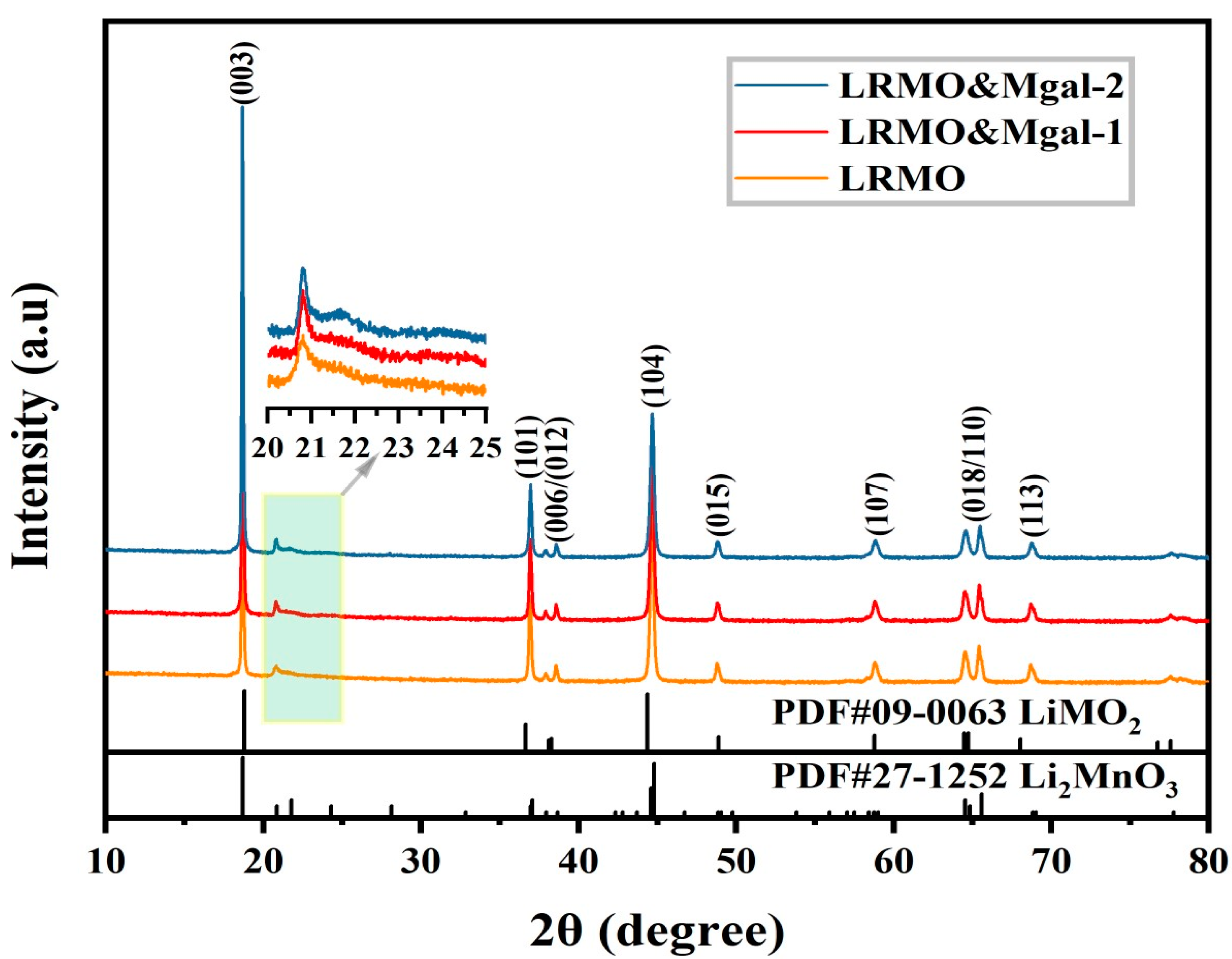
XRD was utilized to acquire structural information for LRMO, LRMO&Mgal-1, and LRMO&Mgal-2. As depicted in Figure 2, all three samples exhibited similar XRD patterns, and LiTMO2 (space group R-3m) could be indexed. A faint diffraction peak corresponding to the monoclinic Li2MnO3 (space group C2/m) is observed when 2θ ranges between 20° and 25° [17,18]. The noticeable separation of the (018)/(110) and (006)/(012) diffraction peaks indicates that the Mg-Al-doped samples still retain a well-defined layered structure [19]. The ratio of I(003)/I(104) is calculated to gauge the mixing degree of Li+/Ni2+ cations in the layered structure of the anode oxide. A larger ratio suggests a lower degree of mixing of lithium and nickel in the material, contributing to greater stability during long-term cycling processes [12]. All three samples exhibit I(003)/I(104) ratios exceeding 1.2. The results indicate that the layered structures of the three materials are well-ordered, with LRMO measuring 2.6624, LRMO&Mgal-1 measuring 2.7191, and LRMO&Mgal-2 measuring 2.7393. This suggests that the Mg-al co-doping method may have successfully inhibited the phenomenon of mixed layered cations.
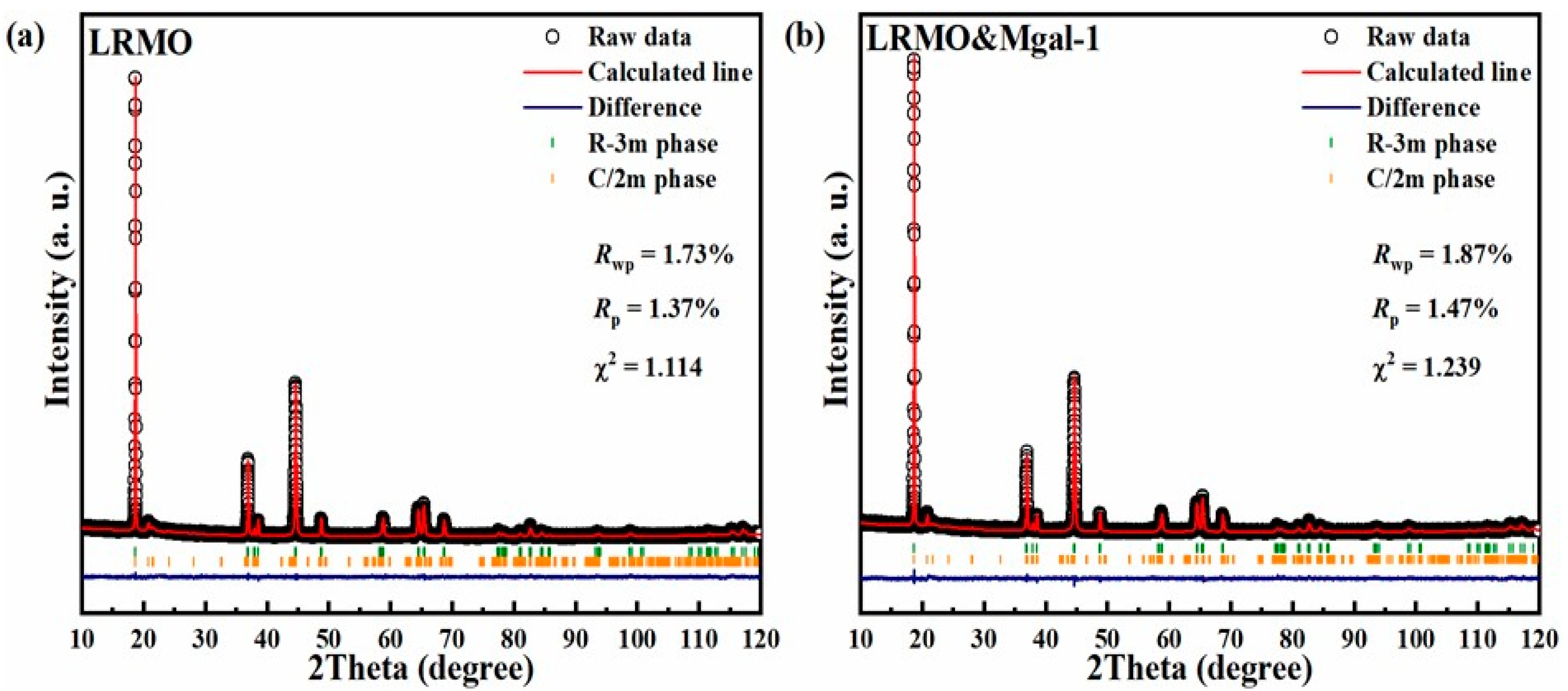
The LRMO and LRMO&Mgal-1 materials were refined using GSAS I software [20], and the refined results are shown in Figure 3a,b. Table 1 shows the lattice parameters and fitting data. In comparison to the undoped samples, the lattice parameters of the samples co-doped with Mg and Al show a slight increase, which is related with the trace amount of Mg-Al co-doping. The c/a value also increases from 4.9910 to 4.9930, which proves beneficial in enhancing the interlayer spacing of the materials after Mg-Al co-doping.
SEM images of the materials are shown in Figure 4a–c. The electrode material comprises spherical secondary particles assembled from primary particles, and the sphericity of the sample becomes irregular after magnesium–aluminum doping. It can be observed from Figure 4d–f that there are pores on the surface of the material, which are related to CO2 escaping during calcination [21]. The cathode material co-doped with magnesium and aluminum exhibits a denser surface morphology after sintering, which can provide a better protective barrier toward electrolytes. This compact surface effectively resists surface erosion caused by by-products like hydrofluoric (HF) during cycling, and minimizes the interaction between electrolyte by-products and secondary particles.
The TEM images of the LRMO&Mgal-1 sample are shown in Figure 5a,b to illustrate the phase structure information of the material. In the selected area, the lattice fringe spacing is measured and treated with Fast Fourier Transform (FFT), revealing a clear lattice stripe spacing of approximately 0.479 nm. The lattice stripe spacing is determined to the (003) crystal plane corresponding to the layered LiMO2 by combining the diffraction spots, which indicates the layered structure is well developed after co-doping with Mg and Al. Surface analysis by EDS (Figure 5c–h) demonstrated an even distribution of the main elements Mn, Co, and Ni, along with the doped elements Mg and Al, which is advantageous for the enhanced electrochemical performance.
The XPS analysis was used to study the elemental composition and chemical valence states of the LRMO and LRMO&Mgal-1 materials. In the XPS spectrum of Ni 2P (Figure 6a), the main peak of Ni 2p3/2 in the LRMO material is located at approximately 854.8 eV. Upon doping with magnesium and aluminum, the primary peak of Ni 2p3/2 shifted toward a higher binding energy, reaching 855.4 eV. This shift may indicate a reduction in the ratio of Ni2+ with an increased ratio of Ni3+. The energies at 854.4 eV and 855.5 eV are assigned to Ni2+ and Ni3+, respectively [22]. Figure 6e confirms a decrease in the content ratio of Ni2+ from 67.18% to 60.12%, accompanied by an increase in the content ratio of Ni3+ from 32.82% to 38.86%.
In Figure 6b, Co 2p3/2 and Co 2p1/2 are identified at +779.9 eV and +795.1 eV, respectively, indicating two characteristic peaks of Co3+ and Co2+ [23]. Moving on to Figure 6c, the XPS spectrum of O 1s reveals peaks at 529.7, 531.4, and 534.1 eV, associated with lattice oxygen, oxygen vacancy, and chemisorbed oxygen, respectively. The peak area ratio analysis in Figure 6 illustrates that LRMO&Mgal-1 exhibits a higher proportion of oxygen vacancies. It has been reported that oxygen vacancies can contribute to the ion diffusion in the bulk and significantly inhibit O2 release from the surface by theoretical calculations and experimental characterizations, which is favorable for long lifespans and voltage retention [24,25]. Moreover, the increased oxygen vacancy content enhances the reversibility of transition metal ion redox during charging and discharging [26].
The change in the chemical valence state of Mn is assessed by ΔE between 3s peaks of Mn [27]. Utilizing the formula (AOS = 8.956–1.126ΔE), the average oxidation state (AOS) of Mn is calculated [28]. From Figure 6e, LRMO and LRMO&Mgal-1 exhibit ΔE values of 4.76 eV and 4.59 eV, respectively, resulting in AOS values of +3.60 and +3.78. In the Mg-Al doped material, the AOS of Mn is higher, leading to an increase in Mn4+ content and a decrease in Mn3+ content, effectively suppressing the Jahn–Teller effect [29].

3.2. Electrochemical Properties of LMR-Based Materials

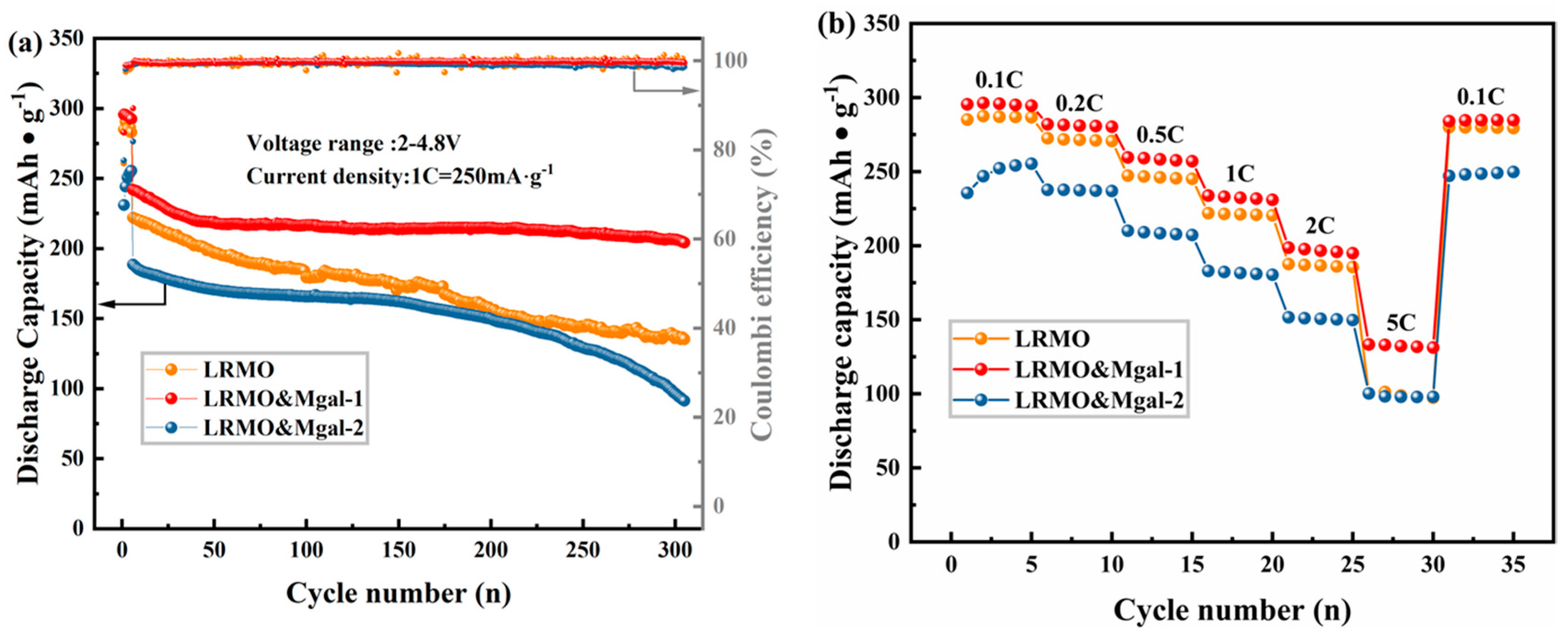
As shown in Figure 7a, LRMO, LRMO&Mgal-1, and LRMO&Mgal-2 were activated at 0.1 C and then charged and discharged for 300 cycles at 1 C current density. At 1 C current density, the first-cycle specific discharge capacities of the materials are 222.0, 241.8, and 188.4 mAh·g−1, respectively. After 300 cycles, the sample discharge retention rates are 60.9%, 84.4%, and 48.4%, respectively, indicating that the LRMO&Mgal-1 material shows excellent cycling performance of all the samples. The cyclability of the single-Mg doped sample at 1 C current density is depicted in Figure S1, and the discharge retention rate is 81.82% for the single-Mg doped sample, which is superior to the original sample but remains inferior to the LRMO&Mgal-1 sample. Two distinct phases of capacity attenuation related to the charge–discharge cycle can be observed. The charge–discharge cycle retention rate was 89.7% for the first 50 cycles, with a specific discharge capacity of 217.4 mAh·g−1. Impressively, the cycle retention rate remained high at 93.9% from the 51st cycle to the 300th cycle.
Mg2+ can stabilize the column in layered materials [30] and prevent the cathode material transitioning from a layered structure to a spinel structure with higher dissociation energy of the Mg-O bond [31,32]. Al3+ can act as a positive charge center to promote the diffusion of Li+, facilitating the development of a thin CEI layer on the surface, preventing the structure’s phase transition [33,34,35,36]. Therefore, the synergistic effect of Mg-Al co-doping contributes to cycling performance and structural stability [37]. In addition, the improved cycling life is attributed to the increased oxygen vacancy and the increased ratio of Mn4+ after Mg-Al modification [26], consistent with the valence state analysis confirmed by XPS.
Figure 7b presents the rate performance of the samples. It is evident that the LRMO&Mgal-1 material exhibits a higher specific discharge capacity at various rates than the untreated one. The specific discharge capacity is 295.4, 281.9, 259.6, 233.8, 198.6, 133.3, and 284.0 mAh·g−1 at current densities of 0.1 C, 0.2 C, 0.5 C, 1 C, 2 C, 5 C, and 0.1 C, respectively. Especially, at a current density of 5 C, the specific discharge capacity exhibits significant improvement (133.3 mAh·g−1 vs. 100.2 mAh·g−1). For the single-Mg doped sample, the discharge capacity at 5 C is 100.6 mAh·g−1 (depicted in Figure S2), which is close to the original sample. The improvement in the rate capability is not obvious for the single-Mg doped sample. The co-doping of Mg2+ and Al3+ increases the interlayer spacing of the transition metal layers, thereby reducing the barrier for Li+ intercalation and deintercalation and increasing the diffusion rate of lithium ions [37]. Oxygen vacancies after Mg-Al doping also help to enhance charge transfer, thus improving rate performance [24]. However, at a current density of 0.1 C, the specific discharge capacity of LRMO&Mgal-2 is only 230 mAh·g−1 at the first cycle, much lower than the LRMO&Mgal-1. It shows a gradually increasing trend in the first five cycles but it is still far lower than LRMO&Mgal-2 in the same cycle; this suggests that LRMO&Mgal-2 requires an activation process, which is not conducive to the electrochemical performance when there is too much Mg-Al doping.
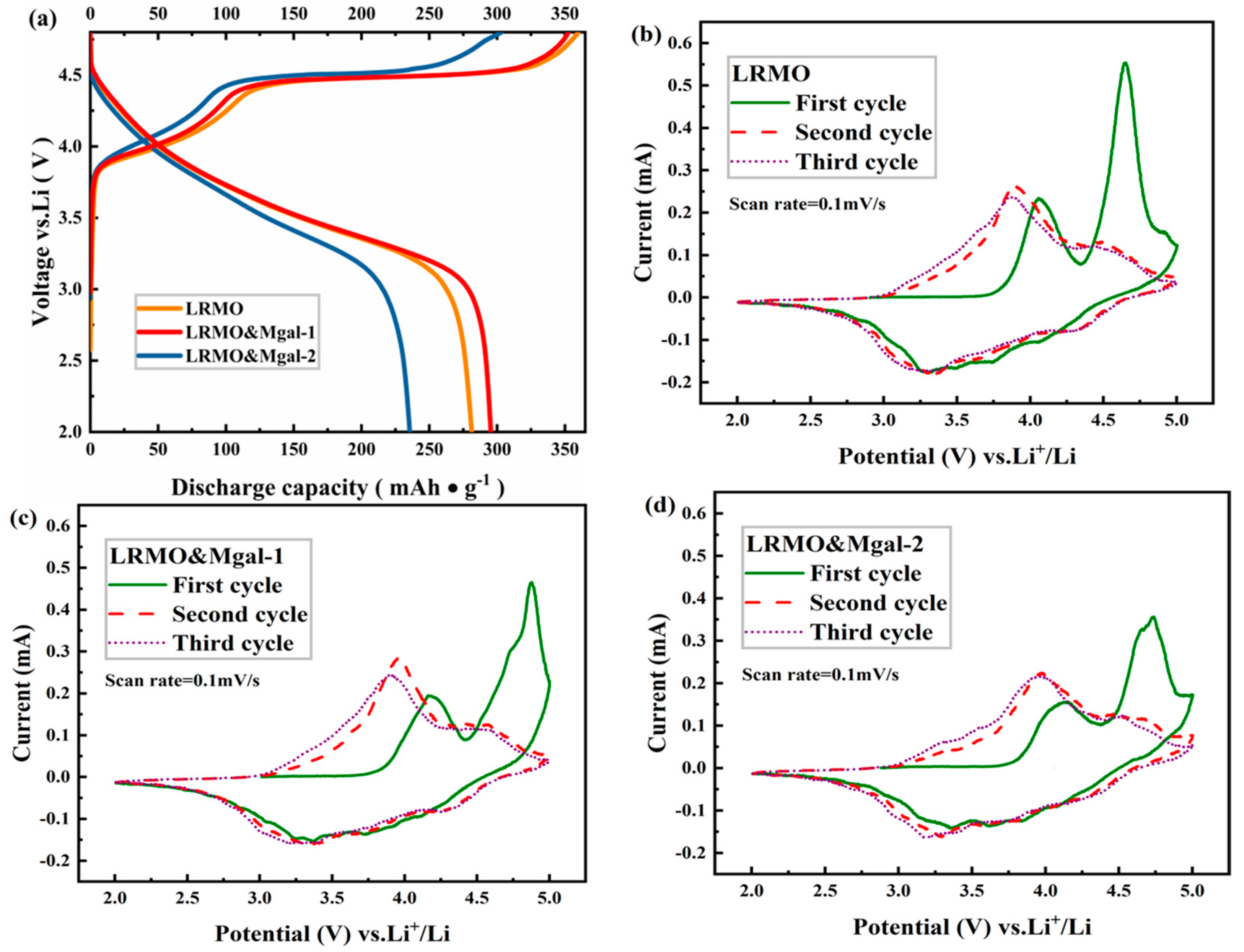
The initial charge/discharge curves at 0.1 C current density are illustrated for the LRMO, LRMO&Mgal-1, and LRMO&Mgal-2 samples in Figure 8a. Two distinct voltage plateaus are observed. The first plateau occurs during the charging voltage ramp before 4.5 V, accompanying the process of Li+ detachment from the layer structure, which is associated with the oxidation reactions of Ni2+/Ni3+ and Co2+/Co3+ to higher valence states (Ni4+ and Co4+) [38]. The subsequent voltage plateau during charging to 4.8 V is linked to the loss of lattice oxygen in the Li2MnO3 phase [39]. LRMO&Mgal-1 materials exhibited first charging and discharging specific capacities of 352.5 and 295.3 mAh·g−1, respectively, with an initial Coulombic efficiency of 83.8% (vs. 78.2% for LRMO and 77.8% for LRMO&Mgal-2). Therefore, moderate content of Mg-Al doping can enhance the material’s discharge capacity and suppress the irreversible capacity loss.
CV tests were performed on the LRMO, LRMO&Mgal-1, and LRMO&Mgal-2 materials within the voltage range of 2.0 V–4.8 V, as shown in Figure 8b–d. The results show that two distinct oxidation peaks appear during the initial charging process. The first peak corresponds to the oxidation of Ni and Co elements to the higher valence state at around 4.1 V. A large oxidation peak appears at around 4.65 V in the LRMO material, whereas the oxidation peak of the LRMO&Mgal-1 material is located at 4.87 V. The oxidation peak of the LRMO&Mgal-2 is significantly suppressed and located at around 4.73 V, which is related to the de-embedding of excess Li in the Li2MnO3 phase as well as oxygen precipitation, responsible for the low initial Coulombic efficiency of the LRM material [40]. We consider the oxygen release process as a stepwise reaction pathway, therefore two oxidation peaks appeared between 4.6 and 4.9V [41]; these correspond to O2−/O2n− peaks, indicating the oxidation reaction of oxygen atoms inside the lattice and the oxidation reaction of oxygen on the material surface, respectively [41]. Similar phenomenon was observed in a previous report [42]. It is worth noting that the discharging CV curves between 3.25 V and 4.25 V overlap for the LRMO&Mgal-1 material, indicating good cycling stability.
In order to further examine the Li+ diffusion kinetics, electrochemical impedance spectroscopy (EIS) was used to assess the interfacial impedance of the LRMO, LRMO&Mgal-1, and LRMO&Mgal-2 samples. Figure 9 shows the Nyquist plots of the EIS for all samples after the first cycle at 0.1 C and the corresponding equivalent circuits, with Rs denoting the ohmic resistance of the cell [25]. The first semicircle in the high-frequency region correlates with the SEI/CEI, indicating the surface film impedance, which is denoted by Rf [43]. The second semicircle denotes the charge-transfer impedance Rct [44], and the diagonal line in the low-frequency region is attributed to the Warburg impedance (Zw) of Li+ diffusion in the anode material [45]. The fitting data are displayed in Table 2, indicating that trace magnesium–aluminum doping reduces the electrode interfacial resistance of the LRMO&Mgal-1 material; however, at higher magnesium–aluminum doping levels, the electrode interfacial resistance increases sharply, resulting in poorer electrochemical performance for the LRMO&Mgal-2 material.
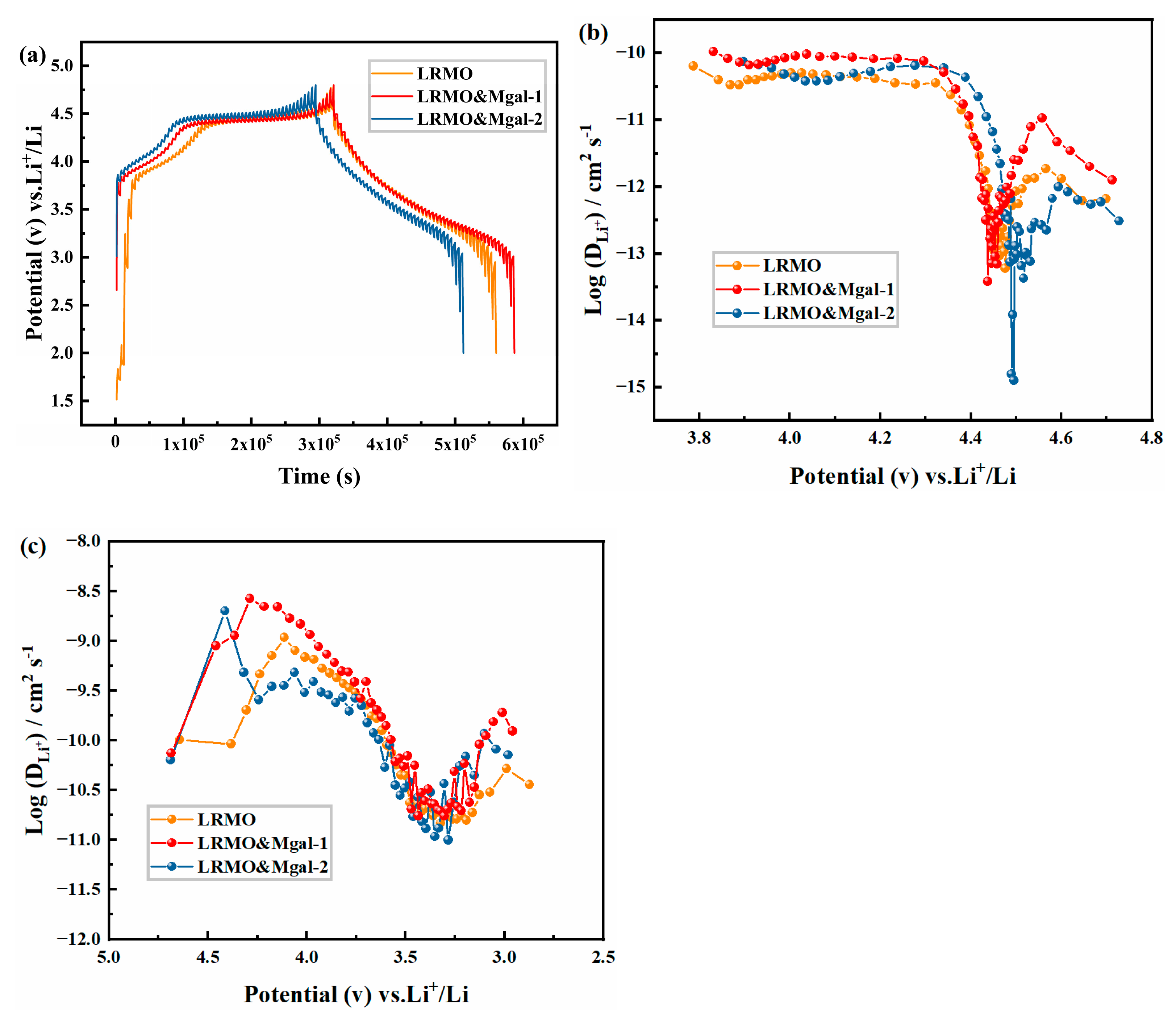
GITT was utilized to determine the diffusion coefficient of the samples. This value was computed using Equation (1) for ( DLi+).
D = 4 π τ m B V M M B S Δ E S Δ E τ 2 τ L 2 / D
where τ, n, VM, and S correspond to the relaxation time, number of moles of electrode material, molar volume, and contact area, respectively; and ΔEs and ΔEt denote the variation in pulse and constant-current charging and discharging voltage. Figure 10a displays the GITT curves, and the Li+ mobility of the three samples is stable until 4.3 V.
When charged up to the vicinity of 3.8 V, the Li+ diffusion mobility of the three samples is in the order of 6.35 × 10⁻¹¹ cm2·S−1, 1.05 × 10⁻¹⁰ cm2·S−1, and 7.37 × 10⁻¹¹ cm2·S−1, respectively. The LRMO&Mgal-1 material performed better Li+ diffusion mobility during charging and discharging. The findings demonstrate that the diffusion kinetic characteristics of Li+ can be efficiently enhanced by tiny Mg-Al co-doping.

4. Conclusions

In this paper, Li-rich manganese-based cathode materials with varying Mg-Al doping contents were prepared using the continuous co-precipitation method. The following conclusions were drawn:
  • The Mg-Al co-doped lithium-rich manganese-based cathode materials exhibit an enhanced layered structure. The mixing degree in the doped samples is further reduced compared to the original samples. The layer spacing of LRMO&Mgal-1 material increases, which is favorable for the lithium-ion transport;
  • SEM results reveal that the Mg-Al co-doped cathode material appears dense after sintering, which is effective in resisting erosion by by-products. TEM and EDS results indicate that the material is a well-developed layer structure with uniform element distribution after Mg-Al tiny co-doping. XPS results further highlight an increased average oxidation state of Mn and enhanced Mn4+ content, contributing to the alleviation of the Jahn–Teller effect;
  • The specific discharge capacity retention remained at 84.4% for the LRMO&Mgal-1 sample, even after 300 charge/discharge cycles at 1 C. The material exhibits excellent rate performance, achieving a specific capacity of 133.3 mAh·g−1 under high-current conditions of 5 C. The impedance test and GITT analysis indicate that the Li+ diffusion kinetics of the LRMO&Mgal-1 sample were effectively improved with Mg-Al tiny co-doping. These findings suggest that the addition of trace amounts of Mg-Al through co-doping has the potential to significantly improve the electrochemical properties of Li-rich Mn-based cathode materials.

Supplementary Materials

The following supporting information can be downloaded at: https://www.mdpi.com/article/10.3390/coatings15010003/s1, Figure S1: The cyclability of the single-Mg doped sample at 1 C current density; Figure S2: The rate capability of the single-Mg doped sample.

Author Contributions

Conceptualization, W.L. and W.D.; Methodology, Validation, W.L., M.L., K.L., J.L. (Jingyi Lin) and G.Z.; Formal Analysis, K.L., J.L. (Jingyi Lin) and G.Z.; Writing—original draft preparation, M.L. and X.Z.; Writing—review and editing, X.Z., J.L. (Jingyi Lin) and W.D.; Supervision, F.W. and J.L. (Jiageng Liu). Project Administration, F.W. and Y.W.; Funding Acquisition, F.W. and Y.W. All authors have read and agreed to the published version of the manuscript.

Funding

This research was funded by the National Undergraduate Innovation Program of the Ministry of Education of China (No. 202310595046) and Nanning Major Project of Science and Technology (No. 20231036).

Data Availability Statement

Data are contained within the article and Supplementary Materials.

Conflicts of Interest

The authors declare that they have no conflicts of interest.

References

  1. Wang, Y.L.; Huang, X.; Li, F. Enhanced high rate performance of Li[Li0.17Ni0.2Co0.05Mn0.58−xAlx]O2−0.5x cathode material for lithium-ion batteries. RSC Adv. 2015, 5, 49651–49656. [Google Scholar] [CrossRef]
  2. Zhao, J.Q.; Wang, Y. High-capacity full lithium-ion cells based on nanoarchitectured ternary manganese–nickel–cobalt carbonate and its lithiated derivative. J. Mater. Chem. A 2014, 2, 14947–14956. [Google Scholar] [CrossRef]
  3. Mezaal, M.A.; Qu, L.; Li, G.; Zhang, R.; Xuejiao, J.; Zhang, K.; Liu, W.; Lei, L. Promoting the cyclic and rate performance of lithium-rich ternary materials via surface modification and lattice expansion. RSC Adv. 2015, 5, 93048–93056. [Google Scholar] [CrossRef]
  4. Nitta, N.; Wu, F.; Lee, J.T. Li-ion battery materials: Present and future. Mater. Today 2015, 18, 252–264. [Google Scholar] [CrossRef]
  5. Meng, J.; Zhang, S.; Wei, X.; Yang, P.; Wang, S.; Wang, J.; Li, H.; Xing, Y.; Liu, G. Synthesis, structure and electrochemical properties of lithium-rich cathode material Li1.2Mn0.6Ni0.2O2 microspheres. RSC Adv. 2015, 5, 81565–81572. [Google Scholar] [CrossRef]
  6. Li, J.; Shunmugasundaram, R.; Doig, R.; Dahn, J.R. In Situ X-ray Diffraction Study of Layered Li–Ni–Mn–Co Oxides: Effect of Particle Size and Structural Stability of Core–Shell Materials. Chem. Mater. 2015, 28, 162–171. [Google Scholar] [CrossRef]
  7. Hong, J.; Gwon, H.; Jung, S.-K.; Ku, K.; Kang, K. Review—Lithium-Excess Layered Cathodes for Lithium Rechargeable Batteries. J. Electrochem. Soc. 2015, 162, A2447–A2467. [Google Scholar] [CrossRef]
  8. Ran, X.; Tao, J.; Chen, Z.; Yan, Z.; Yang, Y.; Li, J.; Lin, Y.; Huang, Z. Surface heterostructure induced by TiO2 modification in Li-rich cathode materials for enhanced electrochemical performances. Electrochim. Acta 2020, 353, 135959. [Google Scholar] [CrossRef]
  9. Yu, H.; Gao, Y.; Liang, X. Slightly Fluorination of Al2O3 ALD Coating on Li1.2Mn0.54Co0.13Ni0.13O2 Electrodes: Interface Reaction to Create Stable Solid Permeable Interphase Layer. J. Electrochem. Soc. 2019, 166, A2021–A2027. [Google Scholar] [CrossRef]
  10. Wu, F.; Lu, H.; Su, Y.; Li, N.; Bao, L.; Chen, S. Preparation and electrochemical characterization of Li(Li0.17Ni0.2Co0.05Mn0.58)O2 coated with LiAlO2. J. Appl. Electrochem. 2009, 40, 783–789. [Google Scholar] [CrossRef]
  11. Zhao, J.; Wang, Z.; Guo, H.; Li, X.; He, Z.; Li, T. Synthesis and electrochemical characterization of Zn-doped Li-rich layered Li[Li0.2Mn0.54Ni0.13Co0.13]O2 cathode material. Ceram. Int. 2015, 41, 11396–11401. [Google Scholar] [CrossRef]
  12. He, W.; Yuan, D.; Qian, J.; Ai, X.; Yang, H.; Cao, Y. Enhanced high-rate capability and cycling stability of Na-stabilized layered Li1.2[Co0.13Ni0.13Mn0.54]O2 cathode material. J. Mater. Chem. A 2013, 1, 11397–11403. [Google Scholar] [CrossRef]
  13. Weigel, T.; Schipper, F.; Erickson, E.M.; Susai, F.A.; Markovsky, B.; Aurbach, D. Structural and Electrochemical Aspects of LiNi0.8Co0.1Mn0.1O2 Cathode Materials Doped by Various Cations. ACS Energy Lett. 2019, 4, 508–516. [Google Scholar] [CrossRef]
  14. Huang, C.; Wang, Z.; Wang, H.; Huang, D.; He, Y.-B.; Zhao, S.-X. Mg2+ doping into Li sites to improve anionic redox reversibility and thermal stability of lithium-rich manganese-based oxides cathode. Mater. Today Energy 2022, 29, 101116. [Google Scholar] [CrossRef]
  15. Guo, H.; Xia, Y.; Zhao, H.; Yin, C.; Jia, K.; Zhao, F.; Liu, Z. Stabilization effects of Al doping for enhanced cycling performances of Li-rich layered oxides. Ceram. Int. 2017, 43, 13845–13852. [Google Scholar] [CrossRef]
  16. Shi, Z.; Wang, X.; Feng, W.; Song, C.; Chen, L.; Li, M. The effect on the properties of each element in the Li1.2Mn0.54Ni0.13Co0.13O2 material by the incorporation of Al. Ionics 2020, 26, 5951–5959. [Google Scholar] [CrossRef]
  17. Wang, Y.; Wang, L.; Guo, X.; Wu, T.; Yang, Y.; Wang, B.; Wang, E.; Yu, H. Thermal Stability Enhancement through Structure Modification on the Microsized Crystalline Grain Surface of Lithium-Rich Layered Oxides. ACS Appl. Mater. Interfaces 2020, 12, 8306–8315. [Google Scholar] [CrossRef]
  18. Bao, Y.; Wang, J.; Qian, Y.; Deng, Y.; Yang, X.; Chen, G. An appropriate amount of new spinel phase induced by control synthesis for the improvement of electrochemical performance of Li-rich layered oxide cathode material. Electrochim. Acta 2019, 330, 135240. [Google Scholar] [CrossRef]
  19. Yu, Y.; Yang, Z.; Zhong, J.; Liu, Y.; Li, J.; Wang, X.; Kang, F. A Simple Dual-Ion Doping Method for Stabilizing Li-Rich Materials and Suppressing Voltage Decay. ACS Appl. Mater. Interfaces 2020, 12, 13996–14004. [Google Scholar] [CrossRef]
  20. Toby, B.H. EXPGUI, a graphical user interface for GSAS. J. Appl. Crystallogr. 2001, 34, 210–213. [Google Scholar] [CrossRef]
  21. Zhao, T.; Zhou, N.; Zhang, X.; Xue, Q.; Wang, Y.; Yang, M.; Li, L.; Chen, R. Structure Evolution from Layered to Spinel during Synthetic Control and Cycling Process of Fe-Containing Li-Rich Cathode Materials for Lithium-Ion Batteries. ACS Omega 2017, 2, 5601–5610. [Google Scholar] [CrossRef] [PubMed]
  22. Zhao, Y.; E, Y.; Fan, L.; Qiu, Y.; Yang, S. A new route for the electrodeposition of platinum–nickel alloy nanoparticles on multi-walled carbon nanotubes. Electrochim. Acta 2007, 52, 5873–5878. [Google Scholar] [CrossRef]
  23. Liang, T.; Zeng, W.; Yang, L.; Liu, S.; Huang, Y.; He, H.; Chen, X.; He, A. Electrochemical performance of the Li-rich layered Li1.2Mn0.54Ni0.13Co0.13O2 cathode material influenced by Fe3+ doping. J. Alloys Compd. 2022, 910, 164862. [Google Scholar] [CrossRef]
  24. Qiu, B.; Zhang, M.; Wu, L.; Wang, J.; Xia, Y.; Qian, D.; Liu, H.; Hy, S.; Chen, Y.; An, K.; et al. Gas-solid interfacial modification of oxygen activity in layered oxide cathodes for lithium-ion batteries. Nat. Commun. 2016, 7, 12108. [Google Scholar] [CrossRef] [PubMed]
  25. Tang, W.; Duan, J.; Xie, J.; Qian, Y.; Li, J.; Zhang, Y. Dual-Site Doping Strategy for Enhancing the Structural Stability of Lithium-Rich Layered Oxides. ACS Appl. Mater. Interfaces 2021, 13, 16407–16417. [Google Scholar] [CrossRef]
  26. Nakamura, T.; Ohta, K.; Hou, X.; Kimura, Y.; Tsuruta, K.; Tamenori, Y.; Aso, R.; Yoshida, H.; Amezawa, K. Oxygen defect engineering for the Li-rich cathode material Li1.2Ni0.13Co0.13Mn0.54O2−δ. J. Mater. Chem. A 2020, 9, 3657–3667. [Google Scholar] [CrossRef]
  27. Galakhov, V.R.; Demeter, M.; Bartkowski, S.; Neumann, M.; Ovechkina, N.A.; Kurmaev, E.Z.; Lobachevskaya, N.I.; Mukovskii, Y.M.; Mitchell, J.; Ederer, D.L. Mn 3s exchange splitting in mixed-valence manganites. Phys. Rev. B 2002, 65, 113102. [Google Scholar] [CrossRef]
  28. Carabineiro, S.A.C.; Bastos, S.S.T.; Órfão, J.J.M.; Pereira, M.F.R.; Delgado, J.J.; Figueiredo, J.L. Carbon Monoxide Oxidation Catalysed by Exotemplated Manganese Oxides. Catal. Lett. 2009, 134, 217–227. [Google Scholar] [CrossRef]
  29. Simonelli, L.; Sorrentino, A.; Marini, C.; Ramanan, N.; Heinis, D.; Olszewski, W.; Mullaliu, A.; Birrozzi, A.; Laszczynski, N.; Giorgetti, M.; et al. Role of Manganese in Lithium- and Manganese-Rich Layered Oxides Cathodes. J. Phys. Chem. Lett. 2019, 10, 3359–3368. [Google Scholar] [CrossRef] [PubMed]
  30. Huang, Z.; Wang, Z.; Zheng, X.; Guo, H.; Li, X.; Jing, Q.; Yang, Z. Effect of Mg doping on the structural and electrochemical performance of LiNi0.6Co0.2Mn0.2O2 cathode materials. Electrochim. Acta 2015, 182, 795–802. [Google Scholar] [CrossRef]
  31. Wang, Y.X.; Shang, K.H.; He, W.; Ai, X.P.; Cao, Y.L.; Yang, H.X. Magnesium-Doped Li1.2[Co0.13Ni0.13Mn0.54]O2 for Lithium-Ion Battery Cathode with Enhanced Cycling Stability and Rate Capability. ACS Appl. Mater. Interfaces 2015, 7, 13014–13021. [Google Scholar] [CrossRef] [PubMed]
  32. Sun, Y.; Zhang, L.; Dong, S.; Zeng, J.; Shen, Y.; Li, X.; Ren, X.; Ma, L.; Hai, C.; Zhou, Y. Improving the electrochemical performances of Li-rich Li1.2Ni0.13Co0.13Mn0.54O2 through cooperative doping of Na+ and Mg2+. Electrochim. Acta 2022, 414, 140169. [Google Scholar] [CrossRef]
  33. Liu, Q.; Su, X.; Lei, D.; Qin, Y.; Wen, J.; Guo, F.; Wu, Y.A.; Rong, Y.; Kou, R.; Xiao, X.; et al. Approaching the capacity limit of lithium cobalt oxide in lithium ion batteries via lanthanum and aluminium doping. Nat. Energy 2018, 3, 936–943. [Google Scholar] [CrossRef]
  34. Zou, L.; Li, J.; Liu, Z.; Wang, G.; Manthiram, A.; Wang, C. Lattice doping regulated interfacial reactions in cathode for enhanced cycling stability. Nat. Commun. 2019, 10, 3447. [Google Scholar] [CrossRef]
  35. He, X.; Wu, J.; Zhu, Z.; Liu, H.; Li, N.; Zhou, D.; Hou, X.; Wang, J.; Zhang, H.; Bresser, D.; et al. Chemical and structural evolutions of Li–Mn-rich layered electrodes at different current densities. Energy Environ. Sci. 2022, 15, 4137–4147. [Google Scholar] [CrossRef]
  36. Fu, X.; Zhou, X.; Zhao, D.; Liang, Y.; Wang, P.; Zhang, N.; Tuo, K.; Lu, H.; Cai, X.; Mao, L.; et al. Study on electrochemical performance of Al-substitution for different cations in Li-rich Mn-based materials. Electrochim. Acta 2021, 394, 139136. [Google Scholar] [CrossRef]
  37. Liang, Y.; Li, S.; Xie, J.; Yang, L.; Li, W.; Li, C.; Ai, L.; Fu, X.; Cui, X.; Shangguan, X. Synthesis and electrochemical characterization of Mg–Al co-doped Li-rich Mn-based cathode materials. New J. Chem. 2019, 43, 12004–12012. [Google Scholar] [CrossRef]
  38. Koga, H.; Croguennec, L.; Ménétrier, M.; Mannessiez, P.; Weill, F.; Delmas, C.; Belin, S. Operando X-ray Absorption Study of the Redox Processes Involved upon Cycling of the Li-Rich Layered Oxide Li1.20Mn0.54Co0.13Ni0.13O2 in Li Ion Batteries. J. Phys. Chem. C 2014, 118, 5700–5709. [Google Scholar] [CrossRef]
  39. Liu, Y.; Yang, Z.; Zhong, J.; Li, J.; Li, R.; Yu, Y.; Kang, F. Surface-Functionalized Coating for Lithium-Rich Cathode Material to Achieve Ultra-High Rate and Excellent Cycle Performance. ACS Nano 2019, 13, 11891–11900. [Google Scholar] [CrossRef] [PubMed]
  40. Gan, Y.; Wang, Y.; Han, J.; Zhang, L.; Sun, W.; Xia, Y.; Huang, H.; Zhang, J.; Liang, C.; Zhang, W. Synthesis and electrochemical performance of nano TiO2(B)-coated Li[Li0.2Mn0.54Co0.13Ni0.13]O2 cathode materials for lithium-ion batteries. New J. Chem. 2017, 41, 12962–12968. [Google Scholar] [CrossRef]
  41. House, R.A.; Rees, G.J.; Pérez-Osorio, M.A.; Marie, J.-J.; Boivin, E.; Robertson, A.W.; Nag, A.; Garcia-Fernandez, M.; Zhou, K.-J.; Bruce, P.G. First-cycle voltage hysteresis in Li-rich 3d cathodes associated with molecular O2 trapped in the bulk. Nat. Energy 2020, 5, 777–785. [Google Scholar] [CrossRef]
  42. Yang, G.; Chu, Y.; Yu, J.; Qu, J.; Yang, S.; Tan, C.; Lai, F.; Jin, Q.; Wang, H.; Zhang, X. Uniform amorphous MgxByOz coating combined with Vo for highly stable Li-Rich Mn-based cathode material. Chem. Eng. J. 2024, 486, 150315. [Google Scholar] [CrossRef]
  43. Liu, X.; Jiang, C.; Yu, B.; Wang, M.; Jin, Y.; Fu, Z.; Chen, J.; Ma, Z.; Guo, B.; Huang, Y.; et al. Fundamental mechanism revealed for lithium deficiencies engineering in a new spherical Li-Rich Mn-based layered Li1.23Mn0.46Ni0.246Co0.046Al0.015O2 cathode. Electrochim. Acta 2022, 418, 140379. [Google Scholar] [CrossRef]
  44. Xu, M.; Chen, Z.; Zhu, H.; Yan, X.; Li, L.; Zhao, Q. Mitigating capacity fade by constructing highly ordered mesoporous Al2O3/polyacene double-shelled architecture in Li-rich cathode materials. J. Mater. Chem. A 2015, 3, 13933–13945. [Google Scholar] [CrossRef]
  45. Ding, X.; Li, Y.-X.; Chen, F.; He, X.-D.; Yasmin, A.; Hu, Q.; Wen, Z.-Y.; Chen, C.-H. In situ formation of LiF decoration on a Li-rich material for long-cycle life and superb low-temperature performance. J. Mater. Chem. A 2019, 7, 11513–11519. [Google Scholar] [CrossRef]
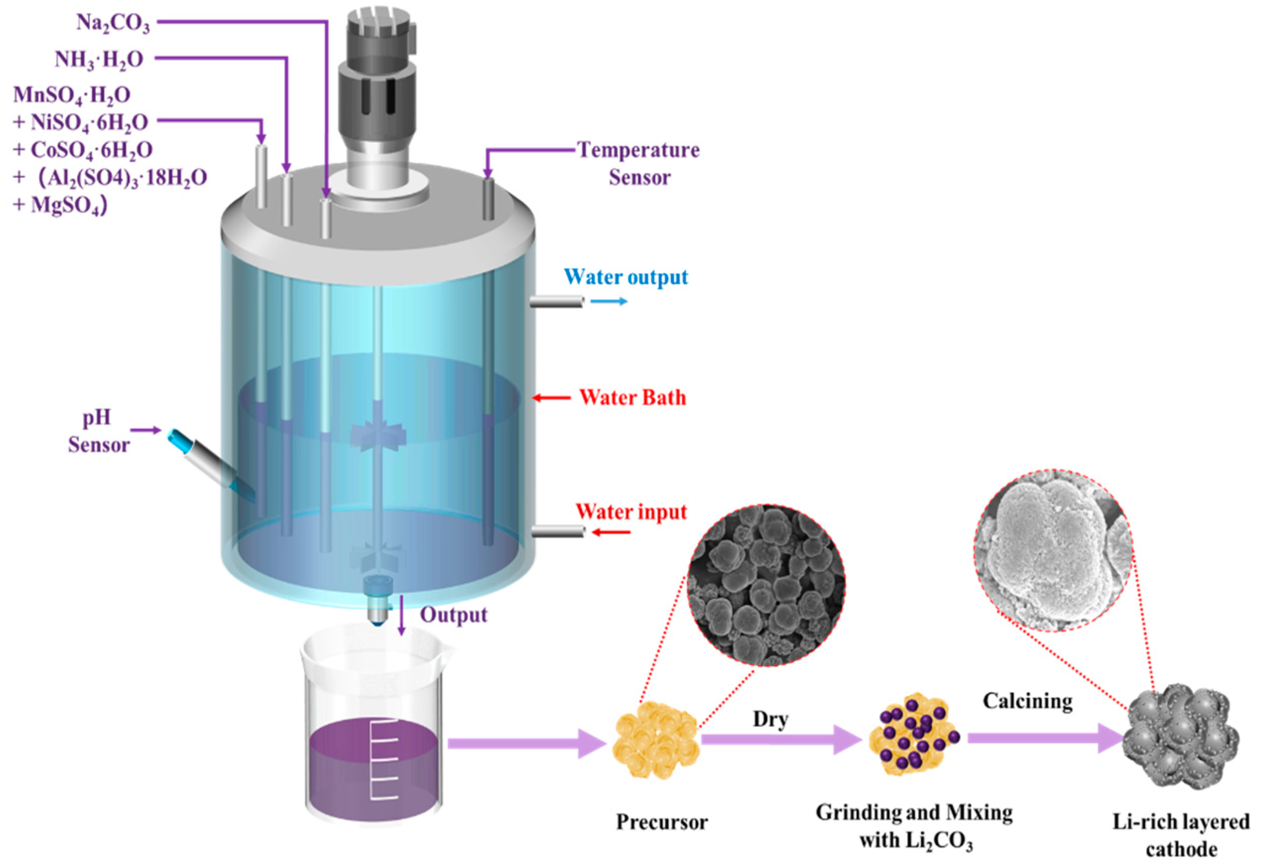
Figure 1. Schematic diagram of synthesis of lithium-rich manganese-based precursors and cathode.
Coatings 15 00003 g001
Figure 2. XRD patterns of LMR materials.
Coatings 15 00003 g002
Figure 3. Rietveld refined XRD spectra of (a) LRMO; (b) LRMO&Mgal-1.
Coatings 15 00003 g003
Figure 4. SEM images of the materials: (a) LRMO precursor; (b) LRMO&Mgal-1 precursor; (c) LRMO&Mgal-2 precursor; (d) LRMO cathode material; (e) LRMO&Mgal-1 cathode material; (f) LRMO&Mgal-2 cathode material; (g) enlarged image of LRMO cathode material; (h) enlarged image of LRMO&Mgal-1; (i) enlarged image of LRMO&Mgal-2 cathode material.
Coatings 15 00003 g004
Figure 5. (a) TEM image of LRMO&Mgal-1 material; (b) corresponding FFT diffraction spots; (ch) EDS mapping results and element distribution.
Coatings 15 00003 g005
Figure 6. XPS spectra of the original LRMO and LRMO&Mgal-1: (ad) are Ni 2p, Co 2p, O 2p, and Mn 3s, respectively. Comparison of valence state content: (e) Ni2+/Ni3+; (f) Co3+/Co4+; (g) O2–/OX–/Oche.sor.
Coatings 15 00003 g006
Figure 7. (a) The cyclability of LRM samples at 1 C current density; (b) the rate capability of the LRM samples.
Coatings 15 00003 g007
Figure 8. (a) Initial charge–discharge curves of LRMO, LRMO&Mgal-1, and LRMO&Mgal-2 samples at a current density of 0.1 C; (bd) CV curves of the samples with a scanning rate of 0.1 mV/s.
Coatings 15 00003 g008
Figure 9. (a) Nyquist plots of LRMO, LRMO&Mgal-1, and LRMO&Mgal-2 samples after first cycle of 0.1 C; (b) graphs of the corresponding ω−1/2 and z’.
Coatings 15 00003 g009
Figure 10. LRMO, LRMO&Mgal-1, and LRMO&Mgal-2 samples: (a) GITT curve; (b) log (DLi+) of the charging process; (c) log of discharge process (DLi+).
Coatings 15 00003 g010
Table 1. Lattice parameters of LRMO and LRMO&Mgal-1 samples.
Samplea/Åc/Åc/a
LRMO2.851 (8)14.233 (6)4.9910
LRMO&Mgal-12.852 (1)14.240 (4)4.9930
Table 2. Impedance fitting results of LRMO, LRMO&Mgal-1, and LRMO&Mgal-2 after first cycle.
SampleRs (Ω)Rf (Ω)Rct (Ω)R (Ω)σ
LRMO1.1672.28165.90239.18217.7
LRMO&Mgal-11.1547.3074.26121.56179.3
LRMO&Mgal-21.56230.5254.4484.90555.2
Disclaimer/Publisher’s Note: The statements, opinions and data contained in all publications are solely those of the individual author(s) and contributor(s) and not of MDPI and/or the editor(s). MDPI and/or the editor(s) disclaim responsibility for any injury to people or property resulting from any ideas, methods, instructions or products referred to in the content.