Article

Facile Synthesis of Iron Phosphide Nanoparticles in 3D Porous Carbon Framework as Superior Anodes for Sodium-Ion Batteries

Fujian Key Laboratory of Surface and Interface Engineering for High Performance Materials, College of Materials, Xiamen University, Xiamen 361005, China
*
Authors to whom correspondence should be addressed.
Coatings 2025, 15(1), 85; https://doi.org/10.3390/coatings15010085
Submission received: 25 December 2024 / Revised: 11 January 2025 / Accepted: 13 January 2025 / Published: 14 January 2025
(This article belongs to the Special Issue Coatings for Batteries and Energy Storage)

Abstract

:
Iron phosphide (FeP) represents a promising anode material for sodium-ion batteries, attributed to its significant theoretical capacity, moderate operating potential, and natural abundance. However, due to the low conductivity and significant volume expansion of FeP electrodes, their specific capacity and cycle life decrease rapidly during charging and discharging. In this study, we synthesized FeP nanoparticles supported on a three-dimensional porous carbon framework composite (FeP@PCF) using a straightforward colloidal blow molding method, employing iron nitrate nonahydrate and polyvinylpyrrolidone as raw materials. The nanoscale size of the FeP particles, along with the abundant mesopores and high specific surface area of the 3D porous carbon framework, contribute to the impressive sodium storage performance of FeP@PCF. It is revealed that FeP@PCF achieves a remarkable capacity of 196.6 mA h g−1 at a current density of 1.0 A g−1. Furthermore, after 800 cycles at this current density, it retains a capacity of 172.4 mA h g−1, demonstrating excellent cycling performance. Kinetic and dynamic studies indicate that this exceptional performance is largely attributed to the well-designed FeP@PCF, which exhibits a high capacitive contribution of 88.3% at a scan rate of 1 mV s−1.

1. Introduction

Sodium-ion batteries (SIBs) have emerged as a prominent area of research within the field of large-scale electrochemical energy storage. Their increased attention can be attributed to several factors, including the availability of abundant resources, their cost-effectiveness, and their environmentally friendly characteristics [1,2,3]. Sodium-ion batteries operate on a “rocking chair” mechanism similar to that of lithium-ion batteries, and their standard electrode potentials are comparable to those of lithium-ion batteries. Currently, one of the main challenges in the development of sodium-ion batteries is to find suitable electrode materials. Research has indicated that many materials known for their high energy density and excellent cycle performance in LIBs are unsuitable for SIBs. This is primarily due to the greater ionic radius of sodium ions (Na+, 1.02 Å) in comparison with that of lithium ions (Li+, 0.76 Å) [4,5,6]. The larger ionic radius results in slower diffusion kinetics during electrochemical charging and discharging, as well as significant volume expansion of the material structure, leading to the fragmentation of electrodes.
Among various anode materials, transition metal phosphides (TMPs) [7,8], especially iron phosphide (FeP), have garnered significant attention due to their affordability, high theoretical capacity, and relatively low redox potential (vs. Na/Na+) [9]. The orthorhombic structure of iron phosphide (FeP) often interacts with sodium during the conversion reaction, resulting in the formation of a metastable ternary tetragonal phase known as NaFeP [8]. This phase can incorporate multiple sodium atoms and shows exceptional performance in sodium storage applications. During the first discharge, it ultimately transforms into Na3P and Fe0, creating a nanocomposite made up of Fe0 nanoparticles enclosed within a Na3P structure. However, the low conductivity of FeP and the significant volume expansion during cycling result in the rapid decline in its specific capacity and cycle life [10,11]. To tackle these challenges, preparing FeP with different nanostructures is an effective strategy. Nanomaterials can shorten the diffusion paths of Na+ ions and electrons, which helps accelerate the kinetics of the electrodes. Additionally, combining FeP with carbon-based materials is expected to reduce the volume expansion and aggregation of FeP during cycling, while also enhancing its electrical conductivity [12]. Shi et al. designed a novel structure of FeP@OCF, in which FeP quantum dots are confined within P-doped three-dimensional octahedral carbon frameworks and carbon nanotubes. Compared to pure FeP, this new structure significantly improves both the diffusion control capability in the plateau region by 2.3 times and the surface control capability in the slope region by 2.9 times. As a result, it achieves an excellent reversible capacity of 674 mAh g−1 and an unprecedented high-rate performance of 262 mAh g−1 at a current rate of 20 A g−1 [11]. Ren et al. developed carbon nanosheets embedded with FeP, which demonstrate a remarkable capacity of 516.6 mAh g−1 at a current density of 0.1 A g−1 [12]. Furthermore, introducing different carbon structures, such as graphene [13], carbon nanofiber [14], and carbon nanosheets [15], is being explored to enhance sodium storage capacity.
FeP@PCF composites were prepared using a straightforward colloidal blow molding method. The FeP nanoparticles, along with the abundant mesopores and high specific surface area of the 3D porous carbon framework, contribute to the excellent sodium storage performance of FeP@PCF. It achieves a high capacity of 196.6 mA h g−1 at a current density of 1.0 A g−1. Additionally, after 800 cycles at 1.0 A g−1, a capacity of 172 mA h g−1 is maintained, indicating superior cycling performance. Cyclic voltammetry curves at different scanning rates show that as the scanning rate increases from 0.2 to 1.0 mV s−1, the contribution of FeP@PCF also increases, rising from 77.2% at 0.2 mV s−1 to 88.3% at 1.0 mV s−1.

2. Materials and Methods

1.
Synthesis of Fe3C@PCF
First, 2 g of polyvinylpyrrolidone (PVP, K30) and 3 g of Fe(NO3)3∙9H2O were dissolved in 60 mL of deionized water and stirred to create a homogeneous solution. Then, the resulting solution was transferred to an air-drying oven and dried at 80 °C overnight. After drying, the material was collected and ground into a fine powder using an agate mortar. To obtain the Fe3C@PCF material, 1.5 g of the powder was heated to 800 °C at a rate of 5 °C/min in an argon atmosphere for a duration of 2 h.
2.
Synthesis of FeP@PCF
The phosphating process was carried out in a tube furnace. Then, 2.0 g NaH2PO2 and 0.1 g Fe3C@PCF powder were placed in the upstream and downstream sections of the quartz boat, respectively. The samples were annealed at 400 °C for 3 h at a ramp rate of 5 °C/min under a controlled argon flow rate of 60 sccm. Phosphorus vapors produced from the annealing of NaH2PO2 reacted with Fe3C to form FeP nanoparticles. After the samples cooled to room temperature, the resulting black powder of FeP@PCF was collected.
3.
Synthesis of pure FeP NPs
Pure FeP NPs were synthesized using the solvothermal method for comparison. First, 1.3 g of FeCl3∙6H2O and 3.7 g of NaAc were dissolved in 40 mL of ethylene glycol, followed by vigorous stirring for 30 min. The resulting mixture was then transferred to a Teflon stainless-steel autoclave (50 mL) and transferred to an oven at 200 °C for 8 h. After cooling to room temperature, the collected product was centrifuged and washed three times with deionized water and absolute ethanol, then dried at 80 °C under vacuum for 13 h. Finally, the collected pure Fe3O4 NPs powder was phosphated in the same way as the synthesis of FeP@PCF to obtain pure FeP NPs.

3. Materials Characterization

The material structure was thoroughly analyzed using an X-ray diffractometer (XRD, Rigaku Ultima IV, Tokyo, Japan, Cu Kα radiation). The morphology and structural characteristics were assessed through scanning electron microscopy (SEM, Hitachi SU-70, Tokyo, Japan) and transmission electron microscopy (TEM, TECNAI-F30, Philips-FEI, Amsterdam, The Netherlands). X-ray photoelectron spectroscopy (XPS, Thermo Scientific, Waltham, MA, USA) measurements were carried out utilizing the EscaLab250Xi system. The graphitization of the material was investigated utilizing Raman spectroscopy (Jobin-Yvon, Paris, France). Nitrogen adsorption and desorption isotherms were obtained through the TriStar 3020 system. Furthermore, thermogravimetric analysis (TGA) was conducted with the SDT-Q600 thermal analyzer (TA Instruments, New Castle, DE, USA) in an air atmosphere.

4. Electrochemical Measurements

The slurry was prepared by combining FeP@PCF composite powder, Super P, and sodium carboxymethyl cellulose (CMC) in a mass ratio of 7:2:1, along with water as the solvent. This mixture was then coated onto copper foil and dried overnight. The loading mass for each electrode is approximately 1.0 mg cm−2. Inside a glove box under an argon atmosphere, sodium tablets served as the counter electrode, and a glass fiber diaphragm (Whatman, GF/D, London, UK) was utilized as a separator, using an electrolyte consisting of 1 M NaClO4 in a 1:1 volume mixture of ethylene carbonate (EC) and dimethyl carbonate (DMC), supplemented with 5% fluoroethylene carbonate (FEC) to construct a 2032 button battery. A battery testing system (LAND CT2001A) was employed to evaluate the electrochemical performance of these cells across a voltage range of 0.01 to 2.5 V. Cyclic voltammetry (CV) and electrochemical impedance spectroscopy (EIS) were conducted using an electrochemical workstation (CHI660E). The complete cell was assembled with commercial Na3V2(PO4)3 as the cathode and FeP@PCF as the anode, utilizing 1 M NaClO4 in a 1:1 mixture of EC and diethyl carbonate (DEC) with 5% FEC as the electrolyte. The mass ratio of the cathode to the anode was approximately 3.2 to 1.

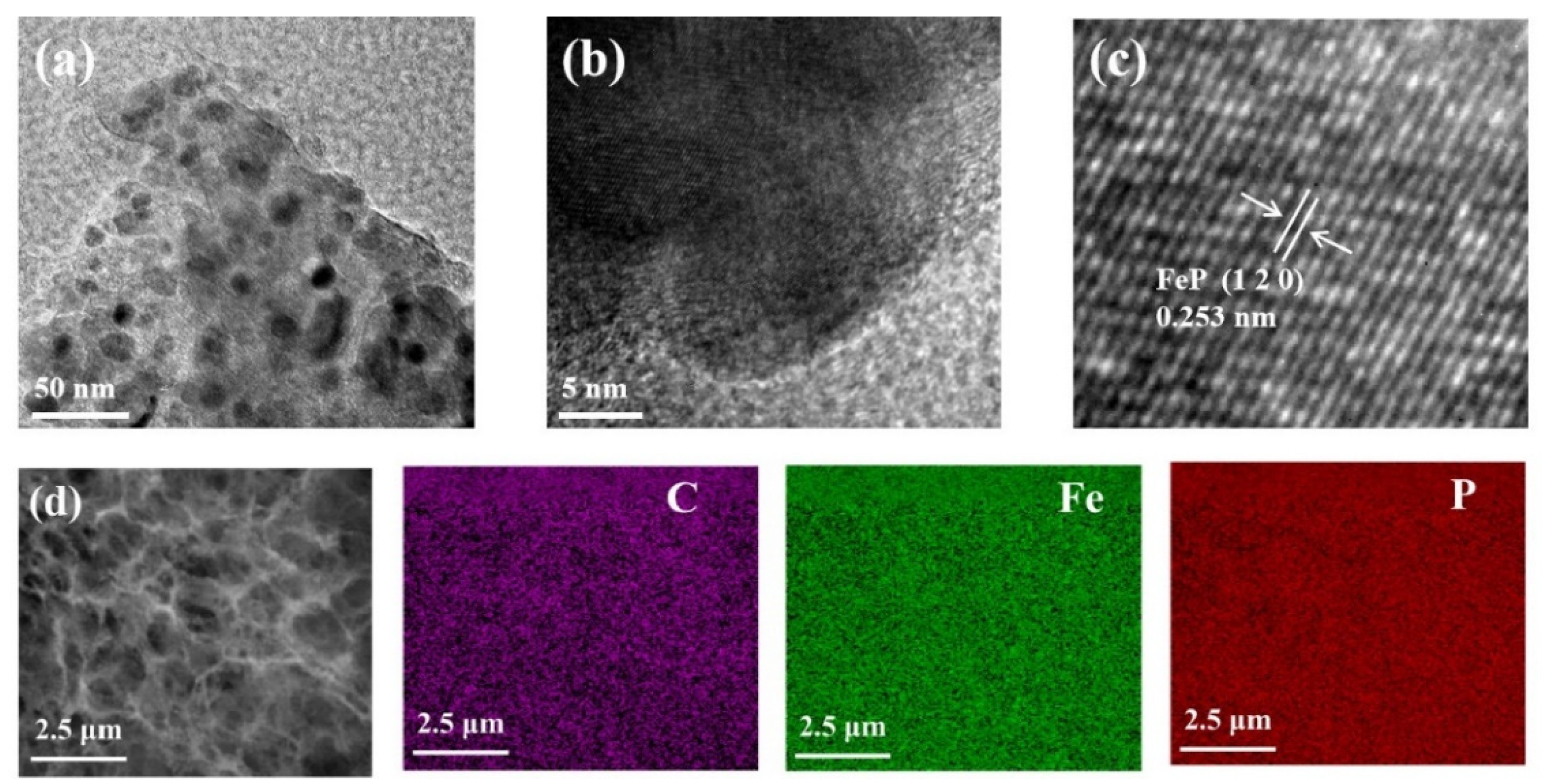
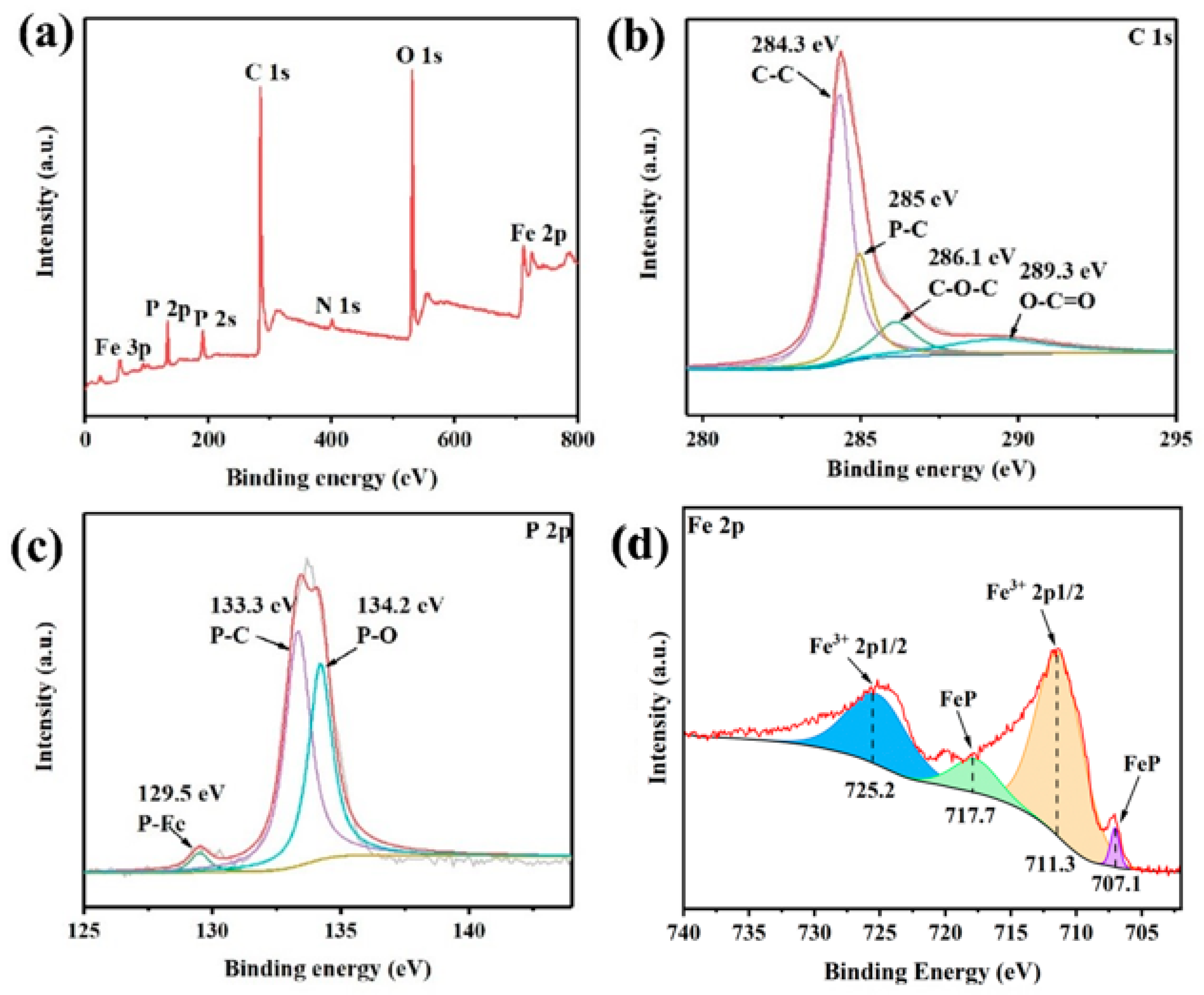
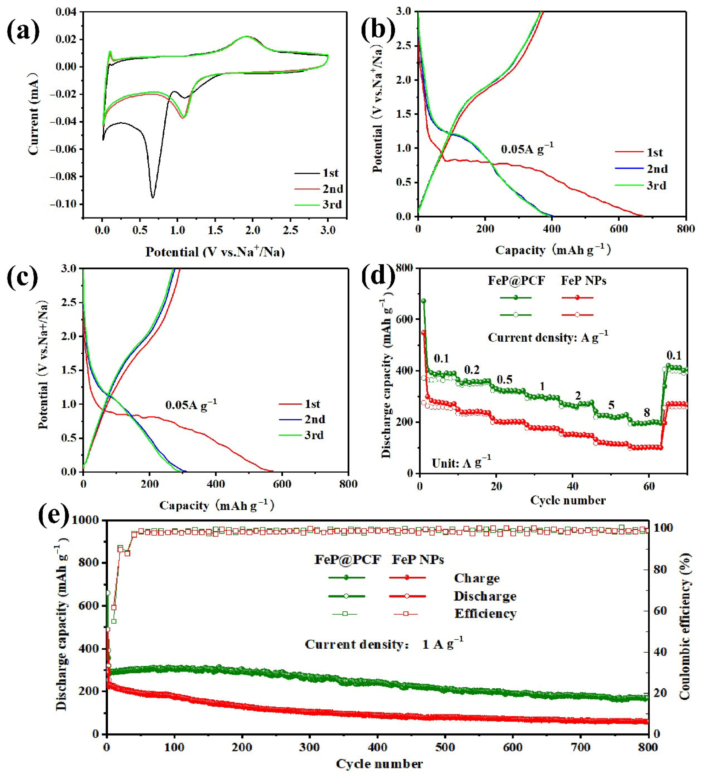
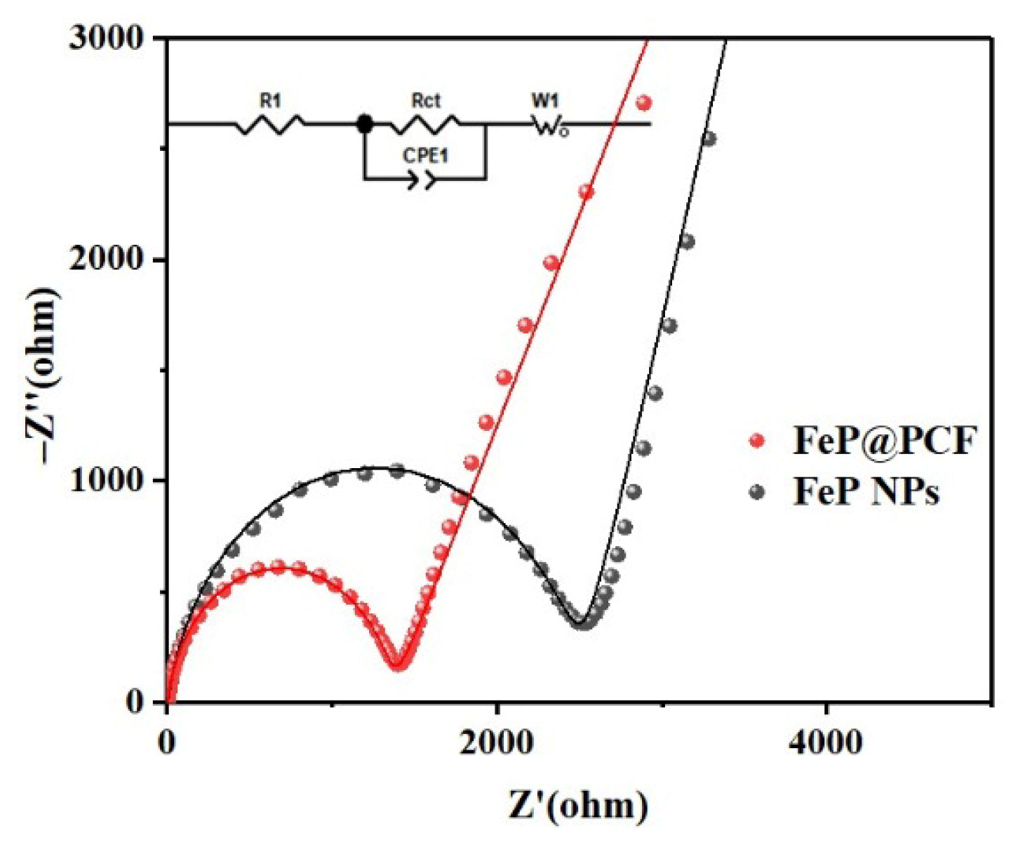
5. Results and Discussion

As illustrated in Figure 1a, FeP@PCF was prepared from iron nitrate nonahydrate and polyvinylpyrrolidone (PVP) as raw materials by the simple colloidal blow molding method. During the carbonization process, the molten PVP is transformed into numerous polymer foams due to the significant amount of gas produced by the rapid decomposition of Fe(NO3)3. These foams stack together to create a three-dimensional porous carbon framework. Concurrently, Fe3+ is reduced through carbothermal processes and alloyed with carbon to form Fe3C, which is uniformly embedded within the carbon matrix. Finally, low-temperature gas-phase phosphating with sodium hypophosphite is performed to produce FeP@PCF.
Figure S1a–c presents the SEM images of the Fe3C@PCF samples. These images reveal that the overall structure of the material consists of a three-dimensional porous carbon framework, which is uniformly decorated with Fe3C nanoparticles. In comparison, the structure of the FeP@PCF sample (Figure 1b,c) is similar to that of the Fe3C@PCF sample. However, it is essential to note that the FeP nanoparticles are slightly larger than the Fe3C nanoparticles. This size difference arises from the aggregation and fusion of the nanoparticles into larger particles during the phosphating process, which occurs to minimize surface energy [16,17]. This thoughtfully designed structure promotes the diffusion of Na+ ions among the active FeP nanoparticles, enhancing the material’s performance. Additionally, the carbon matrix provides adequate electrical conductivity while effectively accommodating the significant volume changes in the FeP nanoparticles during the charging and discharging cycles. Figure S1d–f displays the microscopic morphology of the FeP nanoparticles, which have a diameter of approximately 300 nm when prepared using either the solvothermal method or the gas-phase phosphating method.
The phase of the composites is determined by XRD. Figure 1c presents the XRD pattern of FeP@PCF. A comparison with the standard PDF card indicates that the primary phase present is FeP (No. 71-2662) [17,18]. Interestingly, an additional diffraction peak at approximately 26° can be detected, which is attributed to the (0 0 2) lattice plane of the carbon nanoframe [19]. XRD analysis of the Fe3C@PCF, Fe3O4 NP, and FeP NP samples (Figure S3b,c) is conducted, which confirms their successful synthesis. As illustrated, Fe3C@PCF also has a primary phase of Fe3C (No. 75-0910) and a diffraction peak of carbon at 26°. The crystallinity of the FeP nanoparticles is much lower than that of the Fe3O4 nanoparticles, suggesting that the size of the FeP nanoparticles may be smaller.
The microstructure of the FeP@PCF and FeP nanoparticle composites was further analyzed using TEM. As presented in Figure 2a, nearly spherical FeP nanoparticles, measuring between 10 and 20 nm, were uniformly distributed across the thin carbon matrix. The high-resolution TEM image (Figure 2c) reveals lattice fringes with a spacing of 0.253 nm, which can be attributed to the (1 2 0) plane of FeP (JCPDS No: 71-2662). EDS elemental mappings of the FeP@PCF composites also confirmed that the FeP nanoparticles are evenly distributed on the carbon nano framework (Figure 2d). In comparison, the TEM images of the FeP nanoparticle material show a diameter of approximately 300 nm and uniform size (Figure S2a,b). In the high-resolution images (HRTEM, Figure S2c), lattice fringes with a spacing of 0.273 nm were identified, corresponding to the (0 1 1) plane of FeP (JCPDS No. 71-2662) [20,21].
The loading mass of FeP nanoparticles was determined using TGA in air. As illustrated in Figure 3a, the weight loss observed at temperatures up to 200 °C is primarily due to the evaporation of adsorbed water. The fluctuations in weight between 200 °C and 550 °C are attributed to two simultaneous processes: the oxidation of FeP to FePO4, which increases the weight, and the combustion of the carbon component in FeP@PCF, which decreases the weight. From 550 °C to 900 °C, the degradation of the sample’s mass is dominated by the combustion of the carbon component. By 900 °C, the carbon component had been completely burned off, and FeP had been fully oxidized to FePO4, resulting in a total mass loss of 5.41%. It is calculated that the mass percentage of FeP in the composite is 52.48% [20,22,23]. In the Raman spectrum of FeP@PCF (Figure 3b), the D peak at 1344 cm−1 indicates a disordered carbon structure, while the G peak at 1589 cm−1 is associated with graphitic carbon. The higher ID/IG ratio of 1.07 suggests that the carbon nanoframes contain a significant number of defect structures [24,25]. Figure 3c,d presents the N2 adsorption–desorption isotherm and the pore size distribution curve of the FeP@PCF material. The results indicate that FeP@PCF has a specific surface area of 131.7 m2 g−1, with a pore structure predominantly consisting of mesopores and an average pore diameter of 5.7 nm. This mesoporous structure enhances the penetration of the electrolyte, which increases the electrode reaction surface area. Additionally, it effectively accommodates the volume changes that occur in iron phosphide during the sodiumization and de-sodiumization processes, thereby improving the structural stability and recyclability of the material [8,17,26].
Figure 4 shows the investigation of the valence states of the elements in FeP@PCF using XPS. The full spectrum of FeP@PCF (Figure 4a) confirms the presence of C, P, O, and Fe atoms. As shown in Figure 4b, the high-resolution C 1s spectrum is divided into four peaks, corresponding to C-C (284.3 eV), P-C (285 eV), C-O-C (286.1 eV), and O-C=O (289.3 eV) bonds [27,28,29]. In the high-resolution P 2p spectrum (Figure 4c), a P-Fe peak is observed at 129.5 eV, while the P-O peak at 134.0 eV is attributed to the surface oxidation of FeP@PCF as a result of exposure to air [14]. The presence of the P-C peak at 129.5 eV, which is also observed at 285 eV in the C 1s spectrum, means that the bound FeP nanoparticles are securely attached to the porous nanocarbon framework through a chemical linkage. This strong interaction between the porous nanocarbon framework and the FeP nanoparticles helps prevent the nanoparticles from dissolving into the electrolyte [30]. In addition, the Fe 2p spectrum (Figure 4d) shows three peaks associated with Fe-P bonds—(707.1 eV), Fe3+ 2p3/2 (711.3 eV), and Fe3+ 2p1/2 (725.2 eV)—further supporting the successful formation of FeP [31].
Figure 5a illustrates the first three CV curves of the FeP@PCF electrode, recorded at a scan rate of 0.1 mV s−1 versus Na/Na⁺ within the voltage range of 0.01 to 3.0 V. In the initial cycle, a broad reduction peak observed at 1.11 V during discharge is attributed to the conversion of FeP into the intermediate NaxFeP, leading to the formation of metallic Fe and Na3P. The prominent peak observed at 0.67 V during the initial cathodic scan corresponds to the creation of a solid–electrolyte interface (SEI) film. Conversely, during the anodic scan, a broad oxidation peak at 1.9 V arises from the dealloying process involving the Na3P and P phases [32,33,34]. The electrochemical activation of FeP during the initial discharge results in a notable shift in the reduction peak to a lower potential (approximately 1.07 V vs. Na/Na⁺) in subsequent cathodic scans, indicating enhanced electrode reaction kinetics. The subsequent curves overlap significantly, showcasing the remarkable cycling stability of the FeP@PCF pair as anodes in sodium-ion batteries (SIBs). Coupled with the CV results and the relevant literature, the charge–discharge process equation for FeP@PCF is as follows [35]:
FeP + 3Na+ + 3e → Na3P + Fe (first discharge)
Na3P ↔ P + 3Na+ + 3e
The FeP@PCF electrodes demonstrated initial discharge and charge specific capacities of 672.3 mA h g−1 and 372.9 mA h g−1, respectively. The initial Coulombic efficiency (ICE) was recorded at 55.5% (see Figure 5b). The low first-cycle Coulombic efficiency observed in iron phosphide materials mainly results from electrolyte decomposition and the formation of an SEI. This issue can be addressed by implementing pre-basinization techniques. During the first discharge, the extended discharge plateau at 0.8–0.7 V is attributed to the conversion of FeP into Fe nanoparticles and Na3P, along with the formation of an SEI film.
In contrast, the FeP NP electrodes exhibited initial discharge/charge specific capacities of 573.7 and 291.5 mA h g−1, respectively, and an initial Coulombic efficiency (ICE) of only 50.8% (Figure 5c). The performance rates of the FeP@PCF and FeP NP electrodes at various current densities are illustrated in Figure 5d. The FeP@PCF electrode demonstrates impressive reversible specific capacities of 391.2, 361.5, 321.3, 295.3, 276.3, 228.5, and 196.6 mA h g−1 at current densities of 100, 200, 500, 1000, 5000, and 8000 mA g−1, respectively. In comparison, FeP nanoparticles (NPs) exhibit lower specific capacities of 272.4, 237.4, 203.6, 175.1, 148.8, 116.8, and 102.5 mA h g−1 at the same current densities. When the current density is returned to 100 mA g−1, the capacity of the FeP NPs increases to 271.6 mA h g−1. At a higher current density of 1000 mA g−1, the FeP@PCF electrode shows excellent long-cycle stability. As illustrated in Figure 5e, it maintains a discharge specific capacity of 172.4 mA h g−1, even after 800 cycles at a current density of 1 A g−1. In contrast, the capacity of FeP NPs drops sharply to only 59.8 mA h g−1 after the same number of cycles at 1 A g−1. The enhanced electrochemical performance of the FeP@PCF electrode can be attributed to the introduction of a 3D porous carbon framework. This framework not only improves the conductivity of the active material, but also prevents electrode aggregation, resulting in good structural stability during repeated sodium intercalation and extraction processes. The discharge capacity does decrease irreversibly over extended cycling, which may be linked to the gradual wetting of the electrode with the electrolyte and the progressive formation of a solid–electrolyte interphase (SEI) film.
To further compare the electrochemical kinetic properties of FeP@PCF and FeP NPs, electrochemical impedance spectroscopy (EIS) analysis was subsequently conducted [8,36]. As shown in Figure 6, the semicircle in the high-frequency range represents the resistance of the solid–electrolyte interphase (RSEI) and the charge transfer resistance (Rct) at the electrolyte/electrode interface, while the straight line in the low-frequency range signifies the Warburg impedance. The contact and charge transfer resistance (Rct) of FeP@PCF is lower (Rct = 1345 Ω) compared to that of FeP nanoparticles (Rct = 2041 Ω). This indicates that FeP@PCF is a more conductive anode than FeP nanoparticles. This improved conductivity is primarily attributed to the enhanced electrical properties of the carbon nanoframes and the increased specific surface area from the porous structure. Together, these factors effectively promote ion diffusion and accelerate charge transfer.
Cyclic voltammetry tests on FeP@PCF electrodes at scan rates ranging from 0.2 to 1.0 mV/s are conducted. This helps us to better understand the reasons behind the superior sodium-ion storage capacity of the FeP@PCF anode. When analyzing the curve, the peak current (i) is related to the scan rate (v) as follows:
i = avb
where a and b are both constants. b is given by the slope of log(i) with respect to log(v) [37,38]. In general, the b value is between 0.5 and 1.0, with b = 0.5 indicating a diffusion-dominated process via Na+ intercalation or conversion reactions, and b = 1 indicating a pseudocapacitance-dominated process [39,40,41]. In Figure 7c, the b values of peak 1 and peak 2 are fitted to 0.8073 and 0.8787, respectively, indicating that the kinetic of FeP@PCF is primarily controlled by pseudocapacitive behavior. Furthermore, the capacitive contribution can be represented by
i(v) = k1v + k2v1/2
k1 and k2 represent the corresponding contribution ratios of pseudocapacitance and diffusion-controlled behavior in the above equation [42,43,44,45]. As shown in Figure 7b, when the scanning speed is 0.1 mV s−1, the pseudocapacitance contribution rate of the FeP@PCF electrode is 88.3%. In addition, the contribution of pseudocapacitive behavior at other scan rates was calculated (Figure 7d). As the scan rate increased from 0.2 to 1.0 mV s−1, the capacitive contribution of the FeP@PCF electrode gradually increased from 77.2% to 88.3%. The above results indicate that the pseudocapacitive contribution dominates the total capacity, which greatly contributes to the high-rate sodium storage capability of the FeP@PCF electrode material.
A full SIB cell was assembled using FeP@PCF as the anode and Na3V2(PO4)3 (NVP) as the cathode. NVP has a theoretical capacity of about 118 mA hg−1. The full cells were tested within a voltage range of 1.0 to 3.7 V at a current density of 100 mA g−1. The initial charge/discharge curves of the full cell are shown in Figure 8b. The results show that the first charge–discharge capacities are 722.5 and 281.6 mA h g−1 (calculated from the mass of FeP@PCF), with an initial Coulombic efficiency of 38.9%.

6. Conclusions

FeP@PCF composites with 3D porous carbon frameworks were established as superior anodes for sodium-ion batteries (SIBs) with an ultra-long lifespan and exceptional rate capability. FeP nanoparticles are embedded within the carbon framework, enhancing conductivity and mitigating volume expansion to maintain structural integrity. The carbon framework’s abundant mesopores provide space for volume changes, improving cycling stability and facilitating optimal electrolyte penetration and sodium-ion transport. The FeP@PCF electrodes demonstrate impressive electrochemical properties, achieving a remarkable capacity of 196.6 mA h g−1 at a current density of 1.0 A g−1. Additionally, FeP@PCF shows a pseudocapacitive contribution rate of 88.3% at 1 mV s−1, indicating rapid electrochemical kinetics. This innovative design and fabrication method set the stage for advanced materials with high energy density and significant volume change capacity.

Supplementary Materials

The following supporting information can be downloaded at: www.mdpi.com/article/10.3390/coatings15010085/s1, Figure S1. SEM of (a–c) Fe3C@PCF and (d–f) FeP NPs. Figure S2. TEM of (a,b) FeP NPs. HRTEM of (c) FeP NPs. Figure S3. XRD patterns of (a) Fe3C@PCF, (b) Fe3O4 NPs, and (c) FeP NPs. Table S1. Comparison of electrochemical performance of iron phosphide-based anode for SIBS. References [11,32,46,47,48,49,50,51,52,53] are cited in the Supplementary Materials.

Author Contributions

Methodology, Y.X.; Investigation, S.L.; Writing—original draft, J.Y.; Writing—review & editing, J.L.; Supervision, Z.Z. and G.Y. All authors have read and agreed to the published version of the manuscript.

Funding

The authors wish to sincerely acknowledge the financial support from the Natural Science Foundation of Fujian Province of China (grant No. 2023J01033 and 2021J01043), the National Natural Science Foundation of China (grant No. 51971184 and 51931006), the Fundamental Research Funds for the Central Universities of China (Xiamen University: No. 20720200068), and the “DoubleFirst Class” Foundation of Materials Intelligent Manufacturing Discipline of Xiamen University.

Institutional Review Board Statement

Not applicable.

Informed Consent Statement

Not applicable.

Data Availability Statement

Data are contained within the article and Supplementary Materials.

Acknowledgments

The authors would also like to thank Shiyanjia Lab (www.shiyanjia.com) for their support in XPS testing.

Conflicts of Interest

The authors declare no conflict of interest.

References

  1. Jiang, J.L.; Ma, C.R.; Zhang, W.M.; He, Y.S.; Li, X.J.; Yuan, X.Z. Controlled design for integration of FeP into 3D carbon frameworks for superior Na storage. Chem. Eng. J. 2022, 429, 132271. [Google Scholar] [CrossRef]
  2. Chen, L.; Yang, M.R.; Kong, F.; Guo, J.Y.; Shu, H.B.; Dai, J. Metallic penta-Graphene/penta-BN2 heterostructure with high specific capacity: A novel application platform for Li/Na-ion batteries. J. Alloys Compd. 2022, 901, 163538. [Google Scholar] [CrossRef]
  3. Nam, K.-H.; Hwa, Y.; Park, C.-M. Zinc Phosphides as Outstanding Sodium-Ion Battery Anodes. ACS Appl. Mater. Interfaces 2020, 12, 15053–15062. [Google Scholar] [CrossRef] [PubMed]
  4. Ding, H.R.; Wu, Y.H.; Xia, Y.J.; Yang, T.L.; Hu, Z.Y.; Chen, Q.; Yue, G.H. Tubular nanocarbon/SnS nanosheets/amorphous carbon composites with enhanced sodium ion storage performance. J. Mater. Sci. 2022, 57, 6308–6319. [Google Scholar] [CrossRef]
  5. Zhao, R.; Sun, N.; Xu, B. Recent Advances in Heterostructured Carbon Materials as Anodes for Sodium-Ion Batteries. Small Struct. 2021, 2, 2100132. [Google Scholar] [CrossRef]
  6. Wang, X.T.; Yu, H.Y.; Liang, H.J.; Gu, Z.Y.; Nie, P.; Wang, H.Y.; Guo, J.Z.; Ang, E.H.; Wu, X.L. Waste utilization of crab shell: 3D hierarchical porous carbon towards high-performance Na/Li storage. New J. Chem. 2021, 45, 19439–19445. [Google Scholar] [CrossRef]
  7. Xiao, Z.D.; Gao, L.; Li, S.H. Engineering Heterostructured Fe-Co-P Arrays for Robust Sodium Storage. Materials 2024, 17, 1616. [Google Scholar] [CrossRef] [PubMed]
  8. Saleem, H.M.; Jamil, M.; Tabish, M.; Khoja, A.H.; Li, A.; Wang, D.K.; Song, H.H. Facile Synthesis of FeP-Decorated Heteroatomic-Doped Onion-like Carbon Nanospheres for Pseudocapacitance Enhanced Sodium Storage. ACS Appl. Energy Mater. 2023, 6, 9885–9896. [Google Scholar] [CrossRef]
  9. Li, W.J.; Chou, S.L.; Wang, J.Z.; Liu, H.K.; Dou, S.X. A new, cheap, and productive FeP anode material for sodium-ion batteries. Chem. Commun. 2015, 51, 3682–3685. [Google Scholar] [CrossRef]
  10. Li, H.J.; Wang, X.M.; Zhao, Z.X.; Pathak, R.A.E.; Hao, S.Y.; Qiu, X.M.; Qiao, Q.Q. Microstructure controlled synthesis of Ni, N-codoped CoP/carbon fiber hybrids with improving reaction kinetics for superior sodium storage. J. Mater. Sci. Technol. 2022, 99, 184–192. [Google Scholar] [CrossRef]
  11. Shi, S.S.; Sun, C.L.; Yin, X.P.; Shen, L.Y.; Shi, Q.H.; Zhao, K.N.; Zhao, Y.F.; Zhang, J.J. FeP Quantum Dots Confined in Carbon-Nanotube-Grafted P-Doped Carbon Octahedra for High-Rate Sodium Storage and Full-Cell Applications. Adv. Funct. Mater. 2020, 30, 1909283. [Google Scholar] [CrossRef]
  12. Ren, L.B.; Huyan, Y.; Cao, Y.J.; Luo, Z.X.; Zhang, Y.; Wang, J.G. Revealing the electrolyte-enhancement effect of FeP/carbon nanosheets for superior sodium storage. Electrochim. Acta 2023, 467, 143077. [Google Scholar] [CrossRef]
  13. Park, S.; Kim, C.W.; Lee, K.S.; Hwang, S.J.; Piao, Y. A densely packed air-stable free-standing film with FeP nanoparticles@C@P-doped reduced graphene oxide for sodium-ion batteries. Nanoscale 2023, 15, 14155–14164. [Google Scholar] [CrossRef]
  14. Zhan, L.; Song, X.H.; Deng, W.; Wei, T.Y.; Huang, L.; Wei, X.L.; Wang, C.X. Facile approach to prepare FeP/P/C nanofiber heterostructure via electrospinning as highly performance self-supporting anode for Li/Na ion batteries. Electrochim. Acta 2022, 403, 139682. [Google Scholar] [CrossRef]
  15. Zhao, L.P.; Li, J.; Peng, B.; Wang, G.R.; Yu, L.; Guo, Y.M.; Shi, L.; Zhang, G.Q. Universal Synthesis of Transition-Metal Phosphide/Carbon Hybrid Nanosheets for Stable Sodium Ion Storage and Full-Cell Application. ChemElectroChem 2022, 9, e202200519. [Google Scholar] [CrossRef]
  16. Zhang, D.; Luo, Y.X.; Wu, B.; Zeng, P.; Xiang, C.; Zhao, C.K.; Sofer, Z.; Chen, M.F.; Wang, X.Y. A heterogeneous FeP-CoP electrocatalyst for expediting sulfur redox in high-specific-energy lithium-sulfur batteries. Electrochim. Acta 2021, 397, 139275. [Google Scholar] [CrossRef]
  17. Li, D.; Zhou, J.S.; Chen, X.H.; Song, H.H. Achieving Ultrafast and Stable Na-Ion Storage in FeSe2 Nanorods/Graphene Anodes by Controlling the Surface Oxide. ACS Appl. Mater. Interfaces 2018, 10, 22841–22850. [Google Scholar] [CrossRef]
  18. Han, F.; Zhang, C.Z.; Yang, J.X.; Ma, G.Z.; He, K.J.; Li, X.K. Well-dispersed and porous FeP@C nanoplates with stable and ultrafast lithium storage performance through conversion reaction mechanism. J. Mater. Chem. A 2016, 4, 12781–12789. [Google Scholar] [CrossRef]
  19. Lin, C.; Hu, R.Z.; Liu, J.; Yang, L.C.; Liu, J.W.; Ouyang, L.Z.; Zhu, M. A nanorod FeP@phosphorus-doped carbon composite for high-performance lithium -ion batteries. J. Alloys Compd. 2018, 763, 296–304. [Google Scholar] [CrossRef]
  20. Tan, Q.W.; Zhao, W.; Han, K.; Li, P.; Wang, W.; He, D.L.; Liu, Z.W.; Yu, Q.Y.; Qin, M.L.; Qu, X.H. The multi-yolk/shell structure of FeP@foam-like graphenic scaffolds: Strong P-C bonds and electrolyte- and binder-optimization boost potassium storage. J. Mater. Chem. A 2019, 7, 15673–15682. [Google Scholar] [CrossRef]
  21. Yang, F.H.; Goo, H.; Hao, J.N.; Zhang, S.L.; Li, P.; Liu, Y.Q.; Chen, J.; Guo, Z.P. Yolk-Shell Structured FeP@C Nanoboxes as Advanced Anode Materials for Rechargeable Lithium-/Potassium-Ion Batteries. Adv. Funct. Mater. 2019, 29, 1808291. [Google Scholar] [CrossRef]
  22. Boyanov, S.; Bernardi, J.; Gillot, F.; Dupont, L.; Womes, M.; Tarascon, J.M.; Monconduit, L.; Doublet, M.L. FeP: Another attractive anode for the Li-ion battery enlisting a reversible two-step insertion/conversion process. Chem. Mater. 2006, 18, 3531–3538. [Google Scholar] [CrossRef]
  23. Xu, X.J.; Liu, J.; Liu, Z.B.; Wang, Z.S.; Hu, R.Z.; Liu, J.W.; Ouyang, L.Z.; Zhu, M. FeP@C Nanotube Arrays Grown on Carbon Fabric as a Low Potential and Freestanding Anode for High-Performance Li-Ion Batteries. Small 2018, 14, 1613–6810. [Google Scholar] [CrossRef] [PubMed]
  24. Zhu, P.P.; Zhang, Z.; Hao, S.J.; Zhang, B.W.; Zhao, P.F.; Yu, J.; Cai, J.X.; Huang, Y.Z.; Yang, Z.Y. Multi-channel FeP@C octahedra anchored on reduced graphene oxide nanosheet with efficient performance for lithium-ion batteries. Carbon 2018, 139, 477–485. [Google Scholar] [CrossRef]
  25. Ju, Z.C.; Li, P.Z.; Ma, G.Y.; Xing, Z.; Zhuang, Q.C.; Qian, Y.T. Few layer nitrogen-doped graphene with highly reversible potassium storage. Energy Storage Mater. 2018, 11, 38–46. [Google Scholar] [CrossRef]
  26. Wang, X.; Sun, P.P.; Qin, J.W.; Wang, J.Q.; Xiao, Y.; Cao, M.H. A three-dimensional porous MoP@C hybrid as a high-capacity, long-cycle life anode material for lithium-ion batteries. Nanoscale 2016, 8, 10330–10338. [Google Scholar] [CrossRef]
  27. Cook, J.B.; Kim, H.S.; Yan, Y.; Ko, J.S.; Robbennolt, S.; Dunn, B.; Tolbert, S.H. Mesoporous MoS2 as a Transition Metal Dichalcogenide Exhibiting Pseudocapacitive Li and Na-Ion Charge Storage. Adv. Energy Mater. 2016, 6, 1501937. [Google Scholar] [CrossRef]
  28. Zou, G.Q.; Hou, H.S.; Foster, C.W.; Banks, C.E.; Guo, T.X.; Jiang, Y.L.; Zhang, Y.; Ji, X.B. Advanced Hierarchical Vesicular Carbon Co-Doped with S, P, N for High-Rate Sodium Storage. Adv. Sci. 2018, 5, 1800241. [Google Scholar] [CrossRef] [PubMed]
  29. Zhang, W.L.; Ming, J.; Zhao, W.L.; Dong, X.C.; Hedhili, M.N.; Costa, P.M.F.J.; Alshareef, H.N. Graphitic Nanocarbon with Engineered Defects for High-Performance Potassium-Ion Battery Anodes. Adv. Funct. Mater. 2019, 29, 1903641. [Google Scholar] [CrossRef]
  30. Hou, H.S.; Shao, L.D.; Zhang, Y.; Zou, G.Q.; Chen, J.; Ji, X.B. Large-Area Carbon Nanosheets Doped with Phosphorus: A High-Performance Anode Material for Sodium-Ion Batteries. Adv. Sci. 2017, 4, 2198–3844. [Google Scholar] [CrossRef]
  31. He, H.N.; Huang, D.; Tang, Y.G.; Wang, Q.; Ji, X.B.; Wang, H.Y.; Guo, Z.P. Tuning nitrogen species in three-dimensional porous carbon via phosphorus doping for ultra-fast potassium storage. Nano Energy 2019, 57, 728–736. [Google Scholar] [CrossRef]
  32. Wang, Y.; Wu, C.J.; Wu, Z.G.; Cui, G.W.; Xie, F.Y.; Guo, X.D.; Sun, X.P. FeP nanorod arrays on carbon cloth: A high-performance anode for sodium-ion batteries. Chem. Commun. 2018, 54, 9341–9344. [Google Scholar] [CrossRef] [PubMed]
  33. Li, Z.Q.; Zhang, L.Y.; Ge, X.L.; Li, C.X.; Dong, S.H.; Wang, C.X.; Yin, L.W. Core-shell structured CoP/FeP porous microcubes interconnected by reduced graphene oxide as high performance anodes for sodium ion batteries. Nano Energy 2017, 32, 494–502. [Google Scholar] [CrossRef]
  34. Miao, X.G.; Yin, R.Y.; Ge, X.L.; Li, Z.Q.; Yin, L.W. Ni2P@Carbon Core-Shell Nanoparticle-Arched 3D Interconnected Graphene Aerogel Architectures as Anodes for High-Performance Sodium-Ion Batteries. Small 2017, 13, 1702138. [Google Scholar] [CrossRef]
  35. Bai, Z.C.; Ju, Z.C.; Guo, C.L.; Qian, Y.T.; Tang, B.; Xiong, S.L. Direct large-scale synthesis of 3D hierarchical mesoporous NiO microspheres as high-performance anode materials for lithium ion batteries. Nanoscale 2014, 6, 3268–3273. [Google Scholar] [CrossRef] [PubMed]
  36. Yang, Q.R.; Li, W.J.; Chou, S.L.; Wang, J.Z.; Liu, H.K. Ball-milled FeP/graphite as a low-cost anode material for the sodium-ion battery. RSC Adv. 2015, 5, 80536–80541. [Google Scholar] [CrossRef]
  37. Zhu, H.J.; Liu, T.T.; Peng, L.; Yao, W.T.; Kang, F.Y.; Shu, J.; Yang, C. A compact Bi2WO6 microflowers anode for potassium-ion storage: Taming a sequential phase evolution toward stable electrochemical cycling. Nano Energy 2021, 82, 105784. [Google Scholar] [CrossRef]
  38. Hou, B.H.; Wang, Y.Y.; Ning, Q.L.; Fan, C.Y.; Xi, X.T.; Yang, X.; Wang, J.W.; Zhang, J.P.; Wang, X.L.; Wu, X.L. An FeP@ C nanoarray vertically grown on graphene nanosheets: An ultrastable Li-ion battery anode with pseudocapacitance- boosted electrochemical kinetics. Nanoscale 2019, 11, 1304–1312. [Google Scholar] [CrossRef] [PubMed]
  39. Hou, B.H.; Wang, Y.Y.; Ning, Q.L.; Liang, H.J.; Yang, X.; Wang, J.W.; Liu, M.K.; Zhang, J.P.; Wang, X.; Wu, X.L. Dual-Carbon Enhanced FeP Nanorods Vertically Grown on Carbon Nanotubes with Pseudocapacitance-Boosted Electrochemical Kinetics for Superior Lithium Storage. Adv. Electron. Mater. 2019, 5, 1900006. [Google Scholar] [CrossRef]
  40. Wang, G.; Zhang, J.; Yang, S.; Wang, F.X.; Zhuang, X.D.; Müllen, K.; Feng, X.L. Vertically Aligned MoS2 Nanosheets Patterned on Electrochemically Exfoliated Graphene for High-Performance Lithium and Sodium Storage. Adv. Energy Mater. 2018, 8, 1702254. [Google Scholar] [CrossRef]
  41. Wang, Q.; Wang, B.Y.; Zhang, Z.; Zhang, Y.; Peng, J.; Zhang, Y.; Wu, H. Tailoring yolk-shell FeP@carbon nanoboxes with engineered void space for pseudocapacitance-boosted lithium storage. Inorg. Chem. Front. 2018, 5, 2605–2614. [Google Scholar] [CrossRef]
  42. Hao, S.Y.; Li, H.J.; Zhao, Z.X.; Wang, X.M. Pseudocapacitance-Enhanced Anode of CoP@C Particles Embedded in Graphene Aerogel toward Ultralong Cycling Stability Sodium-Ion Batteries. Chemelectrochem 2019, 6, 5712–5720. [Google Scholar] [CrossRef]
  43. Shi, J.R.; Wang, Y.P.; Su, Q.; Cheng, F.Y.; Kong, X.Z.; Lin, J.D.; Zhu, T.; Liang, S.Q.; Pan, A.Q. N-S co-doped C@SnS nanoflakes/graphene composite as advanced anode for sodium-ion batteries. Chem. Eng. J. 2018, 353, 606–614. [Google Scholar] [CrossRef]
  44. Shi, Y.Q.; Xiong, X.Y.; Ding, S.P.; Liu, X.F.; Jiang, Q.Q.; Hu, J.C. In-situ topotactic synthesis and photocatalytic activity of plate-like BiOCl/2D networks Bi2S3 heterostructures. Appl. Catal. B-Environ. 2018, 220, 570–580. [Google Scholar] [CrossRef]
  45. Wang, B.B.; Wang, G.; Wang, H.; Bai, J.T. Hierarchically Porous Carbon Nanofibers Encapsulating Carbon-Coated Mini Hollow FeP Nanoparticles for High Performance Lithium and Sodium Ion Batteries. ChemNanoMat 2018, 4, 924–935. [Google Scholar] [CrossRef]
  46. Shi, S.S.; Li, Z.; Shen, L.Y.; Yin, X.P.; Liu, Y.M.; Chang, G.L.; Wang, J.; Xu, S.M.; Zhang, J.J.; Zhao, Y.F. Electrospun free-standing FeP@NPC film for flexible sodium ion batteries with remarkable cycling stability. Energy Storage Mater. 2020, 29, 78–83. [Google Scholar] [CrossRef]
  47. Lim, Y.V.; Huang, S.Z.; Zhang, Y.M.; Kong, D.Z.; Wang, Y.; Guo, L.; Zhang, J.; Shi, Y.M.; Chen, T.P.; Ang, L.K.; et al. Bifunctional porous iron phosphide/carbon nanostructure enabled high-performance sodium-ion battery and hydrogen evolution reaction. Energy Storage Mater. 2018, 15, 98–107. [Google Scholar]
  48. Wang, X.; Chen, K.; Wang, G.; Liu, X.; Wang, H. Rational Design of Three Dimensional Graphene Encapsulated with Hollow FeP@Carbon Nanocomposite as Outstanding Anode Material for Lithium Ion and Sodium Ion Batteries. ACS Nano 2017, 11, 11602–11616. [Google Scholar] [CrossRef]
  49. Li, Z.L.; Zhao, H.L.; Du, Z.H.; Zhao, L.N.; Wang, J.; Zhang, Z.J. Iron phosphide@N-doped carbon nanosheets with open-framework structure as an ultralong lifespan and outstanding rate performance electrode material for sodium-ion batteries. J. Power Sources 2020, 465, 228253. [Google Scholar] [CrossRef]
  50. Ma, C.; Fu, Z.; Deng, C.; Liao, X.; He, Y.; Ma, Z.; Xiong, H. Carbon-coated FeP nanoparticles anchored on carbon nanotube networks as an anode for long-life sodium-ion storage. Chem. Commun. 2018, 54, 11348–11351. [Google Scholar] [CrossRef] [PubMed]
  51. Park, S.; Kim, D.; Jang, M.; Hwang, T.; Hwang, S.J.; Piao, Y. An expanded sandwichlike heterostructure with thin FeP nanosheets@graphene via charge-driven self-assembly as high-performance anodes for sodium ion battery. Nanoscale 2022, 14, 6184–6194. [Google Scholar] [CrossRef]
  52. Wang, L.; Zhao, X.; Dai, S.; Shen, Y.; Wang, M. High-rate and stable iron phosphide nanorods anode for sodium-ion battery. Electrochim. Acta 2019, 314, 142–150. [Google Scholar] [CrossRef]
  53. Jiang, M.; Ren, L.; Hou, Z.; Hua, W.; Lei, D.; Cao, Y.; Zhang, Y.; Wang, J.-G. A superior sodium-ion battery based on tubular Prussian blue cathode and its derived phosphide anode. J. Power Sources 2023, 554, 232334. [Google Scholar] [CrossRef]
Figure 1. (a) Scheme of the synthesis process of the FeP@PCF composites. (b,c) SEM image of the FeP@PCF composites. (d) XRD patterns of the FeP@PCF composites.
Coatings 15 00085 g001
Figure 2. TEM (ac), FeP@PCF, HRTEM, and (d) EDS elemental mappings of the FeP@PCF composites.
Coatings 15 00085 g002
Figure 3. (a) Thermogravimetric curve, (b) Raman spectra, (c) N2 adsorption–desorption isotherms, and (d) pore size distribution curves of FeP@PCF.
Coatings 15 00085 g003
Figure 4. (a) XPS survey spectra of FeP@PCF composites. High-resolution XPS spectra of (b) C 1s, (c) P 2p, and (d) Fe 2p in the FeP@PCF composites.
Coatings 15 00085 g004
Figure 5. (a) CV curve of FeP@PCF electrode (sweep speed: 0.1 mV s−1; interval: 0.1–3.0 V). Charge and discharge curves of the first three cycles of (b) FeP@PCF and (c) FeP NP electrodes. (d) Comparison of rate performance between FeP@PCF and FeP NP electrodes. (e) Long-cycle performance of FeP@PCF electrode at 1 A g−1 for 1000 cycles.
Coatings 15 00085 g005
Figure 6. Pre-cycle electrochemical impedance spectroscopy and equivalent circuit diagram of FeP@PCF and FeP NP electrodes.
Coatings 15 00085 g006
Figure 7. (a) CV curves of FeP@PCF from 0.1 to 1 mV s−1. (b) The pseudo-capacitance contribution at 1 mV s−1. (c) b value of the two curves. (d) The capacitive ratio at different scan rates.
Coatings 15 00085 g007
Figure 8. (a) Charge and discharge curves of the first three cycles of Na3V2(PO4)3//FeP@PCF full cell between 1.0 and 3.7 V. (b) Cycling performance of Na3V2(PO4)3//FeP@PCF full cell at current density of 0.1 A g−1.
Coatings 15 00085 g008
Disclaimer/Publisher’s Note: The statements, opinions and data contained in all publications are solely those of the individual author(s) and contributor(s) and not of MDPI and/or the editor(s). MDPI and/or the editor(s) disclaim responsibility for any injury to people or property resulting from any ideas, methods, instructions or products referred to in the content.

