Review

Chloride Corrosion Resistance of Steel Fiber-Reinforced Concrete and Its Application in Subsea Tunnel Linings

1
CCCC Second Highway Consultants Co., Ltd., Wuhan 430056, China
2
CCCC Research and Development Center on Tunnel and Underground Space Technology, Wuhan 430056, China
3
Geotechnical and Structural Engineering Research Center, Shandong University, Jinan 250061, China
4
Earthquake Administration of Shandong Province, Jinan 250014, China
*
Author to whom correspondence should be addressed.
Coatings 2025, 15(2), 235; https://doi.org/10.3390/coatings15020235
Submission received: 6 January 2025 / Revised: 12 February 2025 / Accepted: 14 February 2025 / Published: 15 February 2025

Abstract

:
The composite performance of steel fiber-reinforced concrete (SFRC) is excellent, and its application potential in subsea tunnel engineering has gradually emerged. This paper discusses three types of laboratory testing methods for studying the corrosion of SFRC induced by chlorides: the ion diffusion method, electric field migration method, and pre-corrosion method. The similar relationship between short-term accelerated deterioration tests and the natural corrosion process, as well as the experimental setup for simulating the coupling effect of multiple factors, requires further exploration. Furthermore, the mechanisms of steel fibers influencing the chloride corrosion resistance of SFRC are explored from four aspects: type, coating, shape, and dosage. Finally, by examining practical case studies of SFRC in subsea tunnel applications, the challenges posed by the multi-directionality of chloride ion corrosion, the diversity of corrosion sources, and the uneven distribution of steel fibers are highlighted. Future research should focus on enhancing the application of SFRC in subsea tunnel linings. This study provides a reference and basis for promoting the application of SFRC in subsea tunnel engineering and indicates future development directions.

1. Introduction

With the increasing demands for the construction quality and service life of subsea tunnels, particularly in marine environments, the chloride corrosion resistance of concrete lining structures has become a critical issue [1,2]. As an important transportation channel across straits, the structural materials of subsea tunnels must possess excellent corrosion resistance to withstand chloride-induced erosion of concrete in seawater [3,4]. Especially with the increasing operational duration of subsea tunnels built in the last century and the early years of this century, the deterioration and distress issues of reinforced concrete linings have become more pronounced due to complex service environments and adverse geological conditions [5,6,7]. The performance degradation of concrete linings accelerates under the interaction of multiple factors, making repairs more challenging after damage [8]. The annual cost of repairing structural durability deterioration has become a significant financial burden for countries such as the United Kingdom, Sweden, and Japan. For example, the cost directly caused by corrosion in engineering structures within Switzerland’s roads network is estimated to be approximately 260 to 510 million Swiss francs per year, which equates to around 1000 Swiss francs per minute. This corresponds to 0.08% of the gross domestic product (GDP) [9]. Consequently, researchers in various countries are increasingly focused on the durability performance issues of subsea tunnel structures [10,11]. Meanwhile, steel fibers, as one of the most widely used fiber reinforcement materials, are increasingly utilized in the production of sprayed, cast-in-place, or precast tunnel lining structures due to their excellent reinforcement performance and effectiveness in resisting crack propagation [12,13].
However, considering the subsea corrosive environment and the limit of fiber reinforcement capacity, whether steel fibers can fully replace the reinforcing role of traditional steel bars in the permanent lining of subsea tunnels remains a significant controversy [14]. This is particularly true given that chloride-induced corrosion in marine environments is a core reason for the weakening of the structural performance and durability of SFRC. Additionally, the lack of data on the long-term corrosion performance of SFRC lining structures in subsea tunnels has resulted in an incomplete understanding of the deterioration mechanisms, which also limits the further use of steel fibers. Therefore, adopting appropriate accelerated corrosion methods to simulate the long-term corrosion behavior of SFRC is key to revealing its deterioration mechanisms. In the past, experts and scholars focused on reinforced concrete or plain concrete structures, proposing meaningful accelerated corrosion testing methods for reinforced concrete, including electrochemical acceleration and artificial climatic environments [15,16,17]. However, there are significant differences between SFRC and reinforced concrete in terms of structural composition, performance characteristics, and electrochemical properties. There is a wide variety of steel fibers, including carbon steel fibers, coated fibers, and stainless-steel fibers. The corrosion products and the threshold for initial rusting of different types of steel fibers differ from those of steel bars [18,19]. Consequently, researchers are uncertain about the applicability and advantages or disadvantages of previous testing methods when accelerating the corrosion of SFRC.
Over the past few decades, researchers have designed and improved scientifically effective accelerated corrosion methods, conducting extensive experimental studies on the inducing factors of corrosion of steel bars in concrete [20,21]. A wealth of valuable literature has systematically revealed the deterioration mechanisms of steel bars in concrete from various aspects, including electrochemical factors, physical factors, material properties, service environments, and construction processes [22,23,24]. This has also provided a solid foundation for corrosion mitigation measures and durability enhancement technologies for reinforced concrete structures [25,26]. However, due to the unique geometric shapes and interface characteristics of steel fibers in concrete, the influencing factors of their corrosion processes are not consistent with those of steel bars. Particularly, research on the influencing factors related to the construction aspects and structural forms of subsea tunnel linings is relatively limited [27].
This review systematically evaluates the influencing factors of the chloride corrosion resistance of steel fiber-reinforced concrete based on a comparison of accelerated corrosion testing methods for SFRC. It also discusses the practical application potential and urgent issues to be resolved in subsea tunnel linings, combined with real engineering cases. Additionally, potential future research directions are outlined. This study aims to provide references and support for the testing methods and design construction of steel fiber-reinforced concrete linings in subsea tunnels.

2. Test Methods for Accelerated Chloride Corrosion of SFRC

Although apparent non-steady-state soaking diffusion tests and natural exposure methods in marine corrosive environments can avoid current effects and the interference of steel fiber conductivity, they cannot meet the rapid assessment requirements for the durability performance of SFRC [28,29]. The diffusion of chloride ions in concrete and the subsequent corrosion of steel fibers require a long duration, making it difficult to observe effective rust-induced cracking behavior. Additionally, the inability to control experimental conditions such as test temperature and the concentration of corrosive solutions in natural exposure is evident, and even a natural exposure period of up to three years only results in limited corrosion on the surface of SFRC specimens [30]. Therefore, adopting a reasonable accelerated corrosion test method is crucial for shortening the testing period and revealing the corrosion mechanism [31]. Furthermore, compared to natural exposure methods, laboratory-accelerated corrosion methods offer the advantage of more easily controlling various variables, such as corrosive media, corrosion cycles, electrochemical parameters, temperature, and humidity [32,33]. Additionally, external interference factors (such as weather changes and pollutants) can be minimized, ensuring the purity of experimental results [34]. As shown in Table 1, researchers have conducted studies on various types and sizes of steel fibers for protection purposes. Among them, hooked-end steel fibers have the most research cases. In addition, different steel fiber dosages have also attracted attention, with the volume fractions ranging from 0.5% to 3%. It can also be observed that no unified standard for the sodium chloride solution used in the experiments has been established, with the most common being a mass fraction similar to seawater (3.5%). Meanwhile, researchers select a variety of laboratory-accelerated corrosion methods based on different research objectives. Based on the application of an external electric field, the accelerated corrosion methods commonly used in indoor SFRC degradation tests are categorized into chloride ion diffusion methods and external electric field migration methods. The chloride ion diffusion methods include wet–dry cycling and temperature gradient methods, which solely involve the diffusion of chloride ions. In contrast, the external electric field migration method involves both the diffusion and electro-migration of chloride ions. Additionally, some researchers directly use pre-corroded steel fibers in their experiments, which corresponds to the third category of experimental methods: pre-corrosion methods. These three categories encompass the currently prevalent indoor accelerated corrosion methods for SFRC. Comparison shows that the experimental duration of the external electric field migration method is significantly shorter than that of the chloride ion diffusion method. The following sections will describe and discuss the details and advantages or disadvantages of each method.

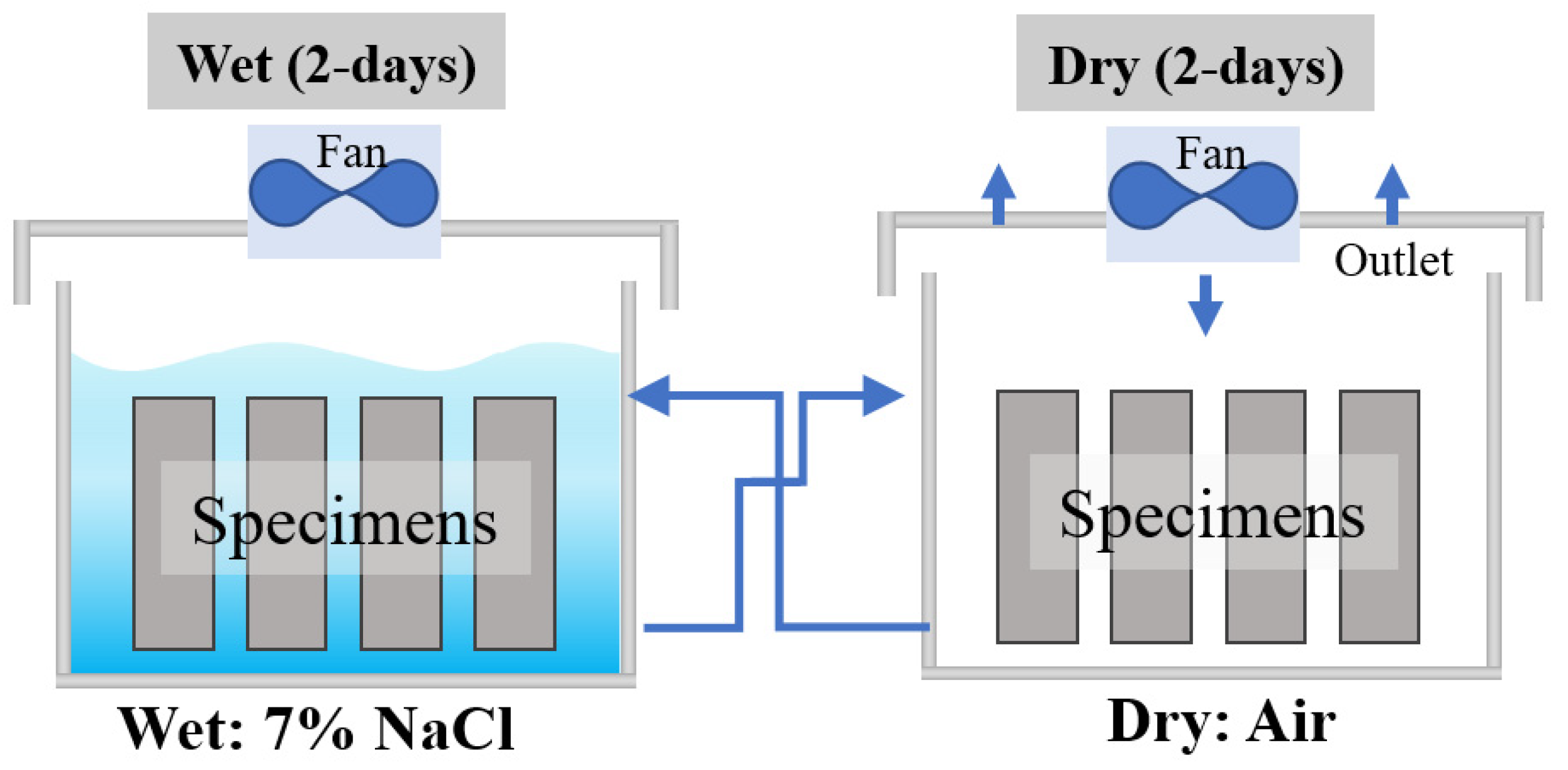
2.1. Chloride Ion Diffusion Method

The essence of diffusion is the movement of chloride ions in SFRC under the influence of a chemical potential gradient (i.e., a concentration gradient). The ion diffusion method can be classified into steady-state diffusion and non-steady-state diffusion based on whether the migration rate of chloride ions in SFRC reaches equilibrium. Due to the complex pore structure and heterogeneity of SFRC, the conditions for achieving steady-state diffusion testing are stringent [49]. Therefore, the application of non-steady-state diffusion methods is more widespread, such as drying–wetting cycles [50] and temperature gradient acceleration methods [51,52,53].
Dry–wet cycling has been proven to be one of the effective methods for accelerating corrosion damage in SFRC, commonly including the salt spray wet–dry cycle method and soaking wet–dry cycle method [54]. The soaking wet–dry cycle method focuses more on the deep penetration of chlorides, while the salt spray wet–dry cycle method emphasizes the corrosion and reactions occurring on the surface of SFRC through periodic spraying of salt mist. The drying phase facilitates the supply of oxygen and the deposition of salts on SFRC, further exacerbating the corrosion of steel fibers. Therefore, both methods can accelerate the corrosion process of steel fibers within a short time, allowing for quick assessment results [55]. It is recommended to select appropriate testing methods based on the corrosion sources and testing objectives of the lining structures in different locations of subsea tunnels. For example, the SFRC lining in the entrance and exit areas of subsea tunnels is constantly exposed to salt mist and marine climate influences, and the closer the tunnel is to the ocean, the more pronounced the effects of the highly corrosive salt mist environment [56]. In this case, it is appropriate to choose the salt spray wet–dry cycle method to explore its chloride corrosion resistance mechanisms. However, when using the salt spray wet–dry cycle method to study the long-term corrosion resistance of SFRC (greater than 2 weeks), attention must be paid to the periodic concentration changes in the corrosion solution caused by evaporation [30].
The soaking wet–dry cycle method also plays a positive role in accelerating the corrosion process. For example, in a comparative study of SFRC exposed for 27 months, specimens treated with the soaking wet–dry cycle method exhibited significantly greater corrosion than those simply immersed in saltwater, resulting in severe corrosion of the steel fibers and slight spalling of the concrete [14]. Given the need to frequently change the wet–dry states of a large number of SFRC specimens over an extended testing period, an automated control system becomes essential. In a two-year SFRC wet–dry cycling experiment, researchers utilized an intelligent control system to conduct comparative studies on influencing factors such as crack width and corrosion solution concentration, accurately controlling the wet–dry state switching of up to 420 specimens, thereby enhancing the reliability of the experimental data [57]. Figure 1 is a schematic diagram of the wet–dry cycle system used in this study. The exposure setup consists of multiple polyethylene containers, each with a capacity of 1 m3, arranged in pairs to create wet–dry cycle conditions. Each pair was interconnected by two membrane pumps, which circulated the solution between the containers. During the wet cycle, the solution was pumped into one container, submerging the specimens in approximately 20 cm of liquid, while the specimens in the other container remained in the dry cycle. The cycles were automatically controlled by an electronic system. Approximately 500 L of exposure solution was circulated at a flow rate of 4.5 L/min.
The experimental results (Figure 2) show that during the soaking wet–dry cycle, under the same conditions, a higher concentration of sodium chloride solution results in a greater density of severely corroded steel fibers. The contour lines in Figure 2 represent the density of 10 steel fibers per square decimeter. The degree of corrosion of the steel fibers is distinguished by the presence or absence of cross-sectional loss [58], with the red dashed line indicating the side of the sample exposed to the corrosive environment. It can be observed that, in addition to the corrosion solution concentration directly increasing the distribution range of corroded steel fibers, the crack width of SFRC specimens also influences the distribution of corroded steel fibers. When the sodium chloride solution concentration is 7%, the distribution range of steel fibers with moderate and severe corrosion is significantly expanded in specimens with a crack width of 0.3 mm.
Furthermore, the temperature difference acceleration method effectively accelerates the corrosion of steel fibers in concrete through high temperatures or freezing [53], making it particularly suitable for the corrosion resistance testing of SFRC structures under extreme climatic conditions. First, in the high-temperature acceleration method, according to the theory of chemical reaction rates, an increase in temperature raises the kinetic energy of the reactants, thereby accelerating the rate of chemical reactions. During the corrosion process, high temperatures can accelerate the reactions between steel fibers and chloride ions or other corrosive substances, leading to an increased corrosion rate. At high temperatures, the rate of water evaporation increases, resulting in higher moisture and salt concentrations in the concrete, which accelerates the diffusion of chloride ions. Additionally, temperature changes can affect the solubility of chloride ions in water, further promoting their corrosion of steel fibers. Second, the principle of freezing acceleration corrosion differs from that of high-temperature acceleration. Low temperatures can cause moisture within the concrete to form ice crystals, thereby altering the properties of the fiber–concrete matrix interface [59]. During the thawing process, the water formed by melting ice crystals can quickly wet the steel fibers, leading to the rapid migration of corrosive substances such as chloride ions. Certainly, a commonality between the two methods is that temperature changes cause different thermal expansions and contractions in the concrete and steel fibers, leading to microcracks that further increase the penetration pathways for corrosive media and accelerate the corrosion of steel fibers [60].
In summary, the selection of the ion diffusion method should closely align with the representativeness of the corrosive environment and the requirements for experimental efficiency. Future directions include the following: (1) implementing advanced multi-dimensional data monitoring technologies to enable real-time monitoring of experimental processes, reduce human error, and improve the repeatability and reliability of experiments; (2) establishing and refining experimental standards and protocols for non-steady-state diffusion methods to enhance the comparability and consistency of results, providing a solid basis for assessing the chloride resistance of SFRC; and (3) developing testing devices capable of simulating multiple environmental factors simultaneously to more comprehensively assess the performance of SFRC under complex condition.

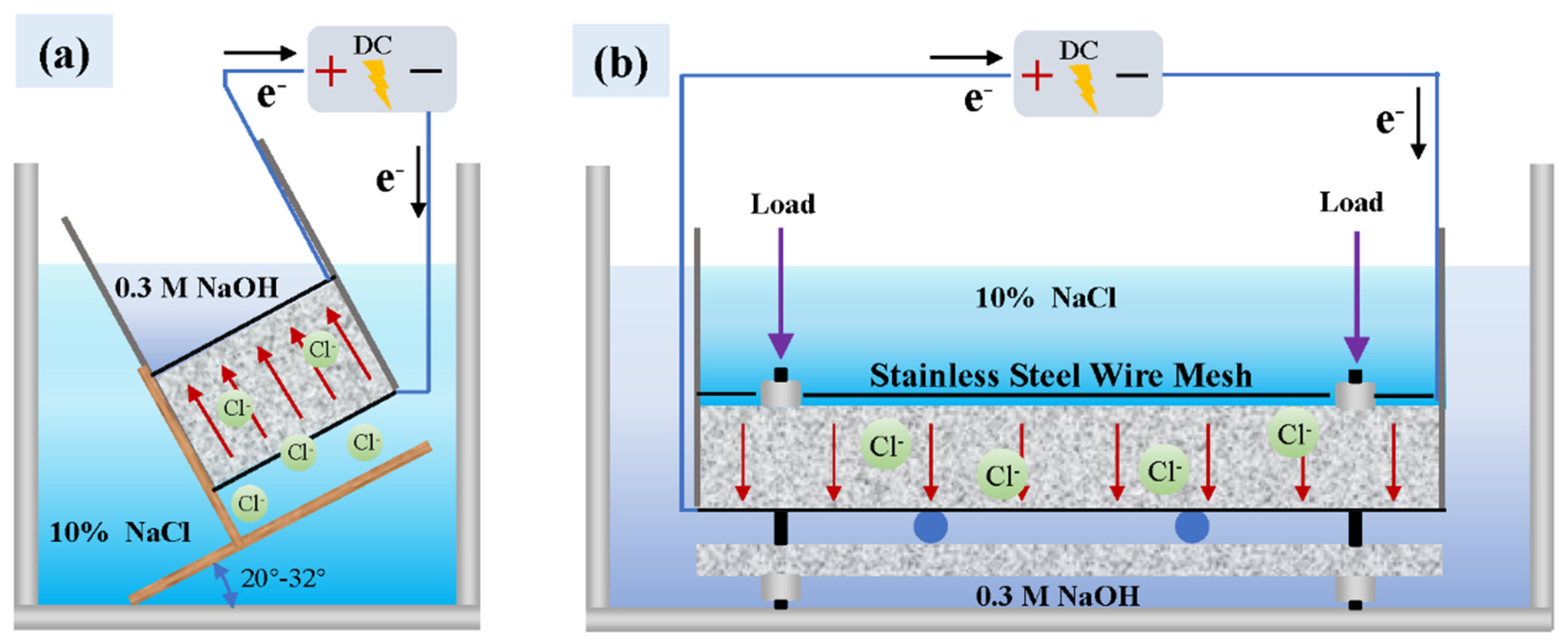
2.2. External Electric Field Migration Method

The external electric field migration method, based on electrochemical principles, has been widely used in the rapid corrosion testing of reinforced concrete structures [61]. Chloride ions are driven by the electric field, which results in a faster corrosion rate for the external electric field migration method compared to the ion diffusion method mentioned in Section 2.1. Such methods can flexibly adjust experimental parameters, including specimen size, corrosion current density, electrolyte solution concentration, acceleration time, and external loads [62,63]. A common effective setup for the external electric field migration method is to connect the rebar under test as the working electrode to the positive terminal of a DC power supply, while using inert materials like stainless steel as auxiliary electrodes to help maintain experimental conditions [64]. Additionally, a reference electrode can be set up to calculate corrosion rates and other electrochemical properties, such as a saturated calomel electrode or a standard hydrogen electrode [65]. However, during the testing of SFRC’s corrosion resistance, the small size of steel fibers relative to rebar, along with their random distribution in concrete, complicates the process. Directly using a single steel fiber as the anode to construct an electrochemical system makes it difficult to achieve ideal experimental results. Therefore, it is necessary to alter the composition of the electrode system when testing SFRC specimens to ensure that the electric field can uniformly cover the entire area to be corroded. Placing one stainless-steel or other-inert-material electrode at each end of the specimen helps optimize current distribution and ensures a more uniform application of the external electric field during testing.
The specific experimental design is based on the rapid test method for the chloride ion migration coefficient in concrete proposed by Tang Luping et al. [66,67], utilizing an external electric field to overcome the binding effect of chloride ions in concrete [68,69]. The CTH method requires only a few hours or days to obtain effective data [70]. Moreover, comparative tests have shown that, except for high water-to-cement ratio concrete samples (>0.5), the chloride ion diffusion coefficients obtained from the soaking diffusion method and the external electric field migration method are generally consistent. Consequently, the improved testing protocol based on this method has been adopted by several countries, including Switzerland, Germany, and China, and has been included in concrete durability testing standards [71,72]. Figure 3 shows two typical experimental setups for the external electric field migration method for SFRC, suitable for cylindrical specimens and beam specimens, respectively. The anode and cathode plates are made of stainless steel, with NaOH solution as the anolyte and NaCl solution as the catholyte. The primary corrosion medium is NaCl solution, and as shown in Table 1, the commonly used solution concentrations range from 3.5% to 23%. A potential difference is established between the external anode and cathode to allow chloride ions to rapidly penetrate the SFRC.
The selection of experimental parameters for the external electric field migration method directly determines the corrosion behavior of steel fibers in SFRC, with key parameters including potential difference, electrification time, and catholyte concentration [66]. (1) Potential difference: A higher potential can facilitate faster testing, but an excessively high potential difference may induce electrolysis, resulting in gas bubbles and other byproducts that interfere with experimental results. On the other hand, a lower potential difference may fail to effectively overcome the electrostatic constraints within the concrete, negatively affecting the migration of chloride ions. (2) Electrification time: An excessively long electrification time may lead to the accumulation of electrolysis products on the specimen’s surface, thereby reducing the subsequent migration efficiency of chloride ions. (3) Catholyte concentration: A highly concentrated chloride ion solution can accelerate the corrosion rate, but it may also create localized concentration gradients. A low concentration chloride ion solution may be insufficient to effectively drive the migration of chloride ions, resulting in minimal corrosion impact on the steel fibers. For example, a case study showed that applying a potential difference of 30 V for 72 h resulted in only partial corrosion of the steel fibers, which did not significantly affect the radial compressive tensile strength of the specimen. However, when the potential difference was increased to 45 V, noticeable cross-sectional loss of the fibers occurred, leading directly to a change in the failure mode. The microcracks formed by the deterioration of the steel fibers caused damage to the surrounding concrete matrix, resulting in a 44% reduction in radial compressive tensile strength [39].
The external electric field migration method has a higher corrosion efficiency compared to the ion diffusion method, significantly shortening the corrosion cycle. It is essential to closely align with the representativeness of the corrosion environment and the requirements for experimental efficiency. Future research directions include the following: (1) although the acceleration of long-term behavior through an externally applied electric field provides some reference, the relationship between short-term accelerated corrosion tests of SFRC and long-term degradation behavior, due to the conductivity of steel fibers, requires further investigation [73]; (2) the development of externally applied electric field migration testing devices with coupled environmental simulation capabilities will be helpful for understanding SFRC corrosion behavior under different environmental factors (such as high water pressure, low temperatures, and tidal effects); and (3) optimizing and improving the electrode configuration, layout, and shape to enhance the stability of the externally applied electric field will ensure a more realistic and controllable migration process of chloride ions in SFRC.

2.3. Pre-Corrosion Method

The pre-corrosion method typically utilizes steel fibers that have already corroded to a certain extent to create specimens for mechanical performance testing, in order to assess the degradation effects induced by different levels of corrosion. The pre-corrosion method offers strong control, allowing for precise regulation of corrosion time and extent, enabling the creation of steel fiber specimens at different corrosion levels for systematic comparative studies [74]. Additionally, it allows for a direct assessment of the impact of corrosion on the mechanical properties of steel fibers, providing reliable experimental data and conclusions. Especially for bending or tensile components in subsea tunnels, the overall performance of the SFRC lining structure largely depends on the mechanical behavior of steel fibers, and the toughness of the lining components primarily relies on the pull-out behavior of individual fibers. Investigating the effect of different corrosion levels of steel fibers on the mechanical properties of SFRC is essential [58]. However, an unavoidable issue is that the corrosion behavior observed under laboratory conditions may differ significantly from the corrosion processes in real environments, making it difficult to accurately simulate the actual degradation processes of SFRC.
Furthermore, some researchers have suggested adding chlorides to concrete mixtures to observe the corrosion behavior of steel fibers, and these findings provide new directions for the application of chloride additives in SFRC technology. Curing SFRC samples in chloride solutions or incorporating chlorides into the mixture can lead to severe pitting damage in the fibers, significantly reducing their pull-out resistance [45]. This underscores the importance of isolating SFRC from seawater during the curing process at construction sites of cast-in-place structures in subsea tunnels. However, when used to study the deterioration mechanisms of steel fibers, the migration and diffusion of chlorides within concrete are difficult to control precisely, potentially leading to uncertainties in the experimental results. In summary, the pre-corrosion method offers a high degree of control and the possibility for direct observation, but it has limitations in simulating real marine erosion environments.

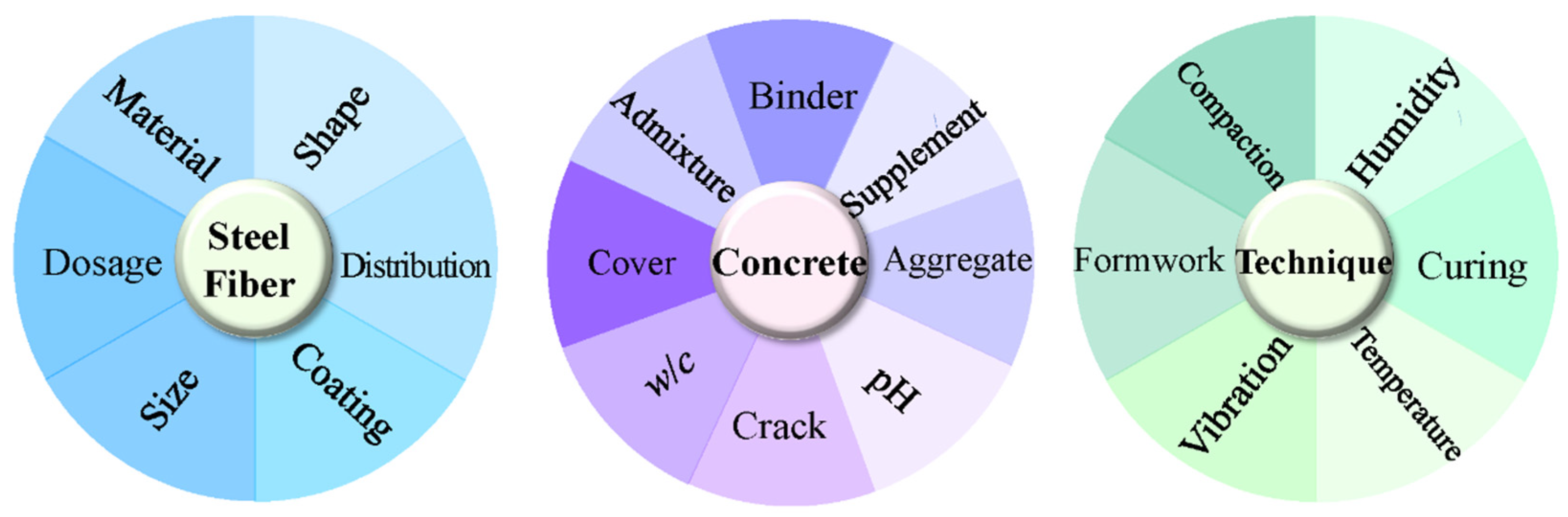
3. The Influence of Steel Fibers on the Chloride Corrosion Resistance of SFRC

In recent years, researchers have conducted extensive studies on the factors affecting the chloride corrosion resistance and long-term durability of SFRC, evolving from single-factor analysis to considering multi-factor coupling effects [75]. As shown in Figure 4, the influencing factors are categorized based on steel fiber, concrete matrix, and on-site construction processes. First, the influencing factors related to steel fibers include material, size, shape, distribution, coating, and dosage. Second, various factors of the concrete matrix also affect the chloride corrosion resistance of SFRC. For example, the impact of crack width in the concrete matrix on chloride resistance has been discussed in Section 2.1. In addition, the cover layer, which is the outermost part of the concrete from the surface to the steel fibers, directly affects the penetration path of chloride ions. As the cover layer thickness increases, chloride ions require more time to reach the steel fibers, thereby delaying corrosion. Furthermore, a thicker cover layer helps slow down the ingress of oxygen and moisture, further reducing the corrosion rate of steel fibers. However, an excessively thick cover layer may increase the risk of concrete cracking, affecting long-term durability. The water-to-cement ratio (w/c) determines the porosity and permeability of concrete [39]. A lower w/c typically reduces porosity and increases the density of concrete, thereby decreasing the chloride ion diffusion rate and enhancing chloride corrosion resistance. Conversely, a higher w/c results in more interconnected pores, facilitating chloride ion penetration and making steel fibers more susceptible to corrosion. Therefore, to improve durability, it is essential to optimize the w/c, ensuring sufficient workability while maintaining good compactness. Finally, the construction techniques of SFRC on-site are also crucial factors that require careful consideration. For instance, high-quality formwork can reduce bleeding and shrinkage cracks during concrete casting, ensuring surface density and thereby reducing chloride ion penetration risks. Smooth and dense formwork enhances the quality of the concrete surface, minimizing surface microcracks and further improving chloride corrosion resistance [41]. Moreover, appropriate curing temperature and humidity facilitate complete cement hydration, increasing concrete density and reducing porosity, thus lowering chloride ion penetration rates. Although high curing temperatures can accelerate early strength development, they may lead to uneven hydration product distribution, forming large pore structures that reduce long-term durability.
This section discusses in detail the mechanisms by which steel fibers influence the chloride corrosion resistance of SFRC, considering factors such as the material, coating, shape, and dosage of the steel fibers.

3.1. Types of Steel Fibers

There is no doubt that the chloride corrosion resistance of SFRC is influenced by the material and alloy composition of the steel fibers [76]. Different countries have established clear classifications for steel fibers based on their raw materials. For example, the standards for steel fibers for concrete released in China categorize them into carbon steel, alloy steel, stainless steel, and other types [77]. Similarly, the classifications advocated by the European Union include cold-drawn carbon steel (including low-, medium-, and high-carbon steel), surface coatings, and stainless steel [78].
Different alloy components in steel fibers, such as nickel, chromium, and manganese, can significantly enhance their corrosion resistance [79]. For instance, a study exposing SFRC to a beach environment and subjecting it to 2000 wet–dry cycles indicated that stainless-steel fibers (with nickel and chromium contents of 0.58% and 17.6%, respectively) showed no signs of corrosion when exposed on the concrete surface. However, under the same exposure conditions, low-carbon steel fibers (with nickel and chromium contents of 0.06% and 0.04%, respectively) experienced corrosion after 150 wet–dry cycles, which gradually progressed to widespread corrosion [35]. Therefore, steel fibers with higher carbon content are generally more susceptible to corrosion, while micro-alloying elements such as vanadium and titanium can enhance their corrosion resistance and strength. Furthermore, studies have shown that the addition of manganese effectively improves the corrosion resistance of the alloy. The depth of corrosion products is reduced with manganese addition. The primary reason for the enhanced corrosion resistance is the formation of an oxide film that inhibits chloride ion penetration [80]. However, due to the strong affinity between manganese and sulfur, the formation of manganese sulfide often leads to a decline in the pitting and crevice corrosion resistance of austenitic stainless steel in chloride environments. The crystalline structure of the material (such as martensite or austenite) also affects the corrosion resistance of steel fibers [81]. Austenitic stainless steels typically have higher chromium and nickel content, which allows for the formation of more stable passive films, enhancing their resistance to pitting corrosion. In contrast, martensitic stainless steels have lower chromium content and generally contain little or no nickel, making their passive films more prone to breakdown.
On the other hand, the surface condition of the steel fibers is crucial, as processes such as heat treatment and cold working can influence their corrosion resistance. For example, the cold drawing process creates a more uniform surface on the steel fibers, thereby suppressing the occurrence of pitting. In summary, the material and compositional factors of steel fibers jointly determine their performance in marine corrosion environments, which in turn affects the overall chloride corrosion resistance of SFRC.

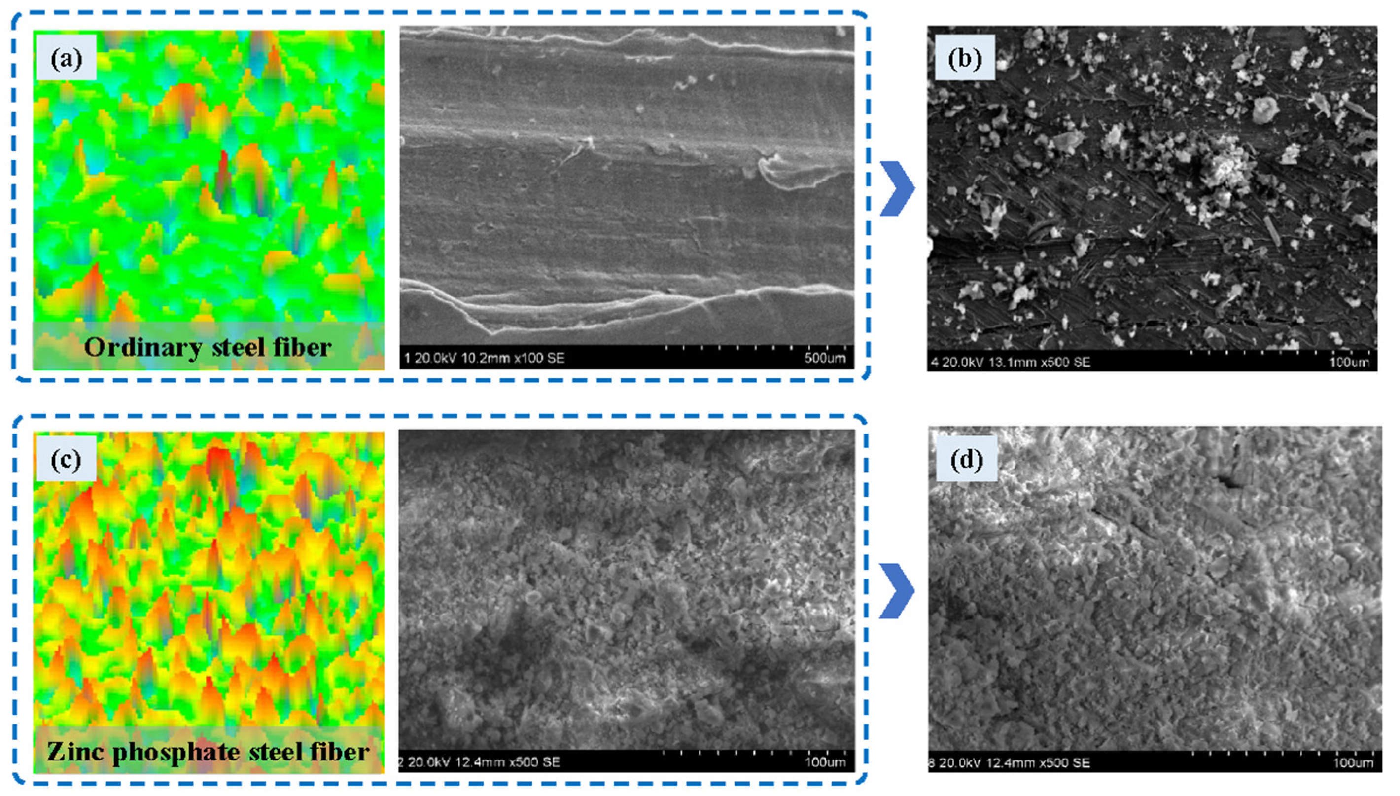
3.2. Surface Coatings for Steel Fibers

The use of anti-corrosion coatings can effectively enhance the corrosion resistance of steel fibers to a certain extent [82,83]. For example, a zinc phosphate coating [84] improves the corrosion potential and reduces the corrosion rate of steel by consuming the zinc coating during the anodic process. The coating exhibits strong resistance to various chemicals (such as chloride ions), thereby providing more stable protection in marine corrosion environments. As shown in Figure 5a,b, the surface of ordinary steel fibers is relatively flat with minor undulations, whereas the surface of zinc phosphate-coated steel fibers exhibits noticeable undulations and a distinct conical structure, with particles arranged more closely. After undergoing 30 wet–dry cycles of corrosion, the zinc phosphate-coated steel fibers, while avoiding the occurrence of microcracks, showed little overall change in surface morphology, with the surface becoming rougher [48]. This also provides evidence that zinc phosphate-coated steel fibers can protect the fiber matrix from corrosion and maintain good bonding performance with concrete. Similar studies have shown that after 15 corrosion cycles, the loss of bonding strength in zinc phosphate-coated fibers is negligible compared to that of ordinary steel fibers [85].
Additionally, some researchers have attempted to use graphene oxide-coated steel fibers to improve the interface transition zone and enhance the overall performance of SFRC [86]. The results show that the surface roughness and hydrophilicity of the graphene oxide-coated steel fibers treated with a three-step coating method increased by approximately 280.6% and 40.6%, respectively. At the same time, graphene oxide-coated steel fibers can significantly reduce the porosity of SFRC and optimize the pore size distribution, which will improve its resistance to chloride ion corrosion. Recently, researchers have focused on the surface modification of steel fibers using nanomaterials. The latest studies suggest that nano-SiO2 is a promising coating material for steel fibers because it can react with Ca(OH)2 to form calcium silicate hydrate (C-S-H), effectively improving the adhesion between the steel fibers and the cement matrix. The use of these coating materials greatly contributes to enhancing SFRC’s resistance to both load and environmental corrosion [87].
The bond strength between the coating and steel fibers is a key issue. Different types of coating materials may exhibit variations in their adhesion to the surface of the steel fibers. Inadequate adhesion of the coating could lead to delamination or peeling, which in turn affects the mechanical properties and durability of the concrete. Additionally, ensuring that the coating is uniformly applied to all steel fibers without any omissions remains a technical challenge. The uniformity of the coating is crucial for the performance of the steel fibers in the concrete, as uneven coatings may result in instability in the concrete’s strength and corrosion resistance. Reference [86] compared three different steel fiber coating methods and showed that some coating methods negatively affect the microstructure of SFRC. The standardized coating specifications for steel fiber surface modification have not yet been established. Some literature indicates that while the use of coatings prolongs the initiation time of corrosion in the steel matrix, unfortunately, it cannot prevent the development of corrosion over long periods in corrosive environments. Therefore, once the coating is removed due to local damage or large strain in the steel, conditions for electrochemical corrosion reactions are established, particularly in the presence of electrolytes, where localized anodic and cathodic reactions may become more pronounced, leading to an accelerated corrosion rate.

3.3. Shape of Steel Fibers

To enhance anchoring strength and bonding with the concrete matrix, the ends of steel fibers are typically designed to be hook-shaped, corrugated [88], or conical [43]. The importance of using shaped steel fibers in providing superior pull-out resistance has been well recognized compared to straight steel fibers [58]. Especially, the hooked design facilitates the use and placement of steel fibers during manufacturing and handling, allowing for more uniform dispersion in concrete. Therefore, hooked-end fibers are the most widely studied and applied (Table 1).
However, researchers have found that the bends and ends of hook-shaped steel fibers in the concrete matrix are more susceptible to chloride-induced corrosion. As shown in Figure 6, there are three main reasons: On the one hand, the hook structure creates stress concentrations at the bends and ends, where mechanical stress is higher, leading to the formation of micro-defects that allow corrosive media to penetrate more easily, resulting in preferential anodic pitting and accumulation of corrosion products [89]. On the other hand, under load, the contact between the concrete matrix and the steel fibers may fail, creating gaps that facilitate the penetration of moisture, chloride ions, and other corrosive media [42]. Finally, the damaged interfacial transition zone provides a preferential pathway for the transport of chlorides, metal ions, and oxygen, thereby accelerating the corrosion process [90].

3.4. Dosage of Steel Fibers

A substantial body of literature indicates that SFRC exhibits different dosage thresholds for various performance indicators, such as tensile strength, shrinkage strain, and thermal conductivity [91,92,93]. When designing concrete mix proportions, it is essential to consider the balance among different performance characteristics [94]. There is also a dosage threshold for steel fibers concerning the performance indicators for resisting chloride corrosion. Below this threshold, an increase in fiber dosage optimizes the pore structure of SFRC, as the dispersed steel fibers disrupt the continuity of pores and the interconnectivity of porous channels within the concrete matrix. As the steel fiber dosage increases, the proportion of closed pores within the total porosity also increases [91]. Conversely, above the threshold, the porosity increases with fiber dosage, leading to the degradation of the concrete’s pore structure, which negatively impacts its resistance to chloride ion corrosion [95]. Moreover, a high dosage of steel fibers, particularly those with irregular ends, tends to agglomerate, forming “bridging” or “layering” structures that further deteriorate the pore structure. Certainly, the steel fiber dosage threshold is characteristic and dependent on factors such as environmental conditions, concrete components, and other material properties. For instance, results from a case study [40] indicate that the volume fraction threshold for the durability of SFRC is 1.5%. Similarly, a case study [96] analyzed the mapping relationship between the pore structure of SFRC and steel fiber dosage using mercury intrusion porosimetry and scanning electron microscopy, showing that when the steel fiber dosage increased from 1.5% to 2%, the number of large pores in the concrete significantly increased. Research under the coupled conditions of salt freeze–thaw and wet–dry cycles indicates that 2% is the dosage threshold for changes in porosity induced by SFRC [53].
Furthermore, excessive use of steel fibers may lead to a decrease in the workability and constructability of concrete, increasing construction costs. In the design process of subsea tunnel structures, reasonably determining the dosage threshold helps ensure optimal performance, and different thresholds may be required for SFRC components under various uses and environmental conditions. Certainly, the above conclusions are based on the assumption of a uniform distribution of steel fibers; excessive fiber dosage can lead to non-uniform fiber density, which weakens the structure’s resistance to chloride corrosion, with areas of the lowest and highest initial fiber density being most susceptible to surface damage [53].

4. Application and Challenges of SFRC in Subsea Tunnel Engineering

SFRC possesses excellent mechanical properties, such as (1) higher toughness; (2) effective suppression of crack growth or propagation within the concrete; (3) improved impact resistance; and (4) higher residual strength, making it widely used in terrestrial tunnel engineering [97,98,99]. In recent years, SFRC has also shown promising applications in the prefabricated concrete segment structures of subsea tunnel engineering due to its excellent corrosion resistance. With the advancement of technology and deeper research, the application of SFRC in this field is expected to become even more widespread.

4.1. SFRC Application Cases in Subsea Tunnels

The main application areas of SFRC in subsea tunnel engineering include initial support, cast-in-place linings, prefabricated segments, and auxiliary structures (such as ventilation shafts and drainage ditches). Table 2 lists typical application cases. Norway was one of the first countries to use steel fiber shotcrete technology for constructing subsea tunnels. According to statistics, the average amount of steel fiber shotcrete used in 17 subsea road tunnels constructed in Norway from 1983 to 1999 was approximately 1.1 m3/m, while the amount of SFRC used in the Nordkapp Tunnel was about 4 m3/m [100]. With the in-depth research on the corrosion resistance of SFRC and the development of shield tunneling technology, the application areas of SFRC have expanded from shotcrete support to prefabricated concrete segments. For example, the Metro Doha Green Line utilized 40 kg/m3 of low-carbon cold-drawn steel fibers in the segments to meet stringent corrosion environments (with a maximum chloride concentration of 55,000 mg/L) and a durability requirement of 120 years [101].

4.2. Challenges in the Application of SFRC in Subsea Tunnel Engineering

Figure 4 lists common factors in the typical construction processes of tunnels that may affect the corrosion resistance of steel fiber-reinforced concrete, such as curing temperature and humidity, the type of lining formwork, and vibration methods. However, the construction environment of subsea tunnel linings is different from that of ordinary tunnels. This section summarizes the challenges encountered in the application of steel fiber-reinforced concrete in subsea tunnel projects, as well as the issues that require further research, based on the actual construction characteristics of subsea tunnel engineering.

4.2.1. Multi-Directionality of Chloride Corrosion

Unlike the artificially created, directional corrosion environments used in laboratory tests, the chloride corrosion direction in actual subsea tunnel lining structures is multidirectional, especially in composite lining systems. For instance, a study conducted on SFRC used in the Nordkapp Tunnel 20 years’ post-installation [100] revealed significant anisotropy in chloride distribution in core samples obtained from different locations. μ-XRF analysis of the extracted shotcrete (Figure 7) indicated that chloride diffusion in core sample 1 occurred from the outer surface of the lining toward the rock substrate, while core sample 2 exhibited the opposite trend. In long-term immersion conditions (ranging from several years to decades), the corrosion products in steel fiber-reinforced concrete in a seawater environment will progressively evolve with the increasing degree of corrosion and environmental ion exchange. Medium- to long-term products include α-FeOOH, β-FeOOH, and γ-FeOOH. Over time, FeOOH gradually loses moisture and forms more stable Fe2O3 and Fe3O4.
The direction of chloride diffusion within the concrete is uncertain and influenced by factors such as drainage systems, tidal fluctuations, and environmental conditions. The evolution of the seepage field surrounding the subsea tunnel, coupled with tidal changes, can cause chloride diffusion to occur in varying directions, which, in turn, affects the distribution of chlorides within the concrete [106]. This multi-directionality results in a complex chloride distribution pattern, where some areas may experience higher chloride concentrations, while others may have lower levels. Such variability complicates the accuracy of non-destructive testing methods and poses challenges for long-term predictions of chloride concentrations.
Additionally, due to the random distribution and smaller size of steel fibers, detecting the corrosion state of these fibers becomes more challenging compared to the larger steel reinforcements used in traditional tunnel linings, especially under the influence of multidirectional chloride corrosion. As discussed earlier, the chloride corrosion direction in subsea tunnel linings is multidirectional, driven by factors such as tidal fluctuations and changes in the surrounding seepage field. This results in corrosion occurring in different locations and at varying times, making it more difficult to track the progression of corrosion, particularly in localized areas. The corrosion of steel fibers may therefore occur irregularly, complicating detection and leading to inconsistencies in the results. Conventional detection methods, which are often designed for more predictable and uniform corrosion patterns, may fail to effectively capture these subtle, complex changes in the corrosion state of steel fibers. This limitation directly impacts the accurate assessment of the overall structural durability of subsea tunnel linings [107,108]. Consequently, there is an urgent need to develop more advanced monitoring technologies and methodologies to better understand the corrosion behavior of steel fibers and the movement of chlorides within the concrete.

4.2.2. Diversity of Chloride Sources for Corrosion

Seawater penetrates through chloride ions to damage the passive film of reinforcing steel or steel fibers, leading to the occurrence of corrosion reactions. Particularly, when the chloride ion concentration exceeds the critical threshold, the corrosion risk of reinforcing steel or steel fibers significantly increases. In addition to chloride ions, other chemical components in seawater, such as dissolved oxygen, carbon dioxide, and sulfate, also accelerate the corrosion process. The electrochemical corrosion process generates rust, leading to crack propagation and penetration, thereby affecting the durability of concrete. In actual subsea tunnel engineering, the sources of chlorides are diverse. Chlorides from different sources can have varying chemical properties and concentrations, affecting the electrochemical environment of concrete, altering the polarization behavior of steel fibers, and subsequently influencing the corrosion mechanisms. This leads to different corrosion behaviors of steel fibers. The diffusion behaviors, binding capacities, corrosion products, and deterioration patterns of different types of chlorides (such as NaCl, KCl, CaCl2, and MgCl2) vary [109,110]. Further research should delve into the coupling effects of various chlorides on the corrosion behavior of steel fibers and the degradation mechanisms of lining structures.
De-icing salts, seawater leaking from rock seams (Figure 8), and sea salt spray are common corrosion sources in studies [111]. While the sources of chloride corrosion during the operational phase of subsea tunnels have been comprehensively studied, chloride corrosion during the construction phase has received little attention. To avoid significant geological disasters, comprehensive geological forecasting before excavation at the tunnel face is crucial [112,113]. For example, the second subsea tunnel in Jiaozhou Bay currently under construction in China employs advanced drilling techniques for geological forecasting before excavation. As shown in Figure 8, when drilling exposes water in front of the tunnel face, seawater can gush out along the borehole, with a maximum water flow rate of 800 L/min per borehole. Subsequently, the concrete support structure behind the tunnel face can be directly scoured, splashed, or even soaked by corrosive media. This is especially serious if the concrete is still in the curing phase and the matrix has not yet achieved adequate impermeability, as the corrosion sources during construction can lead to more severe durability deterioration. Therefore, greater emphasis should be placed on identifying the sources of corrosion during construction, and practical guidelines should be established to ensure that corrosion protection is integrated throughout the construction process.

4.2.3. Non-Uniform Distribution of Steel Fibers

The spatial variability of steel fiber distribution affects not only the mechanical response but also the structural corrosion resistance and long-term durability [114,115]. Numerous aspects of the subsea tunnel construction process can lead to defects in steel fiber distribution, resulting in decreased local density of the concrete and affecting chloride intrusion behavior. The main influencing factors include the following: (1) Concrete pouring methods: Different pouring techniques (such as pumping, gravity pouring, etc.) may lead to uneven distribution of steel fibers in the concrete, especially in the complex construction environment of subsea tunnels. As the span of subsea tunnel excavation increases, the section-by-section excavation method divides the large tunnel cross-section into smaller sections for separate construction [116]. Therefore, as shown in Figure 9, due to the limited working space in subsea tunnels, concrete pouring methods often use specialized mechanical pumping or chutes for delivery. The delivery distance, pipe design, flow control, and pouring speed of different pouring methods may cause the aggregation or separation of steel fibers during transport, ultimately affecting their distribution [117]. (2) Vibration methods. The vibration method for the subsea tunnel lining is influenced by structural geometric features, making it difficult to use surface-mounted vibrators exclusively; localized vibration often relies on manual insertion of vibrators, where the effectiveness largely depends on the skill of the workers, increasing the likelihood of uneven steel fiber distribution. Additionally, uneven or insufficient vibration may cause the aggregation or absence of steel fibers in certain areas, thereby affecting overall performance.
Certainly, from another perspective, it is worthwhile to explore the intentional creation of spatial variations in steel fiber distribution based on the structural differences in subsea tunnels. For example, in areas expected to bear large loads (such as the tunnel crown and shoulder), the fiber content can be increased to enhance the tensile strength and crack resistance of these sections. At the junctions of different materials or structures (such as the interface between concrete and other structural materials), the distribution of steel fibers can be optimized to improve the effectiveness of stress transfer and reduce the potential risks associated with stress concentration.

4.2.4. Complexity of the Tunnel Service Environment

The service environment of subsea tunnels is more complex than that of mountain tunnels, encompassing numerous factors that further influence the performance and longevity of SFRC linings. These factors include, but are not limited to, geological conditions, hydrological characteristics, temperature fluctuations, water pressure variations, and chemical exposures [118,119]. The interaction of these elements creates a dynamic and often harsh environment, posing significant challenges to the structural integrity and durability of tunnel materials. Understanding and mitigating the effects of this complex environment are crucial for ensuring the safe and reliable operation of subsea tunnels throughout their service life. An important factor influencing the corrosion rate of steel fibers in the SFRC linings of subsea tunnels, for example, is temperature. Given the significant variation in environmental temperature throughout the service life of tunnels, the effects of curing temperature and environmental temperature fluctuations during the service period on the durability of SFRC warrant careful consideration. In addition to influencing the corrosion rate, temperature also affects the density, crystallinity, and composition of hydration products [120]. Furthermore, the temperature of the subsea environment plays a crucial role in determining the characteristics of the interfacial zone between steel fibers and the matrix, as well as the bond strength.
It is worth noting that SFRC linings exhibit relatively high electrical conductivity, which provides a leakage path for stray currents [121]. While the short-term effects of stray currents on steel fibers are limited, their combined action with chloride ions in seawater can accelerate the initiation of pitting corrosion on the surface of steel fibers [122].

4.3. The Fabrication, Industrial Testing, and Market Share of SFRC in Subsea Tunnel Engineering

A large amount of SFRC is required in the construction of subsea tunnel linings, and the standardization of its manufacturing process can have a potential impact on its corrosion resistance. The commonly used mixing methods for steel fiber-reinforced concrete include two approaches: one is to dry-mix the steel fibers, coarse and fine aggregates, and cement and then add water for wet mixing; the other is to uniformly distribute the steel fibers during the mixing process [123,124]. When the steel fiber content is high, the mixing time should be appropriately extended. A key research focus in the future will be how to effectively prevent steel fiber clumping during the mixing process [125]. Before SFRC is used in construction sites, it needs to undergo tests including workability, mechanical properties, and long-term durability performance [126,127]. Table 3 lists the common testing items for SFRC. By optimizing the SFRC manufacturing process and strictly conducting performance tests, the corrosion resistance of SFRC can be effectively improved, extending its service life in extreme environments.
In the past two decades, with the publication of many design guidelines and standards, the use of steel fibers as a partial or full replacement for traditional reinforcement materials has gained increasing consideration [14,98]. This indicates that the market share of commercial SFRC is expected to experience significant growth in the future. At the same time, with the global increase in demand for sustainable building materials, the use of SFRC made with recycled steel fibers will become an important trend in the future construction industry. Many countries and regions have implemented strict environmental policies, promoting waste recycling and the use of recycled resources. For example, producing steel fibers by recycling steel wires from used tires can significantly reduce production costs, providing companies with a competitive economic advantage [128]. This is particularly true in the context of rising raw material prices, where recycled steel fibers present a more attractive option [129]. In the future, SFRC will become an important material that aligns with sustainable development goals, and market demand is expected to further grow.

5. Conclusions and Recommendations

This paper compares three types of indoor test methods for studying chloride-induced corrosion of SFRC and explores the mechanisms by which the material, coating, shape, and dosage of steel fibers affect the chloride corrosion resistance of SFRC. Additionally, based on practical application cases of SFRC in subsea tunnels, challenges and unresolved research questions in its application are presented. The main conclusions are summarized as follows:
(1) The corrosion results obtained from non-steady-state ion diffusion methods, represented by the wet–dry cycle method, are more consistent with actual deterioration patterns, while the applied electric field migration method exhibits a faster corrosion rate compared to the ion diffusion method, effectively shortening the test duration. The pre-corrosion method allows for precise control over the corrosion level of steel fibers, providing the possibility for direct observation; however, it has limitations in replicating the actual corrosion process. The selection of accelerated corrosion test methods should closely align with the representativeness of the corrosion environment, the requirements for testing efficiency, and the test objectives. In the future, high-precision intelligent multi-monitoring equipment should be equipped to achieve automated control of the experimental process. Additionally, developing experimental devices that can simultaneously simulate the combined effects of multiple influencing factors is particularly important for comprehensively revealing the durability of SFRC in complex marine environments. Certainly, further research is needed to explore the relationship between the short-term accelerated corrosion tests of SFRC and the long-term deterioration behavior in actual engineering.
(2) The chloride corrosion resistance of SFRC is influenced by the coupling effects of the material, surface coating, shape, and dosage of steel fibers, which collectively determine its long-term performance in marine corrosive environments. Alloy components such as nickel, chromium, and manganese, along with anti-corrosion coatings, can significantly enhance the corrosion resistance of steel fibers; however, the reliability of these coatings under prolonged corrosive environments requires further investigation. Furthermore, the reasonable determination of the dosage threshold for steel fibers during the design of subsea tunnel structures is crucial for optimizing performance. Focusing on different tunnel components and varying corrosive environments as well as developing multi-objective optimization models that comprehensively consider multiple performance indicators such as tensile strength, compressive strength, and corrosion resistance of steel fibers are of great practical significance.
(3) Unlike the controlled corrosion environments in laboratories, actual subsea tunnel projects face numerous challenges and unresolved issues during both the construction and operational phases. The multi-directionality of chloride erosion, the diversity of erosion sources, and the uneven distribution of steel fibers due to construction practices all pose obstacles to predicting the long-term maintenance costs and structural longevity of subsea tunnel projects. Future efforts should involve interdisciplinary research combining materials science, engineering technology, and environmental science to comprehensively address the complex challenges faced by SFRC in subsea tunnels during both construction and operational phases.

Author Contributions

Conceptualization, J.L. and H.G.; methodology, J.L. and H.G.; validation, Q.C., H.S. and W.P.; formal analysis, H.S., W.P. and M.H.; investigation, J.L. and H.G.; resources, L.W. and H.G.; data curation, J.L. and M.H.; writing—original draft preparation, J.L., L.W., H.G. and Y.X.; writing—review and editing, Q.C., H.S. and W.P.; visualization, H.G. and M.H.; supervision, J.L. and H.G.; project administration, J.L. All authors have read and agreed to the published version of the manuscript.

Funding

This research was funded by the Key Program of CCCC (No. 2024-ZJKJ-04 and No. 2022-ZJKJ-10).

Institutional Review Board Statement

Not applicable.

Informed Consent Statement

Not applicable.

Data Availability Statement

The original contributions presented in this study are included in this article; further inquiries can be directed to the corresponding author.

Conflicts of Interest

Authors Jiguo Liu, Longhai Wei, Qinglong Cui, Heng Shu, Wenbo Peng were employed by the company CCCC Second Highway Consultants Co., Ltd. The remaining authors declare that the research was conducted in the absence of any commercial or financial relationships that could be construed as a potential conflict of interest.

References

  1. Zhang, Y.T.; Wang, M.N.; Yu, L.; Guo, X.H.; Wang, Z.H.; Li, C.H. Experimental and numerical research on the influence of steel arch frame corrosion on security of supporting system in subsea tunnel. Tunn. Undergr. Space Technol. 2022, 120, 16. [Google Scholar] [CrossRef]
  2. Basheer, L.; Kropp, J.; Cleland, D.J. Assessment of the durability of concrete from its permeation properties: A review. Constr. Build. Mater. 2001, 15, 93–103. [Google Scholar] [CrossRef]
  3. Sulikowski, J.; Kozubal, J. The Durability of a Concrete Sewer Pipeline Under Deterioration by Sulphate and Chloride Corrosion. In Proceedings of the 25th Russian-Polish-Slovak Seminar on Theoretical Foundation of Civil Engineering, Zilina, Slovakia, 11–16 July 2016; Elsevier Science Bv: Zilina, Slovakia, 2016; pp. 698–705. [Google Scholar]
  4. Cassiani, J.D.; Dugarte, M.; Arteta, C.A.; Kessler, S. Durability assessment of a tunnel structure with two-sided chloride ingress-A case study located in a tropical environment. Struct. Concr. 2022, 23, 739–752. [Google Scholar] [CrossRef]
  5. Gong, H.M.; Xue, Y.G.; Fu, K.; Kong, F.M.; Han, M.; Zhou, B.H.; Guo, Y.B. Assessing and predicting surrounding rock settlement troughs in the subsea tunnel: A case study of Haicang Tunnel. Mar. Geores. Geotechnol. 2024, 12, 1–12. [Google Scholar] [CrossRef]
  6. Sun, Z.Y.; Zhang, D.L.; Fang, Q. Technologies for large cross-section subsea tunnel construction using drilling and blasting method. Tunn. Undergr. Space Technol. 2023, 141, 15. [Google Scholar] [CrossRef]
  7. Zhou, X.H.; Yang, Y.Y.; Yang, Z.P.; Liu, S.J.; Wang, H.; Zhou, W.F. Theoretical analysis of erosion degradation and safety assessment of submarine shield tunnel segment based on ion erosion. Geomech. Eng. 2024, 37, 599–614. [Google Scholar]
  8. Chen, X.S.; Shen, J. Experimental Investigation on Deterioration Mechanisms of Concrete under Tensile Stress-Chloride Ion-Carbon Dioxide Multiple Corrosion Environment. J. Mar. Sci. Eng. 2022, 10, 80. [Google Scholar] [CrossRef]
  9. Yilmaz, D.; Angst, U. Corrosion Caused Costs on Civil Engineering Structures of the Swiss Road Networks. Beton-Stahlbetonbau 2020, 115, 448–458. [Google Scholar] [CrossRef]
  10. Karacic, S. Microbial Biofilm Communities Associated with Degradation of Sprayed Concrete in Subsea Tunnels; Chalmers Tekniska Hogskola: Gothenburg, Sweden, 2021. [Google Scholar]
  11. Zhang, Z.; Ye, T.; Zhu, Z.; Pan, Y.T.; Wu, Z. Time-varying analysis of deterioration by chloride ion erosion for subsea tunnels under wave loads. Chin. J. Geotech. Eng. 2023, 45, 1323–1332. [Google Scholar]
  12. Abbas, S. Structural and Durability Performance of Precast Segmental Tunnel Linings; The University of Western Ontario: London, ON, Canada, 2014. [Google Scholar]
  13. Gong, C.J.; Ding, W.Q.; Mosalam, K.M.; Günay, S.; Soga, K. Comparison of the structural behavior of reinforced concrete and steel fiber reinforced concrete tunnel segmental joints. Tunn. Undergr. Space Technol. 2017, 68, 38–57. [Google Scholar] [CrossRef]
  14. Kim, B.; Boyd, A.J.; Lee, J.Y. Durability performance of fiber-reinforced concrete in severe environments. J. Compos. Mater. 2011, 45, 2379–2389. [Google Scholar] [CrossRef]
  15. Feng, K.; Pan, J.; Xing, W.J.; Li, M.J.; Geng, J.Y.; He, C. Experimental study on the high water pressure erosion mechanism and its influence on the submarine shield tunnel concrete segments. Constr. Build. Mater. 2023, 408, 19. [Google Scholar] [CrossRef]
  16. Ding, W.T.; Huang, X.H.; Wang, Z.R.; Chen, L. Experimental study on the shear performance of a prestressed anchored jointed rock-like mass under different corrosion levels. Int. J. Rock Mech. Min. Sci. 2022, 158, 15. [Google Scholar] [CrossRef]
  17. Feng, W.P.; Tarakbay, A.; Memon, S.A.; Tang, W.C.; Cui, H.Z. Methods of accelerating chloride-induced corrosion in steel-reinforced concrete: A comparative review. Constr. Build. Mater. 2021, 289, 14. [Google Scholar] [CrossRef]
  18. Tang, K.K. Stray current induced corrosion of steel fibre reinforced concrete. Cem. Concr. Res. 2017, 100, 445–456. [Google Scholar] [CrossRef]
  19. Wang, X.L.; Liu, Y.Q.; Liu, S.Q. Effect of chloride-induced corrosion on bond performance of various steel fibers in cracked SFRC. Cem. Concr. Compos. 2023, 140, 14. [Google Scholar] [CrossRef]
  20. Chen, J.W.; Fu, C.Q.; Ye, H.L.; Jin, X.Y. Corrosion of steel embedded in mortar and concrete under different electrolytic accelerated corrosion methods. Constr. Build. Mater. 2020, 241, 17. [Google Scholar] [CrossRef]
  21. Páez Jiménez, C. Corrosion Durability Service Life of Calcium Silicate-Based Reinforced Concrete. Master’s Thesis, University of South Florida, Tampa, FL, USA, 2021. [Google Scholar]
  22. Berrocal, C.G.; Lundgren, K.; Löfgren, I. Corrosion of steel bars embedded in fibre reinforced concrete under chloride attack: State of the art. Cem. Concr. Res. 2016, 80, 69–85. [Google Scholar] [CrossRef]
  23. He, Z.S.; He, C.; Kang, X.Y.; Huang, X.; Wang, S.M.; Xu, G.W. Effects of sustained load and reinforcement spacing on the evolution and spatial characteristics of corrosion damages in RC segmental specimens. Constr. Build. Mater. 2023, 407, 17. [Google Scholar] [CrossRef]
  24. Fu, C.Q.; Ye, H.L.; Jin, N.G.; Huang, Y.X. Chloride Penetration in Reinforced Concrete Beams under Combined Sustained Loading and Drying-Wetting Cycles. J. Mater. Civ. Eng. 2020, 32, 13. [Google Scholar] [CrossRef]
  25. Wu, L.J.; Xiang, Z.Y.; Jiang, H.; Liu, M.W.; Ju, X.L.; Zhang, W.X. A Review of Durability Issues of Reinforced Concrete Structures Due to Coastal Soda Residue Soil in China. J. Mar. Sci. Eng. 2022, 10, 1740. [Google Scholar] [CrossRef]
  26. Peng, L.G.; Zhao, Y.X.; Ban, J.X.; Wang, Y.Z.; Shen, P.L.; Lu, J.X.; Poon, C.S. Enhancing the corrosion resistance of recycled aggregate concrete by incorporating waste glass powder. Cem. Concr. Compos. 2023, 137, 13. [Google Scholar] [CrossRef]
  27. Qiu, D.H.; Chen, Q.Q.; Xue, Y.G.; Su, M.X.; Liu, Y.; Cui, J.H.; Zhou, B.H. A new method for risk assessment of water inrush in a subsea tunnel crossing faults. Mar. Geores. Geotechnol. 2022, 40, 679–689. [Google Scholar] [CrossRef]
  28. Chao, S.J.; Lin, W.T. Effects of silica fume and steel fiber on chloride ion penetration and corrosion behavior of cement-based composites. J. Wuhan Univ. Technol.-Mat. Sci. Edit. 2013, 28, 279–284. [Google Scholar] [CrossRef]
  29. Nordtest. NT Build 443 Concrete Hardened: Accelerated Chloride Penetration; Nordtest NT Build: Espoo, Finland, 1995; Volume NT Build 443. [Google Scholar]
  30. Mangat, P.S.; Gurusamy, K. Chloride diffusion in steel fiber reinforced marine concrete. Cem. Concr. Res. 1987, 17, 385–396. [Google Scholar] [CrossRef]
  31. Chandra, S.; Sharma, U.K. Calibration of Accelerated Corrosion Regime for Short Square RC Columns Reinforced with Polypropylene and/or Steel Fibers. KSCE J. Civ. Eng. 2024, 28, 4499–4512. [Google Scholar] [CrossRef]
  32. Yang, X.M.; Wu, T.Y.; Chen, Y.L. Relationship of corrosion of concrete reinforcement to accelerated corrosion current. Proc. Inst. Civ. Eng.-Constr. Mater. 2019, 172, 263–268. [Google Scholar] [CrossRef]
  33. Hossain, K.M.A.; Hossain, M.A.; Manzur, T. Structural performance of fiber reinforced lightweight self-compacting concrete beams subjected to accelerated corrosion. J. Build. Eng. 2020, 30, 11. [Google Scholar] [CrossRef]
  34. Yuan, Y.S.; Ji, Y.S.; Shah, S.P. Comparison of two accelerated corrosion techniques for concrete structures. Aci Struct. J. 2007, 104, 344–347. [Google Scholar]
  35. Mangat, P.S.; Gurusamy, K. Corrosion-resistance of steel fibers in concrete under marine exposure. Cem. Concr. Res. 1988, 18, 44–54. [Google Scholar] [CrossRef]
  36. Mangat, P.S.; Gurusamy, K. Long-term properties of steel fibre reinforced marine concrete. Mater. Struct. 1987, 20, 273–282. [Google Scholar] [CrossRef]
  37. Mangat, P.S.; Gurusamy, K. Permissible crack widths in steel fibre reinforced marine concrete. Mater. Struct. 1987, 20, 338–347. [Google Scholar] [CrossRef]
  38. Anandan, S.; Vallarasu Manoharan, S.; Sengottian, T. Corrosion Effects on the Strength Properties of Steel Fibre Reinforced Concrete Containing Slag and Corrosion Inhibitor. Int. J. Corros. 2014, 2014, 595040. [Google Scholar] [CrossRef]
  39. Frazao, C.; Camoes, A.; Barros, J.; Gonçalves, D. Durability of steel fiber reinforced self-compacting concrete. Constr. Build. Mater. 2015, 80, 155–166. [Google Scholar] [CrossRef]
  40. Gao, D.Y.; Zhang, L.J.; Zhao, J.; You, P.B. Durability of steel fibre-reinforced recycled coarse aggregate concrete. Constr. Build. Mater. 2020, 232, 11. [Google Scholar] [CrossRef]
  41. Balouch, S.U.; Forth, J.P.; Granju, J.L. Surface corrosion of steel fibre reinforced concrete. Cem. Concr. Res. 2010, 40, 410–414. [Google Scholar] [CrossRef]
  42. Granju, J.L.; Balouch, S.U. Corrosion of steel fibre reinforced concrete from the cracks. Cem. Concr. Res. 2005, 35, 572–577. [Google Scholar] [CrossRef]
  43. Graeff, Â.G.; Pilakoutas, K.; Lynsdale, C.; Neocleous, K. Corrosion Durability of Recycled Steel Fibre Reinforced Concrete. Intersections 2009, 6, 77–89. [Google Scholar]
  44. Sun, M.; Wen, D.J.; Xie, P. Bending Toughness of Zinc Phosphate Steel Fiber Reinforced Concrete before and after Corrosion. In Proceedings of the International Conference on Structures and Building Materials, Guangzhou, China, 7–9 January 2011; Trans Tech Publications Ltd.: Guangzhou, China, 2011; p. 1762. [Google Scholar]
  45. Hwang, J.P.; Jung, M.S.; Kim, M.; Ann, K.Y. Corrosion risk of steel fibre in concrete. Constr. Build. Mater. 2015, 101, 239–245. [Google Scholar] [CrossRef]
  46. Frazao, C.; Barros, J.; Camoes, A.; Alves, A.C.; Rocha, L. Corrosion effects on pullout behavior of hooked steel fibers in self-compacting concrete. Cem. Concr. Res. 2016, 79, 112–122. [Google Scholar] [CrossRef]
  47. Marcos-Meson, V.; Geiker, M.; Fischer, G.; Solgaard, A.; Jakobsen, U.H.; Danner, T.; Edvardsen, C.; Skovhus, T.L.; Michel, A. Durability of cracked SFRC exposed to wet-dry cycles of chlorides and carbon dioxide—Multiscale deterioration phenomena. Cem. Concr. Res. 2020, 135, 106120. [Google Scholar] [CrossRef]
  48. Zhao, X.K.; Liu, R.Q.; Qi, W.H.; Yang, Y.Q. Corrosion Resistance of Concrete Reinforced by Zinc Phosphate Pretreated Steel Fiber in the Presence of Chloride Ions. Materials 2020, 13, 3636. [Google Scholar] [CrossRef] [PubMed]
  49. Wang, J.J. Steady-State Chloride Diffusion Coefficient and Chloride Migration Coefficient of Cracks in Concrete. J. Mater. Civ. Eng. 2017, 29, 04017117. [Google Scholar] [CrossRef]
  50. Liu, Y.J.; Li, W.J.; Zhou, X.; Guo, L. Multi-scale peridynamic investigation of chloride penetration in concrete under drying-wetting cycles. Eng. Anal. Bound. Elem. 2023, 155, 779–788. [Google Scholar] [CrossRef]
  51. Yang, H.T.; Liu, J.H.; Xue, Y.P.; Zhou, Y.H.; Ji, H.G. Corrosion Behavior of Steel Fibers in Reactive Powder Concrete with High Volume of Mineral Admixtures. J. Wuhan Univ. Technol.-Mat. Sci. Edit. 2020, 35, 541–550. [Google Scholar] [CrossRef]
  52. Dong, B.; Wen, X.D.; Feng, L. Temperature Effect on Corrosion Behavior of 304LN Stainless Steel and Carbon Steel Rebars in Chloride Contaminated Concrete Pore Solution Using Electrochemical Method. Int. J. Electrochem. Sci. 2020, 15, 10844–10853. [Google Scholar] [CrossRef]
  53. Deng, Q.; Wang, Z.X.; Li, S.H.; Yu, Q.L. Salt scaling resistance of pre-cracked ultra-high performance concrete with the coupling of salt freeze-thaw and wet-dry cycles. Cem. Concr. Compos. 2024, 146, 18. [Google Scholar] [CrossRef]
  54. El-Joukhadar, N.; Pantazopoulou, S.J. Effectiveness of UHPFRC cover in delaying bar corrosion. Constr. Build. Mater. 2021, 269, 9. [Google Scholar] [CrossRef]
  55. Mangat, P.S.; Molloy, B.T. Size effect of reinforcement on corrosion initiation. In Proceedings of the 5th RILEM Symposium on Fibre-Reinforced Concretes (FRC), Lyon, France, 13–15 September 2000; RILEM Publications: Lyon, France, 2000; pp. 691–701. [Google Scholar]
  56. Wang, X.; Wang, M.N.; Yu, L.; Tian, Y.; Yan, G.F. Influence of high humidity and salt-rich spray environment on ventilation effect in urban undersea road tunnel. Tunn. Undergr. Space Technol. 2019, 94, 11. [Google Scholar] [CrossRef]
  57. Marcos-Meson, V.; Fischer, G.; Solgaard, A.; Edvardsen, C.; Michel, A. Mechanical Performance of Steel Fibre Reinforced Concrete Exposed to Wet-Dry Cycles of Chlorides and Carbon Dioxide. Materials 2021, 14, 2642. [Google Scholar] [CrossRef]
  58. Fernandes, M.; Neves, R. Assessment of Fiber Corrosion Influence in the Flexural Performance of Steel Fiber-Reinforced Concrete. Appl. Sci. 2024, 14, 5611. [Google Scholar] [CrossRef]
  59. Wang, J.B.; Niu, D.T. Influence of freeze-thaw cycles and sulfate corrosion resistance on shotcrete with and without steel fiber. Constr. Build. Mater. 2016, 122, 628–636. [Google Scholar] [CrossRef]
  60. Alsaif, A.; Bernal, S.A.; Guadagnini, M.; Pilakoutas, K. Freeze-thaw resistance of steel fibre reinforced rubberised concrete. Constr. Build. Mater. 2019, 195, 450–458. [Google Scholar] [CrossRef]
  61. Andrade, C.; Keddam, M.; Nóvoa, X.R.; Pérez, M.C.; Rangel, C.M.; Takenouti, H. Electrochemical behaviour of steel rebars in concrete:: Influence of environmental factors and cement chemistry. Electrochim. Acta 2001, 46, 3905–3912. [Google Scholar] [CrossRef]
  62. El Maaddawy, T.A.; Soudki, K.A. Effectiveness of impressed current technique to simulate corrosion of steel reinforcement in concrete. J. Mater. Civ. Eng. 2003, 15, 41–47. [Google Scholar] [CrossRef]
  63. Ye, H.L.; Fu, C.Q.; Jin, N.G.; Jin, X.Y. Performance of reinforced concrete beams corroded under sustained service loads: A comparative study of two accelerated corrosion techniques. Constr. Build. Mater. 2018, 162, 286–297. [Google Scholar] [CrossRef]
  64. Fu, C.Q.; Jin, N.G.; Ye, H.L.; Liu, J.M.; Jin, X.Y. Non-uniform corrosion of steel in mortar induced by impressed current method: An experimental and numerical investigation. Constr. Build. Mater. 2018, 183, 429–438. [Google Scholar] [CrossRef]
  65. Liu, Q.F.; Pei, G.D.; Chen, L.J.; Duan, K.; Zhang, F.L.; Su, R.K.L. Effects of Chloride, Humidity, and Concrete Mix on the Electrochemical Parameters of Steel Reinforcement Corrosion. J. Mater. Civ. Eng. 2024, 36, 14. [Google Scholar] [CrossRef]
  66. Tang, L.P. Chloride transport in concrete—Measurement and prediction. Ph.D. Thesis, Chalmers University of Technology, Gothenburg, Sweden, 1996. [Google Scholar]
  67. Ranger, M.; Hasholt, M.T. Relationship between Chloride Migration, Bulk Electrical Conductivity and Formation Factor of Blended Cement Pastes. Nord. Concr. Res. 2023, 69, 33–53. [Google Scholar] [CrossRef]
  68. Yang, L.F.; Long, F.B.; Chen, J.W.; Chen, Z. Improved Rapid Chloride Migration Test for Chloride Diffusion Coefficient of Concrete Based on the Image Processing Technique. J. Test. Eval. 2023, 51, 4068–4082. [Google Scholar] [CrossRef]
  69. Tang, L.; Sorensen, H.E. Precision of the Nordic test methods for measuring the chloride diffusion/migration coefficients of concrete. Mater. Struct. 2001, 34, 479–485. [Google Scholar] [CrossRef]
  70. Jin, H.S.; Li, Z.L.; Zhang, W.Z.; Liu, J.; Xie, R.B.; Tang, L.P.; Zhu, J.H. Iodide and chloride ions diffusivity, pore characterization and microstructures of concrete incorporating ground granulated blast furnace slag. J. Mater. Res. Technol. 2022, 16, 302–321. [Google Scholar] [CrossRef]
  71. Nordtest. NT Build 492 Concrete, Mortar and Cement-Based Repairmaterials: Chloride Migration Coefficient from Non-Steady Statemigration Experiments; Nordtest: Espoo, Finland, 1999; Volume NT Build 492. [Google Scholar]
  72. GB/T 50082-2009; Standard for Test Methods of Long-Term Performanceand Durability of Ordinary Concrete. China Architecture and Building Press: Beijing, China, 2009.
  73. Liu, Q.F.; Pei, G.D.; Hou, H.T.; Chen, Y.Q. Probabilistic similarity of non-uniform corrosion pattern between natural corrosion and accelerated experiment. Constr. Build. Mater. 2023, 392, 15. [Google Scholar] [CrossRef]
  74. Chen, G.; Hadi, M.N.S.; Gao, D.Y.; Zhao, L.P. Experimental study on the properties of corroded steel fibres. Constr. Build. Mater. 2015, 79, 165–172. [Google Scholar] [CrossRef]
  75. Blunt, J.; Jen, G.; Ostertag, C.P. Enhancing corrosion resistance of reinforced concrete structures with hybrid fiber reinforced concrete. Corros. Sci. 2015, 92, 182–191. [Google Scholar] [CrossRef]
  76. Frazao, C.; Díaz, B.; Barros, J.; Bogas, J.A.; Toptan, F. An experimental study on the corrosion susceptibility of Recycled Steel Fiber Reinforced Concrete. Cem. Concr. Compos. 2019, 96, 138–153. [Google Scholar] [CrossRef]
  77. GB/T 39147-2020; Steel Fiber for Concrete. China Iron and Steel Association: Beijing, China, 2020.
  78. EN 14889-1:2006; Fibres for Concrete—Part 1: Steel Fibres—Definitions, Specifications and Conformity. European Committee for Standardization: Brussels, Belgium, 2006.
  79. O’Brien, C.; McBride, A.; Zaghi, A.E.; Burke, K.A.; Hill, A. Mechanical Behavior of Stainless Steel Fiber-Reinforced Composites Exposed to Accelerated Corrosion. Materials 2017, 10, 772. [Google Scholar] [CrossRef]
  80. Cho, D.H.; Lee, B.W.; Park, J.Y.; Cho, K.M.; Park, I.M. Effect of Mn addition on corrosion properties of biodegradable Mg-4Zn-0.5Ca-xMn alloys. J. Alloy. Compd. 2017, 695, 1166–1174. [Google Scholar] [CrossRef]
  81. Deng, L.P.; Xia, J.; Wang, B.S.; Xiang, H.L. Effect of Cold Rolling and Subsequent Annealing on the Corrosion Resistance of Ag-Containing CD4MCu Duplex Stainless Steels. J. Mater. Eng. Perform. 2023, 32, 1645–1659. [Google Scholar] [CrossRef]
  82. Deng, Y.; Li, Y. Evaluating the chemical stability and performance of zinc phosphate-coated steel fibers in concrete corrosion simulations. Mater. Today Commun. 2024, 41, 12. [Google Scholar] [CrossRef]
  83. Mandal, D.; Dutta, B.K.; Panigrahi, S.C. Influence of coating on short steel fiber reinforcements on corrosion behavior of aluminium base short steel fiber reinforced composites. J. Mater. Sci. 2007, 42, 2796–2801. [Google Scholar] [CrossRef]
  84. Deng, Y.G.; Yang, Y.P. An Experimental Study on Corrosion Resistance and Bond Behavior of Reinforced Concrete Structures with Various Fibers. KSCE J. Civ. Eng. 2024, 28, 5593–5603. [Google Scholar] [CrossRef]
  85. Sun, M.; Wen, D.J.; Wang, H.W. Influence of corrosion on the interface between zinc phosphate steel fiber and cement. Mater. Corros. 2012, 63, 67–72. [Google Scholar] [CrossRef]
  86. Gao, Y.; Cheng, Z.J.N.; Yu, J.J.; Guo, X.N.; Liu, Y.M.; Chen, W.Q. Mechanical performance enhancement of UHPC via ITZ improvement using graphene oxide-coated steel fibers. Cem. Concr. Compos. 2025, 157, 13. [Google Scholar] [CrossRef]
  87. Du, J.; Wang, Y.H.; Guo, P.W.; Meng, W.A. Tailoring of steel fiber surface by coating cellulose nanocrystal for enhanced flexural properties of UHPC. Cem. Concr. Compos. 2024, 154, 19. [Google Scholar] [CrossRef]
  88. Ghoniem, A.; Nour, L.A. Experimental investigation into the properties of crumb rubberized concrete incorporating corrugated round steel fibers. Arch. Civ. Mech. Eng. 2024, 24, 16. [Google Scholar] [CrossRef]
  89. Shi, J.J.; Ming, J.; Sun, W. Accelerated Corrosion Behavior of Steel in Concrete Subjected to Sustained Flexural Loading Using Electrochemical Methods and X-Ray Computed Tomography. J. Mater. Civ. Eng. 2018, 30, 12. [Google Scholar] [CrossRef]
  90. Marcos-Meson, V.; Michel, A.; Solgaard, A.; Fischer, G.; Edvardsen, C.; Skovhus, T.L. Corrosion resistance of steel fibre reinforced concrete—A literature review. Cem. Concr. Res. 2018, 103, 1–20. [Google Scholar] [CrossRef]
  91. Mei, Y.J.; Li, Z.Y.; Liang, N.X.; Cao, Y.W.; Wang, P.M. Performance and Microstructure of Steel Fiber Reinforced Mortar. In Proceedings of the 6th International Speciality and Fibre Conference on Reinforced Materials, Yantai, China, 23–25 April 2010; Ci-Premier Pte Ltd.: Yantai, China, 2010; p. 257. [Google Scholar]
  92. Luo, T.Y.; Zhong, X.G.; Zhao, C.; Peng, X.; Yang, Q.Y. Experimental study on compressive behaviors and meso-scale structure of SFRFC based on CT scanning technique. Constr. Build. Mater. 2023, 387, 11. [Google Scholar] [CrossRef]
  93. Liang, S.M.; Song, G.F.; Du, H.; Li, X.; Liu, J.K.; Wei, Y. Mesoscale FE analysis of thermal conductivity of steel fiber-reinforced cementitious materials considering fiber-matrix interface and pore effects. Cem. Concr. Compos. 2023, 142, 17. [Google Scholar] [CrossRef]
  94. Mamatha, K.H.; Dinesh, S.V.; Shreelakshmi. Effect of steel fibers and recycled concrete aggregates on the mechanical behaviour of concrete. Int. J. Syst. Assur. Eng. Manag. 2024, 15, 2743–2756. [Google Scholar] [CrossRef]
  95. Karahan, O.; Ozbay, E.; Atis, C.D.; Lachemi, M.; Hossain, K.M.A. Effects of milled cut steel fibers on the properties of concrete. KSCE J. Civ. Eng. 2016, 20, 2783–2789. [Google Scholar] [CrossRef]
  96. Wang, Y.; Niu, D.T.; Miao, Y.Y. Influence of steel fibre on micropore structure of concrete. Mater. Res. Innov. 2015, 19, 1135–1139. [Google Scholar] [CrossRef]
  97. Wang, X.L.; Fan, F.F.; Lai, J.X.; Xie, Y.L. Steel fiber reinforced concrete: A review of its material properties and usage in tunnel lining. Structures 2021, 34, 1080–1098. [Google Scholar] [CrossRef]
  98. Abbas, S.; Soliman, A.M.; Nehdi, M.L. Experimental study on settlement and punching behavior of full-scale RC and SFRC precast tunnel lining segments. Eng. Struct. 2014, 72, 1–10. [Google Scholar] [CrossRef]
  99. Yang, J.C.; Zhang, Y.H.; Huang, J. The strengthening theory of steel fiber reinforced concrete and its application in tunnel engineering: A review. J. Eng. Fiber Fabr. 2024, 19, 17. [Google Scholar] [CrossRef]
  100. Manquehual, C.J.; Jakobsen, P.D.; Holter, K.G.; De Weerdt, K.; Danner, T.; Bruland, A. Comparison of the condition of steel fiber-reinforced shotcrete with water-glass and alkali-free activators after more than 20 years of service in a subsea road tunnel. Constr. Build. Mater. 2022, 328, 21. [Google Scholar] [CrossRef]
  101. Horny, U.; Bayer, L.; Schiesser, K.; Kliem, O. Metro Doha Green Line: Fibre reinforced tunnel linings—Design and construction experience. Geomech. Tunn. 2021, 14, 347–355. [Google Scholar] [CrossRef]
  102. Manquehual, C.J.; Jakobsen, P.D.; Holter, K.G.; De Weerdt, K.; Bruland, A. Investigation of leaching in steel fiber-reinforced shotcrete exposed to fresh and saline groundwater in a subsea road tunnel. Cem. Concr. Res. 2023, 163, 21. [Google Scholar] [CrossRef]
  103. Yan, J. Development Trends in World Tunneling Technology: Safe, Economical, Green and Artistic. Tunn. Constr. 2021, 41, 693–696. [Google Scholar]
  104. Lin, C. Study on Dynamic Damage Assessment Method of Fiber Concrete for Urban Underground Engineering; Shandong Jianzhu University: Jinan, China, 2019. [Google Scholar]
  105. Qu, L. Challenges and Technological Innovations in the Jiaozhou Bay Second Submarine Tunnel Project. Mod. Tunn. Technol. 2024, 61, 223–231. [Google Scholar]
  106. Li, P.F.; Wang, F.; Long, Y.Y.; Zhao, X. Investigation of steady water inflow into a subsea grouted tunnel. Tunn. Undergr. Space Technol. 2018, 80, 92–102. [Google Scholar] [CrossRef]
  107. Zou, X.T.; Schmitt, T.; Perloff, D.; Wu, N.; Yu, T.Y.; Wang, X.W. Nondestructive corrosion detection using fiber optic photoacoustic ultrasound generator. Measurement 2015, 62, 74–80. [Google Scholar] [CrossRef]
  108. Hu, J.Y.; Zhang, S.S.; Chen, E.; Li, W. A review on corrosion detection and protection of existing reinforced concrete (RC) structures. Constr. Build. Mater. 2022, 325, 19. [Google Scholar] [CrossRef]
  109. Das, J.K.; Pradhan, B. Effect of cation type of chloride salts on corrosion behaviour of steel in concrete powder electrolyte solution in the presence of corrosion inhibitors. Constr. Build. Mater. 2019, 208, 175–191. [Google Scholar] [CrossRef]
  110. Das, J.K.; Pradhan, B. Impact of Cation Type of Chloride Salts on Diffusion Behavior and Binding Capacity of Chloride Ions in Concrete Containing Sodium Nitrite and Disodium Hydrogen Phosphate. J. Mater. Civ. Eng. 2022, 34, 26. [Google Scholar] [CrossRef]
  111. Borosnyói, A.; Erdélyi, A. De-Icing Salt Scaling Damage Kinetics of Fibre Reinforced Concretes Made with High Bond Crimped Steel Fibres. Period. Polytech.-Civ. Eng. 2015, 59, 279–286. [Google Scholar] [CrossRef]
  112. Song, Q.; Xue, Y.G.; Li, G.K.; Su, M.X.; Qiu, D.H.; Kong, F.M.; Zhou, B.H. Using Bayesian network and Intuitionistic fuzzy Analytic Hierarchy Process to assess the risk of water inrush from fault in subsea tunnel. Geomech. Eng. 2021, 27, 605–614. [Google Scholar]
  113. Xue, Y.G.; Li, Z.Q.; Li, S.C.; Qiu, D.H.; Su, M.X.; Xu, Z.H.; Zhou, B.H.; Tao, Y.F. Water inrush risk assessment for an undersea tunnel crossing a fault: An analytical model. Mar. Geores. Geotechnol. 2019, 37, 816–827. [Google Scholar] [CrossRef]
  114. Alberti, M.G.; Enfedaque, A.; Gálvez, J.C. On the prediction of the orientation factor and fibre distribution of steel and macro-synthetic fibres for fibre-reinforced concrete. Cem. Concr. Compos. 2017, 77, 29–48. [Google Scholar] [CrossRef]
  115. Siddique, R.; Kaur, G.; Kunal. Strength and permeation properties of self-compacting concrete containing fly ash and hooked steel fibres. Constr. Build. Mater. 2016, 103, 15–22. [Google Scholar] [CrossRef]
  116. Xue, Y.G.; Gong, H.M.; Kong, F.M.; Yang, W.M.; Qiu, D.H.; Zhou, B.H. Stability analysis and optimization of excavation method of double-arch tunnel with an extra-large span based on numerical investigation. Front. Struct. Civ. Eng. 2021, 15, 136–146. [Google Scholar] [CrossRef]
  117. Jia, Z.J.; Zhou, M.T.; Chen, Y.; Wang, W.; Ma, L.; Chen, Y.N.; Liu, C.; Zhang, Y.M. Effect of steel fiber shape and content on printability, microstructure and mechanical properties of 3D printable high strength cementitious materials. Case Stud. Constr. Mater. 2024, 20, 17. [Google Scholar] [CrossRef]
  118. Zhang, Y.T.; Wang, M.N.; Yu, L.; Guo, X.H.; Wang, Z.H.; Jiang, Y.T. Bond-slip behavior between corroded I-shaped steel and concrete in a subsea tunnel. Eng. Fail. Anal. 2021, 120, 18. [Google Scholar] [CrossRef]
  119. Gong, H.; Xue, Y.; Han, M.; Kong, F.; Fu, K.; Jiang, X. Large deformation characteristics and mechanism analysis of excavating shallow buried tunnel in reclamation areas. Bull. Eng. Geol. Environ. 2025, 84, 26. [Google Scholar] [CrossRef]
  120. Banthia, N.; Foy, C. Marine Curing of Steel Fiber Composites. J. Mater. Civ. Eng. 1989, 1, 86–96. [Google Scholar] [CrossRef]
  121. Liu, H.T.; Yang, L.; Kang, K.L.; Gao, D.Y.; Liu, G.J.; Zhang, Y.; Zhang, Y.S. Mechanical properties and corrosion mechanism of steel fiber reinforced concrete (SFRC) subjected to stray current. J. Build. Eng. 2024, 96, 13. [Google Scholar] [CrossRef]
  122. Liu, H.; Li, K.B.; Li, Y.Q.; Liu, S.Y.; Cui, H.Z.; Liu, W. Corrosion behavior of steel fiber reinforced concrete under ambipolar stray current interference. Constr. Build. Mater. 2024, 411, 10. [Google Scholar] [CrossRef]
  123. Zheng, Y.X.; Wu, X.L.; He, G.X.; Shang, Q.F.; Xu, J.G.; Sun, Y.K. Mechanical Properties of Steel Fiber-Reinforced Concrete by Vibratory Mixing Technology. Adv. Civ. Eng. 2018, 2018, 11. [Google Scholar] [CrossRef]
  124. Zhang, C.Y.; Sun, Y.K.; Xu, J.G.; Wang, B. The Effect of Vibration Mixing on the Mechanical Properties of Steel Fiber Concrete with Different Mix Ratios. Materials 2021, 14, 3669. [Google Scholar] [CrossRef] [PubMed]
  125. Abubakar, A.U.; Akçaoglu, T.; Marar, K. Evaluation of workability parameters for hooked-end high strength steel fiber concrete mixes. Rev. Rom. Mat. 2020, 50, 411–419. [Google Scholar]
  126. Grünewald, S.; Walraven, J.C. Parameter-study on the influence of steel fibers and coarse aggregate content on the fresh properties of self-compacting concrete. Cem. Concr. Res. 2001, 31, 1793–1798. [Google Scholar] [CrossRef]
  127. Atis, C.D.; Karahan, O. Properties of steel fiber reinforced fly ash concrete. Constr. Build. Mater. 2009, 23, 392–399. [Google Scholar] [CrossRef]
  128. Caggiano, A.; Folino, P.; Lima, C.; Martinelli, E.; Pepe, M. On the mechanical response of Hybrid Fiber Reinforced Concrete with Recycled and Industrial Steel Fibers. Constr. Build. Mater. 2017, 147, 286–295. [Google Scholar] [CrossRef]
  129. Gao, Y.T.; Wang, B.; Xu, Q.; Liu, C.J.; Hui, D.V.; Yuan, W.G.; Tang, H.F.; Zhao, J.J. Experimental study on recycled steel fiber-reinforced concrete under repeated impact. Rev. Adv. Mater. Sci. 2023, 62, 12. [Google Scholar] [CrossRef]
Figure 1. Schematic diagram of the wet–dry cycle test setup for SFRC specimens (adapted from [57]).
Coatings 15 00235 g001
Figure 2. Contour plot of the density of steel fibers at different corrosion levels after 2 years of wet–dry cycles under varying crack widths and corrosion solution concentrations (adapted from [57]).
Coatings 15 00235 g002
Figure 3. Typical experimental setups for the external electric field migration method. (a) Cylindrical specimen; (b) loaded beam specimen.
Coatings 15 00235 g003
Figure 4. Classification of factors influencing the chloride corrosion resistance of SFRC.
Coatings 15 00235 g004
Figure 5. Surface morphological characteristics of ordinary steel fibers and zinc phosphate-coated steel fibers before and after wet–dry cycles. (a) Ordinary steel fibers before corrosion; (b) ordinary steel fibers after corrosion; (c) zinc phosphate-coated steel fibers before corrosion; (d) zinc phosphate-coated steel fibers after corrosion (adapted from [48]).
Coatings 15 00235 g005
Figure 6. Development of pitting corrosion in hook-shaped steel fibers. (a) Initial state of the steel fiber; (b) defects in the steel fiber and damaged interfacial transition zone (ITZ); (c) appearance of pitting corrosion.
Coatings 15 00235 g006
Figure 7. Directionality of chloride sources in shotcrete (arrow indicates the direction of chloride ingress). (a) Core sample 1 of shotcrete; (b) core sample 2 of shotcrete; (c) chlorine–iron mapping of core sample 1 in μ-XRF analysis; (d) chlorine–iron mapping of core sample 2 in μ-XRF analysis (adapted from [100]).
Coatings 15 00235 g007
Figure 8. Effects of seawater gushing from a tunnel advance drilling hole on the lining structure. (a) Erosion of the lining structure by seawater; (b) soaking of the lining structure by seawater.
Coatings 15 00235 g008
Figure 9. Concrete pouring methods in the blasting section of the Jiaozhou Bay subsea tunnel in China. (a) Pumping; (b) vertical shaft chute.
Coatings 15 00235 g009
Table 1. Experimental methods and influencing factors for the chloride corrosion resistance of SFRC.
Fiber TypeFiber ShapeL
(mm)
D (mm)Fiber Content (%)Binder Content (kg/m3)MSw/cTest MethodsDuration (d)MFS (%)Ref.
ME, LC, CRH25
28.2
40
0.51
0.48
0.60
3
2.5
2.2
590None0.4CID (SSWDC)154, 304, 950, 1250/[30]
ME, LC, CR/25
28.2
40
0.51
0.48
0.60
3
2.5
2.2
590None0.4CID (SSWDC)640/[35,36]
ME/25
26.5
0.51
0.44
3.0
1.8
590
588
Included0.4CID (SSWDC)900
450
/[37]
LCH28.20.481.7588Included0.4CID (SSWDC)450/[37]
/H600.751.5449Included0.3CID (SWDC)28, 56, 90, 1803.5[38]
/H350.50.76413None0.31EEFM1, 310[39]
/H30.50.60.5, 1, 1.5, 2315–548None0.31–0.54CID (SWDC)303.5[40]
/H, S30, 600.5, 0.750.51250None0.7–0.78CID (SSWDC)90, 2103.38[41]
/H600.80.51320None0.6CID (SSWDC)3650.35[42]
/H35, 600.5, 0.90.5, 1395, 558Included0.35,
0.55
EEFM203.5[28]
/C//0.6380None0.35CID (SWDC)28, 1503[43]
/H300.561360, 444None0.44, 0.37CID (SWDC)8108, 12[14]
ZPW310.661493.6None0.47CID (SWDC)305[44]
/S150.392/None0.4EEFM10023[45]
/H600.9/413None0.31CID (SWDC)73.5[46]
HCH600.750.51426.3Included0.34CID (SWDC)365, 7303.5, 7[47]
ZPS400.581526Included0.58CID (SWDC)306[48]
Annotation: Ref. = references, ME = melt extract, LC = low-carbon, CR = corrosion-resistant, ZP = zinc phosphate, HC = high-carbon, H = hooked-end, S = straight-end, W = wave-shaped, C = conical-end, L = length, D = diameter, MS = mineral supplement, w/c = water-to-binder ratio, CID = chloride ion diffusion method, SSWDC = salt spray wet–dry cycle method, SWDC = soaking wet–dry cycle method, EEFM = external electric field migration method, MFS = mass fraction of sodium chloride solution.
Table 2. Typical application cases of SFRC in subsea tunnel projects.
ProjectTunnel Length (km)CountryApplication LocationsConstruction PeriodApplication ScopeRef.
Nordkapp Tunnel6.8NorwayShotcrete1995–1999Full line[100]
Frøya Tunnel5.2NorwayShotcrete1998–2000Full line[102]
Metro Doha Green Line34The State of QatarPTLS2013–2014Full line[101]
Qingdao Metro Line 18.1ChinaPTLS2015–2020Segmental[103]
Qingdao Metro Line 18.1ChinaCPSL2015–2020Test section[104]
Jiaozhou Bay Second Submarine Tunnel14.37ChinaPTLS, CPSL2020–2027Segmental[105]
Annotations: Ref. = references, PTLS = prefabricated tunnel lining segments, CPSL = cast-in-place secondary lining.
Table 3. Typical performance testing items of SFRC.
ClassificationTest Items
WorkabilitySlump test, V-funnel test
Mechanical propertiesCompressive strength test, flexural strength test, tensile strength test, impact toughness test, modulus of elasticity test
Long-term durabilityFreeze–thaw resistance test, chloride ion penetration test, sulfate resistance test, water permeability test, carbonation test
Other performanceChloride content test, air content test
Disclaimer/Publisher’s Note: The statements, opinions and data contained in all publications are solely those of the individual author(s) and contributor(s) and not of MDPI and/or the editor(s). MDPI and/or the editor(s) disclaim responsibility for any injury to people or property resulting from any ideas, methods, instructions or products referred to in the content.

