Article

An Optical Fiber Ultrasonic Emitter Based on the Thermal Cavitation Effect

1
College of Physics and Electronic Engineering, Hainan Normal University, Haikou 571158, China
2
Key Laboratory of Laser Technology and Optoelectronic Functional Materials of Hainan Province, Haikou 571158, China
3
Academician Team Innovation Center of Hainan Province, Hainan International Joint Research Center for Semiconductor Lasers, Haikou 571158, China
4
Engineering Research Center of Laser Technology and Application of Hainan Province, Haikou 571158, China
5
Everdisplay Optronics (Shanghai) Co., Ltd., Shanghai 201506, China
6
Institute of Oceanographic Instrumentation, Qilu University of Technology (Shandong Academy of Sciences), Qingdao 266061, China
*
Authors to whom correspondence should be addressed.
Coatings 2025, 15(4), 391; https://doi.org/10.3390/coatings15040391
Submission received: 4 March 2025 / Revised: 23 March 2025 / Accepted: 24 March 2025 / Published: 26 March 2025
(This article belongs to the Special Issue Advancements in Lasers: Applications and Future Trends)

Abstract

:
In this study, we have developed an optical fiber ultrasound emitter based on the thermal cavitation effect. A tube filled with a highly absorptive liquid is sealed at the end of an optical fiber pigtail. A continuous-wave laser is transmitted through the fiber, heating the highly absorptive copper salt solution near the fiber end face to its spinodal limit. Using a single-mode fiber, we achieved ultrasound pulses with an amplitude of 330 kPa and a repetition rate of 4 kHz in the frequency range of 5–17 MHz, and a bandwidth of 12 MHz was obtained by using a low laser heating power of 52 mW at a wavelength of 974 nm. This optical fiber ultrasound emitter features a simple fabrication process, low cost, and low optical power consumption. Its flexible design allows for easy integration into medical devices with small dimensions and makes it suitable for non-destructive testing in confined spaces.

1. Introduction

Ultrasound is an acoustic signal with a frequency greater than 20 kHz, characterized by its deep penetration, high resolution, excellent directivity, and absence of radiation hazards. High-efficiency ultrasound transmission technology finds extensive applications in industrial cleaning, non-destructive testing, biomedical engineering, and other fields [1,2,3]. Traditional ultrasound emission methods rely on the inverse piezoelectric effect and crystal resonance principle of piezoelectric crystals driven by high-voltage electrical pulses to generate ultrasound [4]. However, the intensity of ultrasound emission decreases with the reduction in the size of piezoelectric elements, and the miniaturization of these elements imposes higher demands on the mechanical properties of materials and manufacturing processes. Traditional ultrasound emission methods exhibit certain limitations in applications such as endoscopic ultrasound medical imaging and non-destructive testing of tiny components, where operation within confined spaces is required.
In recent years, optoacoustic (PA) effect-based laser-induced ultrasound emission technology has been utilized to develop an ultrasound emitter with a small size and wide bandwidth [5]. Using laser pulses to heat solid light-absorbing materials instantaneously induces periodic contraction and expansion, generating ultrasonic pulses. In industrial defect detection, the laser is directed onto the surface of samples such as silicon materials, and ultrasonic signals can be excited through the thermoelastic effect, a non-contact ultrasonic excitation method that shows great potential for application [6]. Applying similar light-absorbing structures and materials, such as polydimethylsiloxane (PDMS) composites [7] and gold nanocomposites [8], to the end or side faces of optical fibers, enables the creation of even smaller and more compact ultrasound emitters. For instance, La Cavera et al. [9] coated a 15 nm thick gold layer on the end face of an optical fiber, achieving GHz frequency acoustic waves with an optical lateral resolution of 2.5 μm and nanoscale axial resolution, demonstrating the capability of laser-induced ultrasound transducers in ultrafine imaging. However, these fiber-based ultrasound emitters still have some limitations. They typically require expensive pulsed lasers to generate high-intensity ultrasound. Moreover, high-power pulsed lasers can easily damage the light-absorbing materials. To address this issue, an additional layer of flexible material is often needed on the surface of the light-absorbing material to amplify the periodic mechanical deformation caused by laser heating. This requirement necessitates precise control over the thickness and uniformity of the film layer, which significantly increases the complexity and cost of device fabrication, thereby limiting the mass production of such fiber-based ultrasound emitters.
Another method of generating ultrasound through optical radiation is by creating bubbles, particularly in liquids such as aqueous and biological media [10,11]. It is well established that laser-induced cavitation is typically produced by high-energy laser pulses focused on a liquid. Interest in thermal cavitation phenomena began to increase after Ramirez-San-Juan et al. [12] explored the possibility of generating cavitation phenomena in copper salt solutions using continuous-wave lasers. For example, Padilla-Martínez et al. [13] observed that cavitation bubbles in contact with the cuvette interface took on a hemispherical shape. Ramirez-San-Juan et al. [12] focused a continuous-wave laser beam with a wavelength of 1064 nm through a 20× microscope objective into a copper nitrate solution, producing cavitation bubbles that generated frequencies ranging from 2 Hz at low power to 4 kHz at 200 mW, although they did not provide information on ultrasound intensity. In another study, Zhang et al. [14] used an 810 nm continuous-wave laser, varying the laser focus point between 1.2 W and 4.7 W of optical power. They found that higher laser intensity resulted in a higher frequency of cavitation bubble generation, demonstrating that solution temperature does not significantly affect the randomness of cavitation. However, it is important to note these studies were conducted by focusing continuous-wave lasers into absorptive solutions using optical components in free space.
Over the past decade, medium-power continuous-wave (CW) lasers with fiber output (ranging from 1 to 10 W) have been used to induce thermal cavitation phenomena, effectively converting the fiber tip into a “point” heat source. Previous experiments utilized dye or inorganic salt solutions in conjunction with visible or near-infrared lasers to generate ultrasound. For instance, Yusupov et al. [15] utilized optical fibers to deliver continuous-wave lasers with wavelengths of 1.56 μm and 1.9 μm into water. At a laser power of 3 W, they achieved an ultrasonic bandwidth of 10 MHz, producing similar pulse shapes and amplitudes, with a maximum pressure amplitude of 3 atmospheres. Schoppink et al. [16] compared cavitation bubbles generated by continuous-wave and pulsed lasers at the fiber tip in an open microfluidic capillary filled with water. Their findings indicated that the growth of the bubbles was similar for both types of lasers when using the same absorption coefficient. However, the bubbles produced by the continuous-wave laser required more optical energy to form. The use of optical fibers eliminates the need for lenses or other optical components to guide and focus the laser, which significantly simplifies the ultrasound emission system. This approach produces reproducible beam sizes and offers greater flexibility in application. Compared to pulsed lasers, continuous-wave lasers are more cost-effective and safer for generating ultrasound. However, it is important to note that these studies were conducted in open containers and did not encapsulate the system to form practical devices.
In this study, we developed a fiber-based ultrasound emitter based on the thermal cavitation effect. By employing low-power continuous-wave lasers, we induce ultrasonic pulses in a copper nitrate solution contained within a sealed tube. This setup allowed us to transmit high-frequency ultrasound into the liquid medium through an ultrasound transmission window located at the end of the tube. This fiber-based ultrasound emitter is compact and structurally simple, offering excellent safety performance. The direct contact between the fiber and the liquid enhances energy transfer efficiency, making it versatile for applications in liquid media. We characterized the fundamental properties of the generated ultrasound and examined how factors such as laser power, solution concentration, and fiber core diameter affected the produced ultrasonic pulses.

2. Theoretical Analyses

In thermal cavitation, large energy densities can be generated in the liquid medium either by focused pulsed laser radiation or continuous-wave lasers. After the laser heats the absorbing liquid, the thermal limit temperature of the liquid is reached after hundreds of microseconds to milliseconds. Then, a violent liquid-vapor phase transition occurs. Subsequently, microbubbles nucleate, and the bubbles grow in size. When the expanding bubbles come into contact with the surrounding cooler liquid, they rapidly explode and decay, generating ultrasound pulses. The resulting ultrasound is characterized by high frequency and broad bandwidth, allowing for kHz, MHz, and even GHz ultrasound. The above process is repeated when a laser of a particular power continues to heat the liquid. It occurs periodically, and the resulting acoustic signal consists of short pulses. The principle is illustrated in Figure 1.
During this process, water or other light-absorbing solutions generate heat by absorbing laser energy and undergo thermal diffusion. The steady-state heat transfer equation can describe the change in temperature with time:
ρ C T t + 𝛻 k 𝛻 T = Q
where ρ denotes the density of the liquid, C is the specific heat capacity, k is the thermal conductivity of water, T is the temperature of the water, t is the time and Q is the heat source term given by Q = α I , where α is the absorption coefficient of the solution, and I is the intensity of the heating laser. Therefore, different heating optical powers result in different rates of temperature change of the solution near the end face, which in turn affects the rate and volume of micro bubbles produced during cavitation. This makes the ultrasonic pulse generated during the explosion of cavitation bubbles different in parameters such as intensity, frequency band, and repetition frequency.
The energy delivered by the laser is proportional to the energy stored in the cavitation bubble, which is roughly proportional to its volume. To achieve shockwaves with higher energy, larger bubbles are required. For continuous-wave lasers delivered by optical fibers, the factors we can control are the laser power, the beam diameter (fiber core diameter), and the absorption of the liquid. A simple approximate model can be used to understand their effect on the resulting bubble size qualitatively. Assume that the total power of the laser beam is U, and it is absorbed by a liquid with thermal conductivity k inside a sphere of radius a, where the steady-state temperature distribution depends on the distance r from the center of the sphere. This distribution can be obtained by solving the steady-state heat transfer equation, whose solution is mathematically equivalent to the potential of a uniformly charged sphere [17].
T r = 3 U 8 π a k U r 2 8 π a 2 k ,   r < a
T r = U 4 π k r ,   r > a
where T is the temperature above the initial temperature T 0 of the liquid, T N is the nucleation temperature and T ( r ) is the temperature at distance r from the center of the sphere. If cavitation occurs when the temperature distribution is close to steady state, the temperature at the center T ( 0 ) is given by:
T 0 = 3 U 8 π a k = T N T 0
The resulting bubble radius is approximately close to r 0 = a . Given the laser power, the maximum bubble radius can be estimated as follows:
r 0 = 3 U 8 π k ( T N T 0 )
When the central temperature is high enough to start nucleation, but the steady-state temperature distribution has not yet been reached, the width of the temperature is smaller than at steady state, as shown by the heat transfer equation, which results in smaller bubbles and less shockwave energy. Therefore, increasing the laser power at a fixed beam diameter results in a weaker shockwave, smaller size cavitation bubbles, and a higher repetition rate due to faster heating to the nucleation temperature. In order to obtain stronger shockwaves with higher laser power, it is necessary to increase the beam diameter and adjust the liquid absorption to achieve the desired bubble size. For higher laser powers, the optimal absorption coefficient decreases. If the laser spot size at the input is too large or the absorption is too low, the nucleation temperature cannot be reached, and cavitation will not be observed.

3. The Design and Fabrication of the Ultrasonic Emitter

Cavitation ultrasound excited under continuous wave illumination is a more cost-effective and safer ultrasonic source. In previous studies, researchers used distilled water or highly absorptive materials dissolved in water to absorb continuous laser energy, which heats the liquid and generates cavitation. Common solutes used in these studies include copper nitrate [18] and Allura Red AC dye [19]. In the process of thermal cavitation, a tightly focused beam can cause a small volume of absorptive liquid to overheat, typically in a range of 0.1 to 0.3 mm [20], within a few milliseconds. The temperature of the absorbing solution rapidly rises to well above its boiling point, reaching the thermal limit temperature TN (approximately 305 °C for pure water [21]). This is followed by an explosive phase transition, which generates bubbles. Microbubbles gradually nucleate and expand in volume. When the bubbles grow into regions of lower liquid temperature, they rapidly decay and collapse, accompanied by intense ultrasonic shockwaves during the final stages of collapse. Due to the high absorption rate, which results in a smaller penetration depth, thermal cavitation bubbles take on a hemispherical shape and form only at the nearest liquid boundary along the laser path. Once the local temperature of the liquid returns to its initial value, the process repeats as the laser continues to heat the liquid at a specified power, generating nearly periodic ultrasonic pulses.
The design of the ultrasonic emitter device is illustrated in Figure 2. The fabrication process is as follows: A polytetrafluoroethylene (PTFE) tube, measuring 10 mm in length with an inner diameter of 0.8 mm and an outer diameter of 1.6 mm, is securely positioned vertically in a fixture. A thin layer of UV-curable adhesive (Weiste, W183, Weiste, Shenzhen, China) is applied to one end of the tube. A small piece of polyethylene film, with a thickness of 0.01 mm, is then placed over the end face of the tube. The assembly is then cured under a UV lamp, sealing the end of the tube to serve as the ultrasonic transmission window. Polyethylene film is chosen as the ultrasonic transmission material due to its thinness, and its acoustic impedance of 1.7 kg/m2·s × 106, which closely matches that of water. Additionally, its low acoustic loss and reflection enhance the transmission efficiency of the generated ultrasonic pulses and ensure the strength of the ultrasonic emission. A medical sterile syringe is used to inject Cu(NO3)2 solution along the wall of the tube. A small section of bare fiber is stripped from the fiber tail using a fiber stripper. This bare fiber segment is fixed inside a short capillary tube with an inner diameter of 0.3 mm using UV-curable adhesive. After cleaning with anhydrous ethanol, the end face of the fiber tail is cut flat. Finally, a six-axis adjustment stage and related fixtures are employed, and observation is conducted through a microscope camera (HAYEAR, 1138T, HAYEAR, Shenzhen, China), the fiber tail fixed in the capillary tube is guided to the center of the PTFE tube, ensuring that the fiber end is close to the film. The junction between the capillary tube and the PTEE tube is then sealed and fixed with UV-curable adhesive. The finished product is shown in Figure 3.
The laser is transmitted through the optical fiber, allowing the fiber end face to function as a “point” heat source. This setup excites thermal cavitation in the nearby copper salt solution, generating ultrasonic pulse signals. The manufacturing process of the ultrasonic emitter device is relatively straightforward. Compared to fiber-optic ultrasonic emission structures based on the photoacoustic effect, this method eliminates the need to prepare complex and technically challenging light-absorbing structures on the fiber end face, which significantly simplifies the fabrication process. In contrast to experiments involving laser-induced thermal cavitation in free space, the proposed method does not require the use of lenses to guide and focus the laser beam. Due to the direct contact between the fiber and the liquid, the number of interfaces is minimized, resulting in no loss due to misalignment and higher energy transfer efficiency. The proposed method also makes the application of the ultrasonic emitter more flexible.

4. Results and Discussion

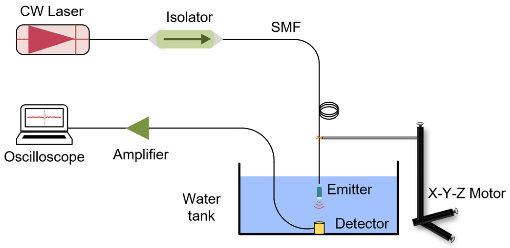
4.1. Test System Setup

We utilized an erbium-doped fiber laser (Bookham LC94, Bookham, San Jose, CA, USA) with a single-mode fiber tail as the light source for generating ultrasonic waves. Prior to detecting the ultrasonic signals, the characteristics of the continuous-wave laser source were measured using an optical spectrum analyzer (YOKOGAWA, AQ6370D, YOKOGAWA, Tokyo, Japan), as shown in Figure 4a. At a room temperature of 20 °C, the central wavelength of the laser used was 974.4 nm. After connecting the entire experimental testing system, we tested the laser output power at the fiber tail using a power meter. A fitting curve illustrating the relationship between laser current versus output power was plotted, as illustrated in Figure 4b.
The experimental setup for testing ultrasonic characteristics is shown in Figure 5. A continuous-wave laser with fiber output serves as the pump laser for the ultrasonic emitter, and the laser power output at the fiber tail can be adjusted by varying the laser current. After the laser passes through a fiber isolator (DH-FOI-980-FA, Daheng Optics, Beijing, China), it reaches the ultrasonic emitter near the fiber end face. The fabricated ultrasonic emitter is immersed in a water tank and secured using an X-Y-Z three-dimensional translation stage with a fixture. In the water tank, a PZT ultrasonic sensor (Olympus, A311S, Olympus, Tokyo, Japan) is aligned with the end face of the ultrasonic emitter to detect the generated ultrasonic signals. The signals received by the ultrasonic sensor are converted into electrical signals, which are then amplified by 26 dB using an amplifier, and finally recorded on a digital oscilloscope (Tektronix MDO32, Tektronix, Beaverton, OR, USA).

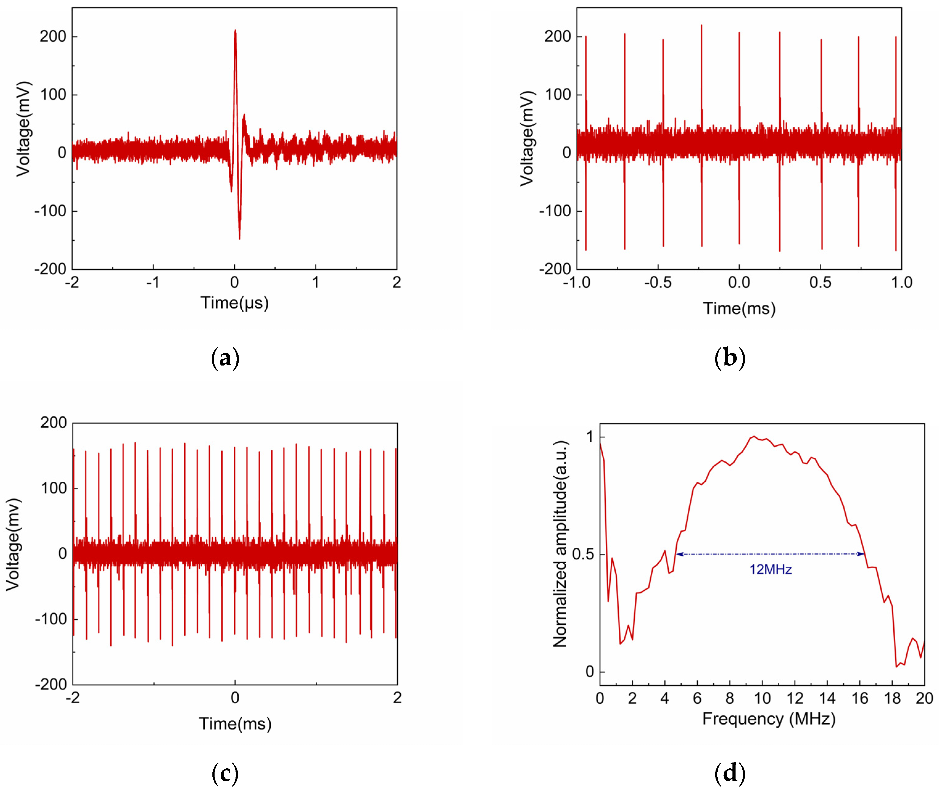
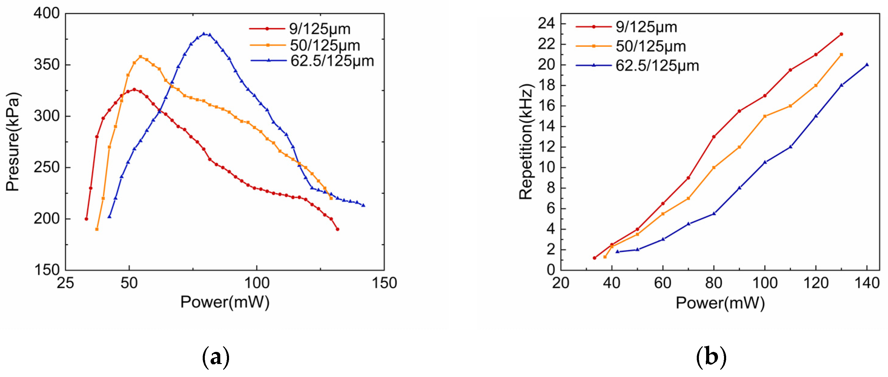
4.2. Results and Analysis

As shown in Figure 6, the ultrasonic characteristics were recorded when copper nitrate solution with 100% saturation was used as the ultrasonic excitation medium. As illustrated in Figure 6a, the amplitude of a single pulse ultrasonic signal was measured to be about 360 mV at 52 mW optical power. Additionally, from Figure 6b,c, we found that the thermal cavitation is not an independent process but exhibits repeatability, with a repetition rate of about 4 kHz at 50 mW optical power and about 13 kHz at 80 mW. The amplitude of each pulse is not entirely identical, and the recorded pulse amplitude exhibits fluctuations during the experiment, with minor differences in the amplitude size of individual pulse signals. We attribute these variations in pulse signals primarily to factors such as the temperature of the cavitation liquid and the power stability of the laser. During the experiment, the continuous-wave (CW) laser remains in the “on” state, but it cannot be guaranteed that the output power of the CW laser is absolutely constant. Figure 6d shows the ultrasonic frequency bandwidth obtained by performing a Fourier transform on a single recorded ultrasonic pulse signal. The frequency bandwidth ranges from 5 to 17 MHz and exhibits a relatively flat spectrum. This ultrasonic emitter’s operating frequency and bandwidth advantages make it highly suitable for high-resolution detection of delicate structures and micro-defects and provide good penetration depth. In medical imaging, high-frequency ultrasound can clearly display superficial vascular structures, and when combined with its bandwidth advantages, it can deliver high-quality dynamic blood flow information [22]. Since cavitation occurs only in a small region near the fiber tip [23] and has a much smaller size than the PTFE tube with an inner diameter of 0.8 mm, subsequent attempts can be made to reduce the size of the PTFE tube to minimize the overall size of the ultrasonic emitter. Moreover, under unchanged experimental conditions, we replaced the tube material of the ultrasonic emitter with a glass tube that has similar acoustic impedance and chemical stability to PTFE. The resulting ultrasonic signal characteristics remained largely unchanged.
Different concentrations of copper nitrate (Cu(NO3)2) solutions were selected to investigate the effect of absorption on ultrasonic performance. In this experiment, solutions containing 13.78 g, 6.89 g, and 3.45 g of copper nitrate per 10 mL of water at room temperature were prepared, the saturation of copper nitrate was 100%, 50%, and 25%, respectively. Figure 7 shows the amplitude and repetition rate of ultrasonic pulses generated by copper nitrate solutions with different saturation levels under varying heating powers. It is evident that higher-concentration solutions require lower threshold power to excite ultrasound. The threshold power for excitation of ultrasound in saturated solution is 33 MW, whereas the corresponding threshold power for solutions with saturation of 50% and 25% is 69 MW and 114 MW, respectively. This is because increasing the solution concentration enhances the absorption coefficient, leading to greater local energy absorption and faster heating of the liquid to the thermal limit temperature, thereby generating cavitation bubbles. The absorption coefficient of the saturated Cu(NO3)2 solution (α = 135 cm−1) is significant at wavelengths around 974 nm such that the light is strongly absorbed near the fiber end face [24]. By increasing the solution concentration, the required laser energy will also be reduced, making the use of the laser more economical.
Additionally, it can be observed that the ultrasonic pressure increases with increasing heating power at low laser power, but continuously increasing the laser power does not indefinitely enhance the ultrasonic pressure. At low power, the heat at the fiber end face is limited, and the diffusion range is small, resulting in small bubble diameters when cavitation conditions are met, which leads to weaker ultrasonic signals. With the increase in power to promote heat diffusion to a larger volume of liquid, the time to produce cavitation becomes longer, the volume of the cavitation bubble increases, and the ultrasonic signal emitted subsequently becomes stronger [18]. In the saturated solution, the maximum ultrasonic pressure achieved at 52 mw optical power is 326 kPa. However, since there is a threshold for liquid heating in thermal cavitation, excessive heating power cannot further expand the thermal diffusion range, so the bubble diameter cannot be increased all the time, and the ultrasonic signal does not become more vigorous. Increasing the power accelerates the cavitation process, shortening the duration of cavitation and increasing the repetition frequency, as shown in Figure 7b. The repetition frequency increases, and the volume of superheated liquid is smaller than that at low power, which means that the energy accumulation time becomes shorter, reducing the diameter of the bubbles and affecting the ultrasonic pressure intensity.
Figure 8 illustrates the ultrasonic characteristics generated using fibers with different core diameters. In the experiment, fibers with core diameters of 9/125 μm, 50/125 μm, and 62.5/125 μm were used, and they were connected to the optical path via flanges for testing. The results show that the relationship between heating power and amplitude with different core diameters of fibers behaves similarly to that in solutions of different concentrations, and the correlation between the heating power and repetition rate is also relatively good. In the case of saturated copper salt solution concentration, the thresholds of the three core diameters of the fibers to generate ultrasound are 33 mw, 37 mw, and 42 mw, respectively, and the thresholds are positively correlated with their core diameter sizes, indicating that larger core sizes require more considerable optical energy to generate ultrasound. This is because the more prominent fiber core diameter end face produces a larger laser irradiation area, which will heat a larger volume of liquid before the bubbles nucleate, requiring more optical energy to reach the threshold temperature for cavitation. As can be seen in Figure 8a, the maximum acoustic pressure that can be generated by the fiber with a core diameter size of 62.5/125 μm with a heating power of 79 MW is 380 kPa, and the acoustic pressure generated by the 50/125 μm fiber with a heating power of 56.9 MW is 360 kPa, which is a significant enhancement in the amplitude of the ultrasonic signals compared to that of the smallest size of the single-mode fiber. This is because when the volume of the heated liquid increases, more laser power will be required to form larger cavitation bubbles and accumulate more energy, so the more significant the core diameter of the fiber, the greater the energy released when the resulting cavitation bubbles collapse, and the greater the amplitude of the resulting ultrasound. From Figure 8b, it can be seen that under the same laser power, the ultrasonic repetition rate generated by the larger core diameter size of the fiber is lower. With the increase of laser heating power, the ultrasonic repetition rate generated by the different core diameter sizes of the fiber varies significantly. It becomes more significant with the increase of the laser power, which is similar to the effect of the concentration of the solution on the repetition rate. The increase of the power will lead to the speed of the cavitation, which will make the process of the cavitation time shorter; the shorter the time required for cavitation, the higher the repetition frequency of ultrasound. In short, the size of the core represents the size of the heating point source, and the size of the focusing spot affects the superheated area near the fiber end face; the more significant the focusing spot, the larger the diameter of the resulting cavitation bubbles, so that the bubble collapse is instantaneous and ultrasonic pressure is issued by the stronger, the longer the time required for cavitation, the ultrasonic repetition frequency is also lower. This phenomenon further verifies the significant effect of fiber core diameter on the intensity of ultrasound generation.

5. Conclusions

In this study, a fiber-optic ultrasonic emitter based on the thermal cavitation effect was successfully prepared, and its performance was investigated. The emitter utilizes a low-power continuous-wave laser transmitted through an optical fiber to excite ultrasound. The experimental results show that the laser power, the concentration of the solution inducing thermal cavitation, and the fiber core diameter have significant effects on the ultrasonic characteristics. When using a saturated copper salt solution as the ultrasonic excitation medium, we achieved ultrasound pulses with an amplitude of 330 kPa and a repetition rate of 4 kHz in the frequency range of 5–17 MHz, and a bandwidth of 12 MHz was obtained by using a low laser heating power of 52 mW at a wavelength of 974 nm. This ultrasonic emission method avoids the use of optical components, such as lenses, to guide and focus the laser in free space, greatly simplifying the ultrasonic emission system. The fiber optic ultrasound emitter is simple to prepare, small, flexible, and safer to use at a lower cost compared to pulsed laser sonication.
However, the heavy metal salt solution in the ultrasonic emitter is toxic to human beings and must be strictly sealed during the preparation process. Although no leakage was found during the experiments, the encapsulation materials and methods need further improvement to minimize the risk of leakage and increase the service life. In addition, the ultrasonic characteristics may also be affected by the flatness and smoothness of the fiber end face, and the influence of this factor needs to be further explored. In the future, encapsulation parameters such as tubing, wall thickness, and inner diameter dimensions will be optimized to reduce emitter size and ultrasonic transmission loss further. The following are a few engaging scenarios to try to explore: using other kinds of solutions to improve the absorption of light by the solution, which is beneficial to reduce further the threshold optical power for excitation of thermal cavitation; one can try to open up the ultrasonic transmission window on the side of the tube wall to meet the application requirements in different scenarios; switching to different kinds of optical fibers such as gradual-refractive-index (GRIN) fibers, to change the laser outgoing on the end face of the optical fiber The spot size of the laser beam at the end face of the fiber can be changed further to increase the sound pressure of the emitted ultrasound. In conclusion, this high-frequency, wide-bandwidth, and compact fiber-optic ultrasonic emitter is poised to play a significant role in the future across various fields, including medicine, industry, biological research, and materials science. It promises to deliver high-resolution imaging and precise detection capabilities, while also being easily integrated into small medical devices, making it suitable for applications in confined spaces, such as nondestructive testing. This study offers new ideas and methods for developing high-performance, cost-effective ultrasonic emitters with considerable application potential.

Author Contributions

Conceptualization, W.K. and Y.Q.; methodology, Q.Z. and J.S.; investigation, D.X. (Dongxin Xu); data curation, M.W. and D.X. (Dongliang Xie); supervision, Y.Q. and Q.Z.; project administration, Y.Q. and Q.Z.; writing—original draft preparation, W.K.; writing—review and editing, J.S. funding acquisition, Y.Q. All authors have read and agreed to the published version of the manuscript.

Funding

This research was funded by the Hainan Province Science and Technology Special Fund (ZDYF2025GXJS007) and the National Natural Science Foundation of China (62464006).

Institutional Review Board Statement

Not applicable.

Informed Consent Statement

Informed consent was obtained from all subjects involved in the study.

Data Availability Statement

The original contributions presented in this study are included in this article. Further inquiries can be directed to the corresponding author.

Conflicts of Interest

Jianqiang Sheng was employed by the Everdisplay Optronics (Shanghai) Co., Ltd. The remaining authors declare that the research was conducted in the absence of any commercial or financial relationships that could be construed as a potential conflict of interest.

References

  1. Colchester, R.J.; Zhang, E.Z.; Mosse, C.A.; Breard, P.C.; Papakonstantinou, I.; Desjardins, A.E. Broadband miniature optical ultrasound probe for high resolution vascular tissue imaging. Biomed. Opt. Express 2015, 6, 1502–1511. [Google Scholar] [CrossRef] [PubMed]
  2. Huang, C.C.; Chen, P.Y.; Peng, P.H.; Lee, P.Y. 40 MHz high-frequency ultrafast ultrasound imaging. Med. Phys. 2017, 44, 2185–2195. [Google Scholar] [CrossRef] [PubMed]
  3. Wu, Q.; Wang, R.; Yu, F.M.; Okabe, Y. Application of an optical fiber ultrasonic sensor for nonlinear evaluation of fatigue crack. IEEE Sens. J. 2019, 19, 4992–4999. [Google Scholar] [CrossRef]
  4. Lee, W.; Roh, Y. Ultrasonic transducers for medical diagnostic imaging. Biomed. Eng. Lett. 2017, 7, 91–97. [Google Scholar] [CrossRef] [PubMed]
  5. Li, Q.; Li, J.P.; Zhu, H.B.; Chen, Y.J.; Zhu, B.P. Dynamic acoustic focusing in photoacoustic transmitter. Photoacoustics 2021, 21, 100224. [Google Scholar] [CrossRef] [PubMed]
  6. Xie, L.Y.; Lian, Y.D.; Du, F.J.; Wang, Y.L.; Lu, Z.W. Optical methods of laser ultrasonic testing technology in the industrial and engineering applications: A review. Opt. Laser Technol. 2024, 176, 110876. [Google Scholar] [CrossRef]
  7. Li, J.P.; Xu, J.B.; Liu, X.L.; Zhang, T.; Lei, S.; Jiang, L.M.; Yang, J.O.; Yang, X.F.; Zhu, B.P. A novel CNTs array PDMS composite with anisotropic thermal conductivity for optoacoustic transducer applications. Compos. Part B 2020, 196, 108073. [Google Scholar] [CrossRef]
  8. Zou, X.T.; Wu, N.; Tian, Y.; Wang, X.W. Broadband miniature fiber optic ultrasound generator. Opt. Express 2014, 22, 18119–18127. [Google Scholar] [CrossRef] [PubMed]
  9. La Cavera, S.; Pérez-Cota, F.; Smith, R.J.; Clark, M. Phonon imaging in 3D with a fibre probe. Light. Sci. Appl. 2021, 10, 91. [Google Scholar] [CrossRef] [PubMed]
  10. Song, W.T.; Hong, M.H.; Lukyanchuk, B.; Chong, T.C. Laser-induced cavitation bubbles for cleaning of solid surfaces. Appl. Phys. 2004, 95, 2952–2956. [Google Scholar] [CrossRef]
  11. Vogel, A.; Lauterborn, W. Acoustic transient generation by laser-produced cavitation bubbles near solid boundaries. J. Acoust. Soc. Am. 1988, 84, 719–731. [Google Scholar] [CrossRef]
  12. Ramirez-San-Juan, J.C.; Rodriguez-Aboytes, E.; Koreev, N.; Baldovinos-Pantaleon, O.; Chiu-Zarate, R.; Gutierrez-Juarez, G.; Dominguez-Cruz, R.; Ramos-Garcia, R. Cavitation induced by continuous wave lasers. NanoSci. Eng. 2007, 6644, 301–305. [Google Scholar]
  13. Padilla-Martínez, J.P.; Aguilar, G.; Ramírez-San-Juan, J.C.; Ramos-García, R. Temporal evolution of thermocavitation bubbles using high speed video camera. In Proceedings of the Optical Trapping & Optical Micromanipulation VIII International Society for Optics and Photonics, San Diego, CA, USA, 21–25 August 2011; Volume 8097, p. 809727. [Google Scholar]
  14. Zhang, B.; Banks, D.; Robles, V.; Cruz, L.F.D.; Aguilar, G. High resolution optical investigation of laser intensity and solution temperature effects on thermocavitation. Exp. Therm. Fluid Sci. 2022, 136, 110683. [Google Scholar] [CrossRef]
  15. Yusupov, V.I.; Konovalov, A.N.; Ul’yanov, V.A.; Bagratashvili, V.N. Generation of acoustic waves by cw laser radiation at the tip of an optical fiber in water. Acoust. Phys. 2016, 62, 537–544. [Google Scholar] [CrossRef]
  16. Schoppink, J.J.; Krizek, J.; Moser, C.; Rivas, D.F. Cavitation induced by pulsed and continuous-wave fiber lasers in confinement. Exp. Therm. Fluid Sci. 2023, 146, 110926. [Google Scholar] [CrossRef]
  17. Jackson, J.D. Classical Electrodynamics, 3rd ed.; Wiley: Hoboken, NJ, USA, 1998; pp. 35–38. [Google Scholar]
  18. Zaca-Morán, R.; Amaxal-Cuatetl, C.; Zaca-Moran, P.; Castillo-Mixcóatl, J.; Ramos-Garcia, R.; Padilla-Martinez, J.P. Thermocavitation: A mechanism to pulse fiber lasers. Opt. Express. 2021, 29, 23439–23446. [Google Scholar] [CrossRef] [PubMed]
  19. Krizek, J.; De Goumoëns, F.; Delrot, P.; Moser, C. Needle-free delivery of fluids from compact laser-based jet injector. Lab Chip 2020, 20, 3784–3791. [Google Scholar] [CrossRef] [PubMed]
  20. Korneev, N.; Montero, P.R.; Ramos-Garcia, R.; Ramirez-San-Juan, J.C.; Padilla-Martinez, J.P. Ultrasound induced by CW laser cavitation bubbles. In Proceedings of the 2nd International Symposium on Laser-Ultrasonics-Science, Technology and Applications, Talence, France, 5–8 July 2010. [Google Scholar]
  21. Vogel, A.; Venugopalan, V. Mechanisms of pulsed laser ablation of biological tissues. Chem. Rev. 2003, 103, 577–644. [Google Scholar] [CrossRef] [PubMed]
  22. Heng, J.; Li, C.; Chu, T.; Xu, Y.; Jian, X. A Method for High-Frequency Mechanical Scanning Ultrasonic Flow Imaging with Motion Compensation. Diagnostics 2023, 13, 1467. [Google Scholar] [CrossRef] [PubMed]
  23. Liu, H.J.; Wu, Y.; Hou, C.; Chen, Z.; Shen, B.; Luo, Z.; Liang, H.; Ma, J.; Guan, B.O. Ultrasound pulse generation through continuous-wave laser excited thermo-cavitation for all-optical ultrasound imaging. Appl. Photonics 2023, 8, 046102. [Google Scholar] [CrossRef]
  24. Ramirez-San-Juan, J.C.; Rodriguez-Aboytes, E.; Martinez-Canton, A.E.; Baldovino-Pantaleon, O.; Robledo-Martinez, A.; Korneev, N.; Ramos-Garcia, R. Time-resolved analysis of cavitation induced by CW lasers in absorbing liquids. Opt. Express 2012, 18, 8735–8742. [Google Scholar] [CrossRef] [PubMed]
Figure 1. Principle of the ultrasound generation based on the thermo-cavitation effect.
Coatings 15 00391 g001
Figure 2. The design of the ultrasonic emitter device.
Coatings 15 00391 g002
Figure 3. Physical image of the laboratory-prepared ultrasonic emitter.
Coatings 15 00391 g003
Figure 4. (a) Output spectrum of the laser, and the red dotted line indicates that the center wavelength of the laser is 974.4nm; (b) Fitting curve of laser current versus output power.
Coatings 15 00391 g004
Figure 5. Ultrasonic characteristic testing experimental system diagram.
Coatings 15 00391 g005
Figure 6. The signal measured when using a saturated Cu(NO3)2 solution and a single-mode optical fiber: (a) Amplitude of a single ultrasonic signal measured at an optical power of 50 mW; (b) Repetition frequency of the ultrasonic signal measured at an optical power of 50 mW; (c) Repetition frequency of the ultrasonic signal measured at an optical power of 80 mW. (d) Ultrasonic frequency band obtained by performing a Fourier transform on a single ultrasonic pulse signal.
Coatings 15 00391 g006
Figure 7. (a) Pulse amplitude and (b) repetition rate under different copper nitrate solution concentrations and heating powers.
Coatings 15 00391 g007
Figure 8. (a) Pulse amplitude and (b) repetition rate under fibers with different core diameters and varying concentrations of copper nitrate solution.
Coatings 15 00391 g008
Disclaimer/Publisher’s Note: The statements, opinions and data contained in all publications are solely those of the individual author(s) and contributor(s) and not of MDPI and/or the editor(s). MDPI and/or the editor(s) disclaim responsibility for any injury to people or property resulting from any ideas, methods, instructions or products referred to in the content.

