Article

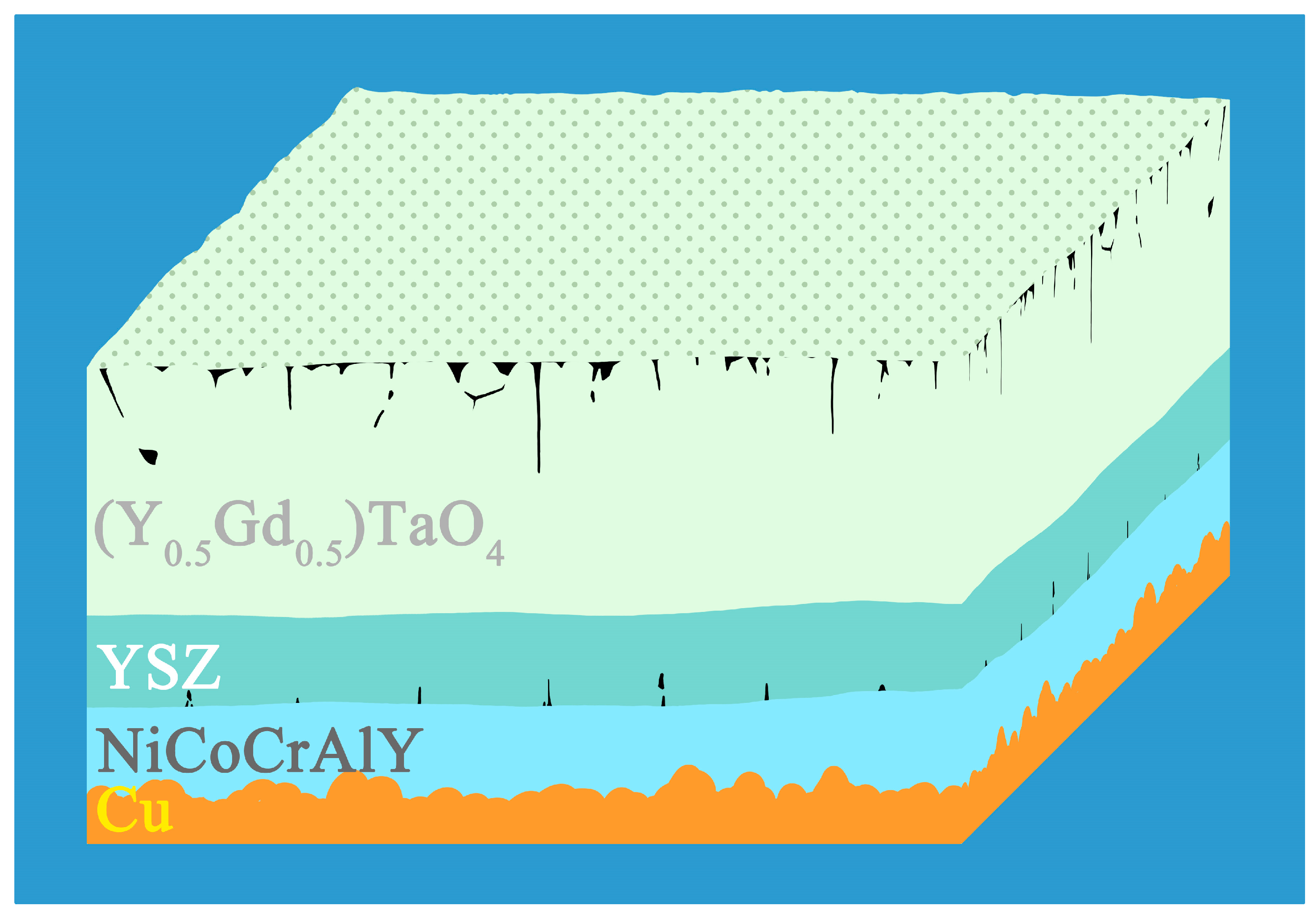
Microstructural Evolution and Failure Analysis for 8YSZ/(Y0.5Gd0.5)TaO4 Double-Ceramic-Layer Thermal Barrier Coatings on Copper Substrate

Faculty of Materials Science and Engineering, Kunming University of Science and Technology, Kunming 650093, China
*
Authors to whom correspondence should be addressed.
Coatings 2025, 15(4), 451; https://doi.org/10.3390/coatings15040451
Submission received: 3 March 2025 / Revised: 27 March 2025 / Accepted: 7 April 2025 / Published: 11 April 2025

Abstract

:
The main purpose of this work is to suppress the rate of thermal and oxidative corrosion of copper substrates using double-ceramic-layer thermal barrier coatings (TBCs). Herein, the orthogonal spray experiment was employed to optimize the spraying parameters for TBCs consisting of Cu/NiCoCrAlY/8YSZ/(Y0.5Gd0.5)TaO4. The thermal cycling and average mass loss rate of TBCs prepared by atmospheric plasma spraying (APS) with optimum spraying parameters correspond to 20 cycles and 0.56‰, respectively. The thermal conductivity (0.39 W·m−1·K−1 at 900 °C) of (Y0.5Gd0.5)TaO4 is 71.68% and 52.7% lower than that of (Y0.5Gd0.5)TaO4 bulk and 8YSZ, respectively. Meanwhile, the bond strength increased from 8.86 MPa to 14.03 MPa as the heat treatment time increased from 0 h to 24 h, benefiting from the heat treatment to release the residual stresses inside the coating. Additionally, the hardness increased from 5.88 ± 0.56 GPa to 7.9 ± 0.64 GPa as the heat treatment temperature increased from room temperature to 1000 °C, resulting from the healing of pores and increased densification. Lastly, crack growth driven by thermal stress mismatch accumulated during thermal cycling is the main cause of coating failure. The above results demonstrated that 8YSZ/(Y0.5Gd0.5)TaO4 can increase the service span of copper substrate.

1. Introduction

Copper is extensively utilized in the production of various heat-resistant components and heat exchangers in industry owing to its superior casting properties and high thermal conductivity. The blast furnace tuyeres and slag openings used in chemical metallurgy are pure copper sleeves that are cooled by circulating water [1]. However, pure copper has a low melting point (1083 °C), low surface hardness, and poor wear resistance. Moreover, pure copper sleeves are often used in high temperatures (>1200 °C) [2,3]. Hence, it is critical to deal with the fact that copper substrates are resistant to wear and high temperatures.
Protective coatings and circulating water cooling are the current mainstays for extending the useful life of copper-based products exposed to high temperatures. Kumar et al. [4] demonstrate that optimizing tuyere design and coating treatments effectively reduces heat loss in blast furnaces, enhances tuyere durability, and improves operating efficiency. Zhang et al. [5] applied a Ni60A coating on copper, satisfying the wear resistance criteria for the blast furnace tuyere; nevertheless, its resistance to molten metal erosion was inadequate. Pathak et al. [6] applied NiCoCrAlY-YSZ-Al2O3 + ZrO2 onto the tuyere and used APS methods to enhance the efficacy of various coatings. The findings indicated that the YSZ coating exhibited excellent thermal cycling resistance. The service life of the tuyere is increased by a factor of 1.9 in real manufacturing. However, despite the advantages of circulating water cooling, it may lead to uneven cooling, leading to localized thermal stress inside the tuyere structure, hence heightening the risk of fracture development and propagation [7,8]. Furthermore, if the tuyere sustains significant damage, cooling water may infiltrate the blast furnace, potentially resulting in an explosion [9]. Coating protection is a relatively reliable protective technology, but research is still insufficient. There is an urgent need to find new types of coating materials that are resistant to high temperatures, oxidation, corrosion, and wear.
Rare-earth tantalates represent a novel category of thermally protective coating materials, distinguished by their remarkable high-temperature stability, little thermal conductivity, and superior resistance to oxidation and corrosion, hence offering a broad spectrum of possible applications [10,11,12]. Qu et al. [13] prepared bulk ceramics of (Y1−xGdx)TaO4 ceramics using the solid-phase synthesis method, which has a high phase transition temperature (>1500 °C), a high coefficient of thermal expansion, and a low thermal conductivity. APS is a commonly used method for preparing coatings. Appropriate spraying parameters are critical in order to prepare rare-earth tantalate coatings for long-term service at high temperatures via APS. The orthogonal experiments are able to assess the effect of factors on experimental results and determine the optimal parameter combinations through range analyses method. Compared to one- factor experiments and modelling analyses, orthogonal experimental methods have the advantage of being able to increase the efficiency of optimization while reducing the number of experiments and avoiding the need for complex modelling. Li et al. [14] optimized the parameters of AlCoCrFeNi coating in laser cladding, such as laser power, powder feeding rate, and scanning speed, based on the dilution rate by the orthogonal experimental. Zhao et al. [15] used an orthogonal experiment to study the effect of spraying parameters on the microstructure and corrosion resistance of Ti coatings on steel substrates, and the results showed that the spraying parameters have a significant effect on the corrosion resistance.
In this study, the service life of 8YSZ/(Y0.5Gd0.5)TaO4 double-ceramic-layer thermal barrier coatings was improved by optimizing the spraying parameters and appropriate heat treatment. The spraying parameters for the (Y0.5Gd0.5)TaO4 coating were optimized using an orthogonal experiment, such as the current, argon flow rate, hydrogen flow rate, and spraying distance. On the premise of meeting the indicator of low mass loss rate during thermal cycling, the failure mechanism and thermal properties of the coating were studied. Additionally, this study experimentally investigated the effect of heat treatment on coating properties such as microstructure, hardness and bond strength.

2. Experimental Details

2.1. Material Preparation

Copper substrates (purity 99.99%) with dimensions of 18 mm × 15 mm × 3 mm and cylindrical substrates (φ25 mm × 4 mm), together with cylindrical graphite substrates (φ25 mm × 4 mm), are utilized as substrate materials. The (Y0.5Gd0.5)TaO4 coating was applied to the graphite to investigate the thermal performance of the coating and the development of high-temperature phase structures. The (Y0.5Gd0.5)TaO4 coating on the graphite substrate was subjected to a tube furnace at 1400 °C for 12 h to eliminate the graphite. Graphite is susceptible to oxidation and volatilization; hence, the impact of graphite components on the coating’s thermal performance and phase structure is minor. Prior to spraying, the pure copper substrate underwent pretreatment, which involved sandblasting with 1 mm-diameter corundum to expose fresh metal and preserve a certain roughness.
On the copper surface, the bonding coating (BC) and the YSZ/(Y0.5Gd0.5)TaO4 double-ceramic-layer thermal barrier coatings were successively prepared by atmospheric plasma spray torch (SH-PQ-48K, XiaMen Sheng Hua Automation equipment Co.,Lte, Xiamen, China), as shown in Figure 1. The BC used NiCoCrAlY alloy powder produced by Jinzhou City Jinjiang Spraying Material Co., Ltd. (Jinzhou, China) with a particle size of 30 to 80 μm. Table 1 shows the composition of the NiCoCrAlY alloy powder. The ceramic coating used 8YSZ (8 wt.% Y2O3 stabilized Z2O3) ceramic powder with a size of 30–80 μm (Oerlikon Metco 204NS-G, Oerlikon Metco Surface Technology Co., Ltd., Shanghai, China) and (Y0.5Gd0.5)TaO4 ceramic powder with a particle size of 45–100 μm (Shanxi Tianxuan Coating Technology Co., Ltd., Xi’an, China); Figure 2a shows an SEM image of the (Y0.5Gd0.5)TaO4 ceramic powder with an average particle size of 58.79 μm, and Figure 2b shows the particle size distribution in the (Y0.5Gd0.5)TaO4 with the D50 = 59.32 μm measured by the laser particle sizer, both data are comparable. Table 2 demonstrates the spraying parameters for BC and 8YSZ coating, and Table 3 shows the orthogonal experiment factor level table. Table 4 shows spraying parameters for (Y0.5Gd0.5)TaO4#1–9 coatings, and Figure 5e shows the optimal spraying parameters of the (Y0.5Gd0.5)TaO4#10 coating.

2.2. Characterization

The phase was analyzed using X-ray diffraction (XRD, MiniFlex600, Rigaku, Akishima, Japan) at a scanning rate of 5°/min within the 20–65° range, identifying the phases of the (Y0.5Gd0.5)TaO4 coating with reference to the standard ICDD PDF cards in the system.
The actual density of the upper ceramic was measured ten times using a coating thickness gauge (THS-12, Shenzhen ThreeNH Technology Co., Ltd., Shanghai, China). The bulk density, ρ, was determined using the Archimedes technique. Thermal diffusivity (α) was measured using the laser flash analyzer (NETZSCH LFA 457, Netzsch, Selb, Germany) throughout a temperature range from ambient temperature to 900 °C. All samples must be coated with a thin coating of colloidal graphite and gold on both sides prior to measurement. The thermal conductivity (κ) is determined using the usual relationship:
κ = α ρ C p
where heat capacity Cp is obtained from DSC (STA-449-F3, Netzsch, Selby, Germany) experiments.
The thermal expansion rate (dL/dL0) and thermal expansion coefficients (TECs) of the (Y0.5Gd0.5)TaO4 coating were measured by the thermo-mechanical analyzer (NETZSCH TMA 402 F3, Germany) from room temperature to 900 °C. The principle is that the thermal expansion rate (dL/dL0) during temperature change is monitored by a precision displacement sensor, and the TECs at different temperatures are calculated according to the expansion amount at different temperatures, expressed as:
T E C s ( T 1 , T r e f ) = d L L 0 ( T 1 ) d L L 0 ( T r e f ) T 1 T r e f
where T1 is the test temperature and Tref is the reference temperature; the reference temperature is generally set to room temperature.
The Vickers hardness of the (Y0.5Gd0.5)TaO4 coating after different heat treatment temperatures was assessed utilizing Shimadzu HMV-G Automatic Micro Vickers Hardness Tester (Laizhou Hengyi Test Instrument Co., Ltd., Laizhou, China). Each specimen underwent a 1000 N load for ten seconds at six equidistant sites (2 mm apart) to guarantee a thorough evaluation of the coating’s hardness. Before testing, the sample surfaces were carefully polished using diamond abrasives to obtain a consistent surface quality. The Vickers hardness (Hv) was determined utilizing the formula:
H v = 1.854 F d 2
where F is the indentation load and d is the indent diagonal. The bond strength of the coating system was evaluated using a pull-off test (MTS E45.305, Ningbo Weiheng Testing Instrument Co., Ltd., Ningbo, China) in accordance with ISO 4624:2002 [16], employing a strain rate of 5 mm/min. The glue utilized in the experiment was epoxy adhesive (FM1000), manufactured by Foshan Advanced Surface Technology Co., Ltd. (Foshan, China). The assembly of the pull rod, adhesive, and (Y0.5Gd0.5)TaO4 coating depicted in Figure 9a was subjected to curing at 185 °C for 2 h. The sample was measured three times to minimize experimental uncertainty, and average results were computed.
The heat treatment was carried out in a tube furnace (SK-G08143-3-600, TIANJIN ZHONGHUAN FURNACE Corp., Tianjin, China) in order to investigate the effect of different heat treatment conditions on the (Y0.5Gd0.5)TaO4 coating. The coating was heated at different temperatures at a rate of 5 °C/min and then allowed to cool naturally to room temperature.
The thermal cycling test for the (Y0.5Gd0.5)TaO4 coating were conducted in a high-temperature tubular furnace (OTF-1200X-S, Kejin Hefei Corp., Hefei, China). Thermal cycling was performed at a temperature of 600 °C, held for 10 min, and then cooled to room temperature in air. The coating was deemed invalid if the area of coating detachment exceeded approximately 10%.

3. Results and Discussion

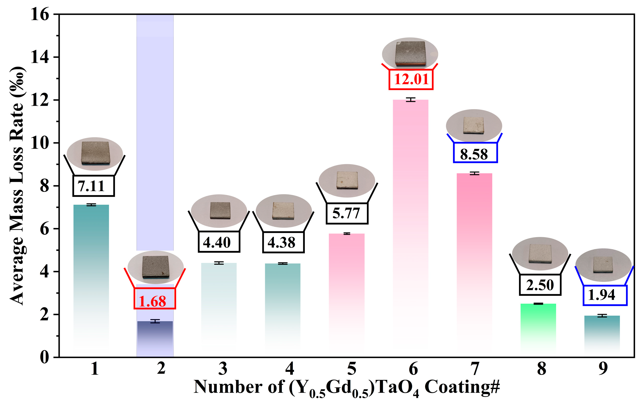
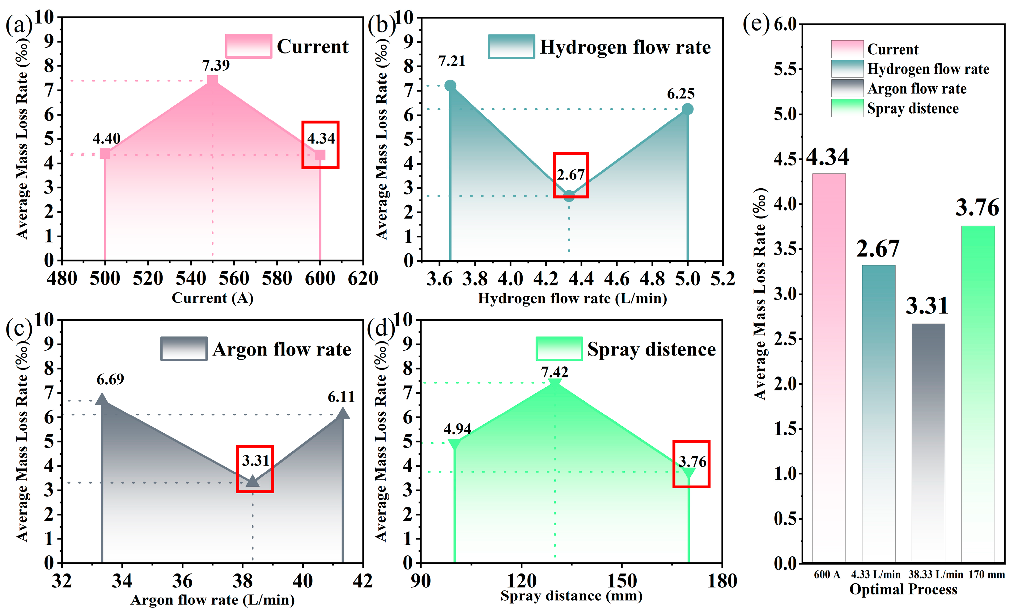
3.1. Orthogonal Spray Experiment

Figure 3a–i show the backscattered electron images (BSEs) of double-ceramic-layer 8YSZ/(Y0.5Gd0.5)TaO4 coatings with a typical layered structure. The reason for preparing a double-ceramic-layer structure is that the TECs of 8YSZ is between BC and (Y0.5Gd0.5)TaO4, which has better thermal matching properties and superior thermal cycling resistance than the single ceramic layer [17,18,19]. In the nine samples, the thicknesses of the BC and 8YSZ coating correspond to 100 to 150 μm and 150 to 200 μm, respectively. However, the thickness of the (Y0.5Gd0.5)TaO4 coating has a large range of variation (150 to 400 μm), as different spraying parameters lead to various deposition rates and coating thicknesses. First, a short spray distance reduces heat loss and increases the powder melting rate, resulting in higher coating deposition rates and thicker coatings, and vice versa [20,21]. Second, higher flow rates lead to better melting and thicker coatings [22]. Last, increasing the voltage and current allows larger spraying power, which boosts the coating thickness and powder melt rate; instead, the high spraying power may lead to the vaporization of the powder or damage to the metal substrate due to high temperatures [23].
Figure 3b,c,g show horizontal cracks in the (Y0.5Gd0.5)TaO4#2–3 and #7 coatings, which are attributed to thermal stress mismatch between the ceramic and the substrate [24]. The vertical cracks in the (Y0.5Gd0.5)TaO4#1–4, and #6–7 coatings in Figure 3a–d,f,g are caused by the quenching stress generated during the cooling of molten or semi-molten particles [25]. Both vertical and horizontal cracks appear in the (Y0.5Gd0.5)TaO4#2 and #7 coatings in Figure 3b,g, which are induced by thermal stresses due to the high hydrogen flow rate (#2 at 4.33 L/min and #7 at 5 L/min) at a spray distance of 130 mm. Additionally, micropores observed in the (Y0.5Gd0.5)TaO4#8–9 coatings in Figure 3h,i significantly impact the coating’s density, bond strength, and thermal cycling resistance [26]. Plasma spraying inevitably produces microscopic defects in the coating. First, a shorter spray distance can lead to excessive particle melting and cracking, while a longer spray distance tends to increase porosity due to rapid cooling of the particles. Furthermore, a high flow rate reduces porosity, while excessive flow may induce thermal stresses [27]. Lastly, high spray power increases plasma temperature and particle melting, thereby enhancing coating density. However, excessive values can result in overheating, cracking, or surface roughness.
Figure 3j shows the XRD patterns of the (Y0.5Gd0.5)TaO4 powder with the M′ phase (metastable monoclinic phase, PDF 97-023-8536) at room temperature, and the as-sprayed (Y0.5Gd0.5)TaO4#1–9 coatings exhibit the T′ phase (metastable tetragonal phase, PDF 97-015-7741), indicating that the powder undergoes a phase transformation from the low-temperature M′ phase to the high-temperature T′ phase during the spraying process, and these results are similar to the phase transition of YTaO4 [28].
Orthogonal spray experiments were performed to obtain the (Y0.5Gd0.5)TaO4 coating with high thermal cycling performance. The average mass loss rate of the coating for thermal cycling tests, as an indicator for evaluating coating properties, can effectively show the effect of spraying parameters on the service life of the coating. Figure 4 shows the macroscopic morphology of the coatings with different spraying parameters and their matching average mass loss rates after 20 cycles of thermal cycling at 600 °C, where 600 °C is the real temperature of Cu in service. The surface color of the coating is grey or grey-white; the results originated from the PVA in the spherical powder that does not burn and evaporate in time when the spray distance or the spraying power is small, resulting in a grey coating. On the contrary, when the spray distance is large, the PVA evaporates sufficiently, and the coating is intrinsically grey-white. Meanwhile, (Y0.5Gd0.5)TaO4#6 coating and (Y0.5Gd0.5)TaO4#2 coating correspond to the highest and lowest average mass loss rates among these nine samples, respectively, indicating that the variation in parameters influences the average mass loss rate. At a spray distance of 130 mm, despite the (Y0.5Gd0.5)TaO4#6 coating having higher argon flow (41.33 L/min) and current (550 A), the lower hydrogen gas flow (3.66 L/min) and the occurrence of coating delamination suggest that the bond strength between the coating and the substrate may be insufficient, which ultimately results in lower performance compared to the (Y0.5Gd0.5)TaO4#2 coating (argon flow at 38.33 L/min, current at 500 A, and hydrogen gas flow at 4.33 L/min). Additionally, a lower hydrogen flow rate can contribute to coating delamination by reducing the plasma flame temperature. This decrease in temperature may result in insufficient powder melting, ultimately leading to lower coating adhesion.
The optimal spraying parameters for the (Y0.5Gd0.5)TaO4 coating were selected based on the average mass loss rate for three samples after 20 thermal cycles. The results of the orthogonal spray experiments were analyzed using the range analysis method, where the Ki value, which is the sum of the average mass loss rates at all levels for each spraying parameter, was used to quantify the overall effect of the spraying parameters on thermal cycling resistance. A larger Ki value indicates a stronger effect of the corresponding parameter on the thermal cycling resistance. The ki value represents the average mass loss rate at a specific parameter level, with a smaller ki value indicating better thermal cycling resistance. The rang (R) value reflects the extent to which the spraying parameters influence thermal cycling resistance. Furthermore, the Ki and ki values are calculated using Equation (4) [29], and the R value is calculated using Equation (5) [29].
k i = 1 N i K i = 1 N i i = 1 N i Y i
R = max ( K 1 , K 2 , K 3 ) min ( K 1 , K 2 , K 3 )
where i is the number of levels for each spraying parameter, and Yi is the response value of spraying parameters at level ith, Ni represents the number of levels at each spraying parameter.
Range analysis data on the effects of the average mass loss rate are listed Table 5. According to the R data in Table 5, the sequence of R is R (hydrogen flow rate) > R (spray distance) > R (argon flow rate) > R (current). Therefore, hydrogen flow rate is the primary influencing factor of the average mass loss rate, followed by the spray distance and argon flow rate. The optimum parameters with a current of 600 A, an argon flow rate of 38.33 L/min, a hydrogen flow rate of 4.33 L/min, and a spray distance of 170 mm are drawn in Figure 5e. The (Y0.5Gd0.5)TaO4#10 coating has the lowest average mass loss rate 0.56‰ after 20 thermal cycles at 600 °C.
Based on the above, hydrogen flow rate is the main factor affecting the mass loss rate of the (Y0.5Gd0.5)TaO4 coating. The minimum ki value of the average mass loss rate of spraying parameters based on thermal cycling performance at 600 °C is shown in Figure 5a–d. First, Figure 5a shows that the coatings corresponding to currents of 500 A and 600 A have lower mass loss rates, while the coating corresponding to a current of 550 A has a higher mass loss rate. The reason can be attributed to the low powder melting rate at a coating corresponding to a current of 500 A, which results in more coating defects but less thermal stress. When the coating corresponds to a current of 550 A, the powder melting rate increases and there are fewer defects, but the thermal stress increases, resulting in the highest mass loss rate; when the coating current is 600 A, the powder melts completely, resulting in fewer defects and the lowest mass loss rate. Second, Figure 5b shows that the coating corresponding to a hydrogen flow rate of 4.33 L/min has a lower mass loss rate, while the coating corresponding to hydrogen flow rates of 3.66 L/min and 5 L/min has a higher mass loss rate. The reason for this can be attributed to the coating corresponding to a hydrogen flow rate of 3.66 L/min, which results in a lower plasma temperature and a low particle flight speed. The powder melted to a lesser extent, which caused the powder to solidify prematurely and resulted in a large number of defects such as vertical cracks. When the hydrogen flow rate corresponding to the coating was 4.33 L/min, the powder was able to melt sufficiently and quickly deposit on the substrate, and the coating had few defects. When the hydrogen flow rate corresponding to the coating was 5 L/min, the coating had a large amount of thermal stress, which resulted in defects such as horizontal cracks. Third, Figure 5c shows that the coating corresponding to an argon flow rate of 38.33 L/min has a lower mass loss rate, while the coatings corresponding to argon flow rates of 33.33 L/min and 41.33 L/min have a higher mass loss rate. The hydrogen flow rate mainly affects the stability of the plasma and the speed of the particles. Coating corresponds to an argon flow rate of 33.33 L/min; the plasma cannot completely melt the powder. Coating corresponds to an argon flow rate of 41.33 L/min; the plasma causes thermal stress in the coating. When the coating corresponds to an argon flow rate of 38.33 L/min, the powder can be fully melted and defects can be reduced. Last, Figure 5d shows that the coatings corresponding to the spray distances of 100 mm and 170 mm have a lower mass loss rate, while the coating corresponding to the spray distance of 130 mm has a higher mass loss rate. The reason for this can be attributed to the fact that when the coating corresponds to the spray distance of 100 mm, the powder reaches the substrate in a short distance, the powder stays in the flame for a short time, and the coating is composed of completely melted particles with a lot of thermal stress. When the coating corresponds to the spray distance of 130 mm, the prolonged residence time of the powder in the flame results in a mixture of semi-melted and fully melted particles. Consequently, coating defects increase significantly. When the coating corresponds to the spray distance of 170 mm, the flame can fully melt the powder and generate less heat on the substrate.
In addition, Table 6 shows one-way repeated measures and a summary of ANOVA results for spray parameters. The results show that the p value for the hydrogen flow rate is the smallest, which is 0.00399, followed by spray distance, argon flow rate, and current. Therefore, compared with the R value, the hydrogen flow rate is the most important factor affecting the mass loss rate. The p values of hydrogen flow rate and spray distance are all less than 0.050, indicating that they have a significant effect on the mass loss rate. The p value for the argon flow rate is close to 0.05, indicating a possible marginal significance. A p value of currents higher than 0.05 indicates that it does not have a significant effect. The reason can be attributed to the narrow range of current values, which has a limited effect on the mass loss rate.
The average mass loss rate was influenced by porosity and thickness caused via spraying parameters. The (Y0.5Gd0.5)TaO4 coating #10 has an optimum porosity of 6.15% and thickness of 185 μm under optimum spray parameters. Lower porosity (<5%) [29] and larger thickness (>300 μm) [30] result in coatings with large internal stresses, enabling rapid propagation of cracks within the coating and thereby enhancing the mass loss rate. In addition, large porosity leads to structural collapse of the coating at elevated temperatures, resulting in rapid spalling and failure of coating [31]. Similarly, Wang et al. [32] report that the mass loss of La-Mo-Si coating after oxidation for 100 h are 7.51% (45 kW), 4.12% (50 kW), 1.18% (55 kW) and 4.59% (60 kW), respectively, indicating the La-Mo-Si coating with suitable porosity at a power of 55 kW can decrease the mass loss rate than other powers. Last, porosity is affected by the parameters in a similar process to deposition rates and coating defects; higher deposition rates and fewer defects generally lead to lower porosity, and vice versa.

3.2. Microstructure

Figure 6a–d show the BSE of (Y0.5Gd0.5)TaO4#10 coating after heat treatment at different temperatures. The as-sprayed (Y0.5Gd0.5)TaO4#10 coating has a thickness of about 185 μm. The (Y0.5Gd0.5)TaO4#10 coatings after heat treatment at room temperature and 900 °C have obvious large pores, whereas there are only a few micropores in the (Y0.5Gd0.5)TaO4#10 coatings after heat treatment at 800 °C and 1000 °C, implying that heat treatment does not completely eliminate the defects within the coating. Moreover, the porosities of (Y0.5Gd0.5)TaO4#10 coatings show a gradual decrease in order of 6.15%, 3.28%, 2.41%, and 2.16% with an increasing temperature. The results are ascribed to the microscopic pores sintering within the coating at high temperatures; similar results were reported by Sudharshan et al. [33]. Figure 6e shows the XRD pattern of the (Y0.5Gd0.5)TaO4 coating below heat treatment at 900 °C is the T′ phase. When the heat treatment temperature was increased to 1000 °C for 6 h, the characteristic peaks at 28.5° and 30° associated with the M′ phase began to appear, indicating that 1000 °C is near the phase transition temperature point of (Y0.5Gd0.5)TaO4. As the temperature was further increased from 1100 °C to 1400 °C, the M′ peak became stronger and the T′ phase weaker. Moreover, (Y0.5Gd0.5)TaO4 coating showed a complete M′ phase after heating at 1400 °C for 12 h. This is in agreement with the results reported by Wang et al. [34], that is, the T′-M′ transition temperature of YTaO4 is about 1450 °C, and the phase transition temperature of (Y0.5Gd0.5)TaO4 is between 1450 and 1500 °C [13]. And Shian et al. [11,35,36,37,38,39,40] reported that the T′-M′ phase transition is a ferroelastic phase transition that causes a small volume difference, indicating that (Y0.5Gd0.5)TaO4 coatings will not fail due to volume differences caused by phase transitions at temperatures lower than 1400 °C.

3.3. Thermal Properties

The TEC determines the match between the coating and the substrate during high temperature, which directly affects the adhesion, crack resistance, and service life of the coating. Figure 7a shows the TECs of the (Y0.5Gd0.5)TaO4 coating after heat treatment at 1400 °C for 12 h. The TECs of the (Y0.5Gd0.5)TaO4 coating are lower than that of the dense (Y0.5Gd0.5)TaO4 bulk when the temperature is lower than 740 °C. The result derives from the fact that pores or cracks in the coating counteract the volume expansion caused by the high temperature. Meanwhile, the TECs of the coatings and dense blocks are close to each other when the temperature exceeds 740 °C, and the TECs of the (Y0.5Gd0.5)TaO4 coating reach a maximum value of 9.98 × 10⁻⁶ K−1 at 900 °C. Both the coating and bulk of (Y0.5Gd0.5)TaO4 with similar densities and compositions have comparable TECs. The reason can be attributed to porosity and cracks are compacted under compressive thermal stress at high temperatures. In addition, Figure 7b shows the linear thermal expansion (dL/dL0) of the (Y0.5Gd0.5)TaO4 coating, which indicates that the coating maintains a stable expansion until 900 °C, possesses a stable lattice structure, and does not undergo significant phase changes or microstructural changes [27,41].
Figure 8 shows that thermal diffusivity and thermal conductivity of the (Y0.5Gd0.5)TaO4 coating decrease with increasing temperature. The reason is that as the temperature increases, the thermal vibrations of the lattice atoms intensify, leading to an increase in phonon scattering [42,43,44]. As shown in Figure 8b, the thermal conductivity of the (Y0.5Gd0.5)TaO4 coating is significantly lower than that of the 8YSZ coating, which is lower by 40.1% and 52.7% at low and high temperatures, respectively, compared to that of the (Y0.5Gd0.5)TaO4 blocks, which decreases by 75.6% and 71.68% at low and high temperatures, respectively. The low thermal conductivity effectively hinders heat transfer from the high-temperature region to the substrate, thereby enhancing the thermal insulation performance. The low thermal conductivity of the coating can be explained by the following two factors. First, the large number of pores and cracks in the coating increases the intensity of phonon scattering, which in turn decreases the phonon mean free range and thermal conductivity [45,46,47]. Second, the air filled in the pores and cracks in the coating, and the thermal conductivity of air (0.03 W·m−1·k−1 at 25 °C) is far lower than that of ceramics, which prevents heat transfer and improves the thermal insulation of the coating [48,49]. Based on the above analysis and results, the small number of pores in the coating is beneficial to reduce the thermal conductivity and improve the thermal insulating properties and contribute to counteracting the volume difference in thermal expansion caused by high temperature, eventually reduces the failure of the coating due to stress damage. Excellent thermal properties are key to improving the service life of the coating and protecting the substrate material.

3.4. Mechanical Properties

Bond strength is a key indicator for evaluating the service life of coatings. Figure 9a shows a schematic diagram of the bond strength test using the tensile method. The copper substrate undergoes significant oxidation at temperatures exceeding 500 °C; herein, the bond strength of the (Y0.5Gd0.5)TaO4 coating after heat treatment at 500 °C for different times is evaluated using the puff-off test. Figure 9b–d show the fractured surface of the (Y0.5Gd0.5)TaO4 coatings after heat treatment at 500 °C for 0 h, 12 h, and 24 h, corresponding to the average bond strength of 8.86 MPa, 13.51 MPa, and 14.03 MPa, respectively. Fractures at the substrate–BC interface appear when the 0 h. The 8YSZ-(Y0.5Gd0.5)TaO4 interfaces appear to fracture when the time is 12 h. For the samples with 24 h, mainly failure occurs in the 8YSZ-(Y0.5Gd0.5)TaO4 interfaces. The results show the stress gradient at the substrate-BC is very high and plays a key role in the fracture behavior when the un-heat treatment. With the increased time of heat treatment at 500 °C, the stress gradient turns small in the 8YSZ-(Y0.5Gd0.5)TaO4 interfaces, which is similar to the results reported by Karaoglanli [51]. The results shows that the bond strength of the (Y0.5Gd0.5)TaO4 coating is the greatest when the heat treatment temperature was 500 °C for 24 h.
Hardness is a key indicator of mechanical properties, reflecting the coating’s resistance to abrasion. Figure 10 shows the Vickers hardness results of (Y0.5Gd0.5)TaO4 coatings with increasing heat treatment temperature. The as-sprayed (Y0.5Gd0.5)TaO4 coating has a low hardness due to its high porosity. Compared to the as-sprayed (Y0.5Gd0.5)TaO4 coating, the hardness of the (Y0.5Gd0.5)TaO4 coatings after heat treatment for 6 h at 700 °C, 800 °C, 900 °C, and 1000 °C increased by 3.40%, 11.90%, 14.97%, and 34.35%, respectively. Pores in the coating appear to sinter, and the densities are improved as the heat treatment temperature increases; thus, the results measured by the indentation method are intrinsic hardness for the (Y0.5Gd0.5)TaO4 coating due to the low probability of contact between the indenter and the pores. Paul et al. [52] also reported similar results that pores and cracks in the coating occur and heal during heat treatment, which can improve the hardness. Based on the above, heat treatment at 500 °C can significantly improve the bond strength of the coating without changing the phase. Heat treatment at 1000 °C can significantly improve the hardness, but it will cause phase transformation and oxidation of pure copper. Therefore, heat treatment at 500 °C can significantly improve the bond strength of the coating to improve the service life while having less effect on the microstructure and hardness of the coating.

3.5. Failure Mechanism

Figure 11 shows the BSE of the (Y0.5Gd0.5)TaO4 coating after various numbers of thermal cycles. We primarily observe and analyze the failure mechanism of the ceramic layer. As shown in Figure 11a, a small number of microcracks were observed, and Figure 11b exhibits cracking that appeared at the interface between the BC and the 8YSZ coating as well as at the top of the coating after 70 thermal cycles. The reason can be attributed to the crack growth due to the accumulation of thermal stresses during the thermal cycling [53,54]. Figure 11c–f show the rapid propagation and growth of vertical cracks when thermal cycles range from 110 to 210, while horizontal cracks appeared and gradually propagated. The results originate from the cumulative release of thermal stress during thermal cycling processes, leading to crack propagation and failure of coating. It is noteworthy that Figure 11f is shorter compared to Figure 11d, the reason can be attributed to ceramic detachment during thermal cycling. In addition, the horizontal cracks were observed between the BC and the copper substrate at other locations after 210 thermal cycles due to the inhomogeneity of crack distribution.
Figure 12 shows the EDS images of TBCs before and after thermal cycling. As shown in Figure 12a, Al exhibits a discontinuous α-Al2O3 layer for reasons related to the content of elemental Al (5.64 wt.%) below 8 wt.% [55]. Additionally, the presence of Cr elemental segregation in the as-sprayed BC can be attributed to the fact that the BC consists of β-NiAl, γ-Ni, and σ-(Co, Cr), and the σ-phase has a low level. The diffusion of Ni and Co elements into the substrate indicates that a metallurgical bond between the BC and the copper substrate, which can be attributed to the fact that Cu, Ni, and Co have unlimited solubility at high temperature and form a solid solution. Y content was relatively small (0.51 wt.% at BC), making it difficult to detect, but it plays a key role in enhancing the adhesion of the oxide scale to the BC [56]; O elements are distributed in the region of the BC, indicating that the BC has been oxidized to form thermally grown oxide (TGO) during the plasma spraying process [57]. Furthermore, as shown in Figure 12a,b, when the crack reaches the BC, the Al element forms a continuous α-Al2O3 layer, the reason for which can be attributed to the ability of high concentrations of Cr (18–22 wt.%) to promote the formation of a continuous α-Al2O3 layer in thermal cycling at lower Al concentrations [58]. The BC is filled with Cr elements attributed to the reduction in the volume fraction of the γ-Ni and the increase in the volume fraction of the β-NiAl and σ phases, which aligns with the results reported by Toscano [59]. The Ni element disappears into the substrate, which can be attributed to the oxidation of the substrate, resulting in a decrease in the Ni-Cu solid solution. This is similar to that reported by Li et al. [60]. In contrast, Co is present in the substrate, which can be attributed to the fact that the solid solubility of Co and Cu is still present [61]. Meanwhile, the O element in Figure 12b is distributed in the substrate region, indicating that the substrate undergoes severe oxidation. Based on the above analysis and results, the thermal cycling not only induces crack growth in the coating but also leads to redistribution and oxidation of alloying elements. Particularly, air can enter through cracks and reach the substrate material when the cracks grow to and reach the bond layer, causing the substrate material to fail quickly and making the protection of the coating meaningless.
Figure 13 illustrates a schematic diagram of thermal cycling failure for TBCs. As shown in Figure 13a, the TBCs prepared APS consist of a copper substrate, a bonding layer, and both the 8YSZ and (Y0.5Gd0.5)TaO4 ceramic layers. Pores or microcracks, resulting from incompletely melted particles during the spraying process, can easily become the source of cracks. In addition, the TECs of the substrate Cu (17.5 × 10⁻⁶ K−1 at 900 °C) are significantly higher than that of the ceramic layer (9.98 × 10⁻⁶ K−1 at 900 °C), which leads to thermal stress mismatch between the two during heating, which results in the formation of compressive stresses in the substrate and tensile stresses in the ceramic coating. Conversely, both tensile stresses are formed in the substrate and compressive stresses are formed in the ceramic coating during the cooling process in Figure 13b. As shown in Figure 13c, under the cyclic effect of tensile and compressive stresses, the cracks begin to expand until the coating is filled with cracks both inside and on the surface. Eventually, the ceramic coating peels off and fails, and the BC separates from the substrate and peels off and fails, as shown in Figure 13d when large cracks form inside the coating.

4. Conclusions

In this study, the 8YSZ/(Y0.5Gd0.5)TaO4 double-ceramic-layer thermal barrier coatings on copper substrate are prepared successfully by APS. The effects of different spray parameters on the mass loss rate of the coatings were investigated by orthogonal experiment and range analysis method. The failure of the double-layer coating and the thermal properties of the (Y0.5Gd0.5)TaO4 coating were studied based on the optimal spraying parameters, in addition to the effect of heat treatment on the microstructure and mechanical properties of the coating:
(1)
The range analysis results showed that hydrogen flow rate is the primary influencing factor of the average mass loss rate, followed by the spray distance, argon flow rate, and current. The optimum spraying parameters for (Y0.5Gd0.5)TaO4 coating are a current of 600 A, a hydrogen flow rate of 4.33 L/min, a spray an argon flow rate of 38.33 L/min, and distance of 170 mm.
(2)
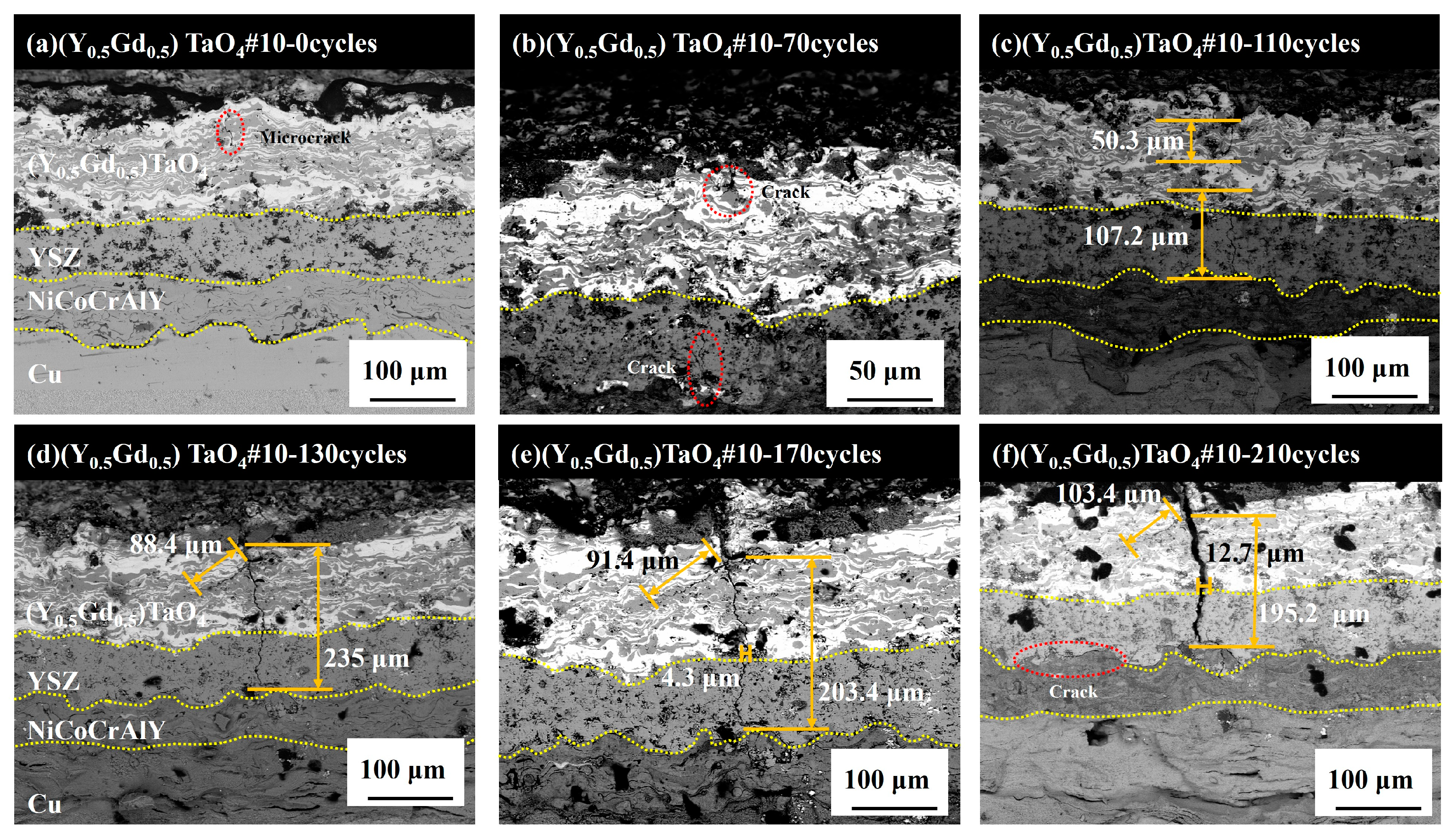
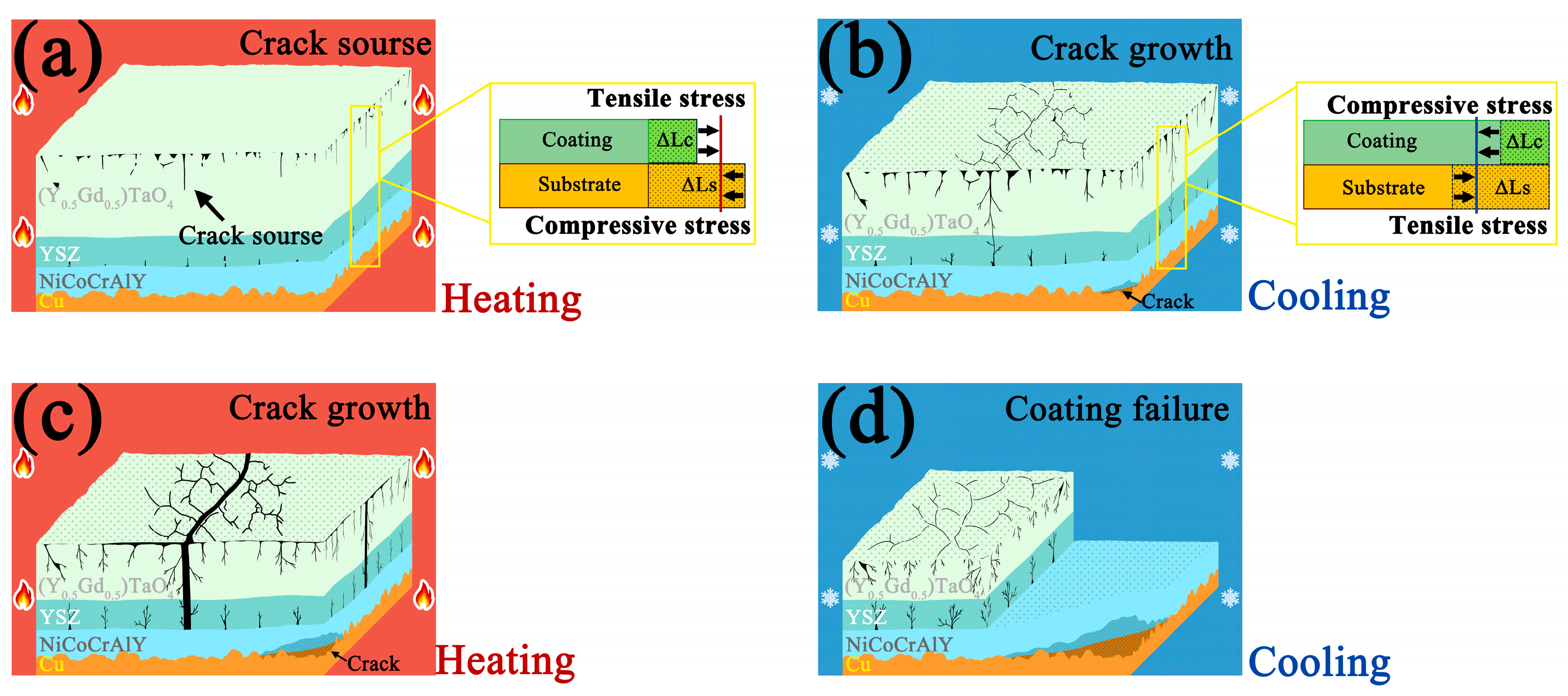
The failure of the 8YSZ/(Y0.5Gd0.5)TaO4 double-ceramic-layer thermal barrier coatings is crack growth due to thermal stress mismatch accumulation during thermal cycling.
(3)
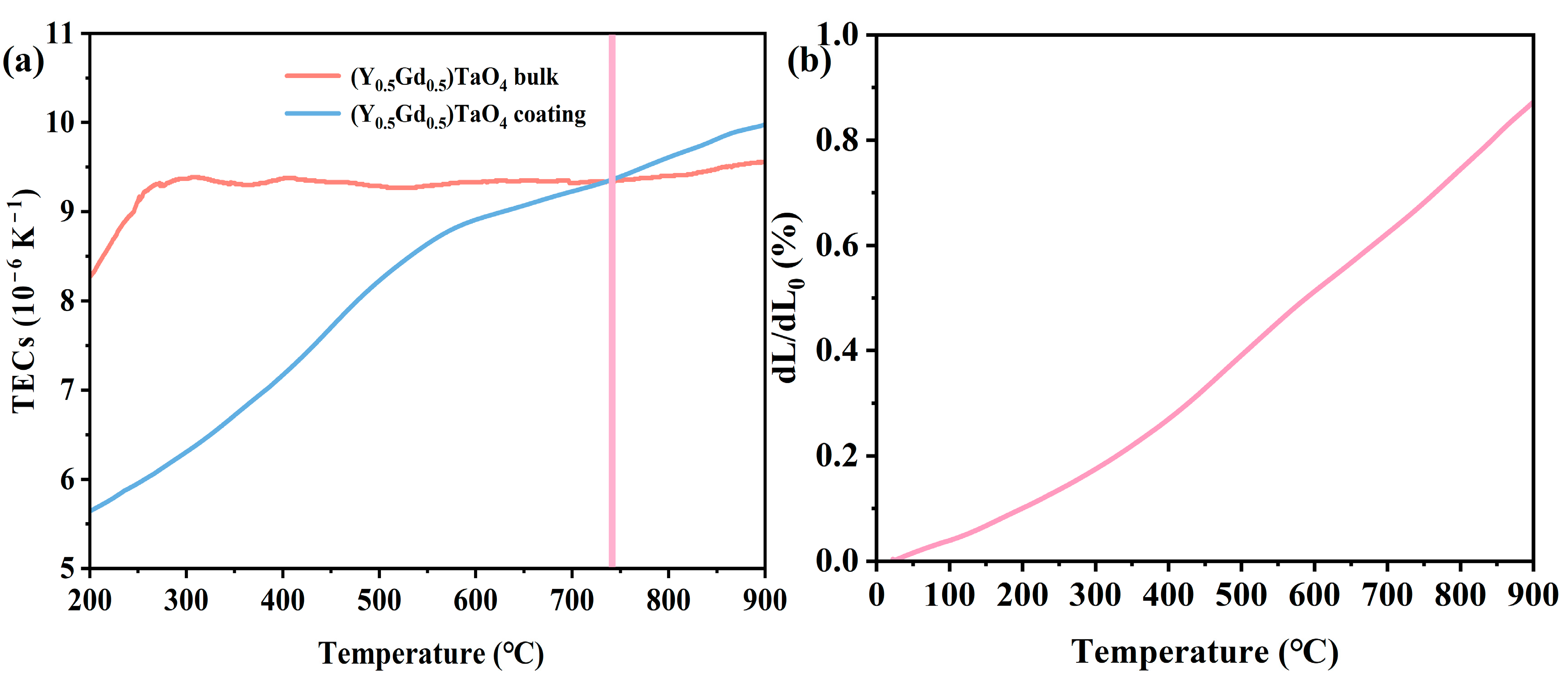
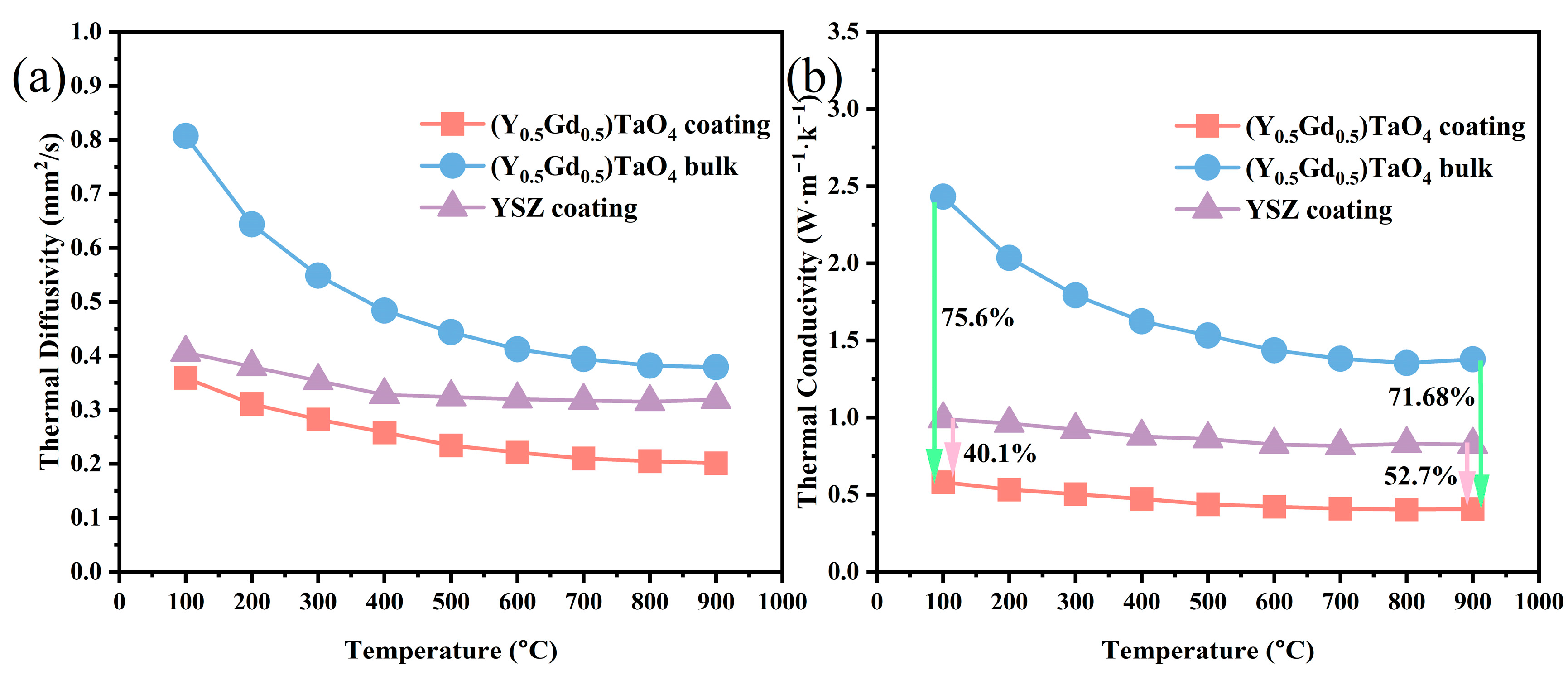
The TECs of the (Y0.5Gd0.5)TaO4 coatings and dense blocks are close to each other when the temperature exceeds 740 °C, benefiting from the pores and cracks being sintered and compacted under the compressive thermal stress at high temperatures. The thermal conductivity (0.39 W·m−1·K−1 at 900 °C) of (Y0.5Gd0.5)TaO4 coating is 71.68% and 52.7% lower than that of the (Y0.5Gd0.5)TaO4 bulk and 8YSZ.
(4)
The phase transition of T mixed   phase   of   T   and   M occurs in (Y0.5Gd0.5)TaO4 when the heat treatment temperature increases to 1000 °C, 1100 °C, 1200 °C, 1300 °C, and 1400 °C for 6 h, respectively; the phase transition of mixed   phase   of   T   and   M M occurs in (Y0.5Gd0.5)TaO4 when the heat treatment temperature to 1400 °C for 12 h.
(5)
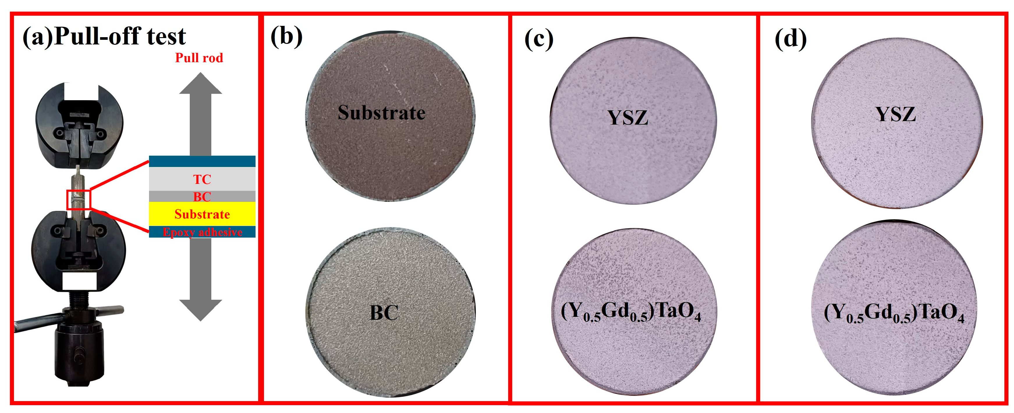
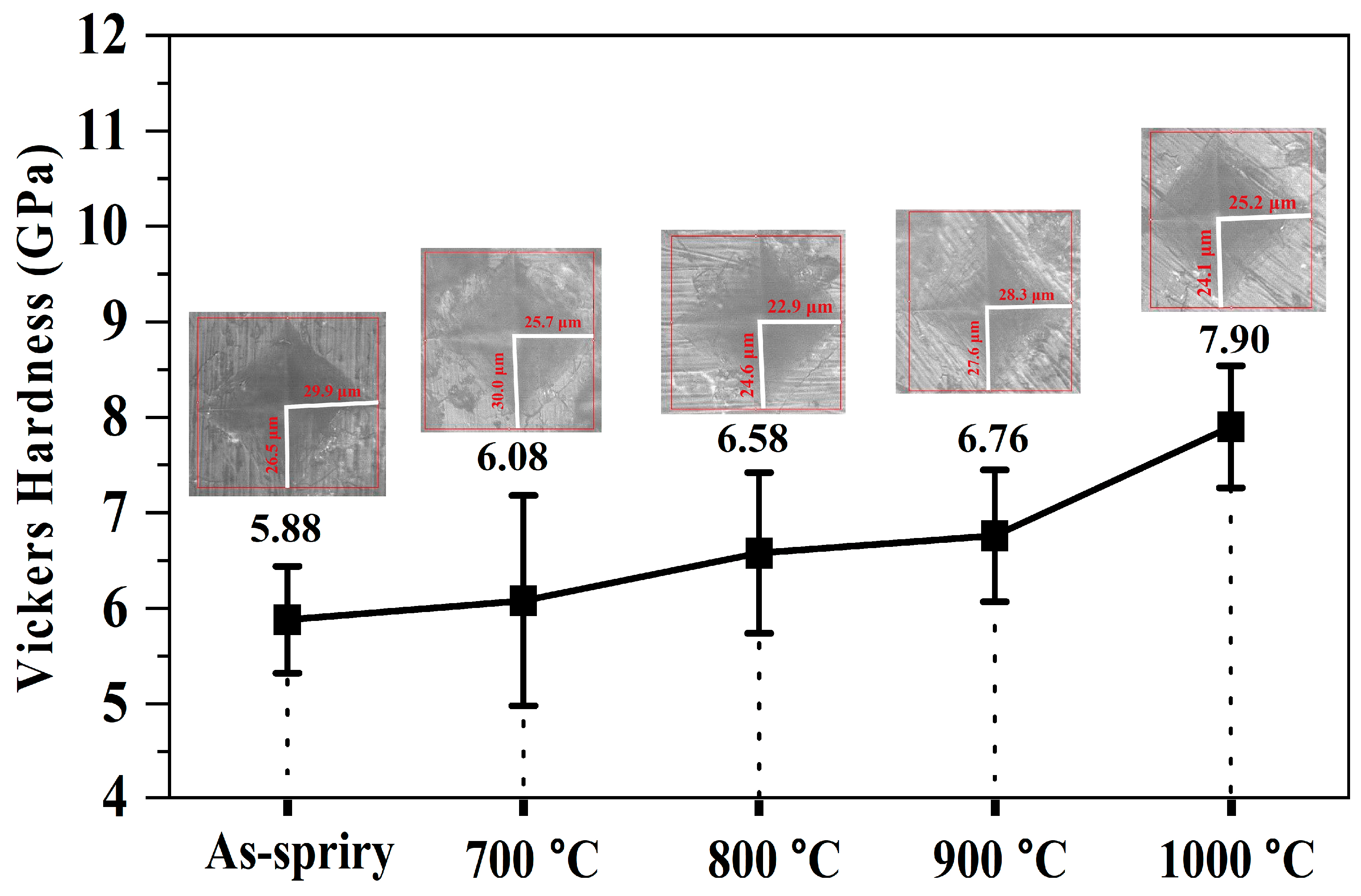
Heat treatment improves the mechanical properties of the coating. The bond strength increases from 8.86 MPa to 14.03 MPa when the heat treatment time increases to 24 h at 500 °C and the hardness improves from 5.88 ± 0.56 GPa to 7.90 ± 0.64 GPa when the heat treatment temperature increases to 1000 °C for 6 h.

Author Contributions

Writing—review and editing, X.Z., Q.J. and J.W.; writing—original draft, investigation, X.Z. and Q.J.; validation: J.F.; investigation, X.Z., J.M., H.L. and Q.J.; supervision, J.W. and J.F.; data curation, X.Z. and Q.J.; conceptualization, J.W. and J.F.; funding acquisition, Q.J. and J.W.; methodology, J.M., H.L. and J.F.; formal analysis, J.M., H.L. and J.W. All authors will be updated at each stage of manuscript processing, including submission, revision, and revision reminder, via emails from our system or the assigned Assistant Editor. All authors have read and agreed to the published version of the manuscript.

Funding

This research was funded by the National Natural Science Foundation of China (52402077), Yunnan Fundamental Research Projects (202501AU070113), Open Project of Yunnan Precious Metals Laboratory (YPML-2023050240), Yunnan Fundamental Research Projects (202201BE070001-008), Yunnan Fundamental Research Projects (202305AS350018).

Institutional Review Board Statement

Not applicable.

Informed Consent Statement

Not applicable.

Data Availability Statement

Data are contained within the article.

Conflicts of Interest

The authors declare that they have no known competing financial interests or personal relationships that could have appeared to influence the work reported in this paper.

References

  1. Chatterjee, R.; Nag, S.; Kundu, S.; Ghosh, U.; Singh, U.; Chandra, S. Impact of Flow Boiling on Blast Furnace Tuyere Life: A Designer’s Perspective. Steel Res. Int. 2022, 93, 2100567. [Google Scholar] [CrossRef]
  2. Zhang, J.; Wang, R.D.; Hu, R.; Zhang, C.; Li, G.S.; Zhang, Y.W.; Wu, W.H.; Lu, X.G. Failure mode and mechanism of a blast furnace tuyere. Eng. Fail. Anal. 2022, 137, 106294. [Google Scholar] [CrossRef]
  3. Zhu, W.; Zhang, J.; Zong, Y.; Zhang, L.; Liu, Y.; Yan, L.; Jiao, K. Optimization Study of Annular Wear-Resistant Layer Structure for Blast Furnace Tuyere. Metals 2023, 13, 1109. [Google Scholar] [CrossRef]
  4. Kumar Das, B. Reduction in heat losses through air tuyeres in blast furnaces at DSP. Mater. Today Proc. 2022, 66, 3944–3948. [Google Scholar] [CrossRef]
  5. Zhang, C.; Hu, R.; Wu, W.; Zhang, Y.; Wang, D.; Zhang, P.; Chen, Z.; Lu, X. A novel device for investigating the anti-melting loss performance of Ni60A coating on coppery tuyere. Mater. Lett. 2024, 364, 136299. [Google Scholar] [CrossRef]
  6. Pathak, A.; Sivakumar, G.; Prusty, D.; Shalini, J.; Dutta, M.; Joshi, S.V. Thermal Spray Coatings for Blast Furnace Tuyere Application. J. Therm. Spray Technol. 2015, 24, 1429–1440. [Google Scholar] [CrossRef]
  7. Goloshchapov, K.V.; Kobelev, O.A.; Titlyanov, A.E.; Borisov, P.V.; Makarov, P.S.; Chicheneva, O.N. Improvement of the Function of Blast-Furnace Air Tuyeres. Metallurgist 2022, 66, 215–220. [Google Scholar] [CrossRef]
  8. Konrad, W.; Adam, J.; Konietzko, S.; Neinhuis, C. When Lotus Leaves Prevent Metal from Melting—Biomimetic Surfaces for High Temperature Applications. J. Bionic Eng. 2019, 16, 281–290. [Google Scholar] [CrossRef]
  9. Baby Raga Malikasri, N.; Kishore, K.; Singh Arora, K.; Shankar Mahobia, G. Failure mechanisms of blast furnace tuyeres and mitigation strategies: A comprehensive review. Eng. Fail. Anal. 2025, 167, 108968. [Google Scholar] [CrossRef]
  10. Pitek, F.M.; Levi, C.G. Opportunities for TBCs in the ZrO2–YO1.5–TaO2.5 system. Surf. Coat. Technol. 2007, 201, 6044–6050. [Google Scholar] [CrossRef]
  11. Limarga, A.M.; Shian, S.; Leckie, R.M.; Levi, C.G.; Clarke, D.R. Thermal conductivity of single- and multi-phase compositions in the ZrO2-Y2O3-Ta2O5 system. J. Eur. Ceram. Soc. 2014, 34, 3085–3094. [Google Scholar] [CrossRef]
  12. Siqueira, K.P.F.; Carvalho, G.B.; Dias, A. Influence of the processing conditions and chemical environment on the crystal structures and phonon modes of lanthanide orthotantalates. Dalton Trans. 2011, 40, 9454–9460. [Google Scholar] [CrossRef] [PubMed]
  13. Qu, C.K.; Chen, L.; Lv, L.; Wang, Y.C.; Ji, X.L.; Yun, H.T.; Su, C.Q.; Feng, J. Low thermal conductivity and anisotropic thermal expansion of ferroelastic (Gd1-xYx)TaO4 ceramics. J. Adv. Ceram. 2022, 11, 1696–1713. [Google Scholar] [CrossRef]
  14. Li, Y.; Wang, K.; Fu, H.; Zhi, X.; Guo, X.; Lin, J. Prediction for Dilution Rate of AlCoCrFeNi Coatings by Laser Cladding Based on a BP Neural Network. Coatings 2021, 11, 1402. [Google Scholar] [CrossRef]
  15. Zalnezhad, E.; Sarhan, A.A.D.; Hamdi, M. Optimizing the PVD TiN thin film coating’s parameters on aerospace AL7075-T6 alloy for higher coating hardness and adhesion with better tribological properties of the coating surface. Int. J. Adv. Manuf. Technol. 2013, 64, 281–290. [Google Scholar] [CrossRef]
  16. ISO 4624:2002; Paints and Varnishes—Pull-Off Test for Adhesion. German Version EN ISO 4624:2003; International Organization for Standardization: Geneva, Switzerland, 2002.
  17. Abbas, M.; Guo, L.; Guo, H. Evaluation of stress distribution and failure mechanism in lanthanum–titanium–aluminum oxides thermal barrier coatings. Ceram. Int. 2013, 39, 5103–5111. [Google Scholar] [CrossRef]
  18. Wang, L.; Wang, Y.; Sun, X.G.; He, J.Q.; Pan, Z.Y.; Wang, C.H. Thermal shock behavior of 8YSZ and double-ceramic-layer La2Zr2O7/8YSZ thermal barrier coatings fabricated by atmospheric plasma spraying. Ceram. Int. 2012, 38, 3595–3606. [Google Scholar] [CrossRef]
  19. Liu, G.-L.; Zhu, L.; Li, X.-Y.; Sajjad, H.; Song, X.-Y.; Li, G.-R.; Yang, G.-J. Achieving durable double-layered thermal barrier coatings by tailoring multi-scale structures. J. Adv. Ceram. 2024, 13, 2068–2086. [Google Scholar] [CrossRef]
  20. Sarikaya, O. Effect of some parameters on microstructure and hardness of alumina coatings prepared by the air plasma spraying process. Surf. Coat. Technol. 2005, 190, 388–393. [Google Scholar] [CrossRef]
  21. Tillmann, W.; Khalil, O.; Baumann, I. Influence of spray gun parameters on inflight particle’s characteristics, the splat-type distribution, and microstructure of plasma-sprayed YSZ coatings. Surf. Coat. Technol. 2021, 406, 126705. [Google Scholar] [CrossRef]
  22. Friis, M.; Persson, C.; Wigren, J. Influence of particle in-flight characteristics on the microstructure of atmospheric plasma sprayed yttria stabilized ZrO2. Surf. Coat. Technol. 2001, 141, 115–127. [Google Scholar] [CrossRef]
  23. Sun, G.; He, X.; Jiang, J.; Sun, Y. Parametric study of Al and Al2O3 ceramic coatings deposited by air plasma spray onto polymer substrate. Appl. Surf. Sci. 2011, 257, 7864–7870. [Google Scholar] [CrossRef]
  24. Limarga, A.M.; Vaßen, R.; Clarke, D.R. Stress Distributions in Plasma-Sprayed Thermal Barrier Coatings Under Thermal Cycling in a Temperature Gradient. J. Appl. Mech. 2010, 78, 011003. [Google Scholar] [CrossRef]
  25. Zhao, Y.; Li, D.; Zhong, X.; Zhao, H.; Wang, L.; Shao, F.; Liu, C.; Tao, S. Thermal shock behaviors of YSZ thick thermal barrier coatings fabricated by suspension and atmospheric plasma spraying. Surf. Coat. Technol. 2014, 249, 48–55. [Google Scholar] [CrossRef]
  26. Liang, J.; Zhang, M.; Peng, Y.; Wang, J. Advances in Understanding the Evolution Mechanism of Micropore Defects in Metal Materials under External Loads. Metals 2024, 14, 522. [Google Scholar] [CrossRef]
  27. Wang, Y.; Tian, W.; Yang, Y.; Li, C.G.; Wang, L. Investigation of stress field and failure mode of plasma sprayed Al2O3–13%TiO2 coatings under thermal shock. Mater. Sci. Eng. A 2009, 516, 103–110. [Google Scholar] [CrossRef]
  28. Feng, J.; Wang, J.; Yang, K.L.; Rong, J. Microstructure and performance of YTaO4 coating deposited by atmospheric plasma spraying on TC4 titanium alloy surface. Surf. Coat. Technol. 2022, 431, 128004. [Google Scholar] [CrossRef]
  29. Moghaddam, K.S.; Usher, J.S. Sensitivity analysis and comparison of algorithms in preventive maintenance and replacement scheduling optimization models. Comput. Ind. Eng. 2011, 61, 64–75. [Google Scholar] [CrossRef]
  30. Scrivani, A.; Rizzi, G.; Bardi, U.; Giolli, C.; Miranda, M.M.; Ciattini, S.; Fossati, A.; Borgioli, F. Thermal Fatigue Behavior of Thick and Porous Thermal Barrier Coatings Systems. J. Therm. Spray Technol. 2007, 16, 816–821. [Google Scholar] [CrossRef]
  31. Wu, M.; Liu, Y.; Qu, W.; Guo, W.; Zhang, H.; Pei, Y.; Li, S.; Gong, S. Thickness-related failure behaviors of the thermal barrier coatings under thermal gradient cycling. Surf. Coat. Technol. 2023, 468, 129748. [Google Scholar] [CrossRef]
  32. Wang, C.; Li, K.; Shi, X.; Huo, C.; He, Q.; Zhang, Y. Effect of spraying power on oxidation resistance and mechanical properties of plasma sprayed La-Mo-Si coating. Surf. Coat. Technol. 2017, 311, 138–150. [Google Scholar] [CrossRef]
  33. Sudharshan Phani, P.; Srinivasa Rao, D.; Joshi, S.V.; Sundararajan, G. Effect of Process Parameters and Heat Treatments on Properties of Cold Sprayed Copper Coatings. J. Therm. Spray Technol. 2007, 16, 425–434. [Google Scholar] [CrossRef]
  34. Wang, J.; Zheng, Q.; Shi, X.L.; Li, D.B.; Yang, Y.; Li, C.; Feng, J. Microstructural evolution and thermal-physical properties of YTaO4 coating after high-temperature exposure. Surf. Coat. Technol. 2023, 456, 129222. [Google Scholar] [CrossRef]
  35. Shian, S.; Sarin, P.; Gurak, M.; Baram, M.; Kriven, W.M.; Clarke, D.R. The tetragonal-monoclinic, ferroelastic transformation in yttrium tantalate and effect of zirconia alloying. Acta Mater. 2014, 69, 196–202. [Google Scholar] [CrossRef]
  36. Macauley, C.A.; Fernandez, A.N.; Levi, C.G. Phase equilibria in the ZrO2-YO1.5-TaO2.5 system at 1500 °C. J. Eur. Ceram. Soc. 2017, 37, 4888–4901. [Google Scholar] [CrossRef]
  37. Flamant, Q.; Gurak, M.; Clarke, D.R. The effect of zirconia substitution on the high-temperature transformation of the monoclinic-prime phase in yttrium tantalate. J. Eur. Ceram. Soc. 2018, 38, 3925–3931. [Google Scholar] [CrossRef]
  38. Feng, J.; Shian, S.; Xiao, B.; Clarke, D.R. First-principles calculations of the high-temperature phase transformation in yttrium tantalate. Phys. Rev. B 2014, 90, 094102. [Google Scholar] [CrossRef]
  39. Wang, J.; Jin, Q.; Song, J.; Zhang, D.; Xu, B.; Ren, Z.; Wang, M.; Yan, S.; Sun, X.; Liu, C.; et al. Revealing the low thermal conductivity of high-entropy rare-earth tantalates via multi-scale defect analysis. J. Adv. Ceram. 2023, 12, 2087–2100. [Google Scholar] [CrossRef]
  40. Wang, J.; Zeng, Y.; Chong, X.; Zhang, M.; Jin, Q.; Sun, Y.; Tang, X.; Wu, P.; Feng, J. Superior thermal and oxygen barrier properties of high-entropy ferroelastic rare earth tantalate (8RE1/8)TaO4. J. Adv. Ceram. 2024, 13, 2051–2067. [Google Scholar] [CrossRef]
  41. Wang, S.; Wang, Y.; Chen, G.; Zhang, H.; Zou, Y.; Ye, Z.; Ouyang, J.; Jia, D.; Zhou, Y. High-temperature broadband infrared radiation from rare earth monosilicate-based ceramics. J. Eur. Ceram. Soc. 2024, 44, 6510–6517. [Google Scholar] [CrossRef]
  42. Cernuschi, F.; Ahmaniemi, S.; Vuoristo, P.; Mäntylä, T. Modelling of thermal conductivity of porous materials: Application to thick thermal barrier coatings. J. Eur. Ceram. Soc. 2004, 24, 2657–2667. [Google Scholar] [CrossRef]
  43. Wang, S.; Ye, Z.; Zhang, H.; Wang, Y.; Zhang, T.; Zou, Y.; Ouyang, J.; Jia, D.; Zhou, Y. High-entropy strategy for high-temperature broadband infrared radiation and low thermal conductivity. Ceram. Int. 2024, 50, 18806–18813. [Google Scholar] [CrossRef]
  44. Wang, S.; Zhang, H.; Wang, Y.; Chen, G.; Zou, Y.; Wang, M.; Zhao, D.; Jin, R.; Ouyang, J.; Jia, D.; et al. Doping engineering for high-temperature broadband high emissivity and low thermal conductivity of ytterbium chromate-based ceramics. Ceram. Int. 2024, 50, 17657–17664. [Google Scholar] [CrossRef]
  45. Moteb, A.; Chen, K. Modelling and evaluating thermal conductivity of porous thermal barrier coatings at elevated temperatures. Ceram. Int. 2020, 46, 21939–21957. [Google Scholar] [CrossRef]
  46. Qu, Z.; Zhang, T.; Pan, W. Defect chemistry and thermal conductivity of the εSmO1.5·(1−ε)ZrO2 (0.2 ≤ ε ≤ 0.65) ceramics: Effect of the nonstoichiometry. J. Adv. Ceram. 2024, 13, 1823–1834. [Google Scholar] [CrossRef]
  47. Wang, J.; Chen, L.; Li, B.; Xu, H.; Jiang, X.; Li, J.-F.; Feng, J. Evolutions of mechanical and thermal properties of TmNbO4/Tm3NbO7 composites as protective coating materials. J. Adv. Ceram. 2024, 13, 1771–1785. [Google Scholar] [CrossRef]
  48. Godiganur, V.S.; Nayaka, S.; Kumar, G.N. Thermal barrier coating for diesel engine application—A review. Mater. Today Proc. 2021, 45, 133–137. [Google Scholar] [CrossRef]
  49. Zhang, P.; Liu, X.-J.; He, G.-Y.; Chiang, F.-K.; Wang, H.; Wu, Y.; Jiang, S.-H.; Zhang, X.-B.; Lu, Z.-P. Novel high-entropy ultra-high temperature ceramics with enhanced ablation resistance. Rare Met. 2024, 43, 6559–6570. [Google Scholar] [CrossRef]
  50. Dharuman, N.; Arulmozhi, M.; Babu, M.S.; Berchmans, L.J.; Sreedhar, G. Investigations on oxidation, hot corrosion and thermal gradient performance of low k-La2Mo2O9 thermal barrier coating. Bull. Mater. Sci. 2021, 44, 8. [Google Scholar] [CrossRef]
  51. Karaoglanli, A.C.; Dikici, H.; Kucuk, Y. Effects of heat treatment on adhesion strength of thermal barrier coating systems. Eng. Fail. Anal. 2013, 32, 16–22. [Google Scholar] [CrossRef]
  52. Paul, S. Assessing Coating Reliability Through Pore Architecture Evaluation. J. Therm. Spray Technol. 2010, 19, 779–786. [Google Scholar] [CrossRef]
  53. Jiang, C.-Y.; Feng, M.; Yu, C.-T.; Bao, Z.-B.; Zhu, S.-L.; Wang, F.-H. Thermal cycling behavior of nanostructured and conventional yttria-stabilized zirconia thermal barrier coatings via air plasma spray. Rare Met. 2023, 42, 3859–3869. [Google Scholar] [CrossRef]
  54. Wang, A.; Li, S.-H.; Bao, H. Thermal transport mechanism of electrons and phonons in pristine and defective HfB2. Rare Met. 2023, 42, 3651–3661. [Google Scholar] [CrossRef]
  55. Liu, Z.; Gao, W.; Dahm, K.L.; Wang, F. Oxidation behaviour of sputter-depositedNi–Cr–Al micro-crystalline coatings. Acta Mater. 1998, 46, 1691–1700. [Google Scholar] [CrossRef]
  56. Naumenko, D.; Pillai, R.; Chyrkin, A.; Quadakkers, W.J. Overview on Recent Developments of Bondcoats for Plasma-Sprayed Thermal Barrier Coatings. J. Therm. Spray Technol. 2017, 26, 1743–1757. [Google Scholar] [CrossRef]
  57. Li, M.H.; Sun, X.F.; Li, J.G.; Zhang, Z.Y.; Jin, T.; Guan, H.R.; Hu, Z.Q. Oxidation Behavior of a Single-Crystal Ni-Base Superalloy in Air. I: At 800 and 900 °C. Oxid. Met. 2003, 59, 591–605. [Google Scholar] [CrossRef]
  58. Brumm, M.W.; Grabke, H.J. The oxidation behaviour of NiAl-I. Phase transformations in the alumina scale during oxidation of NiAl and NiAl-Cr alloys. Corros. Sci. 1992, 33, 1677–1690. [Google Scholar] [CrossRef]
  59. Toscano, J.; Gil, A.; Hüttel, T.; Wessel, E.; Naumenko, D.; Singheiser, L.; Quadakkers, W.J. Temperature dependence of phase relationships in different types of MCrAlY-coatings. Surf. Coat. Technol. 2007, 202, 603–607. [Google Scholar] [CrossRef]
  60. Li, G.; Huang, P.; Cheng, P.; Wu, W.; Zhang, Y.; Pang, Z.; Xu, Q.; Zhu, K.; Zou, X.; Li, R.; et al. Analysis of the failure mechanism of a blast furnace tuyere sleeve with protective coating. Eng. Fail. Anal. 2023, 153, 107537. [Google Scholar] [CrossRef]
  61. Curiotto, S.; Battezzati, L.; Johnson, E.; Pryds, N. Thermodynamics and mechanism of demixing in undercooled Cu–Co–Ni alloys. Acta Mater. 2007, 55, 6642–6650. [Google Scholar] [CrossRef]
Figure 1. The schematic diagram of 8YSZ/(Y0.5Gd0.5)TaO4 double-ceramic-layer thermal barrier coatings on copper substrate.
Coatings 15 00451 g001
Figure 2. The (Y0.5Gd0.5)TaO4 spherical powder: (a) SEM image; (b) particle size distribution measured by laser particle sizer.
Coatings 15 00451 g002
Figure 3. The microstructure of the (Y0.5Gd0.5)TaO4 coatings #1–9: (ai) BSE image; (j) XRD patterns.
Coatings 15 00451 g003
Figure 4. The average mass loss rate and macroscopic coating surface images after 20 thermal cycles at 600 °C.
Coatings 15 00451 g004
Figure 5. The ki value of average mass loss rate after 20 thermal cycles at 600 °C for different spraying parameters: (a) current (A); (b) hydrogen flow rate (L/min); (c) argon flow rate (L/min); (d) spray distance (mm); (e) optimal spraying parameters for the (Y0.5Gd0.5)TaO4 coating #10.
Coatings 15 00451 g005
Figure 6. The microstructure of the (Y0.5Gd0.5)TaO4#10 coating under different conditions of heat treatment: (ad) BSE images after heat treatment at 0 °C, 800 °C, 900 °C, and 1000 °C for 6 h, respectively; (e) XRD patterns.
Coatings 15 00451 g006
Figure 7. The thermal properties of the (Y0.5Gd0.5)TaO4: (a) the TECs of (Y0.5Gd0.5)TaO4 bulk and coating; (b) rate of thermal expansion for (Y0.5Gd0.5)TaO4 coating.
Coatings 15 00451 g007
Figure 8. The thermal properties of (Y0.5Gd0.5)TaO4 bulk and coating, and YSZ coating [50]: (a) thermal diffusivity; (b) thermal conductivity.
Coatings 15 00451 g008
Figure 9. The fractured surface of the (Y0.5Gd0.5)TaO4 coating with various heat treatment times at 500 °C: (a) schematic of the pull-off test; (b) 0 h; (c) 12 h; (d) 24 h.
Coatings 15 00451 g009
Figure 10. The Vickers hardness after heat treatment at various temperatures for 6 h.
Coatings 15 00451 g010
Figure 11. The BSE of (Y0.5Gd0.5)TaO4#10 coating after thermal cycling at 600 °C: (a) 0 cycles; (b) 70 cycles; (c) 110 cycles; (d) 130 cycles; (e) 170 cycles; (f) 210 cycles.
Coatings 15 00451 g011
Figure 12. The BSE and EDS of the TBCs after thermal cycling at 600 °C: (a) 0 cycles; (b) 190 cycles.
Coatings 15 00451 g012
Figure 13. The schematic diagram of thermal cycling failure for NiCoCrAlY/8YSZ/(Y0.5Gd0.5)TaO4. (a) crack source; (b) crack growth; (c) crack growth; (d) coatings failure.
Coatings 15 00451 g013
Table 1. The chemical composition of the NiCrCoAlY alloy powder (wt.%).
ElementNiCrCoAlY
W46.3725.9521.545.630.51
Table 2. The spraying parameters for BC and 8YSZ coatings.
Coating NameI (A)U (V)PHydrogen (L/min)PArgon (L/min)Spring Distance (mm)
NiCoCrAlY420640.8333.33130
8 wt.% YSZ500644.3341.33130
Table 3. The spraying parameters and experimental levels for (Y0.5Gd0.5)TaO4 coatings.
Level (i)I (A)U (V)PHydrogen (L/min)PArgon (L/min)Spring Distance (mm)
1500643.6633.33100
2550644.3338.33130
360064541.33170
Table 4. The spraying parameters for (Y0.5Gd0.5)TaO4 coatings.
SamplesI (A)U (V)PHydrogen (L/min)PArgon (L/min)Spring Distance (mm)
(Y0.5Gd0.5)TaO4#1500643.6633.33100
(Y0.5Gd0.5)TaO4#2500644.3338.33130
(Y0.5Gd0.5)TaO4#350064541.33170
(Y0.5Gd0.5)TaO4#4550644.3333.33170
(Y0.5Gd0.5)TaO4#555064538.33100
(Y0.5Gd0.5)TaO4#6550643.6641.33130
(Y0.5Gd0.5)TaO4#760064533.33130
(Y0.5Gd0.5)TaO4#8600643.6638.33170
(Y0.5Gd0.5)TaO4#9600644.3341.33100
Table 5. The average mass loss rate, ki and R values for different spraying parameters of (Y0.5Gd0.5)TaO4 coatings.
SamplesCurrent (A)Hydrogen Flow Rate (L/min)Argon Flow Rate (L/min)Spray Distance (mm)The Average Mass Loss Rate (‰)
(Y0.5Gd0.5)TaO4#15003.6633.331007.11
(Y0.5Gd0.5)TaO4#25004.3338.331301.68
(Y0.5Gd0.5)TaO4#3500541.331704.40
(Y0.5Gd0.5)TaO4#45504.3333.331704.38
(Y0.5Gd0.5)TaO4#5550538.331005.77
(Y0.5Gd0.5)TaO4#65503.6641.3313012.01
(Y0.5Gd0.5)TaO4#7600533.331308.58
(Y0.5Gd0.5)TaO4#86003.6638.331702.50
(Y0.5Gd0.5)TaO4#96004.3341.331001.94
k14.407.026.694.94---
k27.392.863.317.42---
k34.346.256.113.76---
R9.1413.6210.1210.99---
Table 6. One-way repeated measures and a summary of ANOVA results for spray parameters.
FactorDfSum SqMean SqF Valuep ValueOptimal Parameter
Current254.6827.342.920.07331600 A
Hydrogen flow rate2103.151.557.020.003994.33 L/min
Argon flow rate258.6429.323.190.059238.33 L/min
Spray distance262.949.023.490.04677170 mm
Disclaimer/Publisher’s Note: The statements, opinions and data contained in all publications are solely those of the individual author(s) and contributor(s) and not of MDPI and/or the editor(s). MDPI and/or the editor(s) disclaim responsibility for any injury to people or property resulting from any ideas, methods, instructions or products referred to in the content.

