Article

Temperature and Depth Sensor Based on Fiber Bragg Gratings with Temperature-Compensated Structure in Marine Environment

1
College of Physics and Electronic Engineering, Hainan Normal University, Haikou 571158, China
2
Key Laboratory of Laser Technology and Optoelectronic Functional Materials of Hainan Province, Haikou 571158, China
3
Hainan International Joint Research Center for Semiconductor Lasers, Haikou 571158, China
*
Author to whom correspondence should be addressed.
Coatings 2025, 15(7), 795; https://doi.org/10.3390/coatings15070795
Submission received: 30 May 2025 / Revised: 15 June 2025 / Accepted: 3 July 2025 / Published: 6 July 2025
(This article belongs to the Section Laser Coatings)

Abstract

A fiber Bragg grating (FBG)-based ocean temperature and depth sensor structure is proposed. The pressure sensing section employs a secondary sensitization design comprising a piston and the polycarbonate buffer, while the temperature sensing section utilizes an FBG encapsulated within a metal silver tube, accompanied by a temperature compensation structure. Simulation analyses verify the enhanced sensitivity of the proposed configuration. By selecting suitable materials for the piston, metal tube, and polymer, and optimizing the dimensions of key components, the sensitivity of the bare FBG sensor is significantly improved through the combined effects of the piston, polymer, and metal tube. After optimization, the sensor exhibits a pressure sensitivity of 1.33 nm/MPa and a temperature sensitivity of 102.77 pm/°C, meeting the high-precision detection requirements for ocean temperature and depth sensing. The experimental results show that the temperature sensitivity is 109.9 pm/°C within the temperature range of −5~35 °C, and that the pressure sensitivity is 1.63 nm/MPa within the pressure range of 1~10 MPa. These results confirm that the sensor is well-suited for high-precision ocean temperature and depth measurements.

1. Introduction

The measurement of oceanic physical parameters plays a crucial role in supporting ocean economic development, marine environmental protection, naval operations, and maritime equipment functionality, thereby garnering significant attention from the scientific community. Accurate, real-time, and continuous acquisition of ocean information is an essential capability for any maritime power, for which ocean environmental monitoring is of paramount importance. Ocean behavior can be predicted through the analysis of various parameters [1], with temperature and pressure serving as the fundamental parameters for determining ocean current velocity, density, and heat content. Consequently, temperature and depth sensors constitute indispensable tools in ocean exploration, underpinning advancements in ocean economy, marine ecology, and maritime defense [2,3].
Expendable Bathythermographs (XBTs) [4] and Conductivity Temperature Depth (CTD) instruments [5] are the primary instruments currently used for measuring seawater temperature and depth. XBTs, as single-use ocean sensors, cannot be reused and typically yield data with lower accuracy compared to CTDs; although, they offer advantages such as low cost, simple operation, and the capability for large-area surveys. Traditional XBTs lack integrated pressure sensors and have historically relied on empirical time–displacement relationships of the probe to estimate its position at any given moment [2]. Although some studies have attempted to improve these empirical models by optimizing the probe’s deployment angle, casing shape, and water-entry orientation [6], they still struggle to overcome the complexities introduced by the varying ocean currents in different regions. To address the absence of pressure sensors in conventional designs, certain approaches have incorporated dedicated pressure-sensing structures to independently acquire depth data [7,8]. In these cases, synchronizing the acquisition times of temperature and depth data is crucial; significant discrepancies may lead to a drift between temperature and depth measurements, thereby substantially lowering the sensor’s overall accuracy [2]. Moreover, traditional electrical temperature sensors used in XBTs—such as platinum resistors and thermistors—suffer from issues including low sensitivity [9], slow response times [10], and poor thermal stability [11]. In contrast, fiber Bragg gratings (FBGs) have been widely employed in ocean sensing over recent years as effective strain and temperature measurement elements due to their compact size [12], high-temperature endurance [13], corrosion resistance [14], immunity to electromagnetic interference [15], low transmission loss [16], additional corrosion resistance [17], and electrical insulation coupled with immunity to electromagnetic interference [18].
However, since bare fiber Bragg gratings exhibit low sensitivity and are therefore unsuitable for high-precision detection applications, various sensitization techniques have been developed to enhance both their temperature and pressure responses. Common encapsulation methods include temperature-sensitive metal or polymer packaging, melt coating, and chemical plating. For example, in 2019, Yan encapsulated an FBG with aluminum and conducted experiments in the 10–60 °C range; the results demonstrated a temperature sensitivity of 40.4 pm/°C, which is four times that of a standard FBG [19]. In 2023, Long proposed an FBG-based temperature sensor with a substrate packaging structure using an aluminum alloy with a high thermal expansion coefficient. In the −20 °C to 40 °C range the encapsulated FBG sensor exhibited a sensitivity of 27.3 pm/°C—2.7 times that of a bare FBG—with a linearity exceeding 0.99 [20].
For pressure sensitization a variety of approaches have been explored, including the use of elastic diaphragms, polymers, thin-walled cylinders, and corrugated tubes. For instance, in 2016, Gu introduced a practical hydraulic optical fiber sensor based on a thin-walled cylinder, with experiments conducted from 0 to 16 MPa revealing a pressure sensitivity of 69.4 pm/MPa [21]. In 2021, Hedge developed a pressure sensor by bonding an FBG at the center of a circular diaphragm with temperature compensation, rendering it suitable for high-pressure environments such as rocket propulsion and deep-sea applications. By employing reference FBG temperature compensation, the sensor accurately measured pressure over a −40 °C to 90 °C temperature range, achieving a pressure sensitivity of 36.4 pm/MPa [22]. For FBG-based ocean temperature and depth sensors, it is crucial not only that the temperature and pressure sensitivities meet the detection requirements, but also that the acquisition of temperature and depth data is synchronized. Moreover, the sensor must operate effectively within the specified range (ocean temperatures from −2 °C to 35 °C) and detection limits. For example, in 2020, Fadeev proposed a sensor incorporating both Fabry–Perot interferometry and an FBG structure for simultaneous pressure and temperature measurement. The sensor achieved a pressure sensitivity of 50 nm/bar, with the Fabry–Perot component exhibiting a temperature sensitivity of 4.6 nm/°C and the FBG component 10 pm/°C [23]. Although this design permits concurrent measurement of both parameters, its sensitivity advantages are limited. In 2022, Liu presented a temperature and depth sensor based on a diaphragm and liquid-filled structure, which enhanced the sensitivity of two FBGs through thermal expansion and diaphragm deformation. In a sensing range of 0–8 MPa, the sensor achieved a temperature sensitivity of 1.065 nm/°C and a pressure sensitivity of 1.245 nm/MPa, with response times of approximately 51 ms. This sensor significantly improved both the temperature and depth sensitivity and ensured synchronized acquisition of the two parameters, although its response speed remained relatively slow. The same year, Zhao proposed an all-fiber XBT based on a cascaded configuration of two fiber Bragg gratings, which achieved average temperature sensitivities of the two sensors of 14.765 and 13.705 pm/°C within the temperature range of 5~30 °C, respectively, and the average pressure sensitivities were −2.75586 nm/MPa and −3.00472 nm/MPa within the pressure range of 0~0.6 MPa [24]. Although the pressure sensitivity is relatively high, this sensor is only capable of measuring depths up to 60 m. However, while pursuing higher pressure sensitivity, FBGs are also sensitive to temperature, and temperature fluctuations can distort pressure readings. Therefore, after designing a pressure-sensitizing structure, it is essential to incorporate a temperature-compensation mechanism to ensure accurate pressure measurement. The common temperature-compensation methods include fully pasted FBGs and metallic-packaged FBGs [25]. For example, in 2019, Hopf et al. glued two polarization-maintaining FBGs onto a rigid aluminum substrate using thermosetting epoxy and employed wavelength difference measurement for compensation [26]. In 2021, Hegde et al. bonded two FBGs to the two surfaces of a martensitic stainless-steel diaphragm and used their wavelength difference for temperature compensation. In the same year, Fajkus et al. attached the pressure-sensing FBG and the temperature-compensation FBG and applied pre-strain to both gratings during installation, utilizing wavelength difference for compensation [27]. Additionally, by integrating reference spectral lines within the optical fiber link the system supports on-site remote calibration without the need for factory returns [28,29]. Furthermore, the sensor’s compact and modular design allows for plug-and-play deployment on AUVs or ROVs. It enables remote calibration via optical communication and can be integrated with other FBG-based pressure, temperature, and vibration sensor modules, achieving long-term, unmanned, high-resolution marine observation performance comparable to traditional CTD instruments [30,31].
In view of the above issues, such as low sensitivity, slow response time, and the asynchronous acquisition of temperature and depth data, this paper proposes an ocean temperature and depth sensor based on fiber Bragg gratings. In terms of pressure sensitivity, diaphragm-based designs suffer from limited measurement range due to the diaphragm’s yield strength and are prone to fatigue and nonlinear distortion under repeated loading. Thin-wall cylinder structures require high-precision fabrication and assembly, leading to increased process and labor costs. Bellows-based sensors, while offering high sensitivity, involve complex manufacturing and sealing requirements; under long-term high-pressure cycling, the corrugations may fatigue and crack, and seawater immersion can cause leakage failures. In contrast, a polymer-encapsulated enhancement structure offers a compact footprint, low cost, simple fabrication, and excellent corrosion resistance in marine environments. Moreover, incorporating a piston provides a secondary amplification mechanism that further increases sensitivity while preventing excessive polymer compression and permanent deformation. Therefore, for pressure sensing we employ a dual-stage amplification structure comprising a piston coupled with a polycarbonate buffer layer. For temperature sensitivity, metal-coated or metal-encapsulated FBGs outperform organic-coating approaches, and direct metal encapsulation is simpler than coating techniques. Hence, we adopt high thermal expansion and high thermal conductivity metal cladding, specifically, a silver tube, to enhance the temperature response of the FBG. A temperature compensation scheme is also integrated to eliminate thermal cross-sensitivity in the pressure sensor, thereby further improving its pressure sensitivity. This configuration not only achieves high sensitivity for both temperature and pressure with matched acquisition speeds but also covers the full oceanic temperature range (−2 °C to 35 °C). Additionally, sensitivity and response time can be tuned by adjusting the piston cross-section, polycarbonate thickness, and silver tube radius. We further present mechanical design analysis and finite-element simulations to validate the efficacy of this sensor architecture.

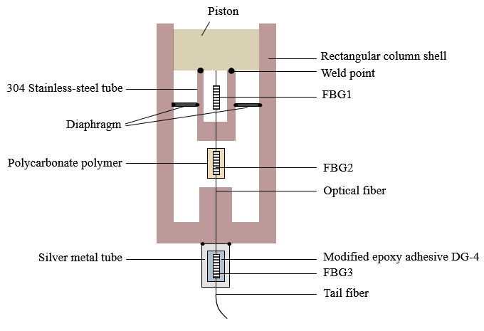
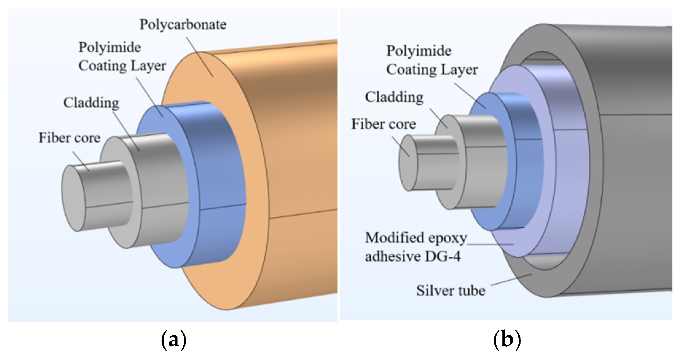
2. Structure Design and Fabrication

The proposed ocean temperature and depth sensor based on cascaded fiber Bragg gratings (FBGs) with temperature compensation structure is illustrated in Figure 1. This sensor consists of two stainless-steel protective casings, a 7075 aluminum alloy piston, one polytetrafluoroethylene (PTFE) diaphragm, a temperature compensation FBG, a pressure-sensing FBG encapsulated in a polycarbonate buffer, and a temperature-sensing FBG encapsulated in a metallic silver tube and coated with modified epoxy adhesive DG-4 (the three FBGs are connected in series along a single optical fiber). The 304 stainless-steel and 7075 aluminum alloy pistons are in direct contact with seawater, requiring consideration of their mechanical stability and corrosion resistance in a marine environment. The 304 stainless-steel exhibits excellent mechanical strength and general corrosion resistance under marine atmospheric conditions and can withstand static pressures up to 10 MPa; however, prolonged immersion may still lead to localized pitting and crevice corrosion. To enhance its corrosion resistance, we applied a polyurethane organic coating to the surface, forming a physical barrier against chloride ingress [32]. Although 7075 aluminum alloy has superior mechanical strength, it is susceptible to localized corrosion under long-term seawater exposure. Therefore, we fabricated a phosphate chemical conversion coating on its surface to establish a protective layer between the substrate and seawater, thereby significantly improving its corrosion resistance [33].
The temperature compensation FBG (FBG1) is positioned inside a 304 stainless-steel tube, the upper end of which is welded to the piston. As the piston moves, FBG1 remains unaffected by pressure and responds solely to internal temperature changes, thereby providing temperature compensation in series with FBG2. By placing FBG1 directly inside the stainless-steel tube without applying or maintaining pre-strain, this design eliminates wavelength drift caused by tension relaxation and fabrication inconsistencies. Meanwhile, the metal tube is integrally welded to the piston end face, avoiding issues such as adhesive aging, relaxation in seawater, and residual stress interference that could affect compensation accuracy. In addition, the overall structure has a diameter of less than 10 mm, offering both high strength and sealing performance, and enabling multi-point, miniaturized deployment suitable for precise deep-sea depth sensing. External hydrostatic pressure acts on the piston, which moves axially and transfers force through a stainless-steel tube to the polycarbonate buffer. When the polycarbonate buffer is compressed radially, it simultaneously develops axial strain that is conveyed to FBG2, causing the fiber to elongate in direct proportion to the external pressure and thereby shift the Bragg wavelength. The polycarbonate buffer’s moderate Young’s modulus ensures sufficient radial compression while maintaining structural stability, amplifying the fiber’s strain response and significantly enhancing pressure sensitivity. To guarantee linearity and repeatability, we applied approximately 0.1% pre-tension to FBG2 during assembly and secured it with epoxy adhesive afterward [34]. At the junction between the piston and the 304 stainless-steel tube, laser welding is employed; FBG2 is led out through small holes in both the stainless-steel housing and the 304 stainless-steel tube and is then fixed in place at the end of the stainless-steel housing using epoxy resin adhesive, thereby securing FBG2. On both sides of the 304 stainless-steel tube, which is directly welded to the 304 stainless-steel housing, a flexible PTFE diaphragm is installed. The PTFE diaphragm has an overall flat structure, with its thickness being much smaller than its length and width. Its central region is divided by the 304 stainless-steel tube into two chambers (left and right); the edges at both ends are fixed to the stainless-steel housing to ensure a proper seal, thereby preventing seawater from infiltrating during piston movement and adversely affecting the measurements. Since PTFE exhibits poor adhesion to metals, we addressed the difficulty by directly bonding PTFE to stainless-steel by roughening the surface of the stainless-steel tube and designing specialized clamping structures or embedded mechanical interfaces. This allows the PTFE to be firmly embedded in or wrapped around the stainless-steel tube; in addition, a specially designed intermediate adhesive—compatible with both PTFE and metal—is used to achieve a stable connection. The temperature-sensing FBG (FBG3) is encapsulated in a metallic silver tube—selected for its high thermal expansion and thermal conductivity—to achieve temperature sensitization. Moreover, FBG3 is bonded to the inner surface of the silver tube using modified epoxy adhesive DG-4 to prevent chirp resulting from the softness of the silver tube. Considering that silver tubes are prone to corrosion in marine environments, an ultra-thin oxide film deposited and coated on the surface of Ag by ALD can improve the anti-corrosion effect of Ag. ALD deposition of alumina is a mature process, and previous studies have demonstrated that ALD-deposited alumina is highly effective in protecting metals or ceramics from corrosion or chemical etching [35].
The fiber tail is fixed to the stainless-steel grade 304 casing using epoxy adhesive. In addition, the pressure-sensing FBG is composed of a core, cladding, and a polyimide coating, with the entire FBG encapsulated in a polycarbonate buffer, as shown in Figure 2a. Similarly, the temperature-sensing FBG consists of a core, cladding, and a polyimide coating; it is coated with the anti-chirp modified epoxy adhesive DG-4 and further encapsulated by a metallic silver tube, as depicted in Figure 2b.

2.1. Temperature Sensing Principle

When the ambient temperature changes, the temperature-sensing FBG (FBG3) is influenced by both the thermal expansion effect and the thermo-optic effect, which cause variations in the effective refractive index of its waveguide and its grating period. Thus, under a change in temperature (ΔT), the wavelength shifts in FBG3 are given by the following:
Δ λ = 2 Δ T n e f f Λ α + 2 Δ T n e f f Λ ξ
where α is the linear expansion coefficient of FBG3, ξ is the thermo-optic coefficient of FBG3, Δ T is the temperature change, n e f f is the effective refractive index of FBG3, and Λ is the grating period of FBG3. Since FBG3 is encapsulated within a metallic silver tube and its strain is enhanced via thermal expansion, K T is defined as the temperature sensitivity of FBG3, which can be expressed as follows:
K T = Δ λ Δ T = 2 n e f f Λ α + 2 n e f f Λ ξ
Equation (2) indicates that the temperature sensitivity of FBG3 depends solely on the material properties of FBG3; therefore, materials with high thermal expansion and high thermal conductivity should be selected for encapsulation. Although the linear expansion coefficient and the thermo-optic coefficient of FBG3 are temperature functions, their variations are minimal, so FBG3 generally exhibits good linearity for temperature sensing.

2.2. Temperature Compensation Principle

Since the pressure-sensing FBG (FBG2) is influenced by both the pressure applied by the piston and the temperature changes within the housing, its wavelength shift is jointly determined by stress and temperature variations. To resolve this temperature–stress cross-sensitivity issue, a temperature compensation method is adopted. Specifically, an additional temperature compensation FBG (FBG1) is installed inside the housing; its wavelength shift is affected solely by the temperature change inside the housing and experiences the same temperature variation as FBG2. The wavelength shifts in FBG2, influenced simultaneously by strain ( ε ) and temperature change ( Δ T 2 ), can be expressed as [36] follows:
λ B 2 λ B 2 = 1 Ρ e ε + [ 1 Ρ e α + ξ ] Δ T 2
FBG1 is sensitive solely to temperature; therefore, its wavelength shifts due to temperature change can be written as follows:
λ B 1 λ B 1 = [ 1 Ρ e α + ξ ] Δ T 1
Since these two FBGs are subjected to the same temperature environment, Δ T 1 = Δ T 2 = Δ T , Equations (3) and (4) can be simplified as follows:
Δ λ B 2 = K P Δ P + K T 2 Δ T
Δ λ B 1 = K T 1 Δ T
where K P and K T 2 denote the pressure sensitivity and temperature sensitivity of FBG2, respectively, and K T 1 represents the temperature sensitivity of FBG1. Thus, by substituting this into Equation (5), one obtains the following:
λ B 2 = K P Δ P + K T 2 λ B 1 K T 1
Equation (7) shows that the temperature-induced error in the pressure measurement is eliminated, thereby achieving temperature compensation.
Overall, both temperature and pressure affect the Bragg wavelength of an FBG: pressure induces mechanical deformation of the grating while temperature alters the grating parameters via thermal expansion and changes in the refractive index. When only a single FBG (FBG1) is employed, it is impossible to distinguish whether a measured wavelength shift arises from temperature or from pressure. To resolve this ambiguity, we introduce a second grating (FBG2) located in the same thermal environment but isolated from mechanical load; FBG2 responds solely to temperature variations. Thus, by subtracting the temperature-induced wavelength shift recorded by FBG2 from the total wavelength shift observed in FBG1, one obtains the pressure-induced component alone, thereby decoupling temperature and pressure effects. It should be noted, however, that this temperature-compensation approach has limitations under conditions of extreme thermal gradients or rapid pressure transients; during swift temperature changes, the finite response time of FBG1 to temperature can result in lagged compensation signals, leading to over- or under-compensation during rapid heating or cooling phases [37]. Such lag errors may be mitigated by refining the temperature-compensation function to account for dynamic response characteristics [38].

2.3. Pressure Sensing Principle

When seawater exerts pressure on the piston, the piston drives the 304 stainless-steel tube to apply axial pressure to the pressure-sensing FBG (FBG2), causing an axial strain in FBG2 that alters its grating period; here, ε can be expressed as follows:
ε = Δ Λ Λ = Δ x x
where Δ x represents the deformation of FBG2 and x denotes its effective length. In addition, the strain in FBG2 also alters its effective refractive index, which can be expressed as follows:
Δ n e f f n e f f = 1 2 n e f f 2 p 12 μ p 12 + p 11 · ε
where p 11 and p 12 are the elasto-optic coefficients of the fiber and μ is the Poisson’s ratio of the fiber material. The effective elasto-optic coefficient is then given by the following:
P e = 1 2 n e f f 2 p 12 μ p 12 + p 11          
By combining the above equations, the wavelength shift induced by axial strain can be expressed as follows:
Δ λ b = 1 P e λ · ε
For an FBG with a fixed central wavelength and fixed material properties, the wavelength drift depends solely on the strain experienced by the FBG; therefore, FBG2 can be employed for pressure sensing.

3. Results and Discussion

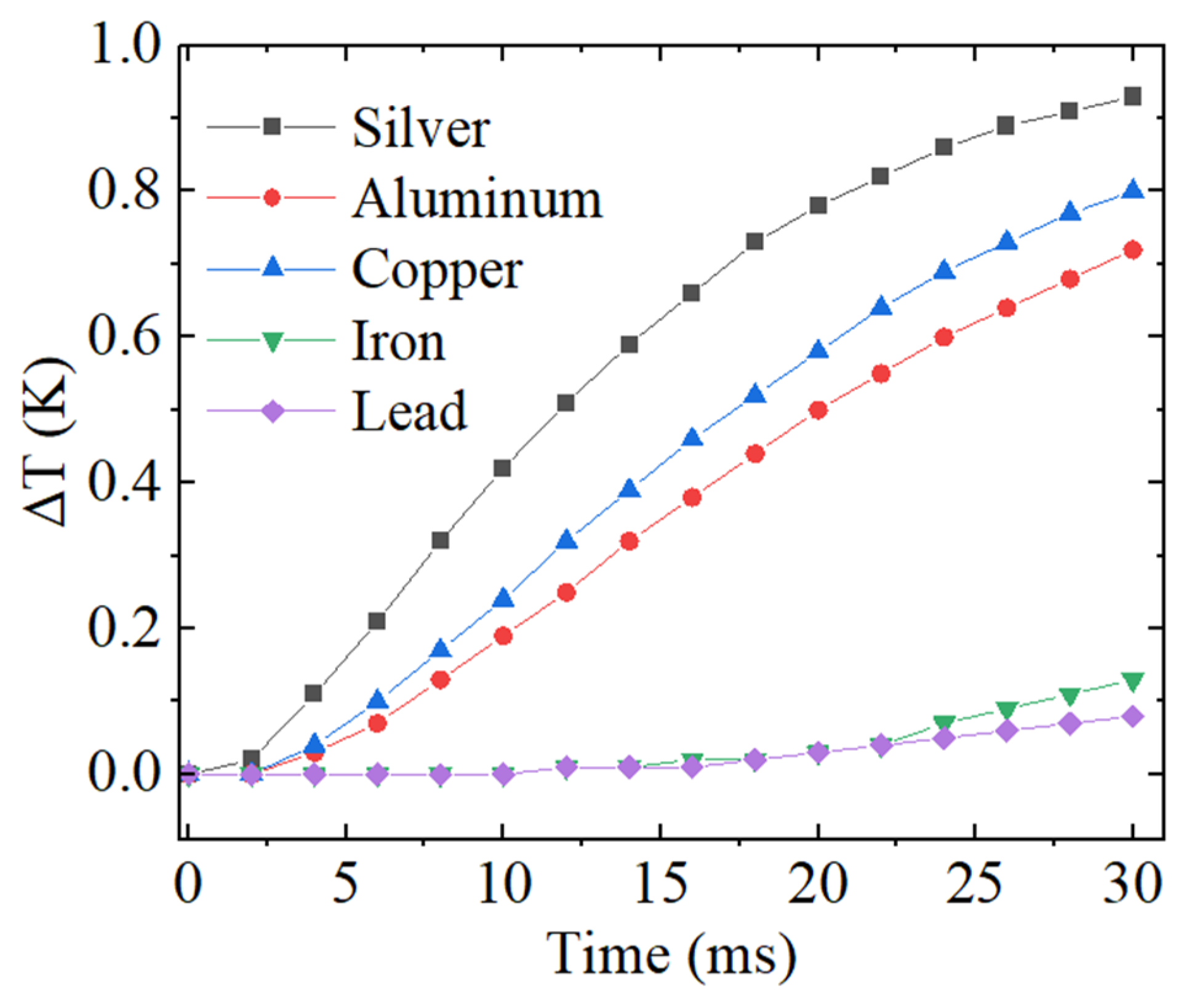
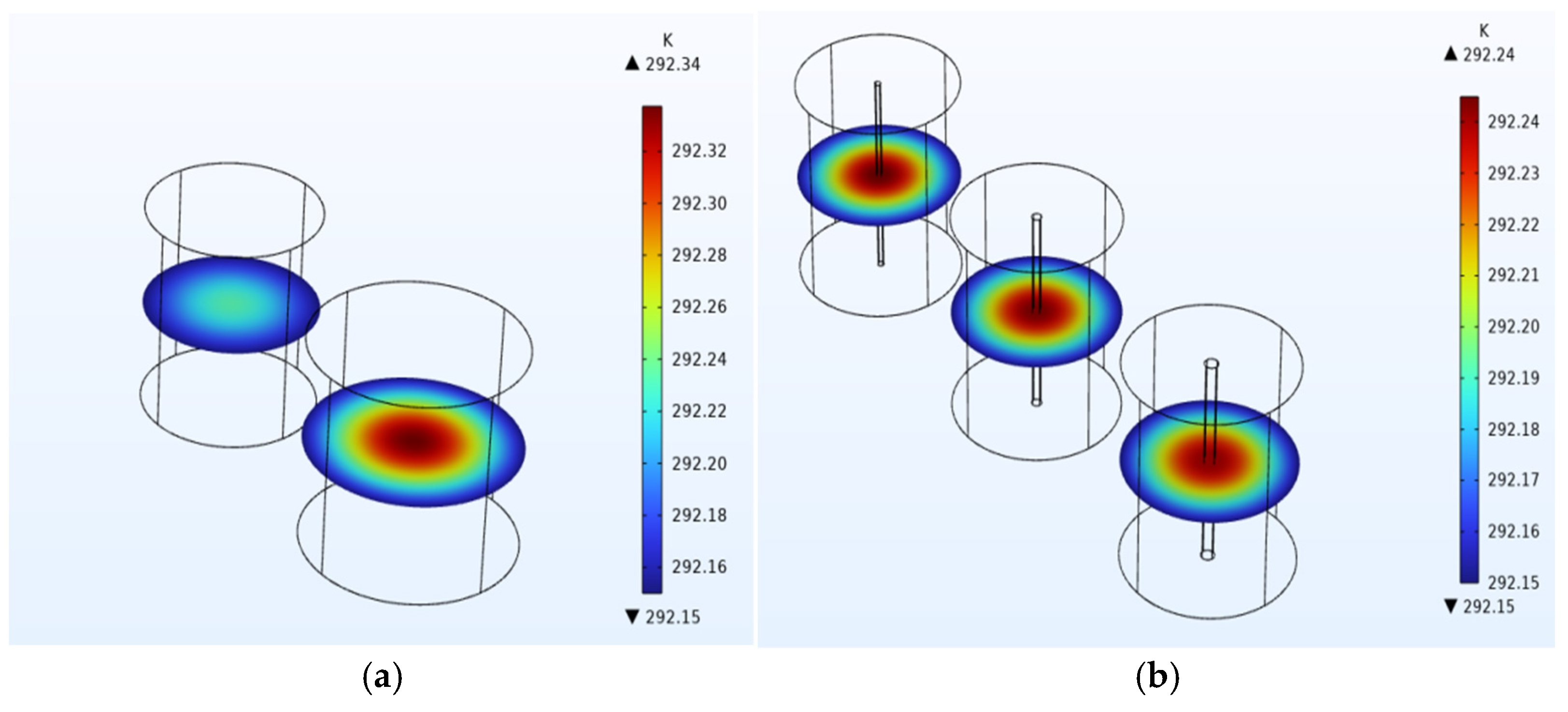
3.1. Simulation Analysis of the Temperature Sensing Structure

To improve the temperature response speed and sensitivity of the temperature-sensing FBG (FBG3), a metal with a high-thermal-conductivity and high-thermal-expansion coefficient is required. Table 1 shows the thermal conductivities and thermal expansion coefficients of several common metals. In addition, under the condition that the ambient temperature is 1 K lower than the initial temperature, heat transfer analysis was performed on five materials using tubes with a radius of 3.5 mm and a height of 5 mm, and the results are shown in Figure 3.
According to Table 1, although lead exhibits a relatively high linear expansion coefficient, its thermal conductivity is low. In contrast, silver shows both high thermal conductivity and a high thermal expansion coefficient. Moreover, as shown in Figure 3, under the condition where the external temperature is 1 K lower than the initial temperature, at the same moment the temperature change in the silver tube is much larger than that in metallic tubes made of other materials. This indicates that the silver tube experiences a faster temperature change and thus possesses excellent thermal conductivity. In summary, silver is selected as the encapsulation material. However, because silver is relatively soft—which may cause chirp in the FBG3 during actual measurements—modified epoxy adhesive DG-4 is used to bond FBG3 within the silver tube [39], thereby preventing chirp due to the soft nature of the silver tube. The temperature sensitivity is mainly contributed by the thermal expansion of the silver tube; however, considering that FBG3 is bonded on its exterior with modified epoxy adhesive DG-4, thermal analysis must account for the temperature variations in both the silver tube and the adhesive. The most critical factor influencing their thermal response is their thickness. Consequently, COMSOL Multiphysics v6.2 is employed to analyze the effects of the silver tube’s thickness and that of the modified epoxy adhesive DG-4.
Silver tubes with radii of 2.5 mm and 3 mm were modeled, and finite element as well as temperature response analyses were conducted. With an initial temperature set at 293.15 K, equilibrium is generally assumed when the initial temperature difference between the internal and external layers will drop by 90%. Given an external temperature of 292.15 K, equilibrium is achieved when the internal temperature reaches 292.25 K. Under the condition of the external temperature being 1 K lower than the initial temperature, the cross-sectional temperature distributions of the two silver tubes at 22 ms are shown in Figure 4a. The maximum internal temperature in the 3 mm radius silver tube is 292.34 K, indicating that it has not yet reached equilibrium, whereas the 2.5 mm radius silver tube has already reached equilibrium. Considering that the silver tube also functions to protect the fiber Bragg grating, its thickness must not be too small; hence, a silver tube with a 2.5 mm radius is selected for encapsulating the fiber Bragg grating. For the selection of the modified epoxy adhesive DG-4 thickness, models with adhesive thicknesses of 0.1 mm, 0.15 mm, and 0.2 mm were developed and subjected to finite element and temperature response analyses. Under the same initial condition of 293.15 K with an external temperature of 292.15 K, the temperature distribution cross-sections for the three adhesive thicknesses at 22 ms are shown in Figure 4b. Based on the equilibrium criterion, all three adhesive layers have reached equilibrium, and the maximum internal temperature differences among them are minimal. Notably, the adhesive with a thickness of 0.2 mm exhibits a slightly lower maximum temperature than the other two thicknesses. Therefore, a 0.2 mm-thick modified epoxy adhesive DG-4 is chosen.
Consequently, the final design employs a silver tube with a radius of 2.5 mm and a 0.2 mm-thick modified epoxy adhesive DG-4 to encapsulate and bond FBG3. Next, the temperature sensitivity and response time of this structure are further analyzed.
The silver tube has a thermal expansion coefficient of α 1 = 19.5 × 10⁻⁶/°C, the epoxy adhesive has a thermal expansion coefficient of α 2 = 56.8 × 10⁻⁶/°C, and FBG3 has a linear expansion coefficient of α = 0.55 × 10⁻⁶/°C and a thermo-optic coefficient of 6.67 × 10⁻⁶/°C. Substituting these values into Equation (3) yields a temperature sensitivity K T = 102.77 pm/°C for FBG3, with a central wavelength of 1550 nm. In the transient solid-state heat transfer analysis of FBG3, as observed from Figure 4, the structure reaches thermal equilibrium within 22 ms. Therefore, with a time step of 2 ms, the temperature change within the structure from 0 to 22 ms was recorded, as shown in Figure 5. It can be seen from Figure 5 that when the temperature decreases from 293.15 K to 292.15 K, the structure reaches equilibrium at 17.4 ms, indicating a temperature response time of 17.4 ms.

3.2. Simulation Analysis of the Pressure-Sensing Structure

In this sensor design, depth detection is achieved by the deformation of the pressure-sensing fiber Bragg grating (FBG2) induced by external pressure. The selection of different FBG2 lengths directly affects the sensor’s dimensions and response time; thus, the optimal FBG dimensions must be discussed. FBGs with effective lengths of 5 mm, 7 mm, 10 mm, and 12 mm (with a diameter of 125 μm) were compared under a pressure of 1 MPa. Their response times ranged from 0 ms to 1 ms (with a step of 0.1 ms). Figure 6 shows the relationship between the deformation Δx and time t at 1 ms for these four different effective lengths of FBG2.
When a 1 MPa pressure step is transmitted to FBG2 in a very short time, a pressure wave enters the grating at its front end and travels toward the back. Before the wave has fully passed through the entire grating, only the front half of the grating is compressed, so the measured compression rises rapidly; once the wave reaches the far end, the strain reaches its maximum. Thereafter, internal stresses within the grating and its packaging redistribute, with local strains counteracting each other, causing the compression to fall from the peak, oscillate slightly, and finally settle at the same value as under static loading. As seen in Figure 6, under the same pressure the deformation of the FBG is related to its length; the longer the FBG, the greater the deformation. However, longer FBGs require more time to reach strain equilibrium. In this case, all four FBGs reach equilibrium within 1 ms, indicating a very fast strain response. Based on the deformation results, an FBG that exhibits a larger deformation under the same pressure is preferable. Nevertheless, due to sensor size constraints (the gap between the lower end of the 304 stainless-steel tube housing the temperature compensation FBG1 and the protrusion of the 304 stainless-steel casing is 14 mm, with a 2 mm gap at each end for FBG2 movement), a 10 mm effective length FBG is selected as the optimal choice. Based on the existing literature and actual product parameters [40], common expendable temperature–depth sensors typically exhibit a “time lag” effect. In other words, it takes approximately 25–30 s from the moment of immersion until the sensor’s temperature reading fully equilibrates with the seawater temperature and reaches a stable state. Once stabilized, the data are transmitted in real time to the vessel via optical cable. Due to the extremely high propagation speed of signals in the cable—where the group velocity in a single-mode fiber is approximately 2.04 × 10⁸ m/s—the signal transmission time over a distance of 1000 m is only about 5 μs.
The designed ocean temperature and depth sensor is intended for applications in ocean depths of 0–1000 m, corresponding to an operating pressure range of 0–10 MPa (in oceanic scenarios, 1 MPa is approximately equivalent to 100 m underwater). The sensor’s pressure sensitivity primarily relies on two key components: the 7075 aluminum alloy piston and the polymer encapsulation material. The piston converts external pressure into mechanical displacement, while the polymer encapsulation material, through its elasticity, effectively transmits the strain induced by pressure to FBG2, thereby altering its central wavelength. Therefore, in-depth analysis and optimization of these two materials are critical for achieving high sensitivity and fast response in depth detection.
FBG2 is encapsulated with a polymer material. To enhance the sensitization effect of the encapsulation structure, the influence of various polymer parameters on the pressure sensitivity of the fiber Bragg grating must be examined to achieve an optimized design. When the Young’s modulus [41] and Poisson’s ratio [42] of the polymer encapsulation material are low, the pressure sensitivity of the fiber Bragg grating is higher. However, because Poisson’s ratio and Young’s modulus are interdependent, several commonly used polymers were selected as candidate materials for FBG encapsulation, with their relevant parameters presented in Table 2. Under a pressure range of 0–10 MPa, four materials were compared; the results are shown in Figure 7.
From Table 2, it is evident that polycarbonate has both a relatively low Poisson’s ratio and a low Young’s modulus. Figure 7 further shows that, with increasing pressure, the strain produced in all four polymer materials increases linearly, with polycarbonate exhibiting significantly higher strain compared to polyethylene, polyimide, and epoxy resin. Although theoretically pressure sensitivity is proportional to the ratio of Poisson’s ratio to Young’s modulus—meaning polymers with a higher Poisson’s ratio can produce greater axial strain—considering Poisson’s ratio alone is insufficient; Young’s modulus must also be taken into account. Although polycarbonate’s Poisson’s ratio is lower than that of many soft encapsulation polymers, its relatively high Young’s modulus prevents collapse under deep-sea pressures and provides excellent mechanical and chemical stability. As a result, polycarbonate can still effectively convert radial compression into axial strain—enhancing FBG sensitivity—while maintaining long-term structural integrity and manufacturing consistency. Thus, polycarbonate is chosen as the encapsulation material for the FBG.
To further optimize the encapsulation design—ensuring that the polymer both protects the FBG and provides the best strain response under pressure—the thickness of the polycarbonate is analyzed. Considering the overall dimensions of the sensor, finite element analysis was performed using COMSOL on a polycarbonate encapsulation with a length of 15 mm (for a 10 mm-high fiber Bragg grating) and a thicknesses ranging from 2.0 mm to 5.4 mm in 0.2 mm increments. The resulting radial deformation is shown in Figure 8. Under a pressure of 10 MPa, the differences in deformation for thicknesses between 2.0 mm and 5.4 mm are minor; however, polycarbonate layers between 3 mm and 4 mm exhibit slightly larger deformations. Since both 3 mm and 4 mm thicknesses yield a deformation of 40.1 μm, and considering that the encapsulation material must provide sufficient mechanical protection for the FBG without being excessively thick (which would compromise the sensor’s sensitivity), a thickness of 3.5 mm—being the midpoint between 3 mm and 4 mm—is selected. Compared to 4 mm, a 3.5 mm thickness is less likely to diminish sensitivity while offering better structural support and resistance to deformation than 3 mm. Additionally, a 3.5 mm thickness is easier to control in manufacturing, ensuring consistency and repeatability in the encapsulation. Therefore, a polycarbonate thickness of 3.5 mm is chosen for FBG encapsulation.
The piston, as the mechanical transducer of the sensor, converts externally applied pressure into displacement. The rigidity, density, and friction properties of the piston material directly determine whether a larger overall displacement can be achieved under the same pressure, thereby influencing the system’s response speed and sensitivity. Several commonly used materials were considered for the piston, with their properties listed in Table 3. Under a pressure range of 0–10 MPa four materials were compared, and the results are shown in Figure 9.
According to Table 3, aluminum alloy has both a low density and a low Young’s modulus, while also exhibiting good strength and rigidity. Figure 9 shows that under increasing pressure, the strain in all four materials increases, with the deformation of aluminum alloy being significantly greater than that of the other three materials under the same pressure. Consequently, aluminum alloy is chosen as the piston material. After discussing the selection of materials for both the polymer encapsulation and the piston, the main parameters of the proposed sensor structure are summarized in Table 4. In this design, the 304 stainless-steel tube is welded to the lower end of the piston to prevent the internal temperature compensation FBG from being affected by seawater temperature. The stainless-steel tube is free to move with the piston displacement. Since it does not contribute to pressure-sensing enhancement, its material selection is not further discussed here.
Finite element analysis was performed on the structure with the chosen dimensions, as shown in Figure 10b,c. When a boundary load of 10 MPa is applied to the piston, it moves downward, and under its influence the displacement deformation on the polymer surface is 70.4 μm. This displacement is greater than that obtained when the polymer is subjected solely to a 10 MPa pressure (applied directly at its boundary), proving that the piston can enhance sensitivity. The simulation results confirm that both the piston and the polymer contribute to the enhanced sensitivity of the structure, as evidenced by the polymer deformation shown in Figure 10a,b.
When the effective length of FBG2 is 10 mm and its central wavelength is set at 1310 nm, the sensor’s pressure sensitivity can be calculated as 1.26 nm/MPa. A deformation and response time analysis of the structure was conducted under a 1 MPa load over a 40 ms period, using a time step of 1 ms, as shown in Figure 11.
According to Figure 11, the deformation of the pressure-sensing structure exhibits an oscillatory trend before gradually stabilizing, reaching equilibrium at 31 ms. Therefore, the depth sensing response time of the sensor is 31 ms. With the temperature sensing response time being 17.4 ms, the difference is 13.6 ms—too large to achieve synchronized temperature and pressure response times. To reduce the pressure response time and better match it with the temperature response, the length and thickness of the polycarbonate should be adjusted. As shown in Figure 8, polycarbonate layers with thicknesses between 3 mm and 4 mm exhibit slightly larger deformations than those of other thicknesses. Consequently, simulations were carried out on polycarbonate layers with lengths of 8 mm, 10 mm, and 15 mm and thicknesses in the 3–4 mm range (using a step of 0.1 mm): the resulting response times are presented in Figure 12.
Figure 12 indicates that as the thickness increases, the response time first decreases and then increases. Specifically, an 8 mm long polycarbonate achieves its minimum response time of 19 ms at a thickness of 3.6 mm; a 10 mm long polycarbonate reaches a minimum response time of 24 ms at 3.7 mm thickness; and a 15 mm long polycarbonate has a minimum response time of 31 ms at 3.5 mm thickness. It is evident that the pressure response time of the 8 mm polycarbonate is lower than those of the 10 mm and 15 mm variants. Thus, by using a polycarbonate with the dimensions of 8 mm in length and 3.6 mm in thickness to encapsulate the FBG, the sensor’s pressure sensitivity can be recalculated as 1.33 nm/MPa. Under a 1 MPa load and over a 40 ms period (with a 1 ms time step), the relationship between deformation and response time was analyzed, as shown in Figure 13. The blue dots in Figure 13 indicate that the deformation of the pressure-sensing structure oscillates before stabilizing by 19 ms, yielding a pressure response time of 19 ms with the MOI-S155 interrogator operating in standard 1 kHz. This is only 1.6 ms different from the temperature response time (17.4 ms). Compared with the pre-optimization deformation (indicated by the red dots), the optimized sensor not only shows a significantly reduced response time but also a slight increase in deformation—suggesting an improvement in pressure sensitivity. In comparison with the temperature and depth sensor based on a diaphragm and liquid filling which is reported in, the present structure not only improves response speed by more than twofold but also synchronizes the acquisition speeds of temperature and depth measurements, whilst extending the pressure detection range to 1000 m. Compared with the ship-borne, expendable, all-fiber optic ocean temperature–depth profile sensor described in [24], the temperature sensitivity of the proposed structure is enhanced by nearly 10 times. Although the sensor in [24] achieves a pressure sensitivity of 3 nm/MPa, its detection depth is limited to 0–60 m. In contrast, the sensor presented here attains a pressure sensitivity of 1.33 nm/MPa while enabling depth detection from 0 to 1000 m.

3.3. Experimental Validation

In the temperature calibration experiment, the fabricated sensor was immersed in a thermostatic water bath maintained at an initial temperature of 30 °C for approximately 30 min. The bath’s temperature stability was better than ±0.05 °C, monitored continuously by a calibrated four-wire PT100 platinum-resistance thermometer (JUMO GmbH, Fulda, Germany, uncertainty ±0.02 °C). Data acquisition was performed using an MOI-SI155 fiber Bragg grating interrogator (Luna Innovations, Atlanta, GA, USA) connected to the sensor’s tail fiber. This instrument provides a wavelength resolution and accuracy of 1 pm. Acquisition commenced only after the bath temperature had stabilized within ±0.05 °C of the setpoint for at least 5 min. This ensured that the internal temperature gradient of the silver tube-encapsulated FBG3 was below 0.1 °C. The interrogator recorded both the wavelength shift in the temperature-sensing FBG3 and the water-bath thermometer reading. Subsequently, the water bath’s operating temperature was decreased in 5 °C increments down to 0 °C. After each decrement, once the temperature in the vicinity of the sensor stabilized, the wavelength of FBG3 and the corresponding thermometer reading were recorded again. Once the cooling process was completed, the water bath temperature was then increased from 0 °C back to 30 °C in 5 °C increments, during which the same interrogator was used to record FBG3’s wavelength and the temperature readings. The data obtained from the temperature calibration experiment were consolidated, and a linear regression was performed to derive the relationship between the sensor’s wavelength and temperature, as shown in Figure 14a. Here, R2—the coefficient of determination—indicates the degree to which the data points cluster around the fitted line, with values ranging from 0 to 1 (a higher R2 denotes a better fit). The R2 value for the heating curve was 99.905% and 99.919% for the cooling curve, demonstrating an excellent fit of the model. The average temperature sensitivity of the temperature–depth sensor was determined to be 109.9 pm/°C, slightly higher than the simulated result of 102.77 pm/°C. Upon analysis, this increase in sensitivity is attributed to the curing process of the epoxy adhesive DG-4 used to bond the temperature-sensing FBG to the silver tube. During curing, the epoxy adhesive undergoes an initial exothermic reaction that causes a slight volumetric expansion due to the temperature rise, but as the cure progresses it ultimately shrinks, exerting a compressive force on the fiber and effectively shortening its length, thereby enhancing the temperature sensitivity.
In the pressure calibration experiment, the temperature–depth sensor was sealed inside a piston-type pressure gauge using a rotary connector. An MOI-SI155 fiber Bragg grating interrogator, connected to the sensor’s tail fiber, was used to record in real time the wavelength of the pressure-sensing FBG2 under different pressure conditions. The sensor’s designed pressure range is 10 MPa. Pressure testing commenced from 0 MPa to 10 MPa, with 1 MPa increments, and then decreased from 10 MPa back to 0 MPa in 1 MPa decrements. Through multiple repeated measurements and optimized calibration procedures, the expanded uncertainty was ultimately controlled within ±0.01 MPa, ensuring high accuracy and repeatability across the full 0–10 MPa range. After consolidating the data obtained from the pressure calibration experiment, a linear regression was performed to determine the relationship between the sensor’s wavelength and pressure, as shown in Figure 14b. The pressure ramp-up curve exhibited an R2 of 99.954%, and an R2 of 99.928% for the ramp-down curve, indicating an excellent model fit. The average pressure sensitivity of the temperature–depth sensor was determined to be 1.63 nm/MPa, higher than the simulated value of 1.33 nm/MPa. This increase in sensitivity is likely due to the epoxy adhesive shortening the effective length of the pressure-sensing FBG2 during curing.
In the temperature experiments, the silver tube and its packaging structure possess a degree of thermal inertia, resulting in a delayed response to temperature changes. During cooling, although heat is rapidly conducted through the outer silver tube, residual heat remains internally and must be gradually dissipated, causing a slight lag in the sensor’s temperature response compared to heating. In the pressure experiments, the piston-type pressure chamber may exhibit frictional resistance during both pressurization and depressurization, causing the pressure decrease during unloading to lag behind the theoretical value; meanwhile, the polymer-encapsulated material undergoes elastic deformation under applied pressure but does not immediately fully recover upon unloading, giving rise to a small hysteresis in the pressure response.

4. Conclusions

This paper presents the design of an ocean temperature and depth sensor based on cascaded FBGs with a temperature compensation structure. For the pressure-sensing component, a secondary sensitization mechanism is implemented by transmitting strain via a piston to an FBG encapsulated in a polycarbonate buffer. For the temperature-sensing component, an FBG is encapsulated within a metallic silver tube and coated with a modified epoxy adhesive DG-4 to prevent chirp caused by the softness of the silver tube. A dedicated FBG-based temperature compensation structure is also incorporated to eliminate temperature-induced errors in the pressure-sensing FBG, thereby enhancing its pressure sensitivity. By adjusting the materials and dimensions of the piston, metallic tube, polymer, and adhesive, the sensor’s sensitivity and response speed can be finely tuned. Simulation results indicate that strain transfer through a piston made of 7075 aluminum alloy, the encapsulation of FBG2 in a polycarbonate buffer, and the encapsulation of FBG3 in a metallic silver tube yield effective sensitization. In particular, a metallic silver tube with a radius of 2.5 mm and a modified epoxy adhesive DG-4 layer with a thickness corresponding to a radius of 0.2 mm exhibit superior thermal conduction characteristics. Under the combined influence of the piston, polymer, and metallic tube, the optimized FBG sensor demonstrates significantly enhanced sensitivity, achieving a pressure sensitivity of 1.33 nm/MPa and a temperature sensitivity of 102.77 pm/°C. The experimental results show that the temperature sensitivity is 109.9 pm/°C within the temperature range of 0~30 °C and the pressure sensitivity is 1.63 nm/MPa within the pressure range of 1~10 MPa. This ocean temperature and depth sensor can meet the high-precision detection requirements for ocean depths ranging from 0 to 1000 m. In future work, we will complete the fabrication, encapsulation, system integration, and experimental validation of the sensor, with ongoing efforts to further optimize its detection performance.

Author Contributions

Conceptualization, X.Z. and L.L. (Lin Li); methodology, L.Z. and Z.L. (Zaijin Li); data curation, C.W., S.L. and S.L.; writing—original draft preparation, X.Z., L.Z., C.W., G.L. and L.L. (Lu Li); writing—review and editing, Y.L., Z.L. (Zichun Le) and L.Z.; visualization, G.L., H.C. and Y.Q.; supervision, L.L. (Lianhe Li) and Y.Q.; funding acquisition, L.Z., Y.Q. and L.L. (Lin Li). All authors have read and agreed to the published version of the manuscript.

Funding

This research was funded by the Finance Science and Technology Project of Hainan province, grant numbers GHYF2025030 and ZDYF2025GXJS007, the Hainan Provincial Natural Science Foundation of China, grant number 123MS035, the National Natural Science Foundation of China, grant numbers 62174046, 12164016, 62274048 and 62464006, the Funding for physics discipline construction of Hainan Normal University (2025), and the Open Fund for Innovation Training Program of College Students of Hainan Normal University (S202411658030).

Institutional Review Board Statement

Not applicable.

Informed Consent Statement

Not applicable.

Data Availability Statement

Data are contained within the article.

Conflicts of Interest

The authors declare no conflicts of interest.

References

  1. Wang, X.; Wang, J.; Wang, S.S.; Liao, Y.P. Fiber-optic salinity sensing with a panda-microfiber-based multimode interferometer. J. Light. Technol. 2017, 35, 5086–5091. [Google Scholar] [CrossRef]
  2. Zhao, X.; Wei, C.; Zeng, L.; Sun, L.; Li, Z.; Chen, H.; Liu, G.; Qiao, Z.; Qu, Y.; Xu, D.; et al. Research Progress in Fiber Bragg Grating-Based Ocean Temperature and Depth Sensors. Sensors 2024, 25, 183. [Google Scholar] [CrossRef]
  3. Xu, Y.; Chen, Y.; Cui, C.; Lv, W.; Liu, X. High-sensitivity ocean temperature sensor using a reflective optical microfiber coupler and machine learning methods. Appl. Opt. 2024, 63, 8771–8779. [Google Scholar] [CrossRef] [PubMed]
  4. Goes, M.; Goni, G.; Dong, S.; Boyer, T.; Baringer, M. The Complementary Value of XBT and Argo Observations to Monitor Ocean Boundary Currents and Meridional Heat and Volume Transports: A Case Study in the Atlantic Ocean. J. Atmos. Ocean. Technol. 2020, 37, 2267–2282. [Google Scholar] [CrossRef]
  5. Yan, Y.; Gu, Z.; Wang, Y.; Du, J. Design and simulation of reflective fiber grating sensor for simultaneous monitoring of CTD in marine environment. J. Opt. 2024, 1–12. [Google Scholar] [CrossRef]
  6. Goes, M.; Goni, G.; Dong, S. An optimal XBT-based monitoring system for the South Atlantic meridional overturning circulation at 34° S. J. Geophys. Res. Oceans 2015, 120, 161–181. [Google Scholar] [CrossRef]
  7. Liu, Z.; Zhang, Y.; Zeng, L.; Li, Z.; Chen, H.; Qiao, Z.; Qu, Y.; Liu, G.; Li, L. Structural Design of Ocean Temperature and Depth Sensor with Quick Response and High Sensitivity. Sensors 2022, 22, 7756. [Google Scholar] [CrossRef]
  8. Liu, Z.; Zeng, L.; Xu, K.; Li, Z.; Chen, H.; Qiao, Z.; Qu, Y.; Liu, G.; Li, L. Design of a Fiber Bragg Grating Pressure Sensor Based on a Metal Diaphragm and Lever Structure. Sensors 2022, 22, 5096. [Google Scholar] [CrossRef]
  9. Meng, Q.; Wang, J.; Chen, D.; Chen, J.; Xie, B.; Lu, Y. An Ultra-low Thermal Sensitivity Drift Piezoresistive Pressure Sensor Compensated by Passive Resistor/Thermistor Network. J. Phys. Conf. Ser. 2024, 2740, 012042. [Google Scholar] [CrossRef]
  10. Tagawa, M.; Kato, K.; Ohta, Y. Response Compensation of Thermistors: Frequency Response and Identification of Thermal Time Constant. Rev. Sci. Instrum. 2003, 74 Pt 1, 1350–1358. [Google Scholar] [CrossRef]
  11. Su, F.; Hu, Y.; Zhu, X.; Lai, T. Enhancing the Thermal Stability and Reducing the Resistance Drift of Sb Phase Change Films by Adding In2Se3 Interlayers. Coatings 2023, 13, 927. [Google Scholar] [CrossRef]
  12. Cui, C.; Gao, L.; Dai, N.; Xu, Q. Fiber Bragg Grating Inclinometer-enabled IoT Sensing System with Low Power Consumption and Small Size. Sens. Mater. 2021, 33, 2321–2331. [Google Scholar] [CrossRef]
  13. Xu, B.; Chen, G.; Xu, X.; Liu, S.; Liao, C.; Weng, X.; Liu, L.; Qu, J.; Wang, Y.; He, J. Highly birefringent side-hole fiber Bragg grating for high-temperature pressure sensing. Opt. Lett. 2024, 49, 1233–1236. [Google Scholar] [CrossRef]
  14. Zhang, S.; Liu, X.; Wang, Z.; Liu, Y. Single Mode Fiber Dislocation Mach–Zehnder Interferometer Cascaded with Fiber Bragg Grating for Monitoring Metal Electrochemical Corrosion. Optoelectron. Lett. 2023, 19, 653–658. [Google Scholar] [CrossRef]
  15. Kumar, J.; Prakash, O.; Agrawal, S.K.; Mahakud, R.; Mokhariwale, A.; Dixit, S.K.; Nakhe, S.V. Distributed fiber Bragg grating sensor for multipoint temperature monitoring up to 500 °C in high-electromagnetic interference environment. Opt. Eng. 2016, 55, 090502. [Google Scholar] [CrossRef]
  16. Hnatovsky, C.; Silva, K.D.; Abdukerim, N.; Walker, R.B.; Ding, H.; Mihailov, S.J. Nanoscale Morphology and Thermal Properties of Low Insertion Loss Fiber Bragg Gratings Produced Using the Phase Mask Technique and a Single Femtosecond Laser Pulse. Opt. Express 2022, 30, 47361–47374. [Google Scholar] [CrossRef]
  17. Purwasih, N.; Shinozaki, H.; Okazaki, S.; Kihira, H.; Kuriyama, Y.; Kasai, N. Atmospheric Corrosion Sensor Based on Strain Measurement with Active–Dummy Fiber Bragg Grating Sensors. Metals 2020, 10, 1076. [Google Scholar] [CrossRef]
  18. Kanakambaran, S.; Sarathi, R.; Srinivasan, B. Identification and localization of partial discharge in transformer insulation adopting cross recurrence plot analysis of acoustic signals detected using fiber Bragg gratings. IEEE Trans. Dielectr. Electr. Insul. 2017, 24, 1773–1780. [Google Scholar] [CrossRef]
  19. Yan, G.; Wang, T.; Zhu, L.; Meng, F.; Zhuang, W. A Novel Strain-Decoupled Sensitized FBG Temperature Sensor and Its Applications to Aircraft Thermal Management. Opt. Laser Technol. 2021, 140, 106597. [Google Scholar] [CrossRef]
  20. Hong, L.; Wang, J.; Cai, J.; Teng, Y.; Qiu, Z. Substrate-Type Sensitized FBG Temperature Sensor. Sens. Rev. 2023, 43, 83–91. [Google Scholar] [CrossRef]
  21. Gu, Y.; Zhao, Y.; Lv, R.Q.; Zhang, W.; Yang, B. A Practical FBG Sensor Based on a Thin-Walled Cylinder for Hydraulic Pressure Measurement. IEEE Photonics Technol. Lett. 2016, 28, 2569–2572. [Google Scholar] [CrossRef]
  22. Hegde, G.; Prasad, M.V.N.; Asokan, S. Temperature compensated diaphragm based Fiber Bragg Grating (FBG) sensor for high pressure measurement for space applications. Microelectron. Eng. 2021, 248, 111615. [Google Scholar] [CrossRef]
  23. Fadeev, K.M.; Larionov, D.D.; Zhikina, L.A.; Minkin, A.M.; Shevtsov, D.I. A Fiber-Optic Sensor for Simultaneous Temperature and Pressure Measurements Based on a Fabry–Perot Interferometer and a Fiber Bragg Grating. Instrum. Exp. Tech. 2020, 63, 543–546. [Google Scholar] [CrossRef]
  24. Zhao, Q.; Wang, Y.; Sun, P.; Du, D.; Yu, L.; Zhang, J.; Ding, B.; Han, G.; Qu, Y. Shipborne expendable all-optical fiber ocean temperature-depth profile sensor. Appl. Opt. 2022, 61, 2089–2095. [Google Scholar] [CrossRef]
  25. Hopf, B.; Fischer, B.; Bosselmann, T.; Koch, A.W.; Roths, J. Strain-Independent Temperature Measurements with Surface-Glued Polarization-Maintaining Fiber Bragg Grating Sensor Elements. Sensors 2019, 19, 144. [Google Scholar] [CrossRef]
  26. Kuang, Y.; Guo, Y.; Xiong, L.; Liu, W. Packaging and Temperature Compensation of Fiber Bragg Grating for Strain Sensing: A Survey. Photonic Sens. 2018, 8, 320–331. [Google Scholar] [CrossRef]
  27. Fajkus, M.; Nedoma, J.; Martinek, R.; Fridrich, M.; Bednar, E.; Zabka, S.; Zmij, P. Pressure Membrane FBG Sensor Realized by 3D Technology. Sensors 2021, 21, 5158. [Google Scholar] [CrossRef]
  28. Dzipalski, A.; Morton, J.A.S.; Papachristou, N.; Maier, R.R.J.; MacPherson, W.N.; Ristolainen, A.; Reilent, E.; Kruusmaa, M.; Wolf, B.J.; Pirih, P.; et al. A Multiplexed Reconfigurable Modular FBG Based Sensor Platform for Flow and Temperature Measurements in the North Sea. In Remote Sensing for Agriculture, Ecosystems, and Hydrology XXVI; Neale, C.M.U., Maltese, A., Bostater, C.R., Nichol, C., Eds.; SPIE: Bellingham, WA, USA, 2024; Volume 13191, p. 1319104. [Google Scholar] [CrossRef]
  29. Shang, Q.; Qin, W. Fiber Bragg Grating Dynamic Calibration Based on Online Sequential Extreme Learning Machine. Sensors 2020, 20, 1840. [Google Scholar] [CrossRef]
  30. Brown, R.T.; MacPherson, W.N.; Maier, R.R.J.; Barton, J.S.; Jones, J.D.C.; Collins, A.T. An Optical Fibre Depth (Pressure) Sensor for Remote Operated Vehicles in Underwater Applications. Sensors 2017, 17, 406. [Google Scholar] [CrossRef] [PubMed]
  31. Liu, Y.; Fang, J.; Zhang, X.; Chen, R.; Xu, Y. Submarine Optical Fiber Sensing System for the Real-Time Monitoring of Depth, Vibration, and Temperature. Front. Mar. Sci. 2022, 9, 870674. [Google Scholar] [CrossRef]
  32. Pei, W.; Pei, X.; Xie, Z.; Wang, J. Research progress of marine anti-corrosion and wear-resistant coating. Tribol. Int. 2024, 198, 109864. [Google Scholar] [CrossRef]
  33. Zhan, W.; Li, X.; Qian, X.; Li, Y.; Ding, Y.; Zu, Y.; Xie, F.; Tian, F. Preparation and Characterization of Synchronous Chemical Conversion Coating on 6061 Aluminum Alloy/7075 Aluminum Alloy/Galvanized Steel Substrates. Metals 2022, 12, 2011. [Google Scholar] [CrossRef]
  34. Udd, E.; Spillman, W.B. Fiber Optic Sensors: An Introduction for Engineers and Scientists, 2nd ed.; Wiley: Hoboken, NJ, USA, 2011. [Google Scholar]
  35. Zhang, H.; Xue, X. The research progress on corrosion and protection of silver layer. SN Appl. Sci. 2019, 1, 464. [Google Scholar] [CrossRef]
  36. Raju, B.; Kumar, R.; Dhanalakshmi, S.; Hrbac, R.; Demel, L.; Narayanamoorthi, R. Experimental investigation on polymer coated fibre bragg grating sensor for temperature measurement in sewer environment. Results Eng. 2025, 25, 104319. [Google Scholar] [CrossRef]
  37. Bakaic, M.; Hanna, M.; Hnatovsky, C.; Grobnic, D.; Mihailov, S.; Zeisler, S.S.; Hoehr, C. Fiber-Optic Bragg Gratings for Temperature and Pressure Measurements in Isotope Production Targets for Nuclear Medicine. Appl. Sci. 2020, 10, 4610. [Google Scholar] [CrossRef]
  38. Wang, H.-P.; Dai, J.-G.; Wang, X.-Z. Improved Temperature Compensation of Fiber Bragg Grating-Based Sensors Applied to Structures under Different Loading Conditions. Opt. Fiber Technol. 2021, 63, 102506. [Google Scholar] [CrossRef]
  39. Yu, X.; Shuai, C.; Yang, X.; Lu, G.; Liang, C.; Liu, Z. Design and testing of a smart rubber stave for marine water-lubricated bearings. Sci. Eng. Compos. Mater. 2022, 29, 215–226. [Google Scholar] [CrossRef]
  40. Cheng, L.; Zhu, J.; Cowley, R.; Boyer, T.; Wijffels, S. Time, Probe Type, and Temperature Variable Bias Corrections to Historical Expendable Bathythermograph Observations. J. Atmos. Ocean. Technol. 2014, 31, 1793–1825. [Google Scholar] [CrossRef]
  41. Abeywardena, C.L.; Zhang, Q.; Korposh, S.; Morgan, S.P.; Bull, S.; Correia, R. Highly Sensitive Optical Fibre Bragg Grating Contact Pressure Sensor Embedded in a Polymer Layer: Modelling and Experimental Validation. Results Opt. 2024, 14, 100604. [Google Scholar] [CrossRef]
  42. Moccia, M.; Pisco, M.; Cutolo, A.; Galdi, V.; Bevilacqua, P.; Cusano, A. Opto-acoustic behavior of coated fiber Bragg gratings. Opt. Express 2011, 19, 18842–18860. [Google Scholar] [CrossRef] [PubMed]
Figure 1. Schematic diagram of the ocean temperature and depth sensor based on FBGs.
Coatings 15 00795 g001
Figure 2. Cross-sectional view of the fiber Bragg gratings. (a) Pressure-sensing fiber Bragg grating (FBG2). (b) Temperature-sensing fiber Bragg grating (FBG3).
Coatings 15 00795 g002
Figure 3. Heat transfer performance of metal tubes made of the five materials.
Coatings 15 00795 g003
Figure 4. Cross-sectional temperature distribution from simulation at 22 ms. (a) Metal silver tube thicknesses: 2.5 mm and 3 mm. (b) Adhesive thicknesses: 0.1 mm, 0.15 mm, and 0.2 mm.
Coatings 15 00795 g004
Figure 5. Graph showing the relationship between temperature change and response time.
Coatings 15 00795 g005
Figure 6. Time–response curves of deformation for FBG2 with four different lengths under 1 MPa pressure.
Coatings 15 00795 g006
Figure 7. Deformation versus pressure curves for four polymer materials.
Coatings 15 00795 g007
Figure 8. Radial deformation distribution for polycarbonate layers of various thicknesses under 10 MPa.
Coatings 15 00795 g008
Figure 9. Deformation versus pressure curves for four piston materials.
Coatings 15 00795 g009
Figure 10. Comparison of deformation components before and after piston sensitization. (a) Polymer deformation distribution before sensitization, (b) polymer deformation distribution after sensitization, (c) piston displacement under a 10 MPa pressure load.
Coatings 15 00795 g010
Figure 11. Relationship between deformation and response time.
Coatings 15 00795 g011
Figure 12. Relationship between the response time of polycarbonate and its thickness and length.
Coatings 15 00795 g012
Figure 13. Relationship between deformation and response time compared with original and optimized data.
Coatings 15 00795 g013
Figure 14. Calibration curves of temperature and pressure for the fiber Bragg grating-based oceanic temperature–depth sensor. (a) Temperature calibration curve; (b) pressure calibration curve.
Coatings 15 00795 g014
Table 1. Thermal conductivity and thermal expansion coefficients of metal materials.
MaterialsLinear Expansion CoefficientThermal ConductivitySource
Aluminum23.0 × 10−6 pm/°C237 W/mKGoodfellow Cambridge Ltd., Huntingdon, UK
Silver19.5 × 10−6 pm/°C429 W/mK
Copper17.5 × 10−6 pm/°C401 W/mK
Iron11.8 × 10−6 pm/°C80 W/mK
Lead29.0 × 10−6 pm/°C34.8 W/mK
Table 2. Poisson’s ratios and Young’s moduli of polymer materials.
MaterialsPoisson’s RatioYoung’s ModulusSource
Epoxy resin0.383 GPaEpoxy Technology, Billerica, MA, USA
Polycarbonate0.241.448 GPaCovestro AG, Leverkusen, Germany
Polyimide0.342.914 GPaDuPont, Wilmington, DE, USA
Polyethylene0.451.2 GPaLyondellBasell, Rotterdam, The Netherlands
Table 3. Densities and Young’s moduli of candidate piston materials.
MaterialsDensityYoung’s ModulusSource
Aluminum alloy2.7 g/cm375 GPaArconic, Pittsburgh, PA, USA
Steel7.9 g/cm3200 GPaOvako, Stockholm, Sweden
Titanium alloy4.5 g/cm3118 GPaTIMET, Warrensville Heights, OH, USA
Cast iron7.2 g/cm3123 GPaBradbury Group, Moundridge, KS, USA
Table 4. Main parameters of the pressure-sensing structure.
ComponentsPiston304 Stainless-Steel TubePolymer
MaterialsAluminum alloy304 Stainless-steelPolycarbonate
DimensionsLength = 15 mm, width = 8 mm, and
thickness = 6 mm
Length = 15 mm, width = 5 mm, and
thickness = 1 mm
Radius = 3.5 mm and length = 15 mm
Disclaimer/Publisher’s Note: The statements, opinions and data contained in all publications are solely those of the individual author(s) and contributor(s) and not of MDPI and/or the editor(s). MDPI and/or the editor(s) disclaim responsibility for any injury to people or property resulting from any ideas, methods, instructions or products referred to in the content.

