1. Introduction
Many parameters influence the structure of a single splat, and also, therefore, the thermal spray coating and its properties. The parameters are particle velocity; temperature; molten state; oxidation state; the substrate tilting angle; surface roughness; oxide layer composition and its thickness; and desorption of adsorbents and condensates. The physical properties of thermal conductivity and the wettability at impact between the thermal sprayed particle and the substrate influence the individual splat geometry [
1,
2] and the coating build-up and, consequently, the coating properties. The coating formation process is generally determined by the prime processing variables, which include substrate roughness, substrate temperature, impact velocity, stand-off distance (SOD), and the nature of the local atmospheric environment [
3,
4,
5,
6]. Many of these factors are inter-related. For example, SOD will influence the impact velocity as well as the substrate temperature due to heat transfer from the thermal spray torch.
The surface condition [
7,
8,
9,
10] and the wettability of the substrate play an important role in the morphology of splats [
11]. There are three factors affecting the wettability of the substrate. The first factor includes the substrate roughness, porosity and also the physical properties, such as thermal conductivity. Higher surface roughness enhances wettability of the substrate [
12], and higher thermal conductivity of the substrate, gives rise to poor wettability of the substrate [
13]. The second factor includes the composition, thickness and morphology of the oxide layer on the surface of the substrate; these are affected by the preheating rate, temperature and time. The thickness of the oxide layer affects the roughness of the substrate [
14], and thus modifies the wettability of the substrate [
1]. The third factor concerns condensates or adsorbents on the substrate surface. A higher content of condensates or adsorbates on the surface of the substrates, lower the wettability of the substrate; thus, more splash splats occur [
8,
9,
15].
Substrate wettability is one factor that influences the maximum diameter of a single splat. Other factors include the droplet initial diameter, impact velocity, surface tension and viscosity. The wettability of the substrate plays a significant role when the impact velocity becomes low. The higher the wettability of the substrate, then the larger the diameter of a single splat [
16], and the less likelihood of a splash splat [
17] feature.
The morphology of a single splat is related to the critical preheating temperature,
Tc, of the substrate [
18]. This temperature is also defined as the transition temperature (
Tt) of the substrate by Fukumoto [
19]. The splats are more disc-like when the substrate temperature is over
Tc. The splats are extensively fingered when the temperature is below
Tc. The value of
Tc is quite sensitive to the splat material rather than to the substrate [
18]. For alumina and zirconia,
Tc is around 200 to 250 °C [
20,
21] for disc splats deposited on low-carbon steel, stainless steel, aluminum alloys, zirconia, and alumina substrates. For EMAA,
Tc is around 90–100 °C [
22] for deposition onto mild steel.
Many spray process parameters correlate to each other. The splat spread factor decreases with an increase in substrate roughness [
23]. When the spray angle increases, splats exhibit an elliptical shape, and the aspect ratio;
i.e., the ratio of the length of the major axis to that of the minor axis of the splats, increases accordingly. The splats become fingered for spray angles less than 30° [
18]. Spray process variables influence the physical nature of the intrinsic building blocks of thermal spray coatings;
i.e., the splat morphology [
1,
24].
The current work aims to investigate the effects of stand-off distance and the surface condition on the splat morphology. The modeling of the temperature versus velocity (TV) map, the temperature versus stand-off distance (TS) map and the velocity versus stand-off distance (VS) map of EMAA single splat were presented. In this paper, a splat refers to a pan cake shaped deposit, while a splash exhibits irregular and non-circular geometry with fingers and other features that may be connected or within the vicinity of a central mass of the coating material. An unmelted splat refers to particles that are partially melted and retain the near-spherical morphology of the feedstock material; whereas ‘re-solidified splat’ represents melted particles that have re-solidified and also maintain the near-spherical morphology of the feedstock material. Unmelted splats and re-solidified splats reflect a low processing temperature brought about by either short or long SODs, respectively.
2. Experimental Procedure
The flame spray (FS) process was performed with a Powder Pistol 124 PFS (Thermoplastic Powder Coatings, Big Spring, TX-USA) that is typical of an industrial setting. The combustion gas was a propane/air mixture in the ratio of 1:2 at a flow rate of 40 L/min with the propane adjusted to 0.1 MPa.
A Tecflo 5102 powder feeder was used to spray single splats. The direction of droplet deposition was perpendicular to the substrate surface. A much reduced feedstock delivery rate was necessary; only one traverse with a traverse speed of 25 cm/sec across the substrate was performed to achieve single splats that did not overlap. It can be argued that these process conditions do not accurately represent industrial settings since typical industrial spray parameters would rule out the creation of non-overlapping splats. However, it is necessary to point out that intent of the present study is to form single, individual splats for scientific observations.
The EMAA, purchased from Innotek Powder Coatings LLC (TX-USA), exhibited a particle size range from 30 µm to 400 µm and an angular morphology, as expected from the cryogenic grinding process used to manufacture the powders [
25].
The mild steel (grade 250) was purchased from Melsteel Pty. Ltd. from Australia. The composition of the mild steel substrates was 0.42–0.48 at% for C, 0.05–0.35 at% for Si, 0.6%–0.9 at% for Mn and less than 0.06 at% for both S and P. The mild steel substrates of 20 mm × 30 mm area and 2 mm thick for single splat studies were polished using silicon carbide sandpaper and diamond compound to achieve a 0.2 μm finish (Ra); whereas the glass slides were used in the as-received condition and were of average roughness (Ra) 0.02 µm.
The samples were cleaned by sequential sonication for five minutes respectively in each of the following: dichloromethane, acetone, hexane, acetone and methanol; followed by rinsing with MilliQ water (MilliQ A10, Millipore, Switzerland). The mild steel substrates were heated by the flame until the substrate temperature reached to 100 °C.
The splat profiles, diameter, thicknesses and volume were analyzed with a WYKO NT1100 non-contact optical surface profilometer (VECCO, NY, USA), ContourGT (Bruker AXS Inc., WI, USA) and accompanying software Vision 4.2 (Veeco Instruments Inc., NY-USA).
The roughness was measured using an AlphaStep® D-120 Stylus Profiler (KLA-Tencor, CA-USA), a WYKO NT1100 non-contact optical surface profilometer.
The deposit morphology was examined using both Leica M Stereo-microscope (Leica Microsystems, Wetzlar-Germany) and a scanning electron microscopy (ZEISS SUPRA 40VP FESEM, Carl Zeiss Microscopy, LLC, Oberkochen, Germany). Samples were gold coated within a DYNAVAC CS 300 deposition system prior to the SEM analysis. In excess of 400 splats were examined for each thermal spray condition.
The 3D morphology of splats was drawn by means of the Pro/ENGINEER® Wildfire 5.0 software (Parametric Technology Corporation, MA, USA).
3. Results and Discussion
3.1. Wettability Measurement of Glasses and Mild Steel Substrates
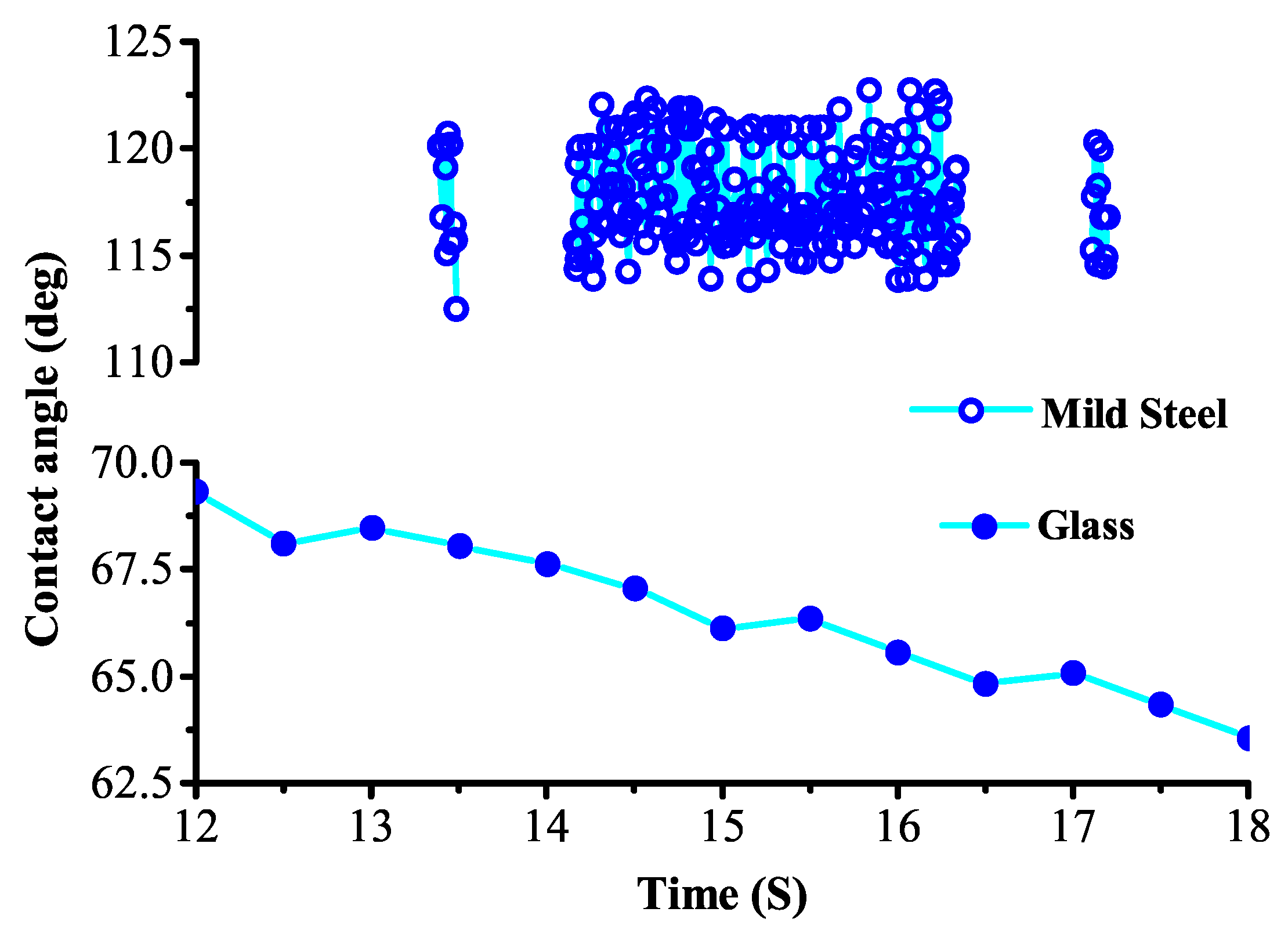
Figure 1 demonstrates the wetability of glass and mild steel substrates. The contact angle of water on glass substrates decreased with time due to the high wettability of glass substrate. The average contact angles were 59.72° for glass substrates and 117.84° for mild steel substrates. The measurement interval of mild steel substrate was much smaller than that of glass substrate. Thus, there are more data from mild steel substrate than from glass substrate.
Figure 1.
The wetability of glass and mild steel substrates.
Figure 1.
The wetability of glass and mild steel substrates.
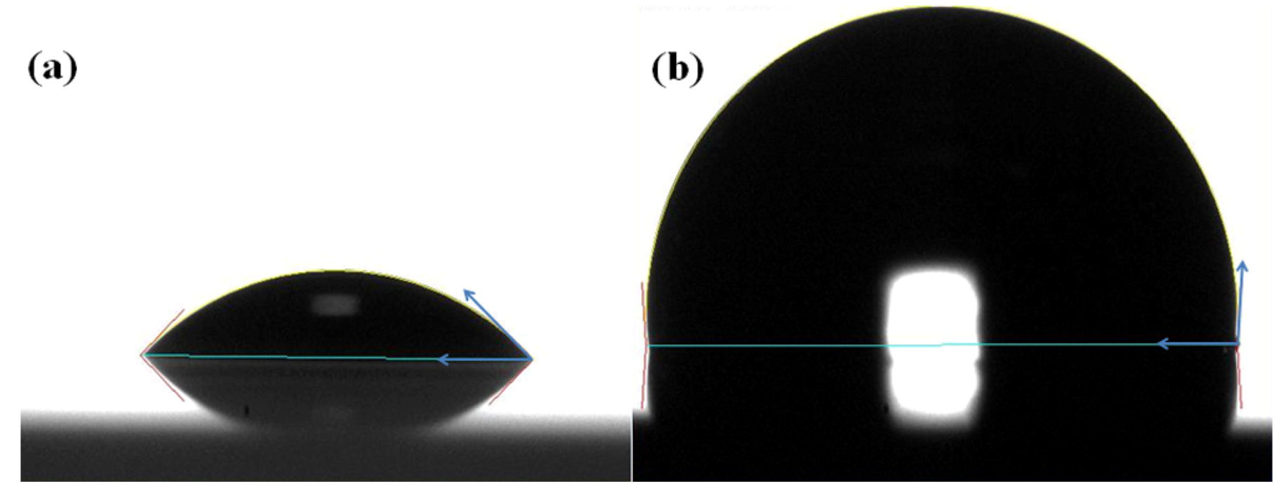
Figure 2 shows the contact angle image on (a) a glass substrate and (b) a mild steel substrate. The picture was taken one minute after the water droplet was placed on the appropriate substrate. The contact angle of glass substrates was smaller than that of mild steel substrates. This result indicated that wettability of glass substrates is higher than that of mild steel substrates since the wettability is defined as the inverse of the contact angle.
Figure 2.
The contact angle image of (a) glass substrates and (b) mild steel substrates.
Figure 2.
The contact angle image of (a) glass substrates and (b) mild steel substrates.
3.2. Roughness Measurement of Glasses and Mild Steel Substrates
The average roughness (Ra) of the glass, polished mild steel and gritted mild steel substrates measured by AlphaStep® D-120 Stylus Profiler was 0.013, 0.075 and 2.72 µm respectively.
Figure 3,
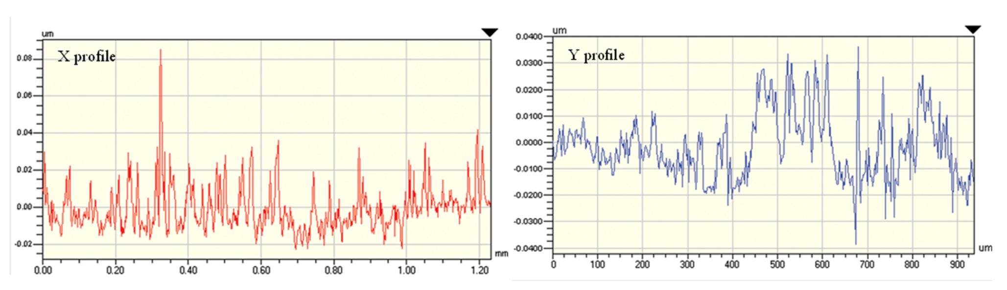
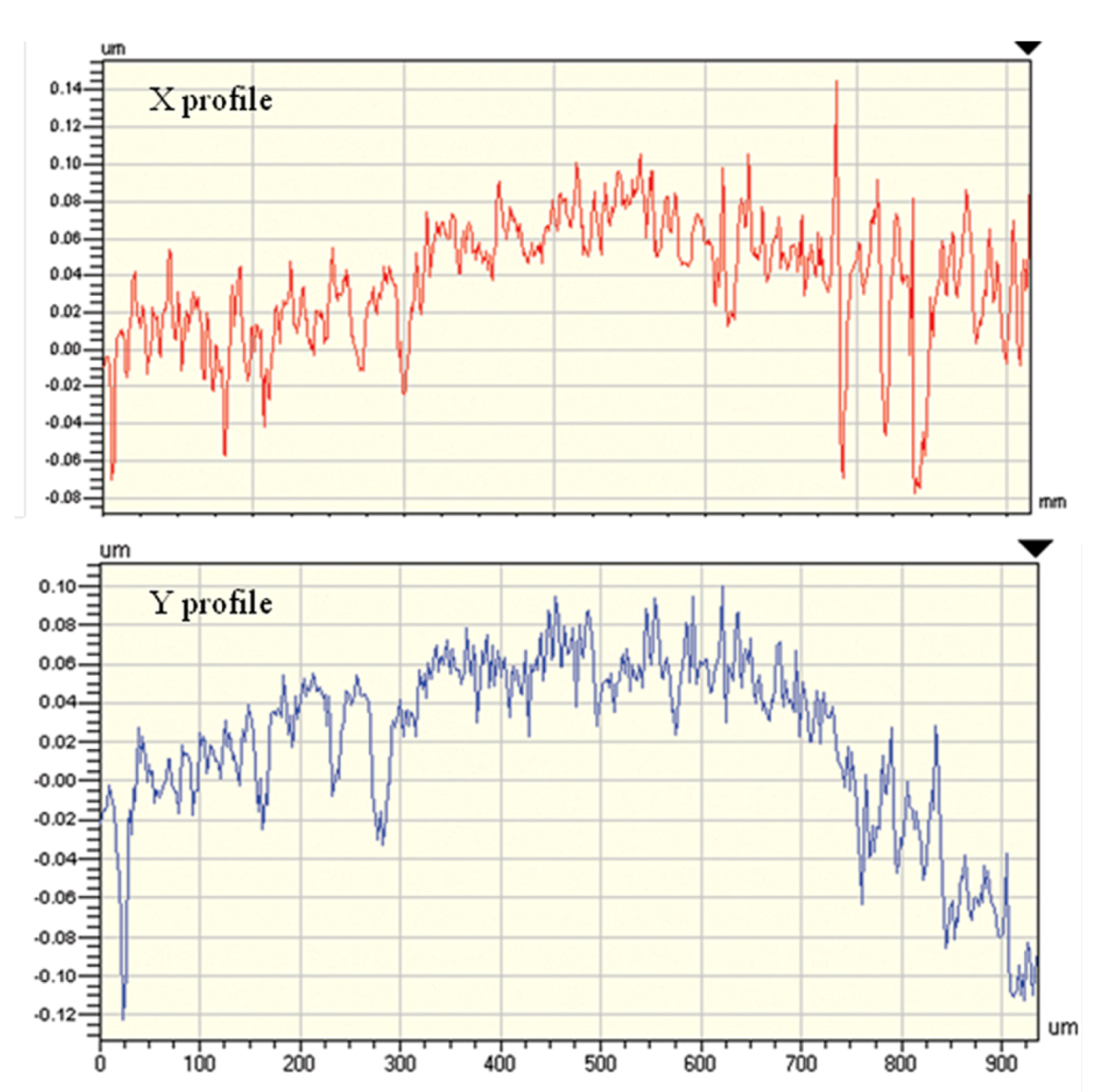
Figure 4 show the roughness profile of glass and mild steel substrates measured by a VECCO WYKO NT1100 non-contact optical surface profilometer (VECCO, NY, USA). The Ra was 0.01 µm and 0.03 µm for the glass and polished mild steel substrates, respectively. The roughness of glass substrates was the same as that measured by the AlphaStep® D-120 Stylus Profiler, while the roughness of mild steel substrates was smaller than that measured by the AlphaStep® D-120 Stylus Profiler. The difference between these two results may be attributed to the fact that the mild steel substrates were polished manually. Thus, the roughness of the mild steel substrates could be irregular due to lack of precision and control, while the glass substrates in the form of microscopy glass slides were in the as-received condition from the factory.
Figure 3.
The roughness profiles of glass substrates.
Figure 3.
The roughness profiles of glass substrates.
Figure 4.
The roughness profiles of polished mild steel substrates.
Figure 4.
The roughness profiles of polished mild steel substrates.
3.3. Single Splat Characterization by WYKO Surface Profiler and ContourGT
The disk splats at 20 cm SOD on the glass substrate were scanned using a WYKO surface profiler that are shown in
Figure 5,
Figure 6 respectively.
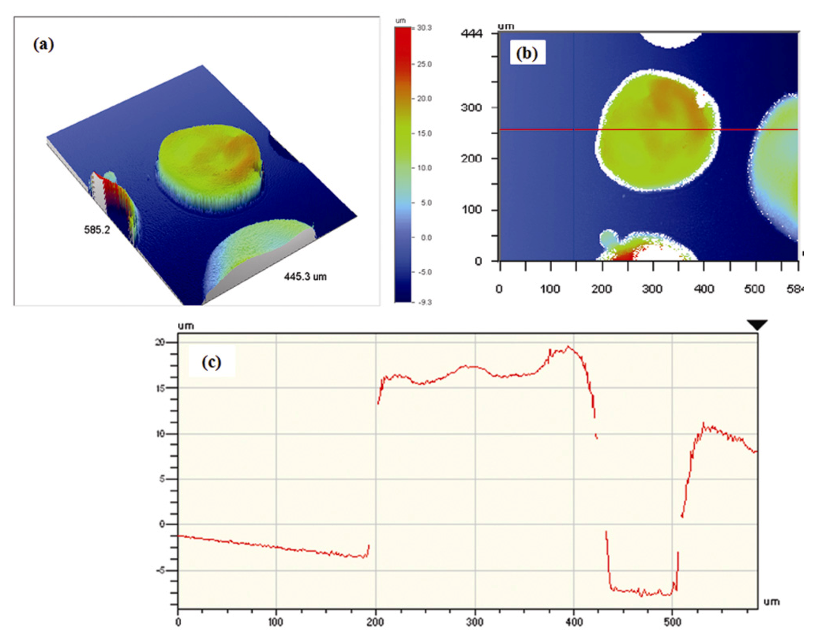
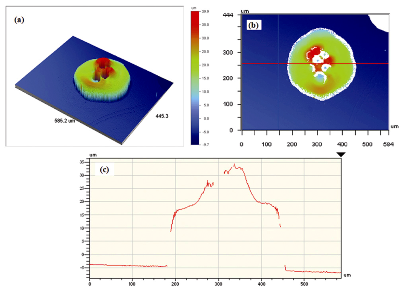
Figure 5a and
Figure 6a are three dimensional images of splats;
Figure 5b and
Figure 6b are top views of splat, while
Figure 5c and
Figure 6c are splat cross sections. There were bubbles in the center of the splat in
Figure 6. The physical measurements of the splashed splat were height = 8.72 µm, diameter = 250 µm, area = 49.1 × 10
3 µm
2 and volume = 1.95 × 106 µm
3. The corresponding measurements of the disc splat were height = 39 µm, diameter = 270 µm, area = 57.2 × 10
3 µm
2 and volume = 1.72 × 106 µm
3.
Figure 5.
Single splat scanned by WYKO surface profiler (a) 3D display; (b) top view and (c) cross section of splat.
Figure 5.
Single splat scanned by WYKO surface profiler (a) 3D display; (b) top view and (c) cross section of splat.
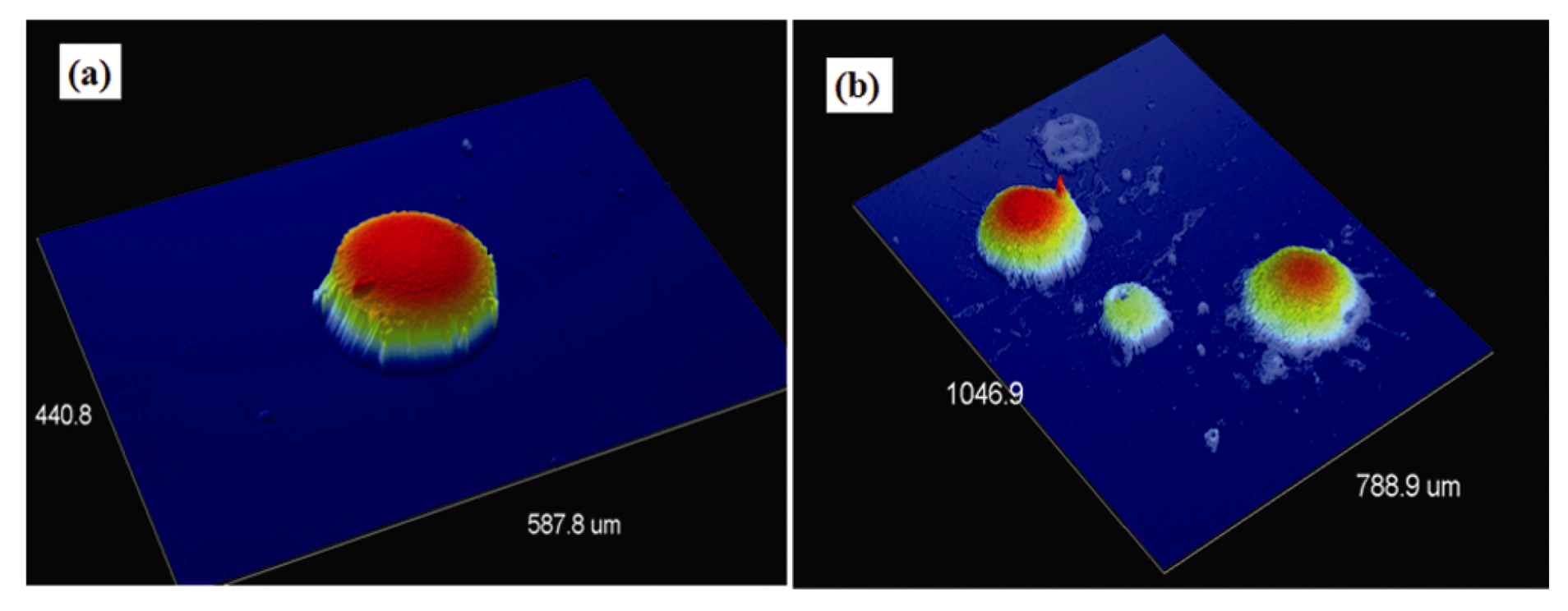
Single splats scanned using a ContourGT surface profiler for (a) disc splat and (b) splashed splat are depicted in
Figure 7. The ContourGT surface profiler can characterize a greater area in comparison to the WYKO surface profiler. The patching function of the ContourGT surface profiler allowed several splats to be imaged in one view. The image quality was also better than for the WYKO surface profiler.
Figure 6.
Splat scanned by WYKO surface profiler (a) 3D display; (b) top view and (c) cross section of splat.
Figure 6.
Splat scanned by WYKO surface profiler (a) 3D display; (b) top view and (c) cross section of splat.
Figure 7.
Single splats scanned by ContourGT surface profiler (a) disc splat and (b) splashed splat.
Figure 7.
Single splats scanned by ContourGT surface profiler (a) disc splat and (b) splashed splat.
3.4. Effect of SOD on the Morphology of EMAA Single Splats
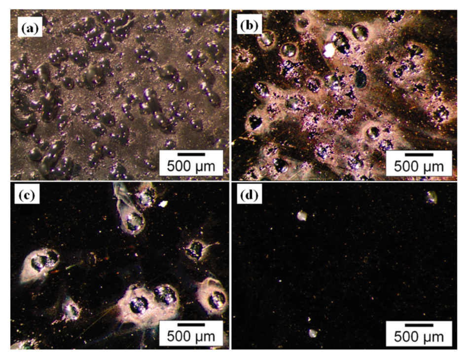
3.4.1. Morphology of EMAA Single Splats on Cold Substrates
The effect of SOD on the morphology of EMAA single splat impacts on glass substrates and mild steel substrates are shown in
Figure 8,
Figure 9 respectively. A major aim of the following discussion is to establish a physical model between the splat morphologies with respect to the SOD.
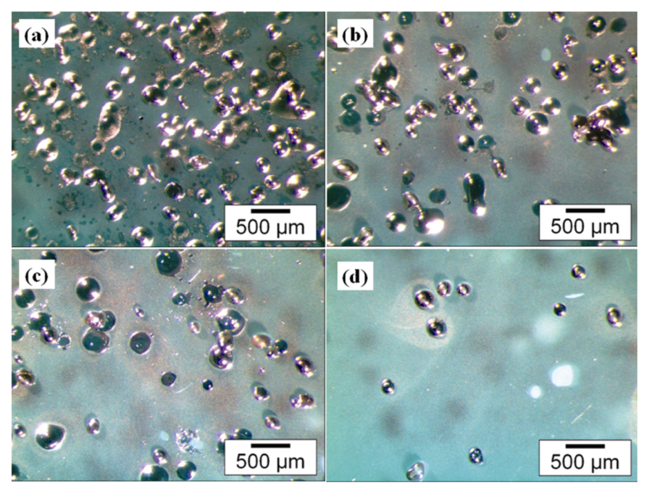
On the glass substrates, there were more semi-molten splats or spherical splats at 20 cm SOD,
Figure 8a. When the SOD was increased to 25 cm, more disc splats were observed,
Figure 8b. Increasing SOD to 30 cm resulted in more fingered splashes and fragmented splashes,
Figure 8c. Almost all re-solidified splats or spherical splats were revealed at 35 cm SOD,
Figure 8d.
For the mild steel substrates, there were more semi-molten splats or spherical splats at 20 cm SOD,
Figure 9a, which were similar to those features on the glass substrates. More fragmented splashes appeared at 25 cm SOD,
Figure 9b, which was due to (i) the higher thermal conductivity of the mild steel substrates and (ii) a high particle velocity in flight that led to high momentum energy. More disc splats and fingered splashes appeared at 30 cm,
Figure 9c and nearly all re-solidified splats or spherical splats can be observed in
Figure 9d. More fragmented splashes and spherical splats occurred on mild steel substrates than on glass substrates due to gas release from the mild steel substrate. This result reinforces the importance of substrate preheat treatment to create industrial thermal spray coatings. However, Fukumoto
et al. [
10] found that splat deposition on gold substrates changed very little between conditions of preheating and no preheating. In this case, the effect of surface chemistry on splat morphology was small, because gold is a noble metal that does not oxidize.
Increasing the SOD resulted in more spherical splats, as shown in
Figure 8,
Figure 9. In this case, the low velocity of FS and the rapidly decreased temperature of the jet with spray distance promoted conditions for re-solidification. Spray distances less than 40 cm are usually preferred to avoid particle re-solidification before impact [
26]. However there was a compromise condition since spray distances less than 35 cm were preferred to avoid particle re-solidification before impact.
A smooth, highly deformed, disc-like splat demonstrated in flight melting since the viscosity of the melting particles was sufficiently low to allow the preferred deformation upon impact. The spherical splat indicated the high viscosity of the melting particles, which were restrained from sufficient deformation upon impact. Such morphological behavior may also result from low impact velocity at high SOD, a higher surface tension coefficient at the melting point, as well as a larger than 90 degree contact angle.
The higher wettability and lower roughness of glass substrates compared with mild steel substrates which were discussed previously contributed to the less fragmentation of splats deposited on glass substrate than that on mild steel substrate.
Single splats are the building blocks of a thermal spray coating. The morphology of single splats is intrinsically related to the properties of thermal spray coatings, thus 25 cm and 30 cm SODs for glass substrates and steel substrates are meaningful and practical for the EMAA FS coating industry.
Figure 8.
Stand-off distance (SOD) effect on microstructure of splat and splash splat on glass substrates.
Figure 8.
Stand-off distance (SOD) effect on microstructure of splat and splash splat on glass substrates.
Figure 9.
SOD effect on microstructure of splat and splash splat on mild steel substrates.
Figure 9.
SOD effect on microstructure of splat and splash splat on mild steel substrates.
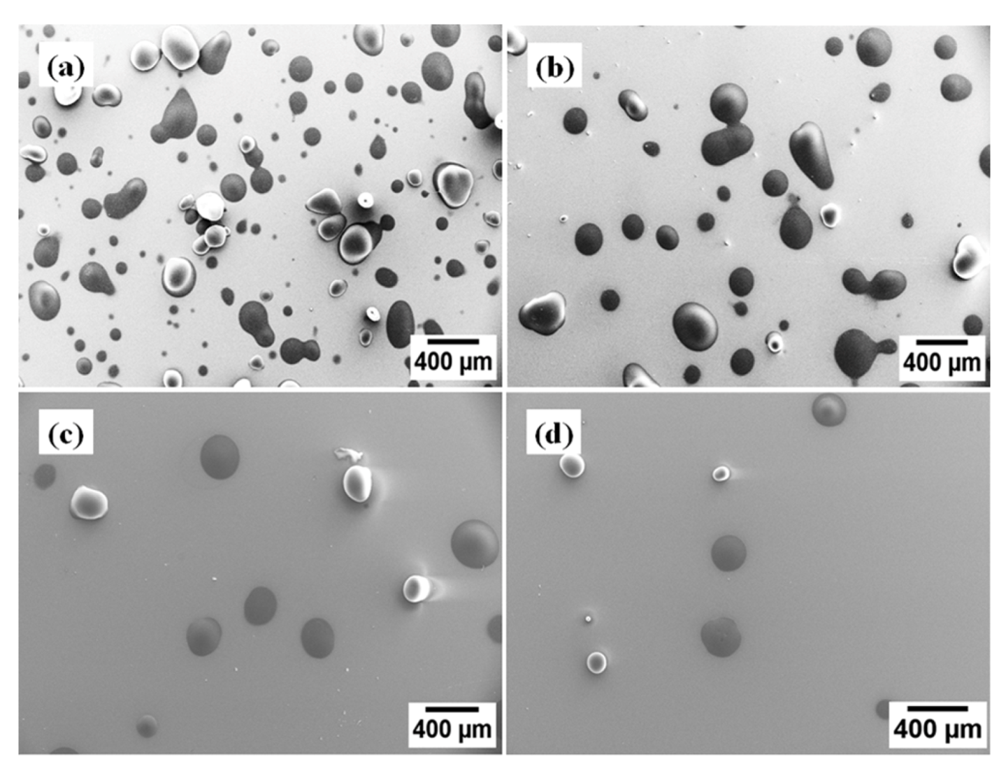
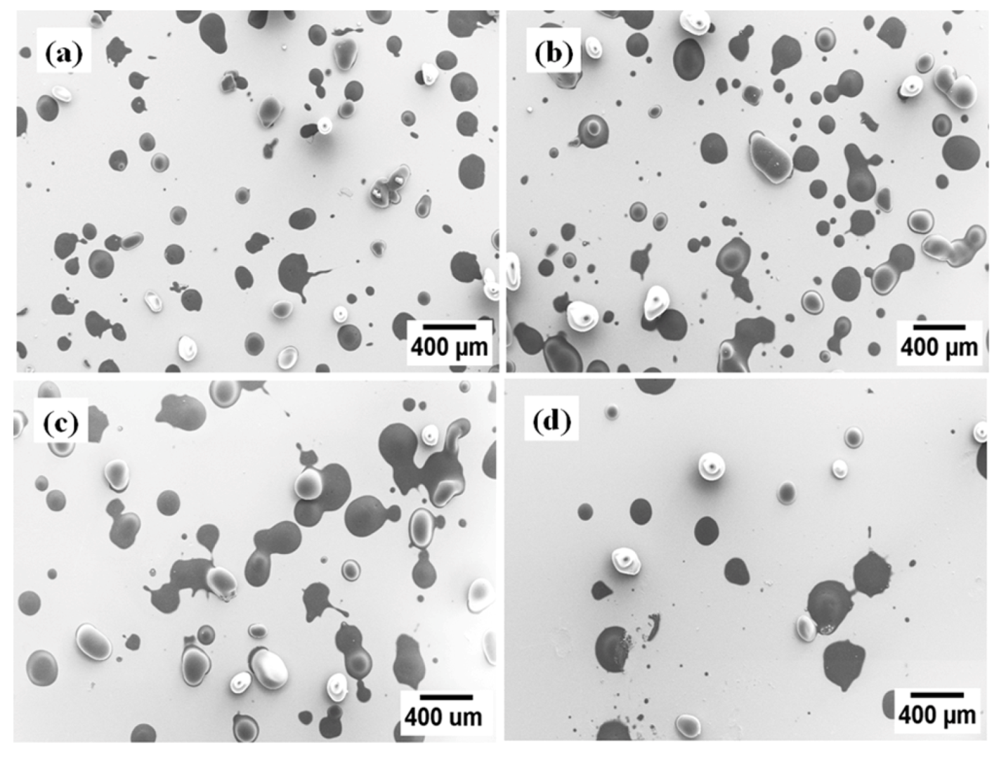
3.4.2. Morphology of EMAA Single Splats Deposit on Heated Substrates
Figure 10 depicts a single splat deposit onto heated glass substrates at (a) 15 cm; (b) 20 cm; (c) 25 cm; and (d) 30 cm stand-off distances. There were many unmelted splats and some splashing at 15 cm SOD in
Figure 10a. There were more resolidified splats at 25 cm and 30 cm SOD; as shown in
Figure 10c and
Figure 10d. The ideal SOD was determined to be 20 cm for heated glass substrates. The percentage of splats reduced on increasing the SOD. There were no bubbles in the splats thereby indicating that there were no condensates on unheated glass substrates as shown in
Figure 10.
Figure 10.
The single splat deposit on heated glass substrates at (a) 15 cm stand-off distance; (b) 20 cm stand-off distance; (c) 25 cm stand-off distance and (d) 30 cm stand-off distance.
Figure 10.
The single splat deposit on heated glass substrates at (a) 15 cm stand-off distance; (b) 20 cm stand-off distance; (c) 25 cm stand-off distance and (d) 30 cm stand-off distance.
Figure 11.
The single splat deposit on heated mild steel substrates at (a) 15 cm stand-off distance; (b) 20 cm stand-off distance; (c) 25 cm stand-off distance and (d) 30 cm stand-off distance.
Figure 11.
The single splat deposit on heated mild steel substrates at (a) 15 cm stand-off distance; (b) 20 cm stand-off distance; (c) 25 cm stand-off distance and (d) 30 cm stand-off distance.
Figure 11 demonstrates a single splat deposit on heated mild steel substrates at (a) 15 cm; (b) 20 cm; (c) 25 cm; and (d) 30 cm stand-off distances. There were more splashes on heated mild steel substrates than heated glass substrates as shown in
Figure 10 due to the difference of thermal conductivity between the mild steel and glass substrates [
27]. It is quite likely that more rapid freezing occurred on mild steel than on glass substrates due to the higher thermal conductivity of the steel. The thermal conductivity of the mild steel and glass substrates are 36–54 Wm
−1K
−1 and 1.09–1.2 Wm
−1K
−1 [
28,
29], respectively, thus the thermal diffusivity of the mild steel was higher than that of the glass substrates. The solidification of the splat bottom impeded the flow of the liquid above and resulted in splashing.
However, the surface of the heated mild steel substrates was much cleaner than the unheated mild steel substrates (
Figure 9) due to the effect of the surface chemistry. The gas release from the condensates of the substrate due to input heat from the particle at impact [
8,
9,
10] caused dramatic splashing. Thus, the surface chemistry of substrates played a more important role than the thermal conductivity of substrates in forming the splat morphologies.
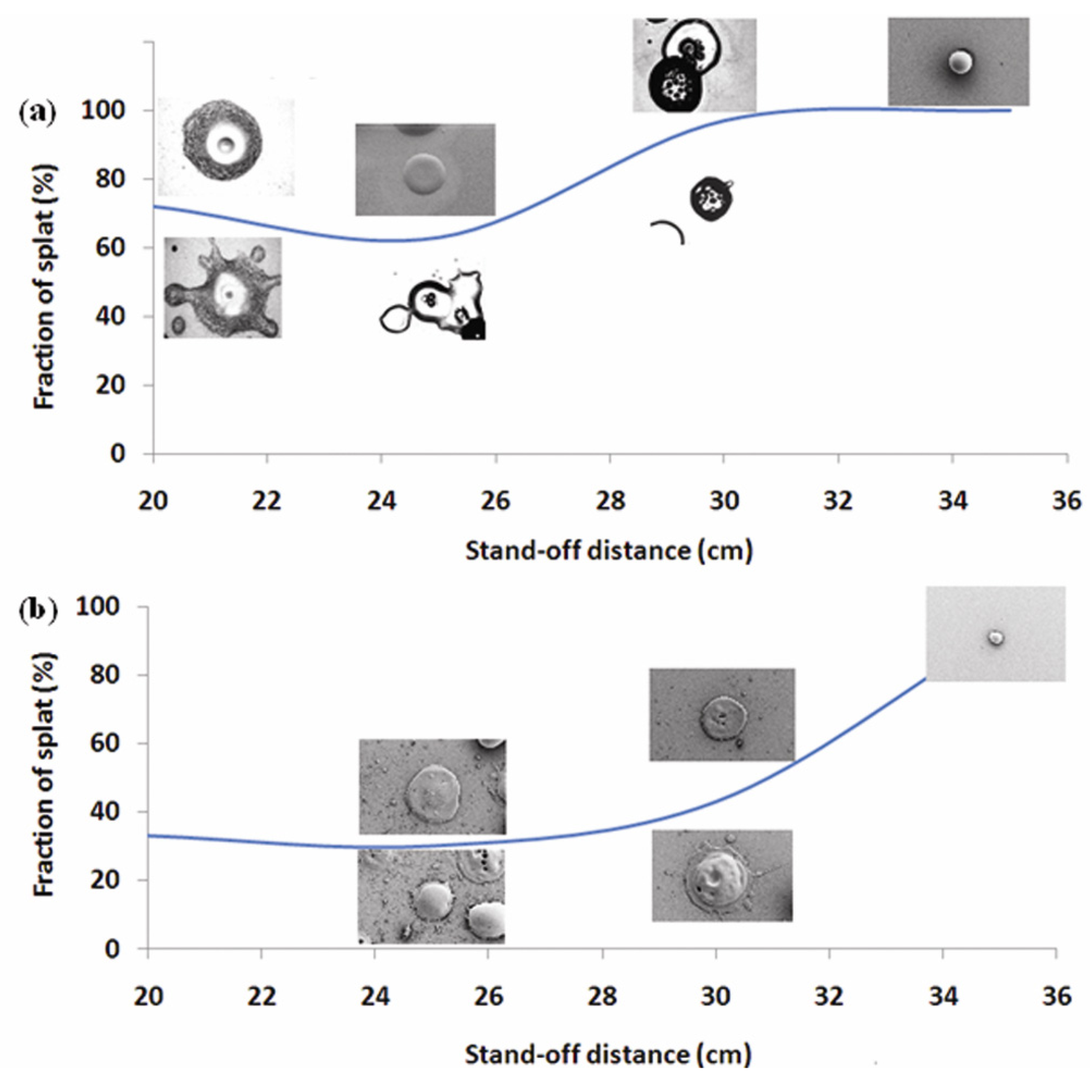
3.5. The Effect of SOD on Splat Fraction
Figure 12 demonstrates the effect of SOD on splat fraction. Splat fraction is the ratio of disc splat to splashed splat. The splat fractions on a glass substrate are 72%, 63%, 97% and 100% at 20, 25, 30 and 35 cm SOD, respectively,
Figure 12a. The splat fractions on a mild steel substrate are 33%, 30%, 43% and 93% at 20, 25, 30 and 35 cm SOD, respectively,
Figure 12b. Thus, the splat fraction on glass substrates was higher than that on mild steel substrates due to the lower thermal conductivity, higher wettability and lower roughness of the glass.
Figure 12.
SOD effect on splat fraction of unheated (a) glass substrates and (b) mild steel substrates.
Figure 12.
SOD effect on splat fraction of unheated (a) glass substrates and (b) mild steel substrates.
3.6. Modeling of TV, TS and VS Map
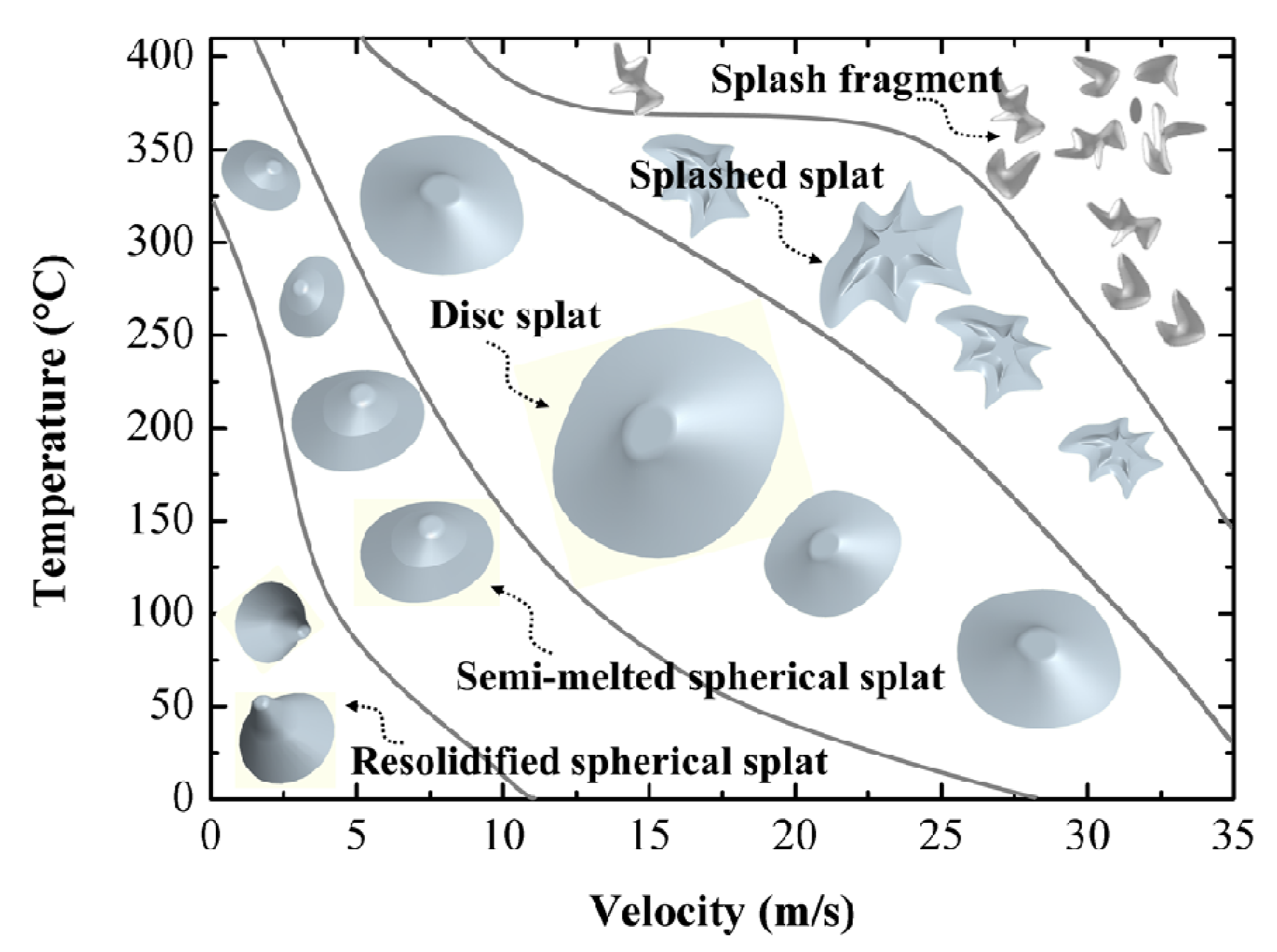
Figure 13 exhibits the temperature
vs. velocity (TV) map of EMAA single splats. There are five splat morphology zones according to this TV map. They are (i) resolidified spherical splat zone; (ii) semi-melted spherical splat zone; (iii) disc splat zone; (iv) splashed splat zone; and (v) splash fragment zone. The semi-melted spherical splats and resolidified spherical splats arose when both the particle velocity and temperature were low. The splashed splats and splash fragment were observed when the particle velocity and temperature were high. The disc splat can only appear when the temperature and velocity of particles were in an appropriate range. The highest temperature of EMAA particles was 400 °C The highest velocity of EMAA particles in propane FS was 35 m/s [
30,
31].
Figure 13.
Temperature–velocity (TV) map of EMAA single splats. The lines indicate the approximate fields where the splat morphologies are exhibited.
Figure 13.
Temperature–velocity (TV) map of EMAA single splats. The lines indicate the approximate fields where the splat morphologies are exhibited.
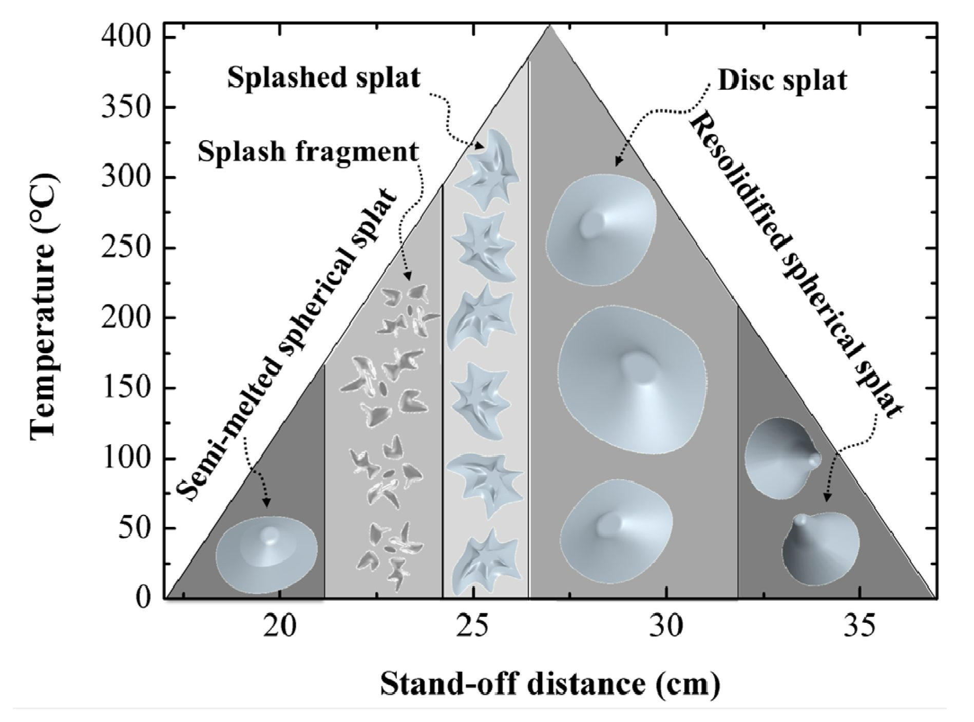
Figure 14 depicts the temperature
vs. stand-off distance (TS) map of EMAA single splats. The classification of splat morphology is indicated on the upper lines of the triangle. The semi-melted spherical splats occurred when the particles temperature was low and stand-off distance (SOD) was at 20 cm to 25 cm. The resolidified spherical splats arose when the temperature was low and the SOD is at 30 cm to 35 cm. Splashed splats and splash fragments were exhibited when the particle temperatures were high. They occurred between 20 cm and 30 cm SOD. The disc splats appeared when the temperature of the particles was in an appropriate range that depended on the velocity. The disc splats normally occurred between 25 cm and 35 cm SOD.
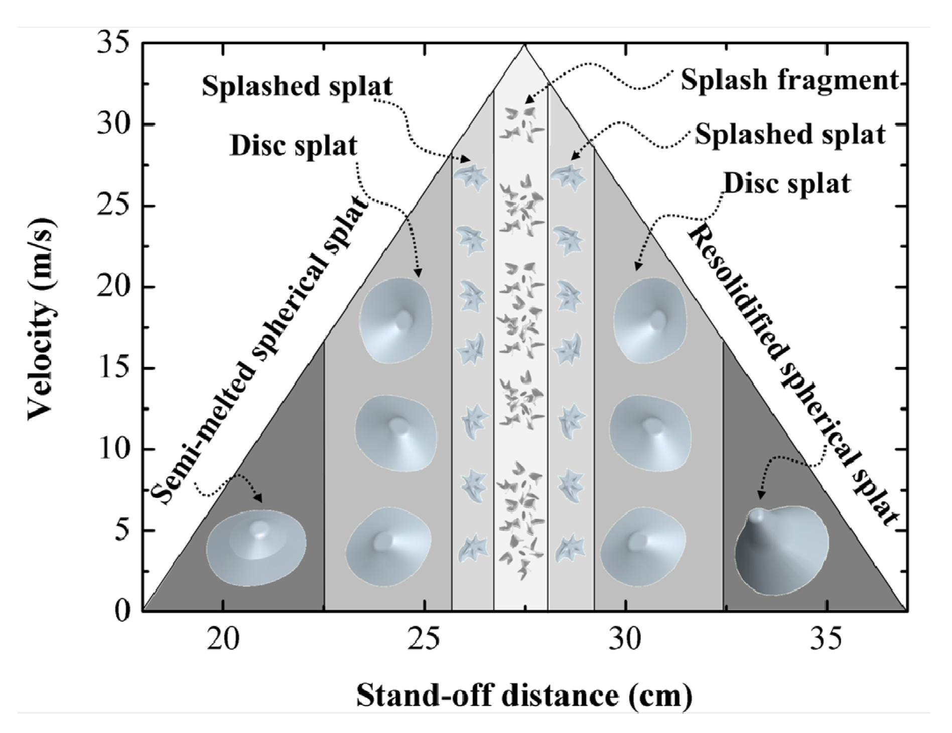
Figure 15 presents the velocity
vs. stand-off distance (VS) map of EMAA single splats. The classification of splat morphology is depicted on the upper lines of the triangle. Semi-melted spherical splats occurred when the particle velocity was low and stand-off distance (SOD) was from 20 cm to 25 cm. Resolidified spherical splats were exhibited when the velocity was low and the SOD was from 30 cm to 35 cm. Splashed splats and splash fragments were produced when the particle velocity was high. They occurred between 25 cm and 30 cm SOD. The splash fragments occurred at the highest particle velocity. The disc splats appeared when the velocity of the particles was in an appropriate range. The disc splats occurred between 20 cm and 35 cm SOD.
Figure 14.
Temperature–Stand-off (TS) map of EMAA single splats.
Figure 14.
Temperature–Stand-off (TS) map of EMAA single splats.
Figure 15.
Velocity–Stand-off (VS) map of EMAA single splats.
Figure 15.
Velocity–Stand-off (VS) map of EMAA single splats.
4. Conclusions
The lower wettability, higher roughness and higher thermal conductivity of mild steel substrates compared with glass substrates led to more fragmentation of splats deposited on mild steel substrate than that on glass substrate. However, the surface chemistry of substrates played a more important role than wettability, roughness and thermal conductivity in single splat morphology. Substrates heat treatment above transitional temperature significantly reduced the splashed splats.
The prime five morphologies of splats [
25];
i.e., (i) semi-molten splats; (ii) re-solidified splats; (iii) disc splats; (iv) splashed splats; (v) fragmented splashes, are modeled position on the temperature
vs. velocity map. The semi-molten splats and re-solidified splats arose at lower temperatures and velocities, which corresponded to SOD shorter than 25 cm and SOD longer than 30 cm, respectively. The disc splat was formed at either higher temperatures but lower velocities or moderate temperatures and velocities; which corresponded to SOD’s of 25 cm and 30 cm, respectively. The fingered splash appeared at higher temperatures and velocities that corresponded to SODs of 25 cm and 30 cm. The fragmented splash occurred at higher velocities under a wide range of temperature conditions.
This study provided practical guidance about the nature of how prime spray variables influenced processing/morphology relationships.


