1. Introduction
Zinc sulphide is a non-toxic semiconductor of the II–VI group with a good band gap. It has excellent chemical resistance and thermal stability. The band gap of zinc sulphide is about 3.68 eV. This makes it a potential candidate to replace cadmium sulphide in the hetero transition of CdTe/CdS and CdS/CIGS solar cells. The band gap of ZnS (3.68 eV) is larger than that of CdS (
E = 2.42 eV), which allows the use of ZnS as an optical window for ZnS/CdTe or ZnS/CdS/CdTe cells. Zinc sulfide has an advantage in delivering high-energy photons in the absorbent material and reduces their interim loss, which improves the short-circuit current in solar cells. Possessing such characteristics, ZnS is widely used for manufacturing various optical devices and is of interest not only as an individual semiconductor material but also as one of the components in cascade solar cells [
1,
2,
3,
4,
5,
6].
Zinc sulphide is obtained mainly by chemical deposition from the gas phase [
7], high-temperature pressing of zinc sulphide powder [
8,
9] and chemical deposition from aqueous solutions [
10,
11,
12]. These techniques require a considerable amount of energy for the synthesis of zinc sulphide at high temperatures or special conditions of annealing.
This work has shown the possibility of electrodeposition of zinc sulphide films of specified stoichiometric composition from the aqueous solution. The advantages of technical electrochemistry and alternating power current are used. The composition and structure of zinc sulphide films obtained by the electrochemical method depending on the conditions of deposition are studied.
The aim of the work is to obtain thin films of zinc sulfide by using the industrial alternating current with 50 Hz power frequency according to the two-electrode scheme.
2. Experimental Details
The electrochemical behavior of Zn(II) and ions in aqueous solutions was investigated by using cyclic voltammetry. The electrochemical measurements were made in a three-electrode cell at room temperature using the universal potentiostat-galvanostat Gill AC (ACM Instruments, Cumbria, UK). The disk glass-carbon electrode (S = 0.07 cm2) was used as a working electrode and Pt-wire as a contrary electrode. All potentials are shown with reference to (Ag/AgCl)/KCl sat) electrode. The potential sweep was made in the 0 V to −2.0 V range in the cathodic direction (forward movement) and −2.0 V to +2.0 V in the anodic direct (backward movement) with 20 mV/s velocity.
Electrodeposition was performed in a two-electrode cell with stirring. The industrial alternating current was supplied with the frequency of 50 Hz by using the laboratory autotransformer, diode and 7.5 kilohm resistor. The average current density was 8 mA/cm2and was registered by В7-35voltmeter. Zinc sulfide films were electrodeposited onto the flourine doped tin oxide glass (FTO/glass) substrate for 45 min at 70 °C and 30 °C from a solution containing 0.1 M tartaric acid (C4H6O6), 0.01 M zinc sulfate (ZnSO4), 0.01M sodium sulfite(Na2SO3), and 0.01 M sodium thiosulfate (Na2S2O3*5H2O), pH = 2–2.05. Sodium sulfite was used to prevent the formation of S and S due to disproportionate amount of thiosulfate ions. After electrodeposition, the films were rinsed in water, dried in air and annealed in air at 350 °C for 30 min.
Samples of films prepared under different conditions were investigated to determine the elemental composition and surface morphology by SEM (JSM-6610, JEOL Ltd., Tokyo, Japan) and AFM (JSPM-5200, JEOL Ltd., Tokyo, Japan).
The chemical composition of electrodeposited films was determined by X-ray attachment to electron microscopy (JSM-6610, JEOL Ltd., Tokyo, Japan).
Optical properties of the resulting samples were examined by the spectrometer Helios UV-Visible V7.00 (Helios, London, UK), with the possibility of registering the transmittance in the wavelength range from 190 nm to 1000 nm. XRD measurement was made with device DRON-4 with iron irradiation (Bourevestnik, St. Petersburg, Russia).
3. Results and Discussion
There are basic electrochemical reactions of thiosulfate ion in acidic solutions [Reactions (1)–(3)] [
13]. At high sodium thiosulfate concentrations, the process of disproportionate of
to S and
is possible to achievethrough Reaction (2). The most likely anode reaction at high anode positive potentials is the reaction of thiosulfate ion oxidation according to Equation (3).
Zinc ions in simple salt solutions are involved in reduction-oxidation reactions with the transfer of two electrons [Reactions (4) and (5)].
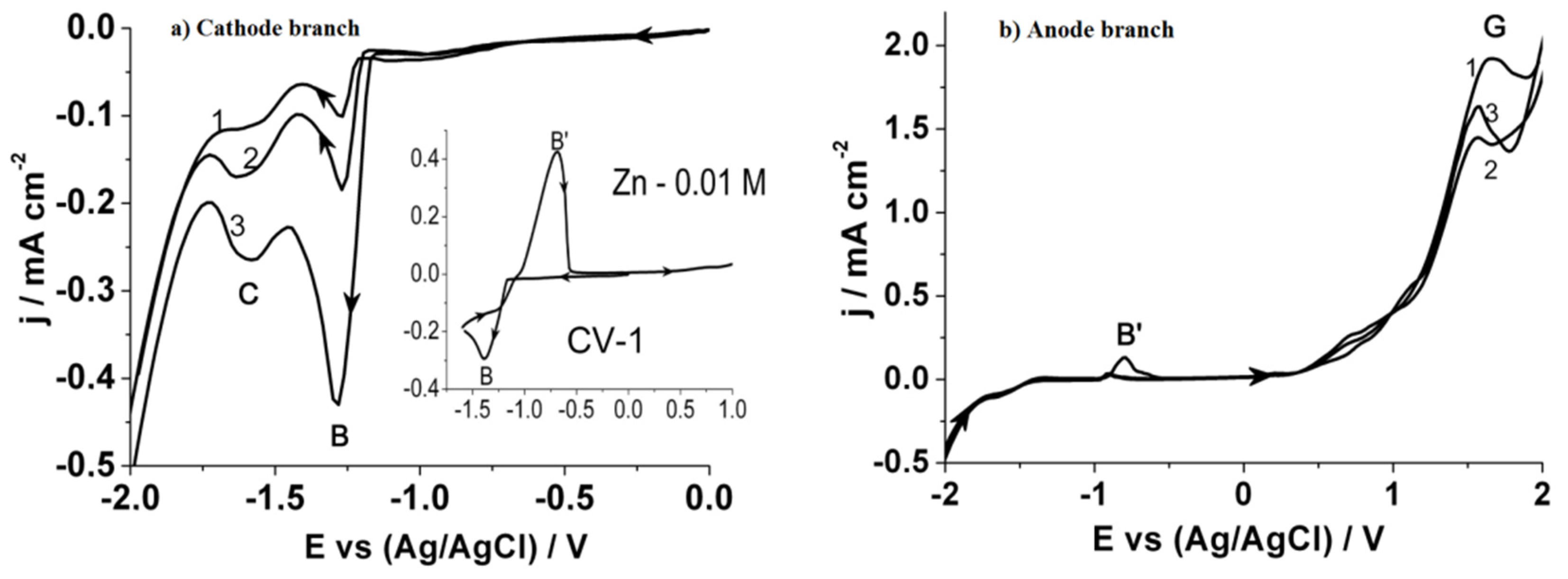
Figure 1 compares cyclic voltammetry curves of reduction on a glass-carbon electrode from the electrolyte. On the simultaneous electro-reduction of zinc and thiosulfate ions from a simple salt solution in the cathode region (
Figure 1a), one observes two peaks of reduction current in the potential range (B): (1) −1.15 ÷ −1.45 (peak B) corresponds to the process of Zn(II) reduction to Zn
0, just as in
Figure 1b; (2) −1.45 ÷ −1.7 (peak C) corresponds to the process of formation of zinc sulfide compounds according to Reaction (6).
In the case of backward potential sweep, the anodic part of the potentiodynamic curve (
Figure 1b) shows an additional oxidation peak (B’) with a maximum at −0.75 potential, according to Reaction (4). It appears when the concentration of Zn(II) ions exceeds that of sodium thiosulfate, and the elemental zinc, which has not reacted with sulphur on the electrode, starts to be oxidized. The oxidation of thiosulfate ions begins at high positive potentials [Reaction (3)] (peak G).
Based on the voltammetry analysis, it is concluded that zinc sulphide deposition can only be implemented while maintaining a strongly negative constant potential. To avoid this, the method of electrodeposition according to the two-electrode scheme using pulsed current (8 mA/cm2) is offered.
Table 1 lists the results of the elemental analysis of zinc sulfide films obtained at 70 °C by such a process as an average of three determinations at different points of the surface. Deviations from the average value are of different magnitudes. It is found that electrodeposition by pulse current makes it possible to obtain films with the composition close to stoichiometric (
Table 1 and
Table 2). However, it has been revealed that the results depend greatly on the deposition temperature.
At 70 °C, there is a considerable scatter in the data, and the average deviations in some cases are greater than ±6.68 at.%. This is due to the formation of colloidal sulfur in the electrolyte at high temperatures and prolonged electrolysis, which is also involved in the process. Therefore, further research has been carried out at 30 °C when the electrolyte remains transparent for a long time.
Table 2 lists the data on the elemental analysis of ZnS films obtained at these temperatures. The deviation from average values does not exceed ±0.75 at.%. In this case, there is a slight increase in the sulfur content with respect to the Zn:S = 1:1 ratio.
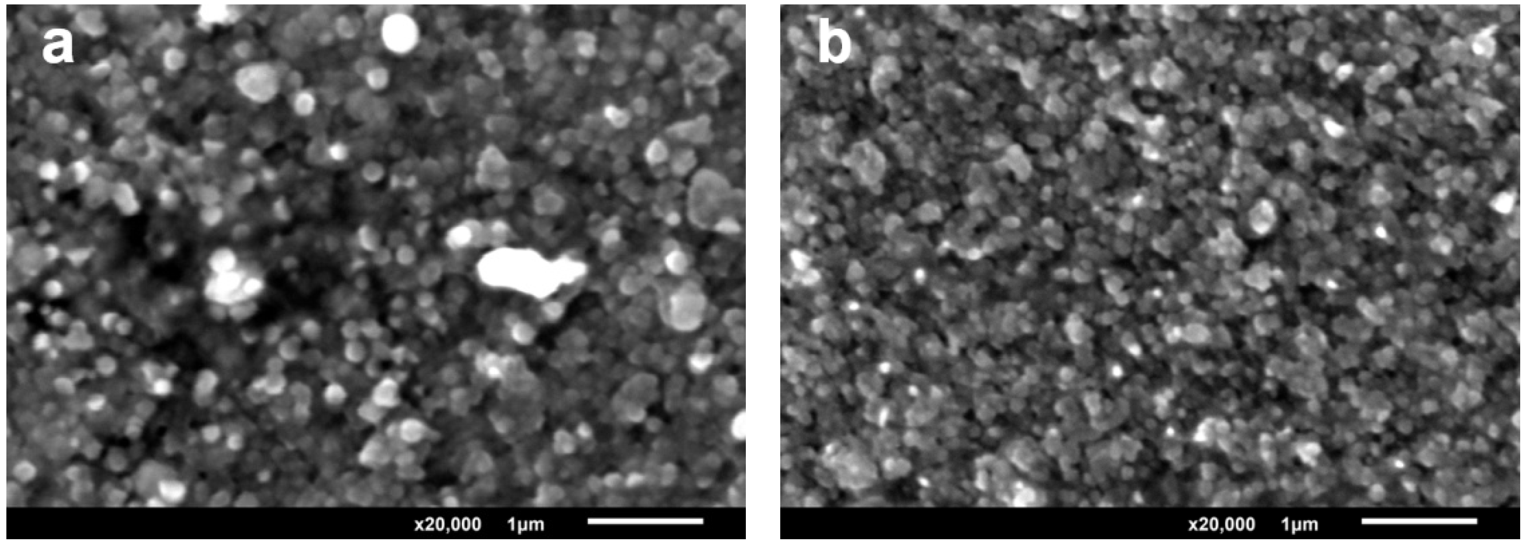
Figure 2a,b show the micrographs (magnification 20,000×) of the film surface. Data on the study of the surface of annealed films show significant densification of grains and formation of ordered structure resulting from the annealing of zinc sulfide films.
During pulsed deposition at 70 °C, the coating is uniform but has micro cracks which increase on annealing. During pulse-current deposition at 30 °C (
Figure 2b), the surface coating is dense and one observes smaller ZnS crystals with the sizes of 100 nanometers or less.
The thickness and optical properties were investigated for the films obtained at 30 °C.
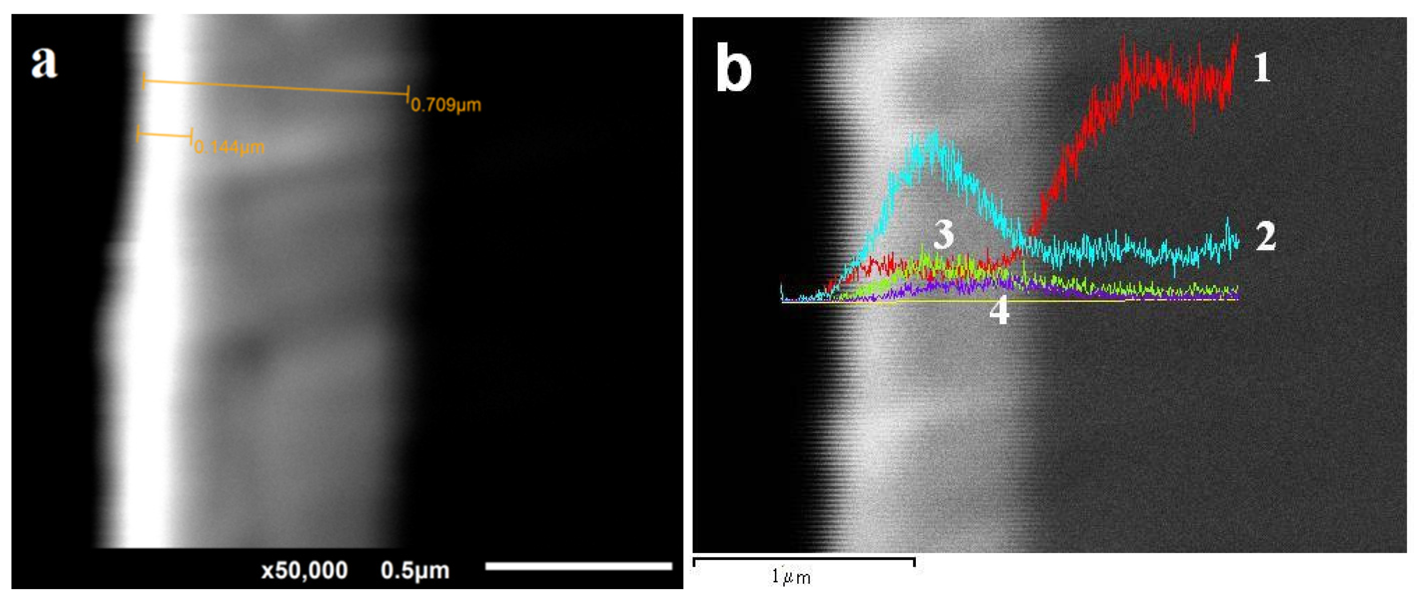
The film thickness was determined by the “cross-section” method using JEOL IB-09010CP (JEOL Ltd., Tokyo, Japan). As shown on the micrographs (
Figure 3a), the thickness of zinc sulfide films is 140–160 nm.
The total thickness of the coating together with the SnO
2 conductive layer is less than 1 μm.
Figure 3b shows the distribution of elements over the film thickness. It is seen that the maximum of sulfur and zinc falls on the deposited part of the film. The substrate of the conductive glass coating exhibits a uniform distribution of tin, and silicon is identified in the glass as the main component. The n-type conductivity for all ZnS films is determined by the method using a thermal probe.
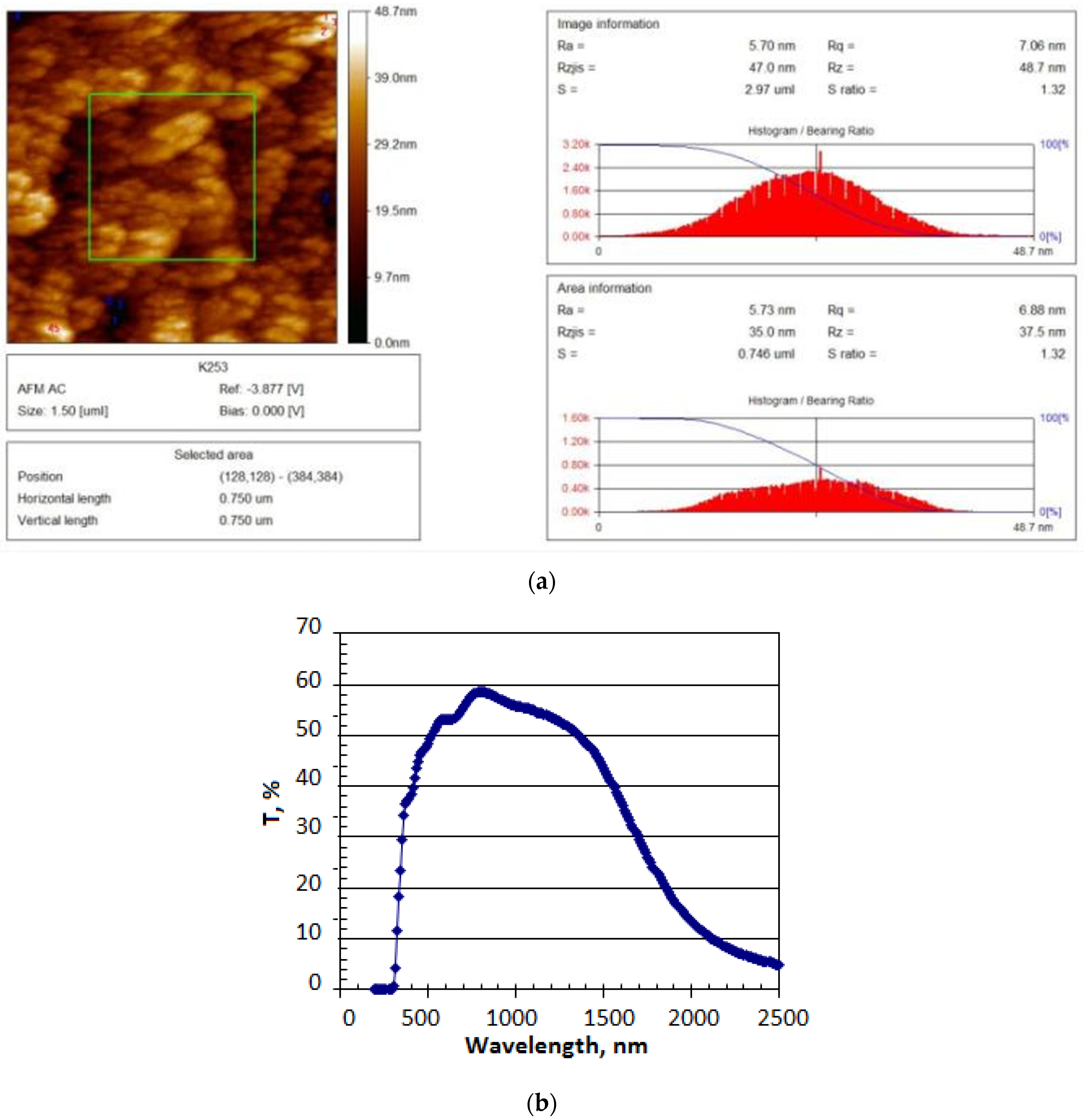
The surface morphology has been characterized by using the atom force microscope JSPM-5200 (JEOL Ltd., Tokyo, Japan) and it is shown in
Figure 4a.
The studies show that the surface is uniformly coated with fine ZnS particles. The smallest ZnS particle has a 5.7 nm diameter, and its height is 39 nm. Large ZnS particles are composed of smaller ones, their maximum diameter being less than 115 nm. The substrate topography of ZnS/F:SnO
2/glass has been studied using a three-dimensional (3D) image. The film thickness is 200 nm.
Figure 4b shows that ZnS films have high transmittance in the 400–2000 nm wavelength range and cover the entire visible spectrum and the near-infrared region. The absorption band edge corresponds to a 320 nm wavelength. Based on the transmittance spectra, the band gap of ZnS films is determined to be 3.8 eV.
The electrodeposited films have n-type conductivity. This shows great possibilities of using electrodeposited zinc sulfide films as an optical window in the cascade of thin-film solar cells.
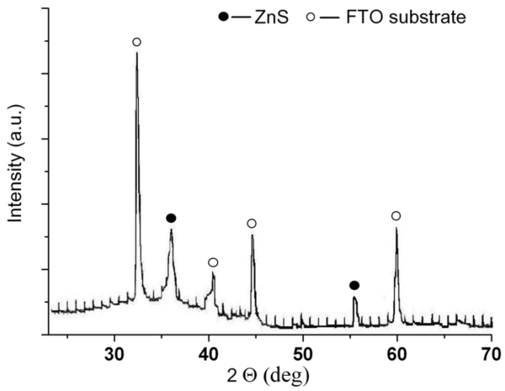
The structure of ZnS film after annealing was determined by using X-ray analysis. In
Figure 5, the X-ray spectra of electrodeposited ZnS film are shown and theyindicate a phase of ZnS (ASTM 10-434). The film is so thin that the reflexes of the FTO substrate at the X-ray spectracan be seen.


