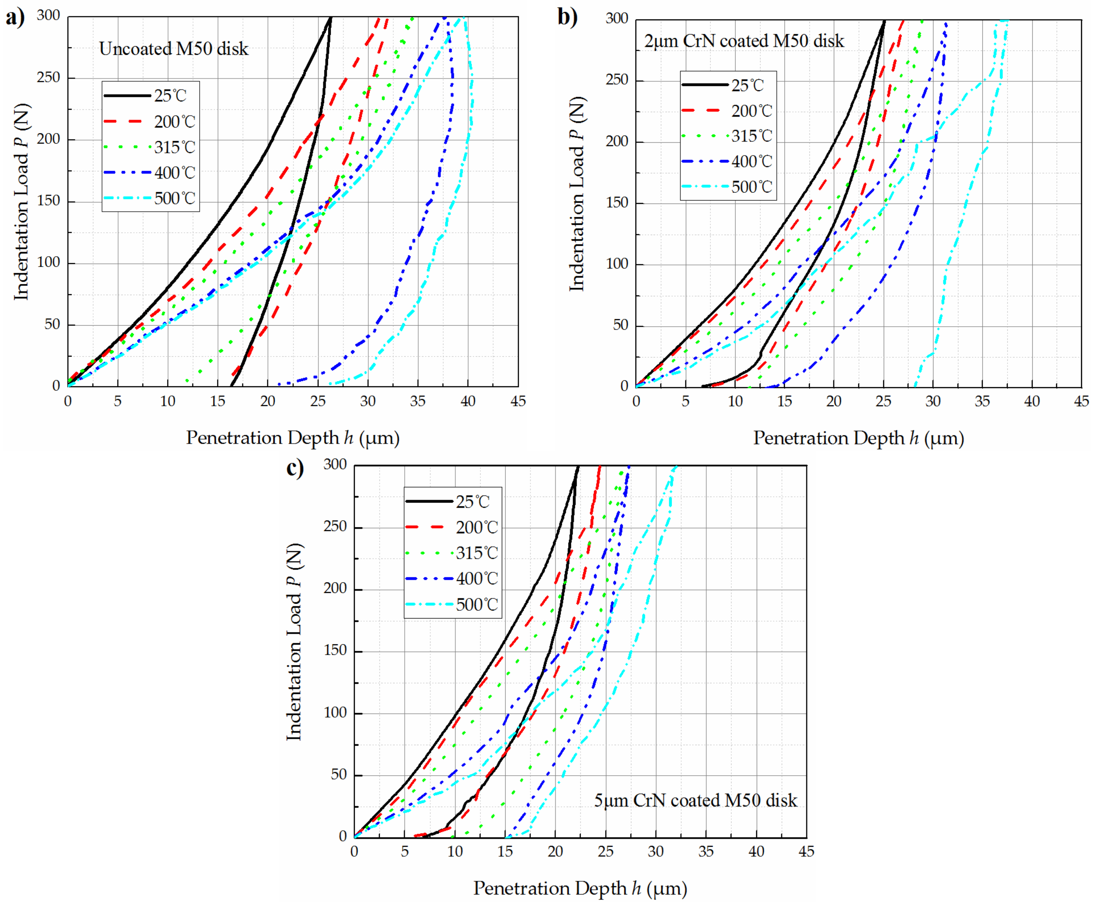
3.1. Indentation Tests at Elevated Temperatures
Elevated temperature indentation test results of uncoated M50 disks, 2 μm CrN coated M50 disks and 5 μm CrN coated ones are shown in
Figure 3.
Using Equations (1)–(5), hardness of M50 substrate,
Hs, and composite hardness of CrN coated M50 disks,
Hsys, were calculated from the load–depth curve shown
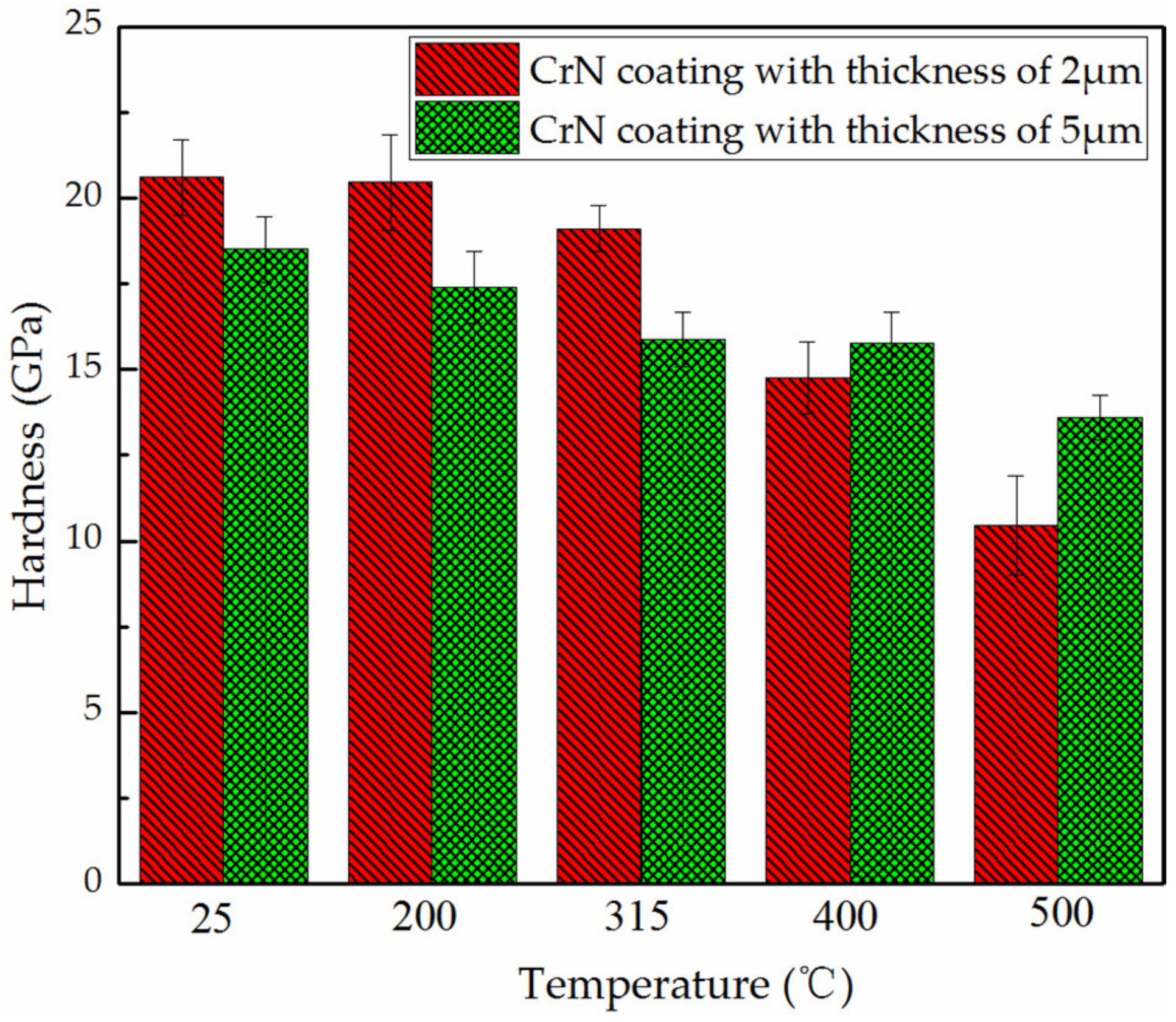
Figure 3. Then, using Equation (6), the absolute hardness of 2 μm CrN coating and 5 μm CrN coating were calculated, as presented in
Figure 4. In general, CrN coatings with all thicknesses showed a decreasing of hardness with temperatures. When the tested temperature was below 315 °C, the hardness of 2 μm thick CrN coating was higher than 5 μm thick CrN coating. However, when the tested temperature was above 400 °C, the 5 μm thick CrN coating had higher values in hardness. The 2 μm thick CrN coating had reduction of 49% in hardness values when the temperature increased from 25 to 500 °C. By comparison, the 5 μm thick CrN coating only had a reduction of 26%. It can be concluded that a thicker CrN coating would be helpful in maintaining the stability of surface hardness in high temperatures.
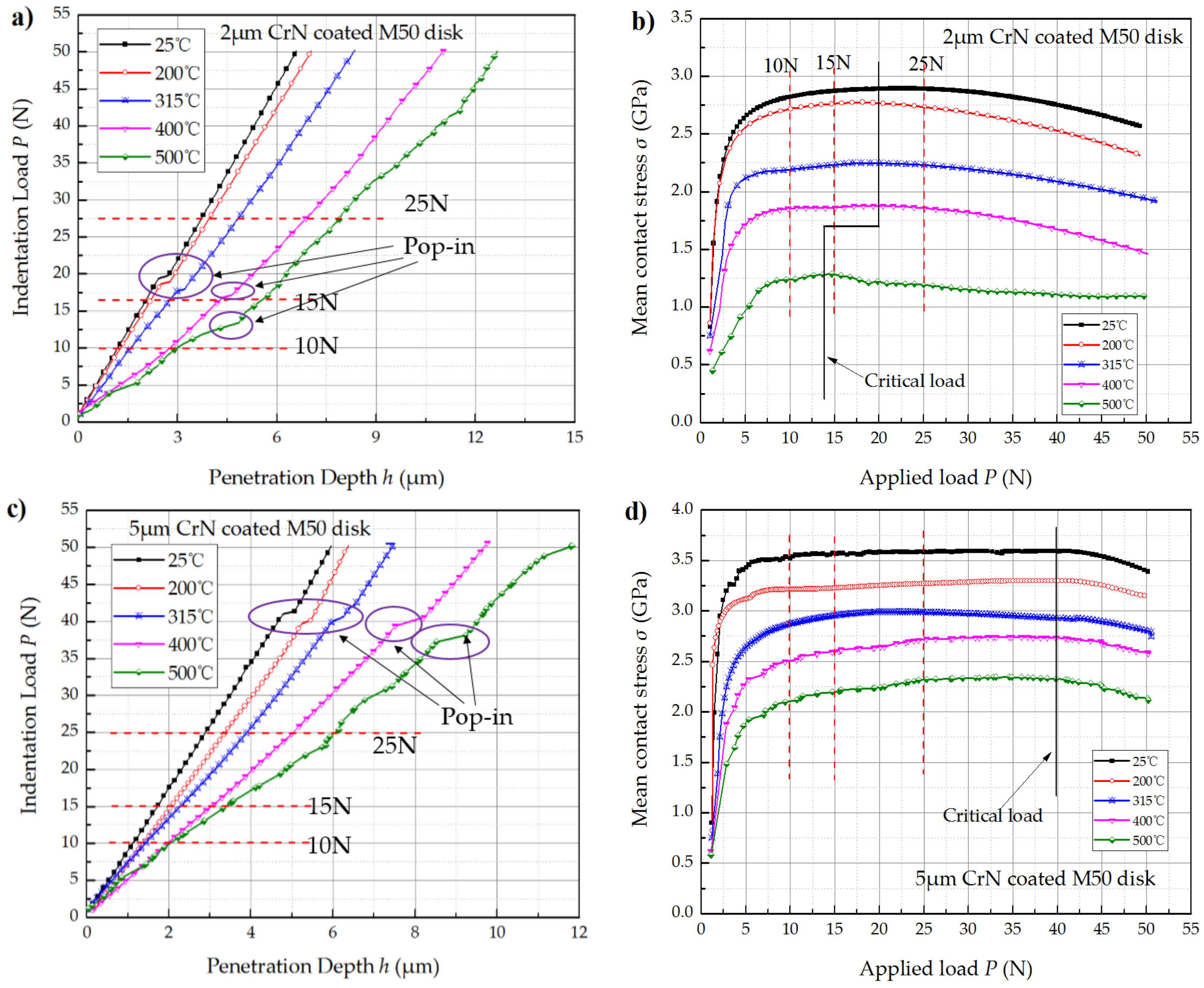
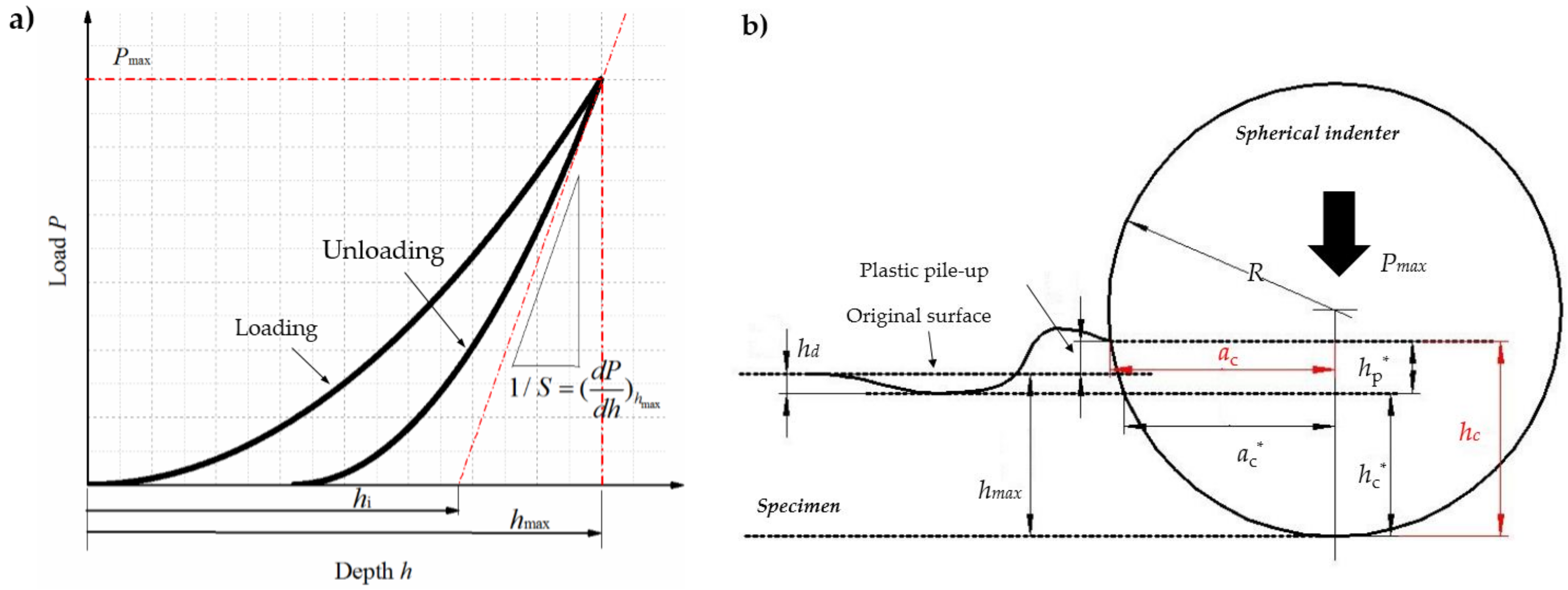
Figure 5 presents the loading curves and corresponding contact stress curves of 2 μm CrN coated M50 disks and 5 μm CrN coated ones in the load range of 1–50 N. The contact stress during indentation tests can be calculated using the following equation [
23]:
where σ is mean contact stress, and
ac is the contact radius during indentation.
In
Figure 5a,c, the loading curves were continuous up to a certain load, at which a sudden displacement burst occurred, indicating the occurrence of “pop-in” behavior. According to Shao [
24], the indentation stress-induced phase transition with material volume reduction (i.e., coating cracking) was the prerequisite to “pop-in” behavior. Hence, the indentation load, corresponding to the appearance of a “pop-in” event, could possibly be considered as an evaluation tool of load bearing capacity for the coating–substrate system. In another aspect, as shown in
Figure 5b,d, it was found that the contact stress reached its maximum values at this indentation load. The external load corresponding to the “pop-in” behavior was named as the load bearing capacity,
Lb, for a coating–substrate system.
It can be concluded that the load bearing capacities of CrN coated M50 disks decreased with temperatures. As illustrated in
Figure 5a,b, for the 2 μm CrN coated M50 disks, a normal load of 10 N was always less than its load bearing load bearing capacity,
Lb, in temperature range of 25–500 °C. However, an external load of 15 N was higher than its load bearing capacity when the temperature was elevated to 500 °C. An external load of 25 N was always higher than its load bearing capacity at any temperature. As illustrated in
Figure 5c,d, for the 5 μm CrN coated M50 disks, an external load of 10 N, 15 N or 25 N was always less than its load bearing capacity in temperature range of 25–500 °C.
3.2. Tribological Responses
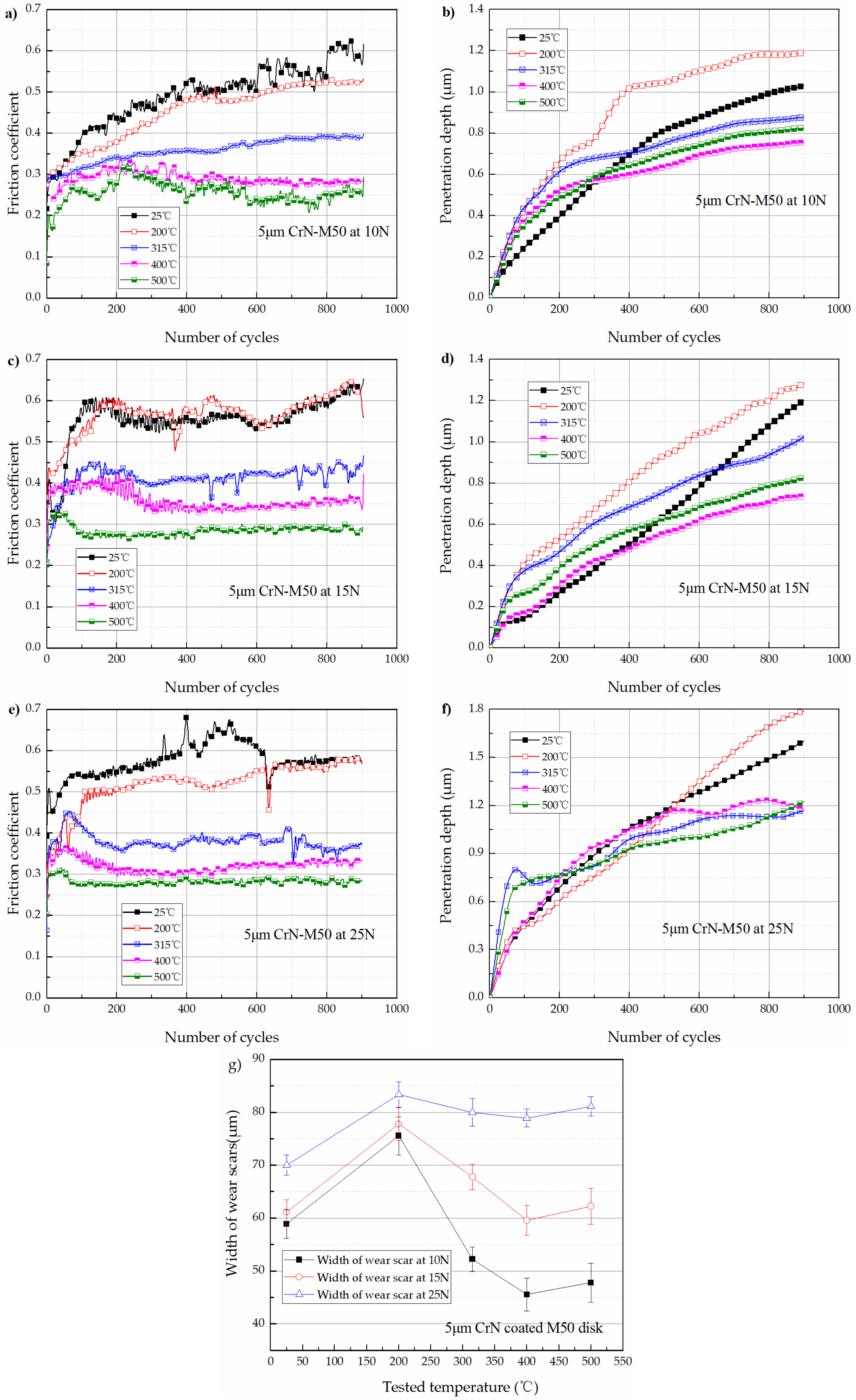
Figure 6a–f shows the friction coefficient curves and penetration depth during wear test of 5 μm CrN coated M50 disks as a function of temperatures under the tested loads of 10 N, 15 N, and 25 N. The variation of width of wear scars with temperatures is depicted in
Figure 6g.
As illustrated in
Figure 6a,c,e, running-in was presented by an increase of the friction coefficient during first several dozens to hundreds of cycles for all measured temperatures and loads. In the running-in stage, the friction force is mainly contributed to deform and fracture the contact asperities [
25]. Due to the lower hardness of the coating material at higher tested temperature, it would take less number of cycles for the friction coefficient to reach the steady stage.
For 5 μm CrN coated M50 disks tested under each load, the stable values of friction coefficient were all found to be decreased with temperatures. At the temperatures of 25 °C and 200 °C, the friction coefficient was determined to be about 0.6. However, it decreased to 0.4 at 315 °C, then gradually decreased to the lowest value of 0.3 at the highest temperature of 500 °C.
As shown in
Figure 6b,d,f, the variation trends of penetration depth at the temperatures above 315 °C were quite different from those at the temperatures below 200 °C. Due to the lower hardness of CrN coating at high temperatures, the penetrate depth increased more sharply at the temperatures above 315 °C than at the temperature below 200 °C in first 300 cycles. After 300 cycles of relative sliding, the penetration depth went on increasing linearly with distance at the temperatures below 200 °C, however, was much slowed down the temperatures above 315 °C. Meanwhile, the fluctuation in friction coefficient with sliding distance was also weakened when the tested temperatures were equal or above 315 °C. According to Polcar [
11], the reduction of penetration depth at the temperatures above 315 °C might contributed to the self-lubricant function of the formed chromium oxide tribo-layer.
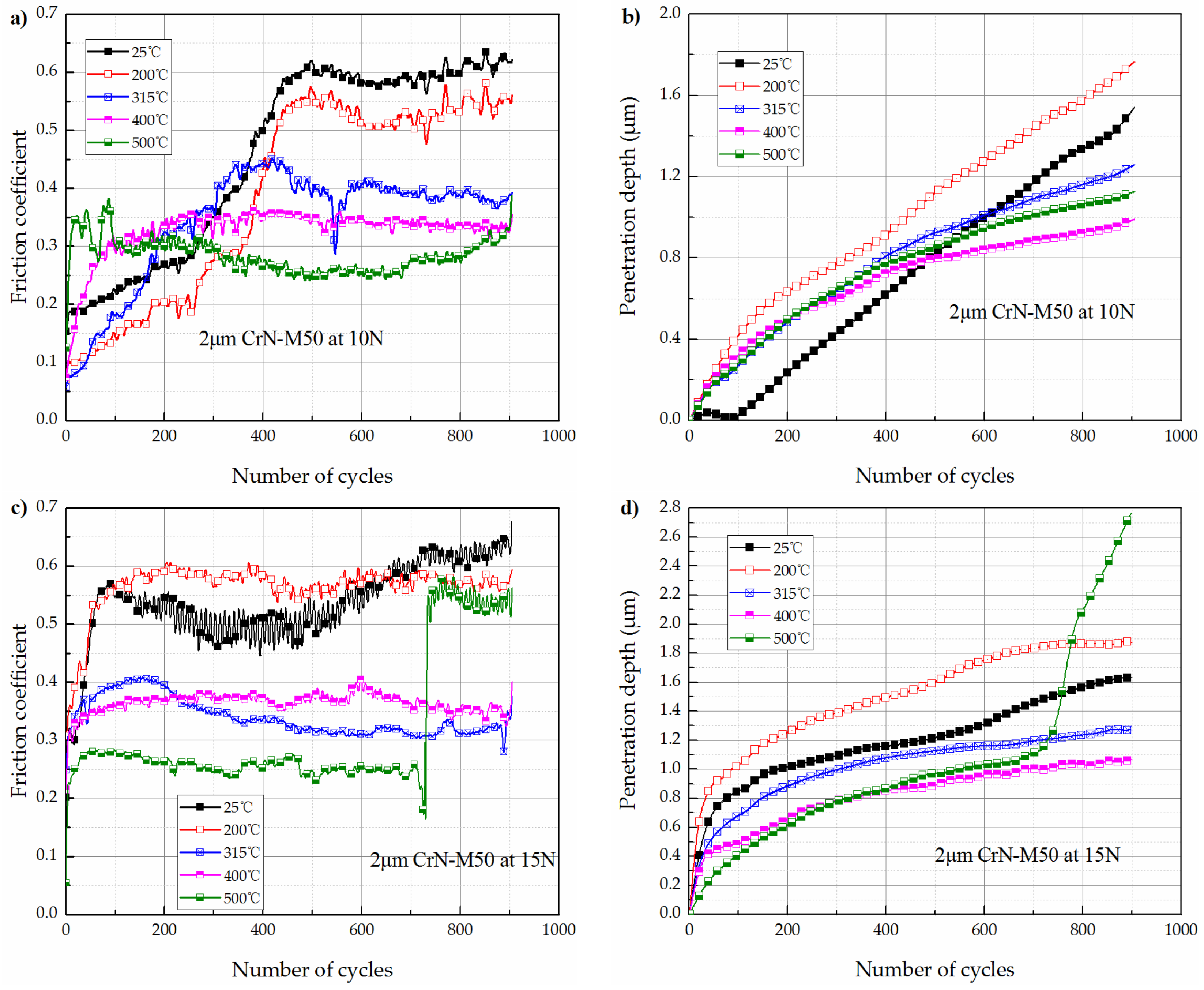
The high temperature tribological response of 2 μm CrN coated M50 disks under each tested loads were quite different from the 5 μm CrN coated M50 disks.
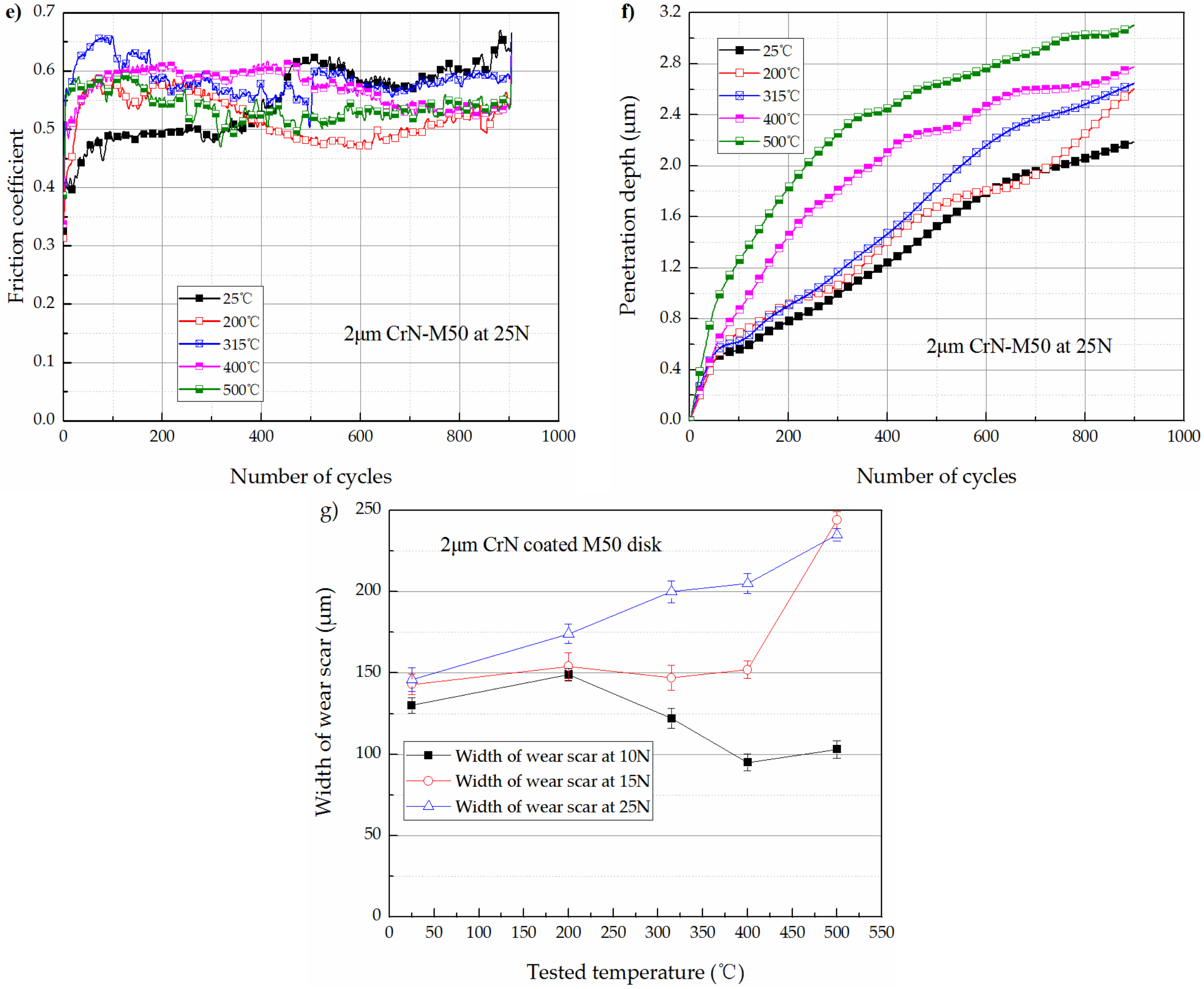
Figure 7a–f shows the friction coefficient curves and penetration depth during wear test of 2 μm CrN coated M50 disks as a function of temperatures under the tested loads of 10 N, 15 N and 25 N. The variation of width of wear scars with temperatures is depicted in
Figure 7g.
As shown in
Figure 6a and
Figure 7a, under the tested load of 10 N, the stable values of friction coefficients of 2 μm CrN coated M50 samples were similar to those of the 5 μm CrN coated M50 samples at each tested temperatures. As shown in
Figure 7c, under the applied load of 15 N, the friction coefficients of 2 μm CrN coated M50 samples were still similar to those for the 5 μm CrN coated M50 samples when the tested temperatures were equal or below 400 °C. However, at the tested temperature of 500 °C, the friction coefficient substantially increased from 0.25 to 0.55 during the wear test. As shown in
Figure 7e, under the applied load of 25 N, the values of friction coefficients at each temperatures were all above 0.5. As shown in
Figure 7g, the width of wear scars was found to be always increased with the tested temperatures under the tested load of 25 N.
As shown in
Figure 7b, the variation trends of penetration depth with temperatures of 2 μm CrN coated M50 samples was similar to 5 μm CrN coated ones. As shown in
Figure 7d, when the tested load was increased to 15 N which was above the load bearing capacity of the 2 μm CrN coated M50 disks at 500 °C, the penetration depth substantially increased at about 700 cycles. It should be noted that the friction coefficient was also substantially increased at about 700 cycles. As shown in
Figure 7f, under an applied load of 25 N which exceed the load bearing capacity of the 2 μm CrN coated M50 disks at any tested temperatures, the wear reduction function of chromium oxide tribo-layer failed. It can be observed that the wear rate always increased with temperatures under the load of 25 N for the 2 μm CrN coated M50 disks.
3.3. Morphology and EDS Results of Worn Surfaces
Figure 8 showed the morphology of worn tracks on 5 μm CrN coated M50 disks under various loads at the temperatures of 25 °C and 200 °C. Small pits, narrow grooves parallel to the sliding direction, and wear debris were detected on the worn surfaces. EDS was used to identify the chemical compositions in different zones, and the results are listed in
Table 2.
The EDS analysis results (at.%) revealed that the worn tracks contained primarily Cr and N after 900 cycles of relative sliding at 25 °C or 200 °C. More importantly, a few W were detected in the worn tracks. It can be confirmed that slight material removal occurred for CrN coatings and WC ball during wear testing at 25 °C and 200 °C, indicating that the dominant wear mechanism at these two temperatures was mild abrasive wear.
In addition to the decreasing of friction coefficient, the morphology of worn tracks at the temperatures above 315 °C was also much different from those at the temperatures below 315 °C.
Figure 9 shows the morphology of wear tracks on 5 μm CrN coated M50 disks when the temperatures were equal or above 315 °C. In
Figure 9a, it can be noticed that the worn tracks were quite smooth after sliding at 315 °C for 900 cycles under each tested loads. In
Figure 9b,c, it can be noticed that the worn surfaces were roughened with oxidized clusters. However, small pits, narrow grooves, and wear debris almost disappeared on the worn surfaces. SEM observation of wear tracks confirmed the existence of tribo-layers with lamellae structure over the worn tracks when wear tests on CrN coatings were performed at the temperatures above 315 °C.
EDS analysis results are listed in
Table 3. It can be observed that the O contents approached or surpassed that of N in the worn area after 900 cycles of relative sliding at 315 °C, 400 °C or 500 °C. Meanwhile, the worn area contained primarily Cr and O. This meant that a mass of tribo-oxides formed on worn surfaces. As referred above [
12], the oxidation of PVD CrN coating material started at the temperature around 300 °C. More importantly, a few W were detected in the worn area, indicating that the oxide film can prevent the adhesion between CrN coating and WC ceramic ball and possess self-lubricant function. Thus, the friction coefficient and width of wear scars decreased at 315 °C. It is clear that wear of CrN coating at temperatures equal or above 315 °C was mild oxidative wear.
It can be concluded that, for 5 μm CrN coated M50 disks, the dominant wear mechanism transitioned from mild abrasive wear to mild oxidation wear when the temperatures were above 315 °C.
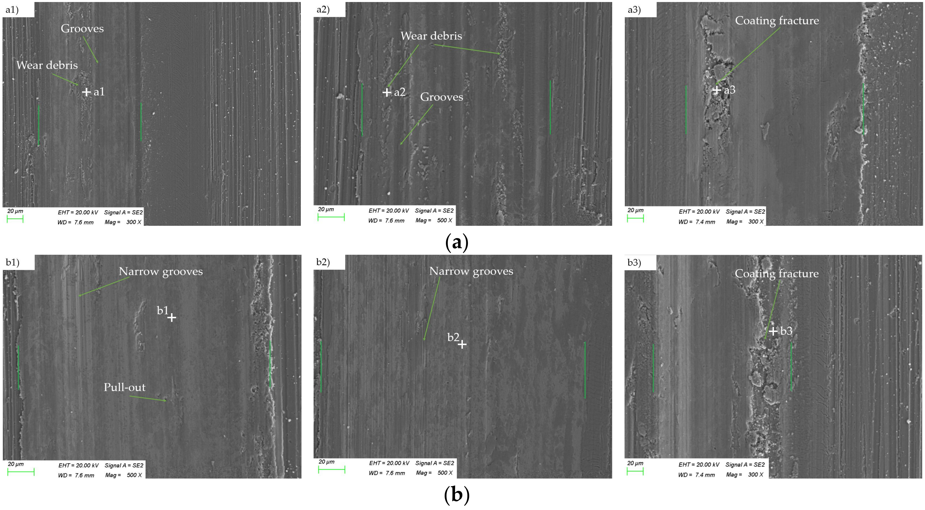
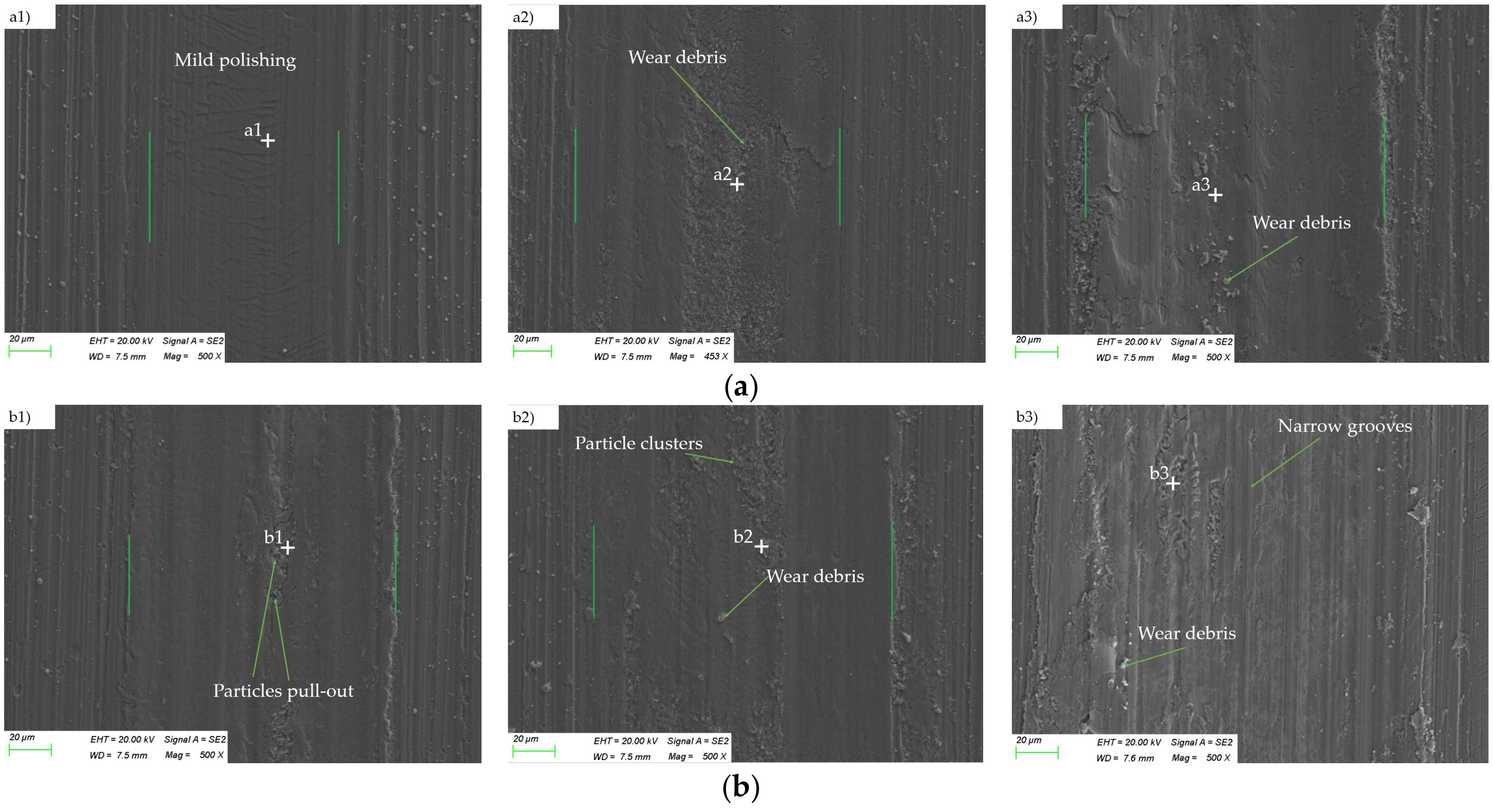
Figure 10 presents the morphology of worn tracks on 2 μm CrN coated M50 disks under various loads at the temperatures of 25 °C and 200 °C. As shown in
Figure 10a1,a2,b1,b2, under the applied load of 10 N or 15 N, the worn tracks on 2 μm CrN coated M50 disks and the worn tracks on 5 μm CrN coated M50 disks presented similar morphology. The dominant wear mechanism for the 2 μm CrN coated M50 samples under the applied load of 10 N or 15 N was mild abrasive wear, corresponding to smooth worn surfaces with wear debris and narrow grooves presented in the worn area. However, when the load was increased to 25 N, local coating fracture can be observed on the edge of the wear scars for the 2 μm CrN coated M50 disks, as illustrated in
Figure 10a3,b3. EDS analysis results are listed in
Table 4. EDS analysis of the coating delamination area (Points a3, b3) confirmed the significant increasing of Fe element, indicating the partial detachment of coating material. The results above indicated that, at lower tested temperatures, the wear of CrN coatings transitioned from mild abrasive wear to the coating fracture controlled wear when the applied load exceeded its the load carrying capacity.
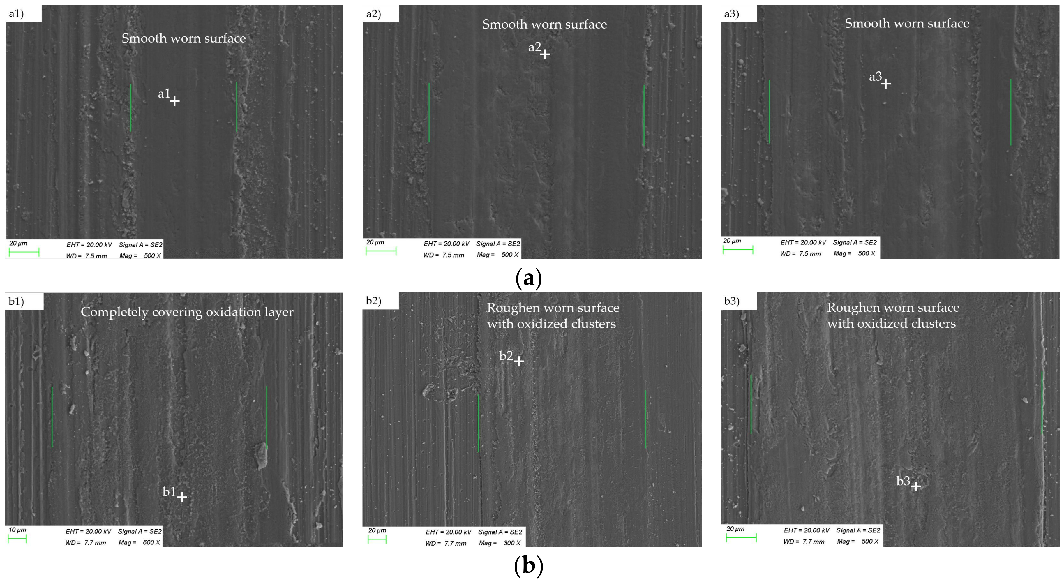
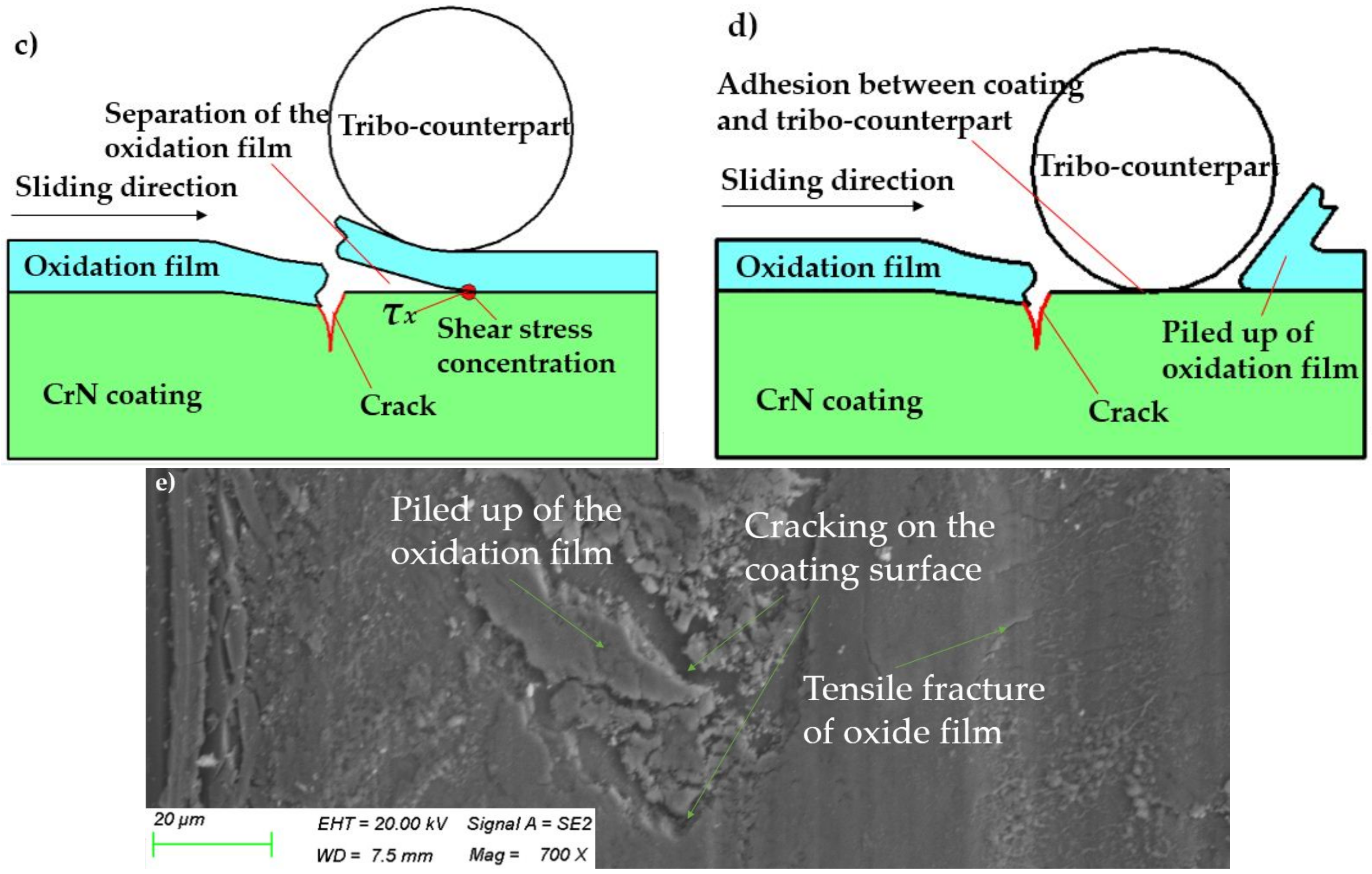
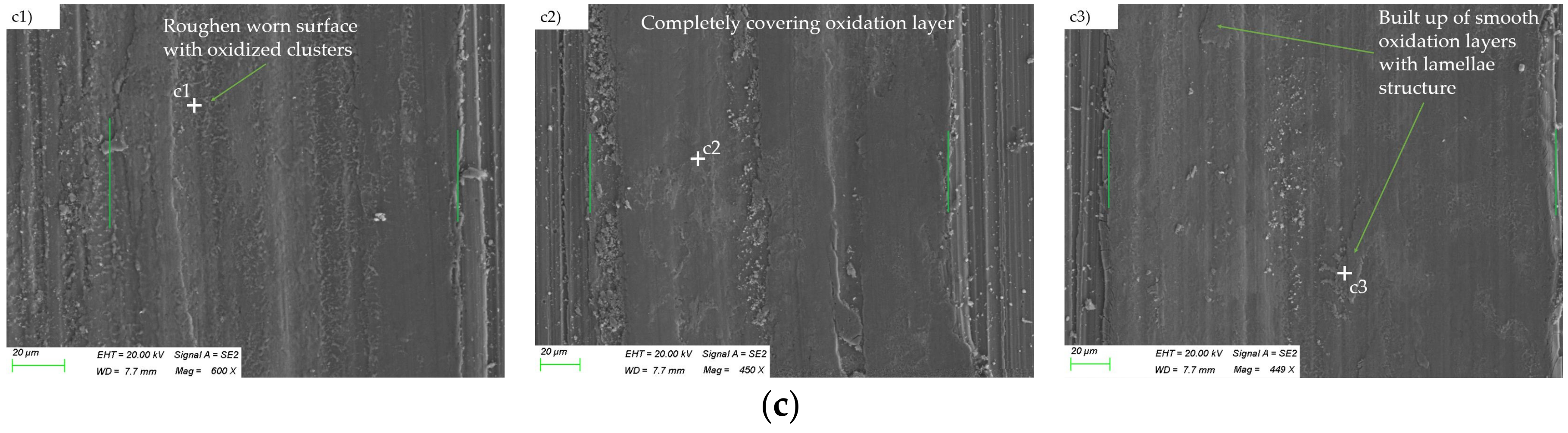
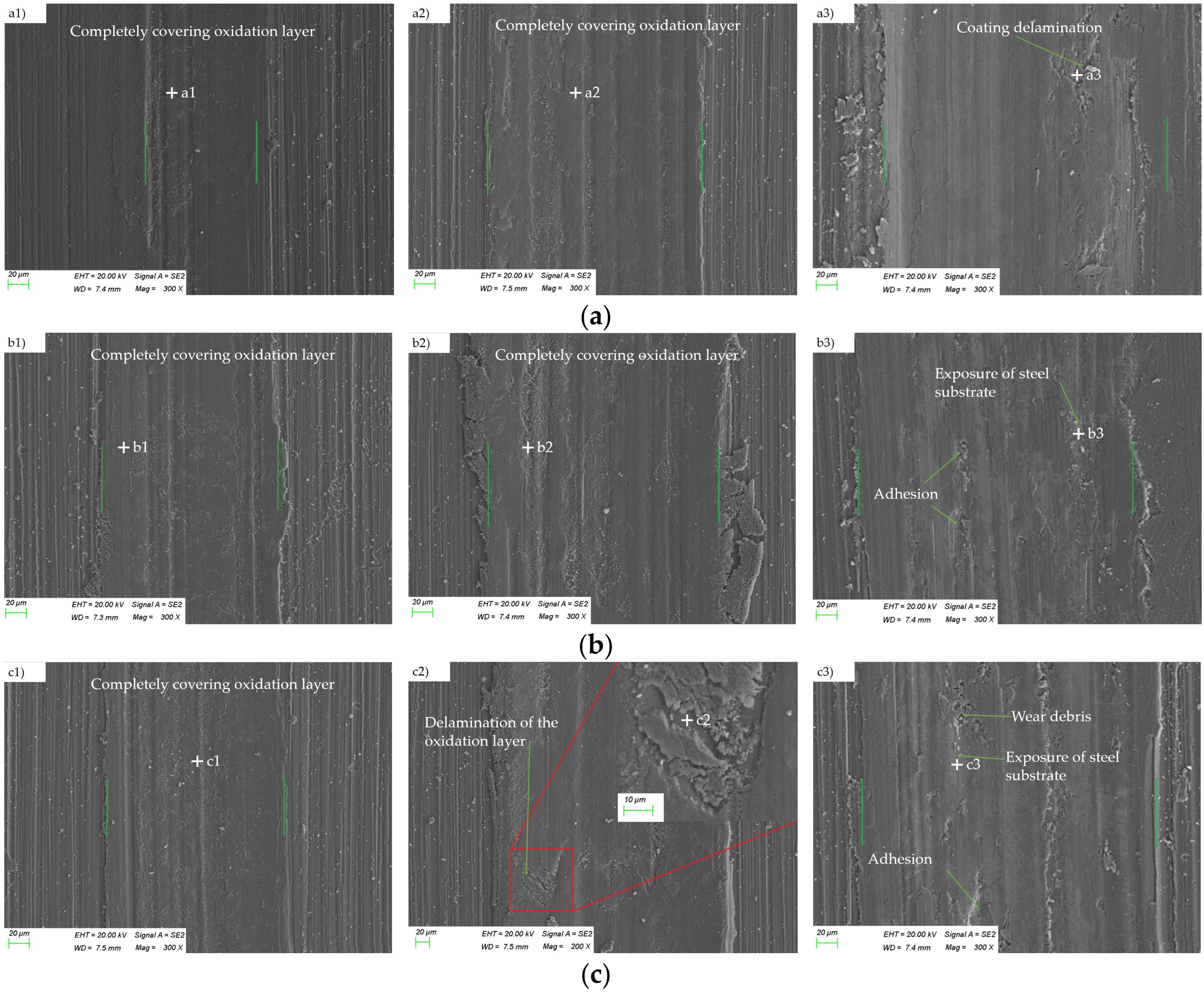
Figure 11 shows the morphology of worn tracks on 2 μm CrN coated M50 disks when the tested temperatures were equal or above 315 °C. As shown in
Figure 11a1,b1,c1, under a tested load of 10 N, the dominant wear mechanism for the 2 μm CrN coated M50 samples was mild-oxidation wear when the tested temperatures were above 315 °C. In additional, under a tested load of 15 N, the wear of 2 μm CrN coated M50 samples could still be characterized as mild-oxidation wear at the temperature of 315 °C and 400 °C, as illustrated in
Figure 11a2,b2. However, when the tested temperature was elevated to 500 °C, the oxidation layers were stripped from the surface of coating under the applied load of 15 N, as illustrated in
Figure 11c2. It should be pointed out that the external load of 15 N just exceeded the load-bearing limitation of 2 μm CrN coated M50 disk at the temperature of 500 °C, as shown in
Figure 5c,d. While the tested load was increased to 25 N, no obvious oxidation layers were detected after wear tests at temperatures of 315 °C, 400 °C and 500 °C, as illustrated in
Figure 11c3,d3,e3.
EDS analysis results are listed in
Table 5. EDS analysis of Points a3, b3, and c3 revealed that the contents of Fe, O significantly surpassed that of Cr, N in the worn area after 900 cycles of relative sliding under the load of 25 N at 315 °C, 400 °C or 500 °C. This indicated the severe materials removal occurred for CrN coatings, thereby leading to exposure of M50 substrate. Besides, it can be noticed that there were delaminated regions and oxidation clusters in a widespread dispersion on the worn tracks. It can be conclude that, at higher tested temperatures, the wear of CrN coated M50 steel transitioned from mild oxidation wear to the compound wear mechanisms containing oxidative wear, coating delamination or adhesive wear when the external load exceeded its load bearing capacities. This was also the key reason why the high temperature friction coefficient of the 2 μm CrN coated M50 samples suddenly increased under the tested load of 25 N.


