Tailoring Characteristics of PEDOT:PSS Coated on Glass and Plastics by Ultrasonic Substrate Vibration Post Treatment


Abstract
:1. Introduction
2. Materials and Methods
2.1. Experimental
2.2. Characterizations
3. Results and Discussion
4. Conclusions
Supplementary Materials
Author Contributions
Funding
Conflicts of Interest
References
- Eslamian, M. Inorganic and organic solution-processed thin film devices. Nano-Micro Lett. 2017, 9, 3. [Google Scholar] [CrossRef]
- Skotheim, T.A.; Reynolds, J. Conjugated Polymers: Theory, Synthesis, Properties, and Characterization; CRC Press: Boca Raton, FL, USA, 2006. [Google Scholar]
- Das, T.K.; Prusty, S. Review on conducting polymers and their applications. Polym. Plast. Technol. Eng. 2012, 51, 1487–1500. [Google Scholar] [CrossRef]
- Shirakawa, H.; Louis, E.J.; MacDiarmid, A.G.; Chiang, C.K.; Heeger, A.J. Synthesis of electrically conducting organic polymers: Halogen derivatives of polyacetylene,(CH)x. J. Chem. Soci. Chem. Commun. 1977, 16, 578–580. [Google Scholar] [CrossRef]
- Sun, K.; Zhang, S.; Li, P.; Xia, Y.; Zhang, X.; Du, D.; Isikgor, F.H.; Ouyang, J. Review on application of PEDOTs and PEDOT: PSS in energy conversion and storage devices. J. Mater. Sci. Mater. Electron. 2015, 26, 4438–4462. [Google Scholar] [CrossRef]
- Groenendaal, L.; Jonas, F.; Freitag, D.; Pielartzik, H.; Reynolds, J.R. Poly(3,4-ethylenedioxythiophene) and its derivatives: Past, present, and future. Adv. Mater. 2000, 12, 481–494. [Google Scholar] [CrossRef]
- Weickert, J.; Sun, H.; Palumbiny, C.; Hesse, H.C.; Schmidt-Mende, L. Spray-deposited PEDOT:PSS for inverted organic solar cells. Sol. Energy Mater. Sol. Cells 2010, 94, 2371–2374. [Google Scholar] [CrossRef] [Green Version]
- Kim, Y.; Lee, J.; Kang, H.; Kim, G.; Kim, N.; Lee, K. Controlled electro-spray deposition of highly conductive PEDOT: PSS films. Sol. Energy Mater. Sol. Cells 2012, 98, 39–45. [Google Scholar] [CrossRef]
- You, J.; Dou, L.; Hong, Z.; Li, G.; Yang, Y. Recent trends in polymer tandem solar cells research. Prog. Polym. Sci. 2013, 38, 1909–1928. [Google Scholar] [CrossRef]
- Duraisamy, N.; Muhammad, N.M.; Ali, A.; Jo, J.; Choi, K.-H. Characterization of poly(3,4-ethylenedioxythiophene):poly(styrenesulfonate) thin film deposited through electrohydrodynamic atomization technique. Mater. Lett. 2012, 83, 80–83. [Google Scholar] [CrossRef]
- Lang, U.; Müller, E.; Naujoks, N.; Dual, J. Microscopical investigations of PEDOT:PSS thin films. Adv. Funct. Mater. 2009, 19, 1215–1220. [Google Scholar] [CrossRef]
- Jönsson, S.; Birgerson, J.; Crispin, X.; Greczynski, G.; Osikowicz, W.; Van Der Gon, A.D.; Salaneck, W.R.; Fahlman, M. The effects of solvents on the morphology and sheet resistance in poly(3,4-ethylenedioxythiophene)–polystyrenesulfonic acid (PEDOT–PSS) films. Synth. Met. 2003, 139, 1–10. [Google Scholar] [CrossRef]
- Medford, A.J.; Lilliedal, M.R.; Jørgensen, M.; Aarø, D.; Pakalski, H.; Fyenbo, J.; Krebs, F.C. Grid-connected polymer solar panels: Initial considerations of cost, lifetime, and practicality. Opt. Express 2010, 18, A272–A285. [Google Scholar] [CrossRef] [PubMed]
- Krebs, F.C.; Gevorgyan, S.A.; Alstrup, J. A roll-to-roll process to flexible polymer solar cells: Model studies, manufacture and operational stability studies. J. Mater. Chem. 2009, 19, 5442–5451. [Google Scholar] [CrossRef]
- Krebs, F.C.; Tromholt, T.; Jørgensen, M. Upscaling of polymer solar cell fabrication using full roll-to-roll processing. Nanoscale 2010, 2, 873–886. [Google Scholar] [CrossRef] [PubMed]
- Kirchmeyer, S.; Reuter, K. Scientific importance, properties and growing applications of poly(3,4-ethylenedioxythiophene). J. Mater. Chem. 2005, 15, 2077–2088. [Google Scholar] [CrossRef]
- Kemerink, M.; Timpanaro, S.; De Kok, M.; Meulenkamp, E.; Touwslager, F. Three-dimensional inhomogeneities in PEDOT: PSS films. J. Phys. Chem. B 2004, 108, 18820–18825. [Google Scholar] [CrossRef]
- Xia, Y.; Ouyang, J. PEDOT: PSS films with significantly enhanced conductivities induced by preferential solvation with cosolvents and their application in polymer photovoltaic cells. J. Mater. Chem. 2011, 21, 4927–4936. [Google Scholar] [CrossRef]
- Cho, S.; Lee, K. Heat-treatment-induced enhancement in the optical spectra of poly(3,4-ethylenedioxythiophene)/poly(stylenesulfonate) films. J. Korean Phys. Soc. 2005, 46, 973–976. [Google Scholar]
- Schmidt, M.; Falco, A.; Loch, M.; Lugli, P.; Scarpa, G. Spray coated indium-tin-oxide-free organic photodiodes with PEDOT: PSS anodes. AIP Adv. 2014, 4, 107132. [Google Scholar] [CrossRef]
- Tait, J.G.; Worfolk, B.J.; Maloney, S.A.; Hauger, T.C.; Elias, A.L.; Buriak, J.M.; Harris, K.D. Spray coated high-conductivity PEDOT: PSS transparent electrodes for stretchable and mechanically robust organic solar cells. Sol. Energy Mater. Sol. Cells 2013, 110, 98–106. [Google Scholar] [CrossRef]
- Cho, C.-K.; Hwang, W.-J.; Eun, K.; Choa, S.-H.; Na, S.-I.; Kim, H.-K. Mechanical flexibility of transparent PEDOT:PSS electrodes prepared by gravure printing for flexible organic solar cells. Sol. Energy Mater. Sol. Cells 2011, 95, 3269–3275. [Google Scholar] [CrossRef]
- Zabihi, F.; Xie, Y.; Gao, S.; Eslamian, M. Morphology, conductivity, and wetting characteristics of PEDOT:PSS thin films deposited by spin and spray coating. Appl. Surf. Sci. 2015, 338, 163–177. [Google Scholar] [CrossRef]
- Eslamian, M.; Newton, J.E. Spray-on PEDOT:PSS and P3HT:PCBM thin films for polymer solar cells. Coatings 2014, 4, 85–97. [Google Scholar] [CrossRef]
- Krebs, F.C. Fabrication and processing of polymer solar cells: A review of printing and coating techniques. Sol. Energy Mater. Sol. Cells 2009, 93, 394–412. [Google Scholar] [CrossRef]
- Kim, J.; Jung, J.; Lee, D.; Joo, J. Enhancement of electrical conductivity of poly(3,4-ethylenedioxythiophene)/poly(4-styrenesulfonate) by a change of solvents. Synth. Met. 2002, 126, 311–316. [Google Scholar] [CrossRef]
- Ouyang, J.; Chu, C.W.; Chen, F.C.; Xu, Q.; Yang, Y. High-conductivity poly(3,4-ethylenedioxythiophene):Poly(styrene sulfonate) film and its application in polymer optoelectronic devices. Adv. Funct. Mater. 2005, 15, 203–208. [Google Scholar] [CrossRef]
- Nardes, A.M.; Janssen, R.A.; Kemerink, M. A morphological model for the solvent-enhanced conductivity of PEDOT: PSS thin films. Adv. Funct. Mater. 2008, 18, 865–871. [Google Scholar] [CrossRef]
- Hu, Z.; Zhang, J.; Hao, Z.; Zhao, Y. Influence of doped PEDOT:PSS on the performance of polymer solar cells. Sol. Energy Mater. Sol. Cells 2011, 95, 2763–2767. [Google Scholar] [CrossRef]
- Yu, Z.; Xia, Y.; Du, D.; Ouyang, J. PEDOT: PSS films with metallic conductivity through a treatment with common organic solutions of organic salts and their application as a transparent electrode of polymer solar cells. ACS Appl. Mater. Interfaces 2016, 8, 11629–11638. [Google Scholar] [CrossRef] [PubMed]
- Fan, Z.; Du, D.; Yu, Z.; Li, P.; Xia, Y.; Ouyang, J. Significant enhancement in the thermoelectric properties of PEDOT:PSS films through a treatment with organic solutions of inorganic salts. ACS Appl. Mater. Interfaces 2016, 8, 23204–23211. [Google Scholar] [CrossRef] [PubMed]
- Wang, Q.; Ahmadian-Yazdi, M.-R.; Eslamian, M. Investigation of morphology and physical properties of modified PEDOT:PSS films made via in-situ grafting method. Synth. Met. 2015, 209, 521–527. [Google Scholar] [CrossRef]
- Vosgueritchian, M.; Lipomi, D.J.; Bao, Z. Highly conductive and transparent PEDOT:PSS films with a fluorosurfactant for stretchable and flexible transparent electrodes. Adv. Funct. Mater. 2012, 22, 421–428. [Google Scholar] [CrossRef]
- Döbbelin, M.; Marcilla, R.; Salsamendi, M.; Pozo-Gonzalo, C.; Carrasco, P.M.; Pomposo, J.A.; Mecerreyes, D. Influence of ionic liquids on the electrical conductivity and morphology of PEDOT:PSS films. Chem. Mater. 2007, 19, 2147–2149. [Google Scholar] [CrossRef]
- Murphy, R.J.; Weigandt, K.M.; Uhrig, D.; Alsayed, A.; Badre, C.; Hough, L.; Muthukumar, M. Scattering studies on poly(3,4-ethylenedioxythiophene)–polystyrenesulfonate in the presence of ionic liquids. Macromolecules 2015, 48, 8989–8997. [Google Scholar] [CrossRef]
- Huang, L.; Cheng, X.; Yang, J.; Zhang, L.; Zhou, W.; Xiao, S.; Tan, L.; Chen, L.; Chen, Y. High-performance polymer solar cells realized by regulating the surface properties of PEDOT:PSS interlayer from ionic liquids. ACS Appl. Mater. Interfaces 2016, 8, 27018–27025. [Google Scholar] [CrossRef] [PubMed]
- Badre, C.; Marquant, L.; Alsayed, A.M.; Hough, L.A. Highly conductive poly(3,4-ethylenedioxythiophene):poly(styrenesulfonate) films using 1-ethyl-3-methylimidazolium tetracyanoborate ionic liquid. Adv. Funct. Mater. 2012, 22, 2723–2727. [Google Scholar] [CrossRef]
- Wang, Q.; Xie, Y.; Soltani-Kordshuli, F.; Eslamian, M. Progress in emerging solution-processed thin film solar cells–part I: Polymer solar cells. Renew. Sustain. Energy Rev. 2016, 56, 347–361. [Google Scholar] [CrossRef]
- Mengistie, D.A.; Ibrahem, M.A.; Wang, P.-C.; Chu, C.-W. Highly conductive PEDOT:PSS treated with formic acid for ITO-free polymer solar cells. ACS Appl. Mater. Interfaces 2014, 6, 2292–2299. [Google Scholar] [CrossRef] [PubMed]
- Zabihi, F.; Eslamian, M. Substrate vibration-assisted spray coating (SVASC): Significant improvement in nano-structure, uniformity, and conductivity of PEDOT:PSS thin films for organic solar cells. J. Coat. Technol. Res. 2015, 12, 711–719. [Google Scholar] [CrossRef]
- Wang, Q.; Eslamian, M. Improving uniformity and nanostructure of solution-processed thin films using ultrasonic substrate vibration post treatment (SVPT). Ultrasonics 2016, 67, 55–64. [Google Scholar] [CrossRef] [PubMed]
- Xie, Y.; Zabihi, F.; Eslamian, M. Fabrication of highly reproducible polymer solar cells using ultrasonic substrate vibration posttreatment. J. Photonics Energy 2016, 6, 045502. [Google Scholar] [CrossRef] [Green Version]
- Zabihi, F.; Ahmadian-Yazdi, M.-R.; Eslamian, M. Fundamental study on the fabrication of inverted planar perovskite solar cells using two-step sequential substrate vibration-assisted spray coating (2S-SVASC). Nanoscale Res. Lett. 2016, 11, 71. [Google Scholar] [CrossRef] [PubMed]
- Habibi, M.; Eslamian, M.; Soltani-Kordshuli, F.; Zabihi, F. Controlled wetting/dewetting through substrate vibration-assisted spray coating (SVASC). J. Coat. Technol. Res. 2016, 13, 211–225. [Google Scholar] [CrossRef]
- Soltani-kordshuli, F.; Zabihi, F.; Eslamian, M. Graphene-doped PEDOT:PSS nanocomposite thin films fabricated by conventional and substrate vibration-assisted spray coating (SVASC). Eng. Sci. Technol. Int. J. 2016, 19, 1216–1223. [Google Scholar] [CrossRef]
- Chen, Q.; Zabihi, F.; Eslamian, M. Improved functionality of PEDOT: PSS thin films via graphene doping, fabricated by ultrasonic substrate vibration-assisted spray coating. Synth. Met. 2016, 222, 309–317. [Google Scholar] [CrossRef]
- Eslamian, M. Excitation by acoustic vibration as an effective tool for improving the characteristics of the solution-processed coatings and thin films. Prog. Org. Coat. 2017, 113, 60–73. [Google Scholar] [CrossRef]
- Fang, X.; Fan, Z.; Gu, Y.; Shi, J.; Chen, M.; Chen, X.; Qiu, S.; Zabihi, F.; Eslamian, M.; Chen, Q. A solution processable flexible transparent conductive graphene/PEDOT:PSS film fabricated by spin and blade coating. J. Shanghai Jiao Tong Univ. (Sci.) 2018, 23, 106–111. [Google Scholar] [CrossRef]
- Cheeke, J.D.N. Fundamentals and Applications of Ultrasonic Waves, 2nd ed.; CRC Press: Boca Raton, FL, USA, 2016. [Google Scholar]
- Rahimzadeh, A.; Eslamian, M. On evaporation of thin liquid films subjected to ultrasonic substrate vibration. Int. Commun. Heat Mass Transf. 2017, 83, 15–22. [Google Scholar] [CrossRef]
- Ouyang, J. “Secondary doping” methods to significantly enhance the conductivity of PEDOT:PSS for its application as transparent electrode of optoelectronic devices. Displays 2013, 34, 423–436. [Google Scholar] [CrossRef]
- Greczynski, G.; Kugler, T.; Keil, M.; Osikowicz, W.; Fahlman, M.; Salaneck, W.R. Photoelectron spectroscopy of thin films of PEDOT–PSS conjugated polymer blend: A mini-review and some new results. J. Electron. Spectrosc. Relat. Phenom. 2001, 121, 1–17. [Google Scholar] [CrossRef]
- Hwang, J.; Amy, F.; Kahn, A. Spectroscopic study on sputtered PEDOT·PSS: Role of surface PSS layer. Org. Electron. 2006, 7, 387–396. [Google Scholar] [CrossRef]
- Park, H.; Lee, S.H.; Kim, F.S.; Choi, H.H.; Cheong, I.W.; Kim, J.H. Enhanced thermoelectric properties of PEDOT:PSS nanofilms by a chemical dedoping process. J. Mater. Chem. A 2014, 2, 6532–6539. [Google Scholar] [CrossRef]
- Lazzaroni, R.; Logdlund, M.; Stafstrom, S.; Salaneck, W.R. The poly-3-hegxylthiophene/NOPF6 systems: A photoelectron spectroscopy study of electronic structural changes induced by the charge transfer in the solid state. Chem. Phys. 1990, 93, 4433. [Google Scholar]
- Selvaganesh, S.V.; Mathiyarasu, J.; Phani, K.; Yegnaraman, V. Chemical synthesis of PEDOT–Au nanocomposite. Nanoscale Res. Lett. 2007, 2, 546. [Google Scholar] [CrossRef]
- Ouyang, L.; Wei, B.; Kuo, C.-c.; Pathak, S.; Farrell, B.; Martin, D.C. Enhanced PEDOT adhesion on solid substrates with electrografted P(EDOT-NH2). Sci. Adv. 2017, 3, e1600448. [Google Scholar] [CrossRef] [PubMed]
- Abdelhamid, M.E.; O’Mullane, A.P.; Snook, G.A. Storing energy in plastics: A review on conducting polymers & their role in electrochemical energy storage. Rsc Adv. 2015, 5, 11611–11626. [Google Scholar]
- Duc, C.; Vlandas, A.; Malliaras, G.G.; Senez, V. Wettability of PEDOT:PSS films. Soft Matter 2016, 12, 5146–5153. [Google Scholar] [CrossRef] [PubMed]


| Nominal Frequency (kHz) | Power (W) | Resonance Frequency (kHz) |
|---|---|---|
| 20 | 5 | 300 @ 18.48 |
| 20 a | 517 @18.48 | |
| 25 | 563 @ 18.48 | |
| 50 | 664 @ 18.48 | |
| 40 | 5 | 3.85 @ 41.20 |
| 20 a | 5.78 @ 41.20 | |
| 25 | 6.40 @ 41.20 | |
| 50 | 7.84 @ 41.20 | |
| 68 | 5 | 2.06 @ 38.80 b |
| 20 a | 2.51 @ 38.76 b | |
| 25 | 2.70 @ 38.75 b | |
| 50 | 2.30 @ 38.89 b | |
| 5 | 0.02 @ 68.16 | |
| 20 a | 0.22 @ 68.17 | |
| 25 | 0.31 @ 68.17 | |
| 50 | 0.46 @ 68.18 |
| Frequency (kHz) | On Glass/ITO (°) | On PET/ITO (°) |
|---|---|---|
| Pristine | 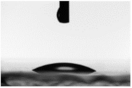 | 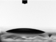 |
| 24.5 ± 3.1 | 22.3 ± 0.6 | |
| 20 | 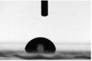 |  |
| 75.9 ± 5.4 | 49.3 ± 0.3 | |
| 40 | 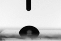 | 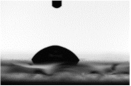 |
| 68.0 ± 3.8 | 51.5 ± 4.5 | |
| 68 |  | 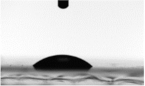 |
| 67.4 ± 4.1 | 43.4 ± 2.0 |
© 2018 by the authors. Licensee MDPI, Basel, Switzerland. This article is an open access article distributed under the terms and conditions of the Creative Commons Attribution (CC BY) license (http://creativecommons.org/licenses/by/4.0/).
Share and Cite
Gholampour, N.; Brian, D.; Eslamian, M. Tailoring Characteristics of PEDOT:PSS Coated on Glass and Plastics by Ultrasonic Substrate Vibration Post Treatment. Coatings 2018, 8, 337. https://doi.org/10.3390/coatings8100337
Gholampour N, Brian D, Eslamian M. Tailoring Characteristics of PEDOT:PSS Coated on Glass and Plastics by Ultrasonic Substrate Vibration Post Treatment. Coatings. 2018; 8(10):337. https://doi.org/10.3390/coatings8100337
Chicago/Turabian StyleGholampour, Nadia, Dominikus Brian, and Morteza Eslamian. 2018. "Tailoring Characteristics of PEDOT:PSS Coated on Glass and Plastics by Ultrasonic Substrate Vibration Post Treatment" Coatings 8, no. 10: 337. https://doi.org/10.3390/coatings8100337