Article

Lightning Performance of Copper-Mesh Clad Composite Panels: Test and Simulation

Key Discipline Laboratory of National Defence for Advanced Technology for Aircraft Design, Nanjing University of Aeronautics & Astronautics, Nanjing 210016, China
*
Author to whom correspondence should be addressed.
Coatings 2019, 9(11), 727; https://doi.org/10.3390/coatings9110727
Submission received: 22 September 2019 / Revised: 27 October 2019 / Accepted: 31 October 2019 / Published: 2 November 2019
(This article belongs to the Special Issue Thin Films for Thermoelectric Applications)

Abstract

:
According to simulation lightning experiments and eddy current analysis results, a three-dimensional finite element model of composite laminated plates with shield is established. By applying electric-thermal boundary and the coupling relationship between them, the lightning strike damage results under the protection of shield are realistically simulated with the commercial finite element analysis software, ABAQUS. Considering the coupling effect of heat, electricity, and force during lightning strike, the load distribution field of copper mesh and carbon fiber panel with lightning current inducted is analyzed. Comparing the thermal stress distribution of the specimen surface under various current loads, it is shown that the stress of carbon fiber panel is significantly lower than the one of the copper screen when the specimen structure suffers heavy current, since the copper network plays a role of endergonic protection. Simulation data are consistent with the test results, thus the method can be used for other similar research.

1. Introduction

The ever-growing demand for lighter structures resulted in the increasing replacement of metal parts by composite structures. Especially in the aeronautic industry, composite materials are expected to increase efficiency without compromising safety. These composite structures are exposed to dynamic damages like aerodynamic loadings, fatigue, low-velocity impact during inspection, and repair [1,2], as well as extreme weather conditions like lightning impact [3,4,5]. This work focuses on the lightning impact response of composite structures.
Traditional aircrafts use aluminum alloy as engineering structure which can fly in bad weather and withstand the strike of lightning. Since aluminum alloy is a very good electrical conductor, severe or catastrophic damages have never been produced when the structure is struck by lightning. In modern aircraft design, however, composite materials are increasingly used in aircraft structure. The most commonly used carbon fiber composite (CFC) is a conductive composite material. Lightning simulations show that unprotected CFC parts can be damaged, and that the material damage is caused by the heating up of the resistance of carbon fiber [6,7,8]. A lightning strike can transmit a large amount of current in a very short time, while it is very difficult for nonmetallic materials to transmit such electric charge. Therefore, the high current causes severe heating, which will cause rapid heating up and evaporation of the composite layer. If this process occurs in limited space, it will result in a considerable pressure, which can reach the extent of structure damage in a large region [9]. Statistically, an aircraft can be struck by the lightning every 3000 flight hours or about once a year [10,11]. Hence, highly efficient lightning strike protection (LSP) methods are a prerequisite for the safety of CFRP-based aircraft with increasing application of CFRP in their exterior structures, such as wings, fuselages, and stabilizers.
As early as in 1946, the lightning institute was established. The nature and mechanism of the lightning phenomenon were studied and the relevant protection methods were discussed [12,13,14,15,16,17]. Hirano et al. [18] studied the damage of composite laminates under different pulse waveform of lightning current and detected the internal damage of laminates by nondestructive testing technology. The results indicated that the Joule heat generated by the lightning current with different impact parameters had a great influence on the failure mode of composite laminates. Kawakami and Firaboli [19] carried out an experimental study and found that the metal net provided a good lightning protection effect with metal mesh laid on the surface of composite laminates. Lightning tests are passed or failed only depending on whether the damage compromises aircraft safety. At high currents, lightning strikes will often do some damage even on structures with protection, which cannot be predicted before testing.
Lightning will have two types of effects on an aircraft: direct and indirect effects. Direct effects include embrittlement or vaporization of resin in the immediate strike area and possible delamination or burn-through of the laminates.
Rajesh et al. [20] studied the damage response of carbon fiber-reinforced polymer (CFRP) panels coated with conducting materials and found that metallic coatings performed better at lightning protection compared to hybrid coatings composed of different materials. Guo et al. [21] investigated the influence of anticorrosion-used fiberglass isolation layer on the lightning strike protection (LSP) of CFRP. Experimental results showed the fiberglass isolation layer enhanced the LSP effectiveness of CFRP, preventing the CFRP from being ablated by internal Joule heat and external heat. Wang et al. [22] reported a percolating-assisted resin film infusion method that achieves a conductive lightning strike protection via the accumulation of reduced graphene oxide on the composite surface. Hirano et al. [23] introduced a developed polyaniline-based conductive thermosetting resin into CFRP structures. Experiments showed that the proposed configuration had higher electric conductivity than that of the conventional epoxy CFRP, indicating a better lightning damage resistance.
However, structural damage on the composite laminates still existed. Aiming at the problem of poor conductivity of composite materials, the copper and aluminum meshes (expanded metal foils) are the mostly adopted LSP solutions for CFRP-based aircraft because of their high conductivity [24,25,26]. Moreover, the metal modified materials, such as Ni-coated carbon nano-tubes (CNTs) [27,28], silver modified buckypaper [29], and metallized carbon fiber veil [30,31] were also developed for LSP. However, metals risk galvanic corrosion when they are in contact with carbon fibers, especially for aluminum [32]. In order to eliminate the galvanic corrosion of metallic LSP materials, an isolation layer is usually recommended to insert between the LSP layer and CFRP substrate, where fiberglass is often preferred. Because fiberglass is electrically insulating, its effect on the elimination of galvanic corrosion is apparent [33,34,35].
Notwithstanding the need for experimental tests, modeling and simulation can provide an understanding of the interaction among the physical phenomena (including mechanical, electromagnetic, and thermal processes) that control the onset and development of damage during lightning impact. Chemartin et al. [36] reported significantly high temperatures for considerably few μs around the arc attachment point for a 100 kA electrical discharge in aluminum skins which were directly responsible for the generation of thermal damage. Ogasawara et al. [37] developed a coupled thermo-electrical damage model for the analysis of angle-ply composite laminates, taking into account the laminate lay-up and anisotropic thermal/electrical behavior of the unidirectional composite layers. Dong et al. [38] performed the composite electrical-thermal-pyrolytic correlation analysis. They further found the lightning strike damage could be estimated by temperature and pyrolysis degree and the contour of the pyrolysis degree is inherited from the contour of temperature [39]. Dhanya and Sekher [40] studied the effects of copper mesh thickness and hole area percentage on the lightning protection of CFRP structures, and an optimal parameter distribution was given. Espejel and Khodaei [41] studied the influence of nanofillers in composite materials on the lightning strike resistance in comparison to the traditional methods. It is concluded that inserting CNTs in the top layer of the composite can improve its lightning strike protection noticeably [41].
Therefore, in the stated literature, thermal/electrical behavior of LSP was obtained by the independent resolution of mechanical and thermo/electrical models by using the finite element method (e.g., implicit and explicit) and neglecting any coupling effects. It is worth noting that most authors have not concerned the damage patterns in the composites and metal mesh in coupling analysis. In this paper, damage and failure are particularly studied through simulation and tests. This provides more information to designers in the preliminary design of copper covered composite LSP structures. In order to explore the protective effect of metallic shielding holistically, coupling simulation method is conducted to analyze the damage caused by lightning impact on composite laminates. Mechanical, thermal, and electrical properties are simultaneously considered. According to the obtained temperature distribution and analytical results, the thermal stress analysis of the laminate is carried out, and the damage process of the laminate in the lightning strike is simulated. The variation and distribution of thermal stress in the laminate during the lightning strike are studied. Meanwhile, lightning and eddy current tests with various impact load are also conducted to validate the proposed simulation scheme.

2. Multi-Field Coupling Simulation Analysis

2.1. Finite Element Method (FEM) Formulation

When the current flows through the conductor, it generates heat. Then the dissipated energy is converted into heat, i.e., Joule heat. When the composite is struck by lightning, the formation of the damage is always accompanied with the coupling of three elements: electricity, heat, and force. According to the law of conservation of charge based on the Maxwell equation, the basic formula of electrical analysis can be derived as
δ ϕ · ( σ · ϕ )   d V = v δ ϕ r e d V + s δ ϕ J ¯ d S
where V is the volume of the control body on the curved surface. δ ϕ is a random variable electric potential field. S, J is the current (surface) density, r e is the internal current source of unit volume, and σ represents conductivity, respectively.
When the lightning current flows through a conductor, the energy dissipated by the resistance of the material increases the temperature of the composite material and causes it to be heated and expanded. Assuming that all electrical energy is converted into thermal energy, the basic formula for heat conduction can be derived as
v ρ C v θ t δ θ d V + v δ θ · ( κ · θ )   d V = v δ θ r d V + s δ θ q d S
where ρ , C v , θ , κ and q represent density, specific heat, temperature, thermal conductivity, and the heat flux density of the flow to the control volume V, respectively.
Due to the anisotropic conductivity and thermal conductivity of composite material, the distributions of temperature and heat are inhomogeneous, resulting in the anisotropic thermal stress field. By coupling the electrical and thermal basic equations above through the conductivity δ = δ ( θ ) and thermal density r = r ( J ) , the potentials, currents, Joule heat, and temperature of each unit can be obtained by calculating these two equations, so as to obtain the thermal stress of each element. Based on the above calculation method, ABAQUS 6.13 simulation software can be used to simulate the damage process of composite materials under lightning strikes.
As shown in Figure 1, the finite element model is a 300 mm × 300 mm × 65 mm rectangular solid, and it contains four layers along the thickness direction: (1) copper screen (the top layer), and the electric resistivity of copper is set as 0.0172 µΩm, (2) carbon fiber top panel, and the thickness of CFRP laminate is 4 mm, (3) honeycomb sandwich structure, of which the thickness is 60 mm, and (4) carbon fiber bottom panel, which is same to the top CFRP panel. The fiber composite material layer is the high temperature curing standard carbon fiber epoxy resin prepreg (CYCOM 970/PWC), the lay-up type of the CFRP panel is [45/0/-45/90]s. The mechanical, thermal, and electrical properties of the applied materials at 25 °C are shown in Table 1 and Table 2. The cohesive contact between the copper mesh layer of the model, when damage arose in copper screen and the CFRP panel to considered, the defined contact start to get failure and the loads couldn’t transfer, so the interlaminar debonding can be simulated by this method. The top panel of the carbon fiber is defined to simulate the bonding interface and release the local degree of freedom. In ABAQUS 6.13, the C3D8 element is used. The boundary conditions and loads on the model are applied as follows. The voltage boundary is set at the four sides of the copper net layer and the initial potential is 0. On the surface of the panel, in contact with the test bench and thus fix constraint is set up, as shown in Figure 2. The temperature boundary is set at the initial temperature of 25 °C. The temperature-dependent mechanical, thermal, and electrical properties of applied materials are illustrated in Table 3, Table 4 and Table 5 [24,40,42,43,44,45,46,47,48].
The current load is applied to the center point on the surface of the model, which is exactly the same as that in tests. The lightning excitation is introduced using electric potential difference. The electric potential on the LSP structure is initially set to zero. The excitations are applied in the center point on the top surface as the same as that in experiments. In view of the short duration of the lightning, the initial step size of the coupling analysis step is set to 0.01 μs, where the minimum step size is 0.0001 μs and the maximum step size is 1 μs. The length of the entire simulation process is equal to the duration of the applied excitation current.

2.2. Numerical Results

Multi-field coupled stress nephograms are shown in Figure 3, Figure 4 and Figure 5. When 100 kA current is applied, the stress level of the copper net is up to 596.9 MPa, which is higher than the permissible value of the material. Thus, the copper net layer is damaged. The stress distribution shown in Figure 3a has a high stress area of about 100 × 100 mm2. The maximum stress of the carbon fiber panel is 471.3 MPa, as shown in Figure 3b, and is lower than the strength of the material.
When 200 kA current is applied, the stress level of the copper net is up to 1297 MPa, which is higher than the permissible value of the material. Thus, the copper net layer is destroyed, as shown in Figure 4a. The maximum stress of the carbon fiber panel is 780.2 MPa, which is also higher than the allowable value of the material strength. The failure occurs in the stress concentration area. As shown in Figure 4b, the stress distribution of concentration region is centrosymmetric with a shape of a cross.
Due to the inhomogeneous distribution of the temperature field along the thickness direction of the laminate in the lightning strike attachment region, greater residual thermal stress will be inevitably generated along the thickness direction. Therefore, when the laminates are subjected to a large current impact, the residual stress will lead to delamination and warp of the laminate.
After the application of the copper mesh protection, the stress distribution along the thickness direction of the specimen is shown in Figure 5. It indicates that only the top layer of the carbon fiber laminates has a larger stress concentration. The thermal stress caused by lightning current cannot spread to the lower layer, which clearly reveals that the copper net has a decent protective effect.
According to the simulation results, the stress level of the carbon fiber panel under different current loads is significantly lower than that of the copper network. This indicates that the copper network plays a certain energy absorption protection. When the 200 kA current is applied, the stress of the carbon fiber board is higher than the permissible value of the material, which is consistent with the results of the lightning test presented below.

3. Lightning and Eddy Current Tests
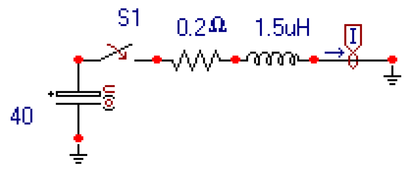
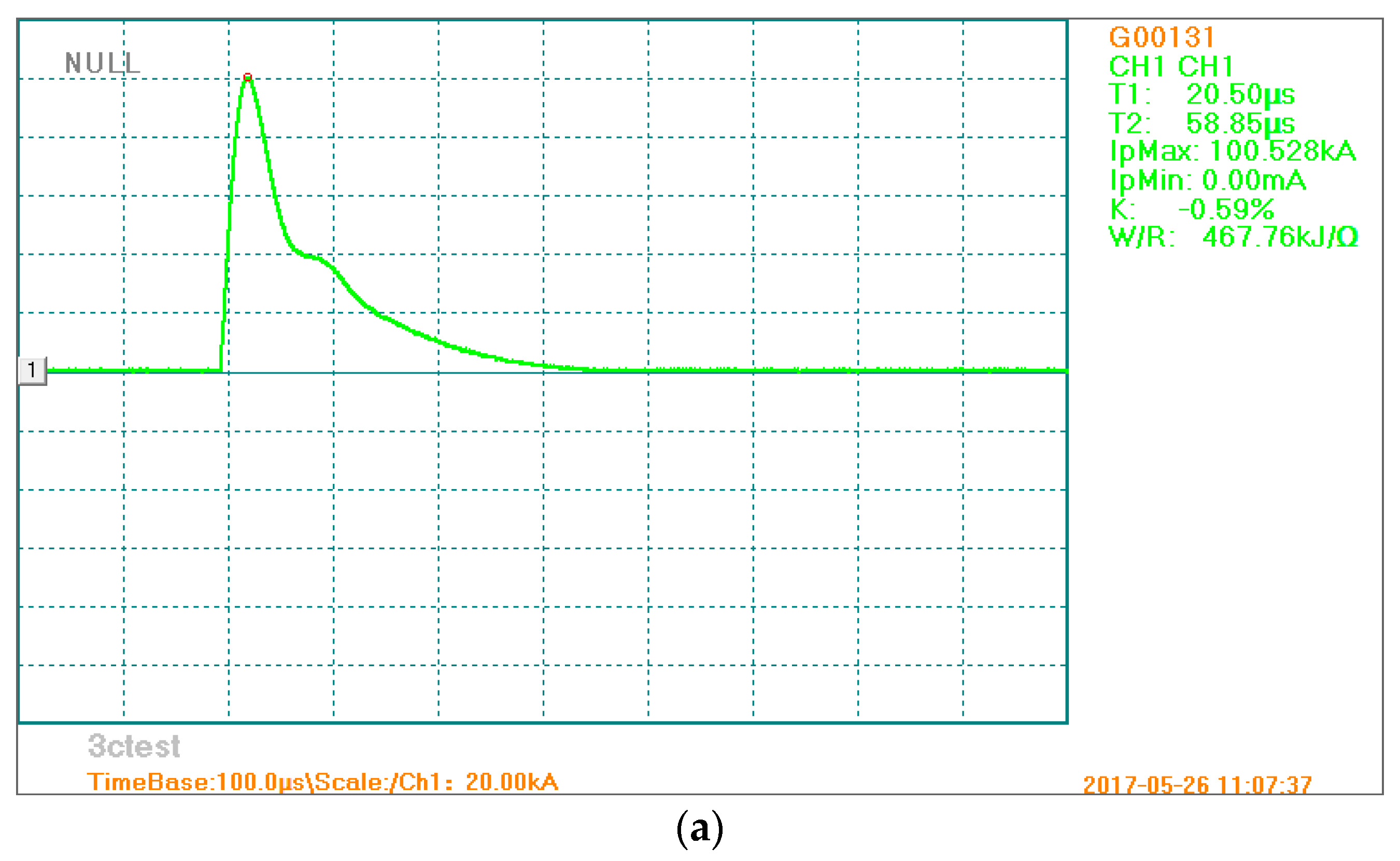
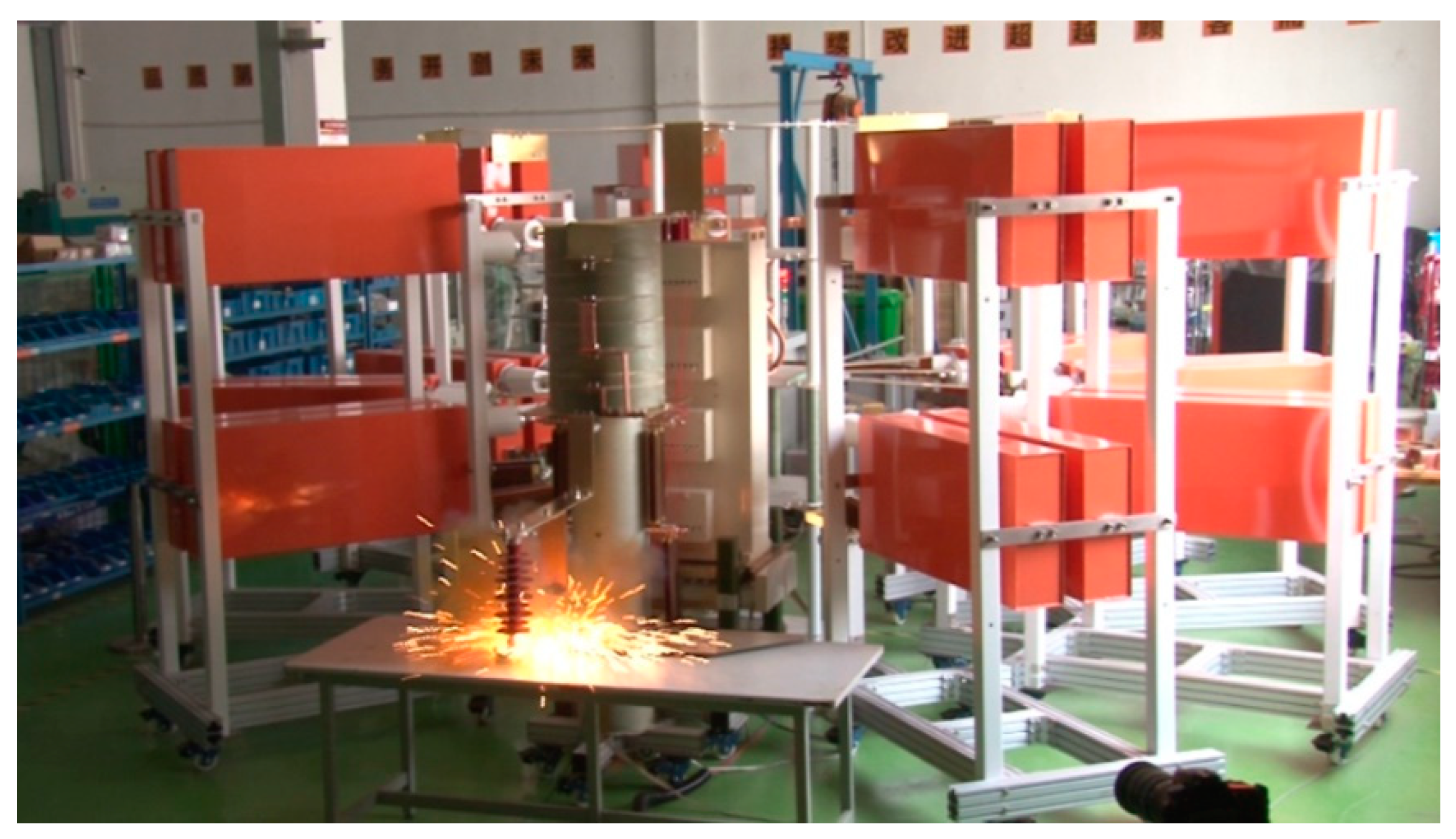
3.1. Test Setup

According to the standard ARP5412 [49], the lighting protection test is conducted. The purpose of this ARP is to provide the characteristics of lightning that are encountered by aircraft as well as transients appearing at the interfaces of equipment associated with electrical/electronic systems as a result of that interaction. These characteristics are referred to as the aircraft lightning environment.
In the lightning protection test, the composite laminates made of high-temperature curing standard carbon fiber epoxy resin prepreg (CYCOM 970/PWC T300 3K) and SynSkinHC9837.1 coating for co-cure bonding. The single layer thickness of the cured laminated plate is 0.216 mm and its area density is 322 g/m2. The schematic of specimen of the lightning protection test are shown in Figure 6. The copper mesh with high conductivity, solidified with the specimen using composite matrix as the adhesive, is used as the lightning shield. This impulse current system contains a LCG300S impulse current generator (3Ctest, Suzhou, China), which is used to generate 300 kA impulse current in 8/20 μs, a MCS2000 fully automatic control system, and an automatic measurement and analysis system. The schematic of impulse current generator illustrated in Figure 7.

3.2. Test Results

The test employed two kinds of current load input, which was 100 and 200 kA, respectively, according to the test standard ARP5412 [49]. The lightning impact currents applied in the tests are shown in Figure 8 in terms of both 100 and 200 kA. In the legend on the right of Figure 8, T1 represents the time of the lightning current reaches the peak from the start of the impact while T2 is the time of the lightning current decays to 50% peak-value from the start of the impact. According to the test standard ARP5412 [49], the ratio of T1/T2 is set to be 1/3. Therefore, for 100 kA, T1 and T2 are 20.5 μs and 58.85 μs, respectively, in the tests. On the other hand, for 200 kA, T1 and T2 are 19.5 μs and 58.75 μs, respectively. IpMax is the peak of lightning current, and IpMin is the minimum of lightning current. For both 100 kA and 200 kA tests, the action time of the lightning impact is 300 μs.
By exerting various current loads to impact the surface of the protected specimen, the metallic net is the first to be impacted by current. After that, the anisotropic thermal stress of the composite layer under electric-thermal coupling leads to material damage. The photograph of lighting protection test is shown in Figure 9. The eddy current inspection based on electromagnetic induction is adopted to observe the damage. By measuring the variation of induced eddy current in the specimen, the material defect can be detected and displayed nondestructively. The principle of eddy current technique is based on the interaction between a magnetic field source and the tested material. One can detect the presence of the defects by sensing changes in the output voltage of the eddy current probe. In eddy current detection system, a transmission-receiver (TR) probe is employed to induce and sense the electromagnetic field, in which the inner diameters, outer diameters, and the height of the coil are 1.2, 3.2, and 0.8 mm, respectively. The input of the probe is provided by an Agilent 33220A and the output is connected to a lock-in amplifier SR-844. The TR probe is controlled by a stepping motor, which is moving on the tested material during the detection process. The output signals are collected by a digitizer, and the acquisition data is processed by a PC-based LabVIEW 2012. Generally, the starting point is located on the intact zone of the material, and zero-calibration of the probe signal should be made by automatically adjusting the output offset before each measurement.
As shown in Figure 10a, the specimen is not damaged by the current impact, and the copper net structure on the surface of the specimen is intact. Figure 10b is the corresponding result of eddy current testing. It shows that the surface of the nondestructive test specimen is a reticular fiber structure. The surface characteristics without current impact are used as the reference of the test.
Under the impact of the 100 kA test current, the visual damage of the specimen is shown in Figure 11a. There is no fiber fracture on the surface, but the structure of copper mesh is obviously damaged. Figure 11b is the result of eddy current testing. It shows that there is no crack defect on the surface of the specimen. Numerical simulation results under 100 kA load show that the stress in composite panel is lower than the strength of the material, consistent with the results of the lightning test.
Under the impact of the 200 kA test current, the visual damage of the specimen is shown in Figure 12a. It is seen that fiber fracture on the surface occurs and the structure of copper mesh is also damaged. Figure 12b is the result of eddy current testing. It indicates that there is considerable crack defect on the surface of the specimen. The fracture fiber was observed, and the center of the specimen is shown as the fracture morphology of the “cross” character, which was consistent with the damage pattern predicted according to surface stress distribution of the simulation result shown in Figure 4b.
The lightning current attached to the surface of the test piece could be conducted simultaneously in the copper mesh and the CFRP laminates. Since the electrical conductivity of the copper mesh is much higher than that of the CFRP laminates, the lightning current is mainly conducted in the copper mesh. Amounts of Joule heat was generated in the panel. After the copper mesh melted in a localized region, the lightning current was completely in contact with the CFRP in the melted zone and is mainly conducted in the composite materials. This generated a large amount of Joule heat in CFRP directly, causing matrix melting, gasification, ablation, and fiber sublimation fracture as shown in Figure 13.

4. Comparison between Simulation and Tests

The results of the lightning test simulation reveal that the copper net shield is damaged under heavy current lightning stroke. It is concluded that the specimen is damaged if the following appearances arisen: (1) Heave in the middle of the specimen, fiber fracture though thickness direction, and pyrolysis in the resin matrix along fiber direction. (2) Delamination near the center of the top surface of specimen, which is along the fiber direction. (3) Multiple ablation-points along the fiber direction. No crack occurs in composite panels under 100 kA current, however, fiber fracture in composite panels can be found on the surface of the protected specimen under 200 kA current. This indicates that copper nets play a protective role, but more effective protective methods are required for higher lightning current.
Furthermore, as can be estimated from Figure 11 and Figure 12, the area damaged due to lightning impacts in experiments is 7850 mm2 and 280 mm2 for 100 kA and 200 kA, respectively. For simulation results, the potential damaged area determined by stress distributions is estimated as 7300 mm2 and 240 mm2 for 100 kA and 200 kA, respectively, as shown in Figure 3 and Figure 4. In comparison, numerical results are consistent well with experimental results in terms of damaged area. It indicates that the proposed numerical formulations can successfully predict potential damaged area of the LSP structure subjected to lightning impact.
On the other hand, it is noted that the results of the eddy current testing reveal that the area damaged for the impact at 100 kA is larger with respect to the area damaged for the impact at 200 kA. It is concluded that the size of damage area is related to the peak value of the lightning current, which can be concluded from the comparison between Figure 11 and Figure 12. The instantaneous discharge power of the 200 kA current is much larger than that of the 100 kA, and the lightning impact was implemented in less than 0.1 ms as it shown in Figure 8. It is shown that lots of electric sparks are releasing during tests as in Figure 9. Along with the damage on the copper mesh in Figure 11 and Figure 12, it is therefore that the tested material was instantly destroyed in the region discharged by the larger impulse current 200 kA, which can be seen in Figure 12a. Meanwhile, the amplitude of the output voltage caused by 200 kA is larger than that caused by 100 kA, which can be seen in Figure 11b and Figure 12b. Moreover, the comparatively smaller discharge power generated by the impulse current with 100 kA is not enough to destroy the material, thus it can only be released inside the material, which caused a large area of damage.

5. Conclusions

The lightning current impact on composite laminates is simulated and analyzed in this paper. The relationship between the material properties and the unit temperature is established, and the thermal and electrical properties of the material is also considered to obtain temperature distribution results of the laminated plate suffered a lightning strike. The results of the eddy current test on the surface of the specimen under two lightning current loads are obtained by simulation and test. Numerical results are consistent with the experimental data. Based on the results reported herein, following conclusions may be drawn.
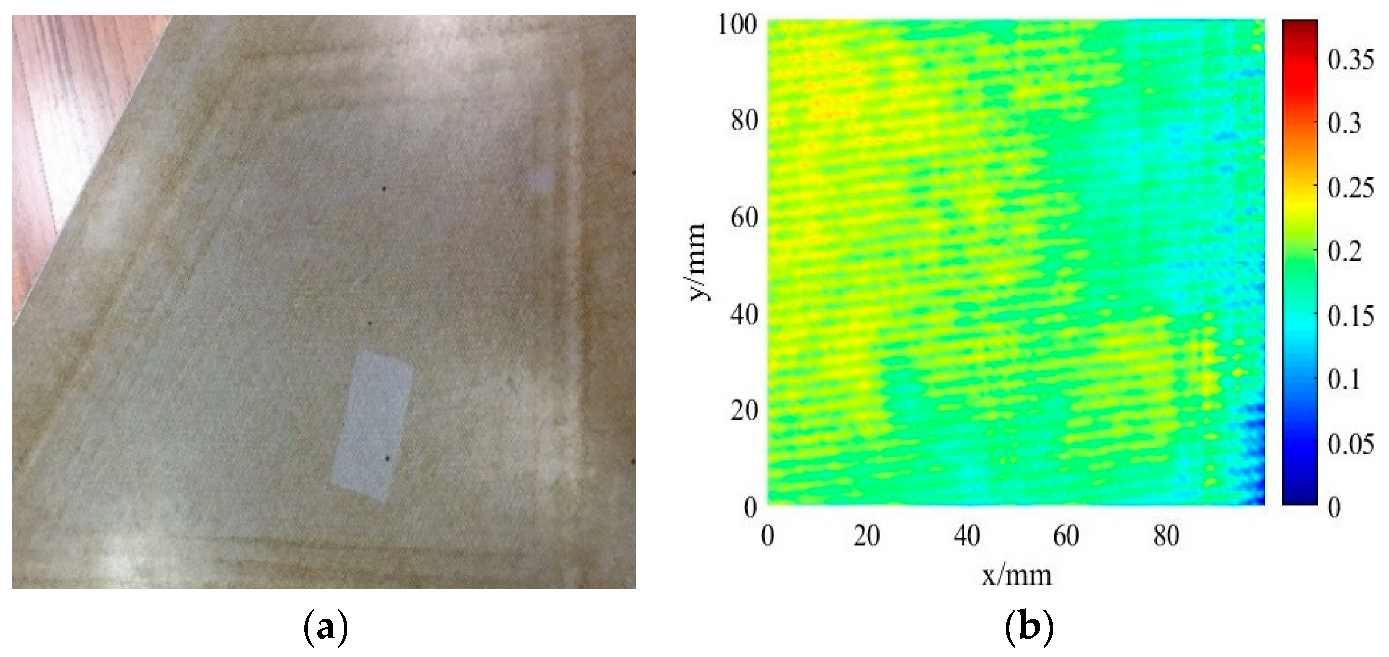
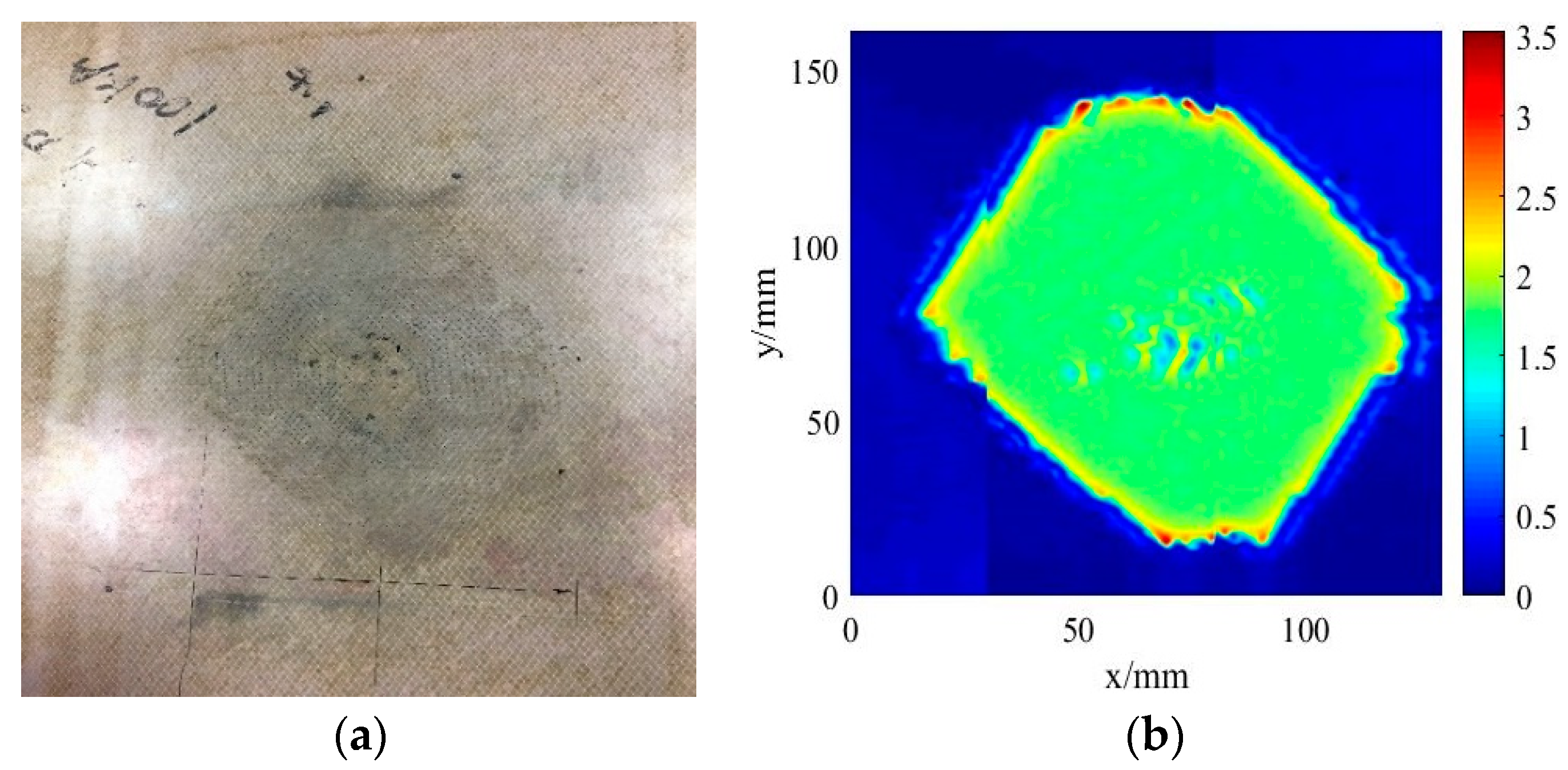
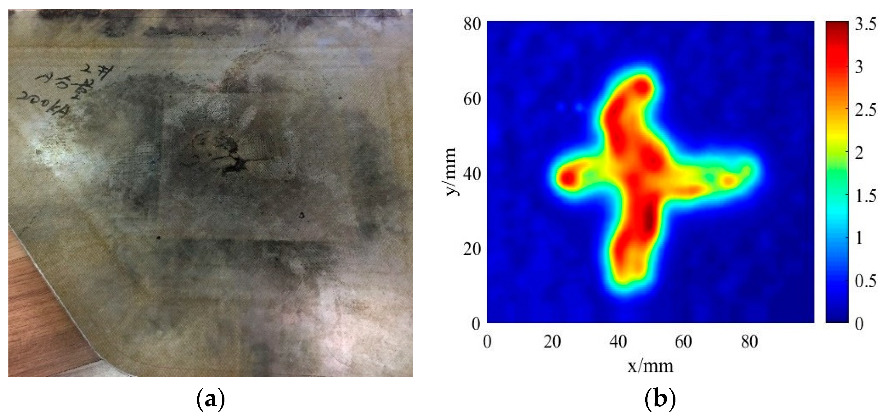
  • Analyzing the stress nephogram of the copper net and carbon fiber panel in the simulation, the lightning damage of the material under the current load of 100 kA and 200 kA can be obtained. By comparing the damage morphology of carbon fiber panel in simulation and lightning test, it is proved that the simulation results are aligned with the experimental data.
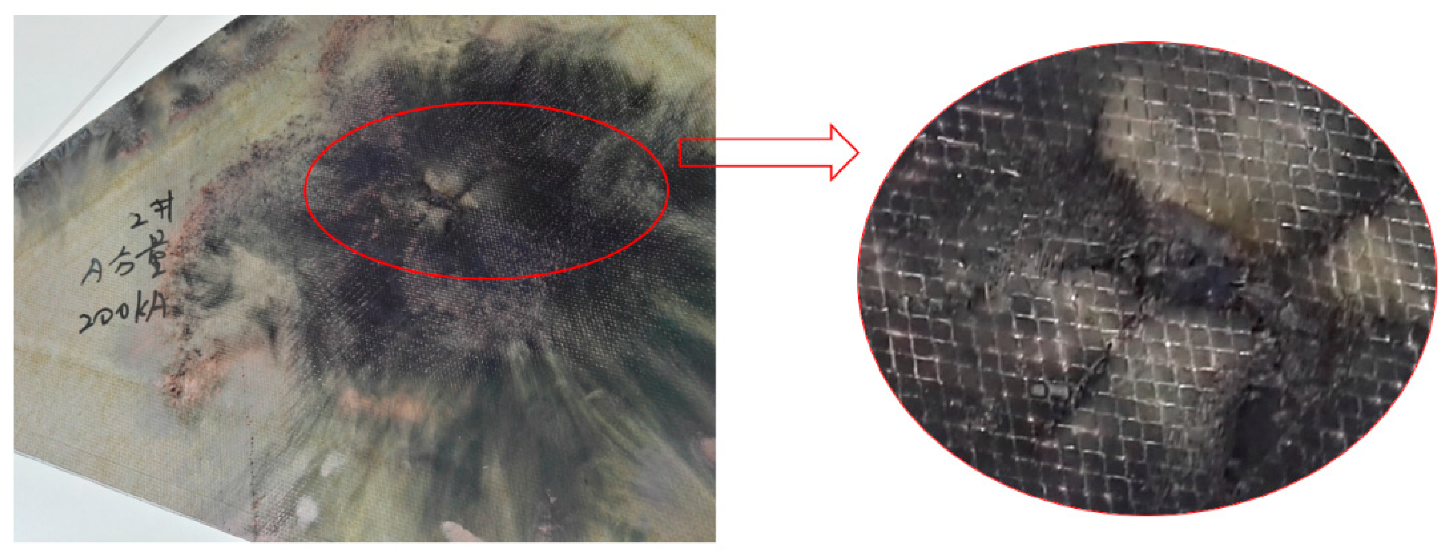
  • Comparing the damage of carbon fiber panel under 100 kA and 200 kA current loads, the protective effect of the copper net is obvious at 100 kA since the panel does not appear fracture damage. However, the panel is damaged along the stress concentration area under 200 kA and the copper mesh is also severely damaged. Therefore, the metal shield has a certain limit in the protective of the lightning strikes.
  • There is no significant residual thermal stress in the direction of the layer thickness, which means that the copper net can play a role of energy absorption protection for the carbon fiber laminates subjected to actual lightning current impact.

Author Contributions

Conceptualization, T.H. and X.Y.; methodology, T.H. and X.Y.; software, T.H.; validation, T.H. and X.Y.; formal analysis, T.H. and X.Y.; investigation, T.H. and X.Y.; resources, H.T.; data curation, H.T.; writing—original draft preparation, H.T.; writing—review and editing, H.T.; visualization, H.T.; supervision, X.Y.; project administration, H.T.; funding acquisition, H.T. please turn to the CRediT taxonomy for the term explanation.

Funding

A Project Funded by the Priority Academic Program Development of Jiangsu Higher Education Institutions (PAPD).

Acknowledgments

Thanks to Suzhou 3CTest for providing experimental equipment.

Conflicts of Interest

The authors declare no conflict of interest.

References

  1. Garcia, C.; Trendafilova, I.; Zucchelli, A. The effect of polycaprolactone nanofibers on the dynamic and impact behavior of glass fibre reinforced polymer composites. J. Compos. Sci. 2018, 2, 43. [Google Scholar] [CrossRef]
  2. Garcia, C.; Trendafilova, I. Triboelectric sensor as a dual system for impact monitoring and prediction of the damage in composite structures. Nano Energy 2019, 60, 527–535. [Google Scholar] [CrossRef] [Green Version]
  3. Gagné, M.; Therriault, D. Lightning strike protection of composites. Prog. Aerosp. Sci. 2014, 64, 1–16. [Google Scholar] [CrossRef]
  4. Patsora, I.; Heuer, H.; Hillmann, S.; Tatarchuk, D. Study of a particle based films cure process by high-frequency eddy current spectroscopy. Coatings 2016, 7, 3. [Google Scholar] [CrossRef]
  5. Katunin, A.; Krukiewicz, K.; Turczyn, R.; Sul, P.; Łasica, A.; Bilewicz, M. Synthesis and characterization of the electrically conductive polymeric composite for lightning strike protection of aircraft structures. Compos. Struct. 2017, 1597, 73–83. [Google Scholar] [CrossRef]
  6. D’amore, M.; Sarto, M.S.; Scarlatti, A. Radiated susceptibility of wiring system aboard lightning struck aircraft. Part I: Sensitivity to the p.u.l. external parameters. In Proceedings of the IEEE International Symposium on Electromagnetic Compatibility, EMC 2002, Minneapolis, MN, USA, 19–23 August 2002; Volume 1, pp. 65–70. [Google Scholar]
  7. Larsson, A. Introduction to aircraft lightning attachment. In Proceedings of the IEEE International Symposium on Electromagnetic Compatibility, EMC 2008, Detroit, MI, USA, 18–22 August 2008; pp. 1–9. [Google Scholar]
  8. Alemour, B.; Badran, O.; Hassan, M.R. A review of using conductive composite materials in solving lightening strike and ice accumulation problems in aviation. J. Aerosp. Technol. Manag. 2019, 11, e1919. [Google Scholar] [CrossRef]
  9. Qiu, G. Lightning protection of aircraft. Environ. Technol. 1985, 2, 21–26. (In Chinese) [Google Scholar]
  10. Uman, M.A.; Rakov, V.A. The interaction of lightning with airborne vehicles. Prog. Aerosp. Sci. 2003, 39, 61–81. [Google Scholar] [CrossRef]
  11. Yin, J.J.; Chang, F.; Li, S.L.; Yao, X.L.; Sun, J.R.; Xiao, Y. Experimental and numerical simulation analysis of typical carbon woven fabric/epoxy laminates subjected to lightning strike. Appl. Compos. Mater. 2017, 24, 1353–1372. [Google Scholar] [CrossRef]
  12. Lauque, P.; Lebey, T.; Mayoux, C.; Guillaumon, J.C. Electrical study of new coating materials for aircraft lightning protection. In Proceedings of the 3rd International Conference on Properties and Applications of Dielectric Materials, IEEE 1991, Tokyo, Japan, 8–12 July 1991; pp. 623–626. [Google Scholar]
  13. Monavon, M.; Leroy, M. Numerical simulation of cruiser or aircraft lightning (Simulation numerique du foudroiement d’un croiseurou d’un avion). Electron. Lett. 1987, 23, 640–642. [Google Scholar] [CrossRef]
  14. He, T.; Sherman, B.D.; Nozari, B.; Rudolph, T. Time domain finite difference validation for transport aircraft lightning induced effect studies. In Proceedings of the 1995 IEEE International Symposium on Electromagnetic Compatibility, Atlanta, GA, USA, 14–18 August 1995; pp. 359–364, Symposium Record. [Google Scholar]
  15. Rao, P.; Shamanna, K.N.; Nagabhushana, G.R. Lightning test facility for light combat aircraft. In Proceedings of the International Conference on Electromagnetic Interference and Compatibility ’99 IEEE, Hyderabad, India, 8 December 1997; pp. 391–394. [Google Scholar]
  16. Ballas, G.; Balanis, C.A. Modeling of lightning effects on simple structures and helicopter airframes using FDTD. In Proceedings of the IEEE Antennas and Propagation Society International Symposium, Orlando, FL, USA, 11–16 July 1999; Volume 1, pp. 598–601. [Google Scholar]
  17. Perrin, E.; Guiffaut, C.; Reineix, A.; Tristant, F. Using a design-of-experiment technique to consider the wire harness load impedances in the FDTD model of an aircraft struck by lightning. IEEE Trans. Electromagn. Compat. 2013, 55, 747–753. [Google Scholar] [CrossRef]
  18. Hirano, Y.; Katsumata, S.; Iwahori, Y.; Todoroki, A. Artificial lightning testing on graphite/epoxy composite laminate. Compos. Part A Appl. Sci. Manuf. 2010, 41, 1461–1470. [Google Scholar] [CrossRef]
  19. Feraboli, P.; Kawakami, H. Damage of carbon/epoxy composite plates subjected to simulated lightning strike. J. Aircr. 2010, 47, 999–1012. [Google Scholar] [CrossRef]
  20. Rajesh, P.S.M.; Sirois, F.; Therriault, D. Damage response of composites coated with conducting materials subjected to emulated lightning strikes. Mater. Des. 2018, 139, 45–55. [Google Scholar] [CrossRef]
  21. Guo, Y.; Xu, Y.; Zhang, L.; Wei, X.; Dong, Q.; Yi, X.; Jia, Y. Implementation of fiberglass in carbon fiber composites as an isolation layer that enhances lightning strike protection. Compos. Sci. Technol. 2019, 174, 117–124. [Google Scholar] [CrossRef]
  22. Wang, B.; Duan, Y.; Xin, Z.; Yao, X.; Abliz, D.; Ziegmann, G. Fabrication of an enriched graphene surface protection of carbon fiber/epoxy composites for lightning strike via a percolating-assisted resin film infusion method. Compos. Sci. Technol. 2018, 158, 51–60. [Google Scholar] [CrossRef]
  23. Hirano, Y.; Yokozeki, T.; Ishida, Y.; Goto, T.; Takahashi, T.; Qian, D.; Ito, S.; Ogasawara, T.; Ishibashi, M. Lightning damage suppression in a carbon fiber-reinforced polymer with a polyaniline-based conductive thermoset matrix. Compos. Sci. Technol. 2016, 127, 1–7. [Google Scholar] [CrossRef]
  24. Abdelal, G.; Murphy, A. Nonlinear numerical modelling of lightning strike effect on composite panels with temperature dependent material properties. Compos. Struct. 2014, 1092, 68–78. [Google Scholar] [CrossRef]
  25. Guo, Y.; Xu, Y.; Wang, Q.; Dong, Q.; Yi, X.; Jia, Y. Eliminating lightning strike damage to carbon fiber composite structures in Zone 2 of aircraft by Ni-coated carbon fiber nonwoven veils. Compos. Sci. Technol. 2019, 169, 95–102. [Google Scholar] [CrossRef]
  26. Morgan, J. Thermal simulation and testing of expanded metal foils used for lightning protection of composite aircraft structures. SAE Int. J. Aerosp. 2013, 6, 371–377. [Google Scholar] [CrossRef]
  27. Black, S. Lightning strike protection strategies for composite aircraft. High Perform. Compos. 2013. [Google Scholar]
  28. Chakravarthi, D.K.; Khabashesku, V.N.; Vaidyanathan, R.; Blaine, J.; Yarlagadda, S.; Roseman, D.; Zeng, Q.; Barrera, E.V. Carbon fiber–bismaleimide composites filled with nickel-coated single-walled carbon nanotubes for lightning-strike protection. Adv. Funct. Mater. 2011, 21, 2527–2533. [Google Scholar] [CrossRef]
  29. Dong, Q.; Wan, G.; Xu, Y.; Guo, Y.; Du, T.; Yi, X.; Jia, Y. Lightning damage of carbon fiber/epoxy laminates with interlayers modified by nickel-coated multi-walled carbon nanotubes. Appl. Compos. Mater. 2017, 24, 1339–1351. [Google Scholar] [CrossRef]
  30. Chu, H.; Xia, Q.; Zhang, Z.; Liu, Y.; Leng, J. Sesame-cookie topography silver nanoparticles modified carbon nanotube paper for enhancing lightning strike protection. Carbon 2019, 143, 204–214. [Google Scholar] [CrossRef]
  31. Ji, C.; Ma, Q.; Wang, Z.; Ji, C.; Ma, Q.; Wang, Z.; Li, N. Design and application of lightning protection layer for aircraft composites. Aerosp. Mater. Technol. 2011, 5, 50–54. (In Chinese) [Google Scholar]
  32. Zhao, Z.J.; Xian, G.J.; Yu, J.G.; Wang, J.; Tong, J.F.; Wei, J.H.; Wang, C.C.; Moreira, P.; Yi, X.S. Development of electrically conductive structural BMI based CFRPs for lightning strike protection. Compos. Sci. Technol. 2018, 167, 555–562. [Google Scholar] [CrossRef]
  33. Feraboli, P.; Miller, M. Damage resistance and tolerance of carbon/epoxy composite coupons subjected to simulated lightning strike. Compos. Part A Appl. Sci. Manuf. 2009, 40, 954–967. [Google Scholar] [CrossRef]
  34. Federal Aviation Administration. AC 20–53—Protection of Airpcraft Fuel Systems against Lightning; Federal Aviation Administration: Washington, DC, USA, 1967.
  35. Zhang, J.Q.; Zhang, J.; Qi, S.J.; Zhang, J.Q.; Zhang, J.; Qi, S.J.; Cheng, X.Q. Numerical simulation of lightning damage of composite laminates. High Tech Fiber Appl. 2014, 39, 36–39. (In Chinese) [Google Scholar]
  36. Chemartin, L.; Lalande, P.; Peyrou, B.; Chazottes, A.; Elias, P.Q.; Delalondre, C.; Cheron, B.G.; Lago, F. Direct Effects of Lightning on Aircraft Structure: Analysis of the Thermal, Electrical and Mechanical Constraints. J. Aeros. Lab. 2012, 5, 1–12. [Google Scholar]
  37. Ogasawara, T.; Hirano, Y.; Yoshimura, A. Coupled thermal–electrical analysis for carbon fiber/epoxy composites exposed to simulated lightning current. Compos. Part A Appl. Sci. Manuf. 2010, 41, 973–981. [Google Scholar] [CrossRef]
  38. Dong, Q.; Guo, Y.; Sun, X.; Jia, Y. Coupled electrical-thermal-pyrolytic analysis of carbon fiber/epoxy composites subjected to lightning strike. Polymer 2015, 56, 385–394. [Google Scholar] [CrossRef]
  39. Dong, Q.; Guo, Y.; Chen, J.; Yao, X.; Yi, X.; Ping, L.; Jia, Y. Influencing factor analysis based on electrical-thermal-pyrolytic simulation of carbon fiber composites lightning damage. Compos. Struct. 2016, 140, 1–10. [Google Scholar] [CrossRef]
  40. Dhanya, T.M.; Yerramalli, C.S. Lightning strike effect on carbon fiber reinforced composites—Effect of copper mesh protection. Mater. Today Commun. 2018, 161, 24–34. [Google Scholar] [CrossRef]
  41. de Toro Espejel, J.F.; Sharif Khodaei, Z. Lightning strike simulation in composite structures. Key Eng. Mater. 2017, 754, 181–184. [Google Scholar] [CrossRef]
  42. Fanucci, J.P. Thermal response of radiantly heated kevlar and graphite/epoxy composites. J. Compos. Mater. 1987, 21, 129–139. [Google Scholar] [CrossRef]
  43. Griffis, C.A.; Nemes, J.A.; Stonesifer, F.R.; Chang, C.I. Degradation in strength of laminated composites subjected to intense heating and mechanical loading. J. Compos. Mater. 1986, 20, 216–235. [Google Scholar] [CrossRef]
  44. Liu, Z.Q. Analysis of Electro-Magneto-Thermo-Structural Coupling Effects on Composite Laminates in Lightning Environment. Ph.D Thesis, Northernwest Polytechnic University, Xi’an, China, December 2015. [Google Scholar]
  45. Lago, F.; Gonzalez, J.J.; Freton, P.; Uhlig, F.; Lucius, N.; Piau, G.P. A numerical modelling of an electric arc and its interaction with the anode: Part III. Application to the interaction of a lightning strike and an aircraft in flight. J. Phys. D Appl. Phys. 2006, 39, 2294. [Google Scholar] [CrossRef]
  46. Zinkle, S.J.; Fabritsiev, S.A. Copper alloys for high heat flux structure applications. In Atomic and Plasma-Material Interaction Data for Fusion (Supplement to Nuclear Fusion); International Atomic Energy Agency: Vienna, Austria, 1994; Volume 5, p. 163. [Google Scholar]
  47. Gathers, G.R. Thermophysical properties of liquid copper and aluminum. Int. J. Thermophys. 1983, 4, 209–226. [Google Scholar] [CrossRef]
  48. White, G.K.; Minges, M.L. Thermophysical properties of some key solids: An update. Int. J. Thermophys. 1997, 18, 1269–1327. [Google Scholar] [CrossRef]
  49. SAE International. Aircraft Lightning Environment and Related Test Waveforms; AE-2 Lightning Committee: New York, NY, USA, 2013. [Google Scholar]
Figure 1. Finite element model diagram.
Coatings 09 00727 g001
Figure 2. Boundary conditions and loading diagrams.
Coatings 09 00727 g002
Figure 3. Stress nephogram of 100 kA multi-field coupling simulation.
Coatings 09 00727 g003
Figure 4. Stress nephogram of 200 kA multi-field coupling simulation.
Coatings 09 00727 g004
Figure 5. Stress nephogram of 100 kA multi-field coupling simulation along the thickness direction.
Coatings 09 00727 g005
Figure 6. Schematic of specimen of lightning protection test.
Coatings 09 00727 g006
Figure 7. LCG300S impulse current generator.
Coatings 09 00727 g007
Figure 8. Lightning impact currents applied in the tests. (a) 100 kA, (b) 200 kA.
Coatings 09 00727 g008aCoatings 09 00727 g008b
Figure 9. Lighting protection test.
Coatings 09 00727 g009
Figure 10. Before test. (a) Undamaged specimen, (b) Eddy current testing.
Coatings 09 00727 g010
Figure 11. 100 kA current test. (a) Impacted specimen, (b) Eddy current testing.
Coatings 09 00727 g011
Figure 12. 200 kA current test. (a) Impacted specimen, (b) Eddy current testing.
Coatings 09 00727 g012
Figure 13. Damage patterns in the copper mesh covered CFRP laminates in the 200 kA lightning current test.
Coatings 09 00727 g013
Table 1. Mechanical properties of applied materials at 25 °C.
MaterialLongitudinal Modulus E1Longitudinal Strength S1Transverse Modulus E2Transverse Strength S2Shear Modulus G12Shear Strength S12Poisson’s Ratio -12 v12
CFRP56.1/GPa650/MPa55.8/GPa630/MPa3.65/GPa100/MPa0.06
Honey-comb3.3/MPa0.98/MPa3.3/MPa1.51/MPa260/MPa2.13/MPa0.59
MaterialElastic ModulusYield StrengthPoisson’s Ratio
Copper119/GPa500/MPa0.33
Table 2. Electrical and thermal properties of applied material at 25 °C.
Material ItemsElectrical Conductivity (S/m)Thermal Conductivity (W/m/°C)Specific Heat Capacity (J/kg/°C)Thermal Expansion Coefficient
CFRPLongitudinal2.89 × 10311.89125 × 10−6
Transverse2.68 × 10311.69125 × 10−6
Through-thickness3.24 × 10210.19124 × 10−5
Copper5.8 × 1074103861.67 × 10−5
Honeycomb2.51 × 1020.2512001.85 × 10−5
Table 3. CYCOM 970/PWC thermal and electrical material properties vs. temperature.
Temperature (°C)Specific Heat (J/kg/°C)Longitudinal Thermal Conductivity (W/m/°C)Transverse Thermal Conductivity (W/m/°C)Through-Thickness Thermal Conductivity (W/m/°C)Longitudinal Electrical Conductivity (S/m)Transverse Electrical Conductivity (S/m)Through-Thickness Electrical Conductivity (S/m)
2591211.811.60.672.89 × 1042.68 × 1047.54
34315006.06.00.182.91 × 1042.72 × 1048.52
50015202.82.40.13.42 × 1042.77 × 10425.4 [24]
52511702.31.90.13.42 × 1042.77 × 10425.4
100011701.41.30.13.42 × 1042.82 × 104 [42,43,44,45]25.4
331611701.41.30.17.43 × 1037.57 × 103 [42,43,44,45]25.4
Table 4. Copper thermal and electrical material properties [24,40,46,47,48].
Temperature (°C)Specific Heat (J/kg/°C)Thermal Conductivity (W/m/°C)Electrical Conductivity (S/m)
253864015.8 × 107
5104313702.0 × 107
5004313394.6 × 106
10004901503.7 × 106
17001802.4 × 106
26002.2 × 106
32271.5 × 106 [40]
7000
7200
8000550 [24]180 [24]1.4 × 10⁶ [46,47,48]
Table 5. CYCOM 970/PWC mechanical properties vs. temperature.
Temperature (°C)E11/GPaE22/GPaG12/GPav12
2556.155.83.650.06
15055.755.63.510.06
20055.755.63.140.06
50055.154.80.250.06
150028.526.40.250.06
200021.2 [44]21.00.240.06
30000.1 [44]0.10.180.06

