Article

Analysis of a Thin Layer Formation of Third-Grade Fluid

1
Energy Research Centre, COMSATS University Islamabad, Lahore 54000, Pakistan
2
Department of Mathematics, COMSATS University Islamabad, Lahore 54000, Pakistan
3
Center for Coal Technology, University of the Punjab, Lahore 54590, Pakistan
4
School of Systems and Technology, University of Management and Technology, Lahore 54000, Pakistan
5
Department of Energy Engineering, Faculty of Mechanical and Aeronautical Engineering, University of Engineering and Technology, Taxila 47050, Pakistan
6
Department of Electronic Engineering, Faculty of Applied Energy System, Jeju National University, JejuSpecial Self-GoverningProvince, Jeju-si 63243, Korea
7
Department of Computer Science, Information Technology University, Lahore 54000, Pakistan
*
Authors to whom correspondence should be addressed.
These authors contributed equally to this work.
Coatings 2019, 9(11), 741; https://doi.org/10.3390/coatings9110741
Submission received: 1 October 2019 / Revised: 4 November 2019 / Accepted: 5 November 2019 / Published: 8 November 2019
(This article belongs to the Section Surface Characterization, Deposition and Modification)

Abstract

:
In present learning, surface protection layer progression of a third-grade fluid (TGF) is examined. Fluid transport within the micro passage made by the firm bladehas beenpresented. Main system of equations of fluidity have been narrated and streamlined by means of lubrication approximation theory (LAT). Here, approximate solutions of velocity, pressure gradient, and coating depth have been presented. Results of coating and layer forming have been tabulated and discussed as well. It is observed that the transport properties of third-order fluid delivers an instrument to regulate flow velocity, pressure, and affect the final coated region.

1. Introduction

Third-grade fluids fit into the category of well-ordered flowing-particles. These have thermo-viscoelastic properties and are amongst the non-Newtonian fluids (NNF) originated from the viscous constituents and elastic materials. Some of their specimens are polymeric-paints, DNA fluids, bio-organic solutions, and other synthetic materials. Polymeric fluids are practically ubiquitously exist and are used as thin layer deposition materials. Although these organic solutions and colloids demonstrate thermo-viscoelastic behavior. For these coating systems, applied stress takes into the mathematical relationship that is not simply existing in a single equation as described in [1,2,3,4,5]. In this work, Carapau et al. [2] based constitutive model for a third-order fluids is presented. In the present order, beta (β) is taken as a third-order type material factor. Phenomenaof shear thickening or shear thinning are largely governed by its mathematical assessment. If material factor beta is larger than zero, the physical system performs similar to a shear thickening substance. In caseswhere thematerial factor beta is a smaller than zero, the physical system acts similar to shear thinning substance.Liquid properties of blade surface protection coatings are mesmerizing, mainly owing to significant engineering solicitations. Application of coating to blade is a progression through which polymeric-particle is coated uninterruptedly to the non-stationery web, and micro-coating thickness is applied on the inflexible part. Blade coatings are largely castoff in broadsheet coats, as it delivers promising evenness to the broadsheets. Other solicitations contain metal oxide based coatings on magnetic recording or adhesive tape, in addition to, suspension glaze on photo layers. Many researchers [2,3,4,5,6,7] investigated coating flows of Newtonian fluids. Most liquids castoff in manufacturing and mechanical applications have non-linear mathematical behaviors between applied pressure and induced deformation. Most of surface protection coatings belong to NNF. Non-Newtonian category liquids are categorized bestowing to their constitutive models. Applied pressure or stress in case of these liquids is a non-linear strain, and proceeding for the answers of these models isnot so straightforward. This is applicable and correct for both exact and for approximate results. It has been found that a second-order liquids do not exhibit the shear thinning or thickening tendency, TGF can exhbit such occurrences. TGF model characterizes inconclusively effort for all-inclusive explanation as NNF presentationowing to the prominence, here we deliberate the TGF based surafce coating model. Basics of thermionics and stability of TGF have been given in [8].
Some readings about research work in coating efficaciously indulge the non-linear work and their comparisons in leading TGF [8,9,10,11,12,13,14,15,16,17,18]. Sullivan et al [12] premeditated the coating depth in surface coating size/width of TGF by implementing lubrication estimates with numerical and investigational outcomes for NNF. The influence of elasto-plastic material of blade surface protector with weaker viscoelastic fluids has been investigated as well in [13]. The performance of power-law for liquid in surface protector thin film-geometry has been studied with its behaviorfor pressure dissemination [14].
Hwang [15] and Dien et al. [16] also premeditated NNF in the blade thin film and projected estimated stream studies, Maxwellian flow model in surface protection layer, and studied the fragile viscoelastic performance. This investigation articulates the statement that viscoelastic characteristics of TGF may affect pressure [17,18] so they espoused LAT and associated the modelling and investigational outcomes. Current efforts on layer examination draw on [18,19,20,21]. Studies of Sajid et al. [19] has motivated to study the TGF with non-Newtonian factors. Moreover, Ali et al. [21] figured the transport properties for a diverse coating flow-design, and by comparable composite liquids. Here, the resolution and objective of contemporary investigation is to originate the thin film making device for TGF and to examine in what way the liquid characteristics influence the blade coating process. In this work, optimal homotopy asymptotic method (OHAM) [20,21,22,23,24,25,26,27,28] based solution is presented. The manuscript is categorized in four sections. In Section 2,the governing equation based upon the heat transfer equation is formulated. In Section 3, computational remarks for solution based on OHAM are given. The results are discussed in Section 4, narrating some cases as examples. Finally, in Section 5, the paper is summarized.

2. Materials and Methods

A two-dimensional blade coater model is taken which is isothermal and steady-state, as expressed in the Figure 1. The geometry comprises of a plane substrate at the level of s = 0 , which travels with fixed speed U b in r direction and a stiff blade with the blade suface asdescribed by s = h b ( r ) . The stiff blade with length L b and the edges with heights A 0 and A 1 at r = 0 and r = L b respectively, are held fixed at an angle ϕ such that tan   ϕ = A 1 A 0 L b . A gap originatedthrough a narrow channel within the blade and non-stationary lower-surface to apply coating material on it, would be filled by dragging an incompressible TGF due to non-Newtonian propoerty of fluid and that formulates a thin coating on non stationary substrate.
LAT is manilydesignated for this flow based field. An NNF and incompressible TGF with elastic properties crawed in voids originated within narrow route with in unmovable blade and the movable substrate, and hence carved a homogeneous coating of width A on non-stationary surface. Principal models which administrate fluidity of NNF. Principle models which administrate stream of NNF involve the velocity profile
V b = [ u ( r , s ) , v ( r , s ) ]
where V b is the velocity vector. This study begins with the LAT based approach. Least gap at the nip from the web and the surface is insignificant as matched to web measurement. it would be expedient to presume a parallel flow. All-purpose liquid drive is principally in r track, although the liquid speed in s-direction is minor. Here, it is rational to adopt v < < u and r < < s . The fact that the divergence of V b , i.e., V b = 0 implies u r = 0 which implies V b = [ u ( s ) ,   0 ] , fulfilling continuity equation, acceleration portion of the momentum
ρ d v d t = p + d i v τ ,
and new form is
p + d i v τ = 0 ,
where ρ denotes the density, p is the pressure, and τ represents the extra tensor for the third grade fluid which is
τ = μ B 1 + α 1 B 2 + α 2 B 2 2 + β 1 B 3 + β 2 ( B 1 B 2 + B 2 B 1 ) + β 3 ( t r ( B 1 2 ) ) B 1 ,
where μ is viscosity and α 1 is the plasiticity, α 2 is cross viscosity and β 1 ,   β 2 ,   β 3 are material constants. Also B 1 ,   B 2 , and B 3 are Rivilin Erickson tensors. Here
B 1 = ( V b ) + ( V b ) T ,
B 2 = d d t B 1 + B 1 ( V b ) + ( V b ) T B 1 ,
B 3 = d d t B 2 + B 2 ( V b ) + ( V b ) T B 2
The Equation (1) clues to momentum equation in constituent formula as
d τ r s d s p r = 0 ,
d τ s s d s p s = 0 ,
where
τ r s = τ s r = d u d s + 2 ( β 2 + β 3 ) ( d u d s ) 3 ,
and
τ s s = ( 2 α 1 + α 2 ) ( d u d s ) 2
Now the generalized pressure P is given
P ( r , s ) = p ( r , s ) ( 2 α 1 + α 2 ) ( d u d s ) 2
Using Equations (4)–(6), Equations (2) and (3) take the form
μ d 2 u d s 2 + 2 ( β 2 + β 3 ) d d s ( d u d s ) 3 = P r .
P s = 0 .
Equation (8) depicts that P depends on r alone. Thus, Equation (7)is written
μ d 2 u d s 2 + 2 β d d s ( d u d s ) 3 = d P d r
where β = β 2 + β 3 . In light of Physics, the boundary conditions are
u = { U b   at         s = 0 , 0   at         s = h b ( r ) .
For the governing equations which are dimensionless for the analysis of blade coating, consider the following dimensionless variables
r * = r L b , s * = s L b , u * = u U b , P * = p A 0 2 μ U b L b , h ˜ b = h b A 0 ,
β * = U b 2 β μ A 0 , λ = Q b U b W b A 0 .
The dimensional form of the volumetric flow rate Q b is
Q b W b = 0 h b u d s ,
where   W is thickness of web. Dimensionless represntation is
λ = 0 h ˜ b u d s .
From above variables by neglecting the asterisks signs using Equation (11), the equation of motion (9) with the boundary condition (10) is
d 2 u d s 2 + 2 β d d s ( d u d s ) 3 = P r .
where P r = d P d r .

3. OHAM Formulation

In the light of OHAM [22,23,24,25,26,27,28,29,30], the differential equation has the form
D ( v ( s ) ) + f ( s ) = 0 ,     s Ω ,
where Ω refers to domain. Now in Equation (14), the operator D ( v ) is chosen as
D ( v ) = L ( v ) + N ( v ) .
The construction in light of OHAM of an optimal homotopy is following
ϕ ( s ; q ) : Ω × [ 0 , 1 ]
satisfying
( 1 q ) { L ( ϕ ( s ; q ) ) + f ( s ) } H ( q ) { D ( ϕ ( s ; q ) ) + f ( s ) } = 0 ,
where parameter q [ 0 , 1 ] is called an embedding parameter, and
H ( q ) = q C 1 + q 2 C 2 + q 3 C 3 +
is called an auxiliary function in optimal homotopy Equation (15), with properties that H ( q ) 0 for q 0 , H ( 0 ) = 0 . Here the constants C 1 , C 2 , are to be determined. Taylor’s series about parameter q for expanding ϕ ( s ; q , C i ) to show estimated results are
ϕ ( s ; q , C i ) = v 0 ( r b , t )   + k = 1 v k ( s ; C i ) q k ,           i = 1 , 2 ,
It ca be observed that the series convergence in Equation (16) depends mainly upon the constants C 1 , C 2 , . If at q = 1 , the series is convergent, then
v ~ ( s ; C i ) = v 0 ( s )   + k 1 v k ( s ; C i ) .
Substitution of Equation (17) into (14) gives following residual expression
R ( s ; C i ) = L (   v ( s ; C i ) ) + f ( s ) + N ( v ~ ( s ; C i ) ) .
If     R ( s ; C i ) = 0 , then   v ~ ( s ; C i ) will give the exact solution. It does nothappen in general mostly in case of nonlinear problems. Using the method as mentioned in [20,21,22,23,24,25,26,27,28]. One can determine the values of constants C i , i = 1 , 2 , , m .

4. Solution and Main Results

In this section, we will apply the OHAM to nonlinear ordinary differential Equation (13). According to the OHAM, we can construct homotopy of Equation (13) as
( 1 q ) [ d 2 u d s 2 P r ] ( q C 1 + q 2 C 2 + q 3 C 3 ) [ d 2 μ d s 2 + 2 β d d s ( d u d s ) 3 P r ] = 0 .
We consider u ( s ) as
u ( s ) = u 0 ( s ) + q u 1 ( s ) + q 2 u 2 ( s ) + q 3 u 3 ( s ) .
Substituting u ( s ) from Equation (19) into Equation (18), and some simplifications and rearranging based on powers of q terms, we have
q   0 :   u 0 ( s ) P r = 0 , u 0 ( 0 ) = 1 , u 0 ( 1 ) = 0 .
q 1 :   C 1 P r C 1 u 0 ( s ) 6 β C 1 u 0 ( s ) 2 u 0 ( s ) + P r u 0 ( s ) + u 1 ( s ) , u 1 ( 0 ) = 0 , u 1 ( 1 ) = 0 .
q 2 :   C 2 P r C 2 u 0 ( s ) 6 β C 1 u 0 ( s ) 2 u 1 ( s ) 12 β C 1 u 0 ( s ) u 0 ( s ) u 1 ( s ) 6 β C 2 u 0 ( s ) 2 u 0 ( s ) C 1 u 1 ( s ) u 1 ( s ) + u 2 ( s ) , u 2 ( 0 ) = 0 , u 2 ( 1 ) = 0 .
q 3 :   C 3 P r 6 β C 1 u 0 ( s ) u 1 ( s ) 2 C 3 u 0 ( s ) 6 β C 2 u 0 ( s ) 2 u 1 ( s ) 12 β C 1 u 0 ( s ) u 1 ( s ) u 1 ( s ) 6 β C 1 u 0 ( s ) 2 u 2 ( s ) 12 β C 2 u 0 ( s ) u 0 ( s ) u 1 ( s 12 β C 1 u 0 ( s ) u 0 ( s ) u 2 ( s ) 6 β C 3 u 0 ( s ) 2 u 0 ( s ) C 2 u 1 ( s ) C 1 u 2 ( s ) u 2 ( s ) + u 3 ( s ) , u 3 ( 0 ) = 0 , u 3 ( 1 ) = 0 .
Solving the Equations (20)–(23)with boundary conditions, we have
u 0 ( r ) = 1 2 ( s 1 ) ( s P r 2 ) .
u 1   ( r ) = 1 4 β C 1 P r ( s 1 ) s ( P 2 ( 2 s 2 2 s + 1 ) + P r ( 4 8 s ) + 12 ) .
u 2 ( r ) = 1 8 β P r ( s 1 ) s [ 2 C 1 ( P r 2 ( 2 s 2 2 s + 1 ) + P r ( 4 8 s ) + 12 ) + 2 C 2 ( P r 2 ( 2 s 2 2 s + 1 ) + P r ( 4 8 s ) + 12 ) + C 1 2 { 24 ( 6 β + 1 ) + β P r 4 ( 16 s 4 32 s 3 + 28 s 2 12 s + 3 ) 4 β P r 3 ( 24 s 3 36 s 2 + 22 s 5 ) + P r 2 ( 96 β + 4 ( 60 β + 1 ) s 2 4 ( 60 β + 1 ) s + 2 ) 8 ( 18 β + 1 ) P r ( 2 s ) } ] .
With q = 1 , Equation (19) becomes
u ( s ) = u 0 ( s ) + u 1 ( s ) + u 2 ( s ) + u 3 ( s ) .
Substituting values from Equations (24)–(26) in Equation (27), we get the first-order approximate solution of (13) as follows
u ( r ) = 1 4 ( s 1 ) { β C 1 s P r ( P r 2 ( 2 s 2 2 s + 1 ) + P r ( 4 8 s ) + 12 ) + 2 s P r 4 } .
For finding value of the constant C 1 shown in Equation (28), using the method of least squares as described in [17,18,19] implies that setting
J C 1 = 0
gives the values of constant C 1 , where
J = 0 1 R 2 d s
and here R for the Equation (13) of motion is
R = d 2 μ d s 2 + 2 β d d s ( d u d s ) 3 P r
after substituting the values, we get
R = 1 16 P r { 3 β ( 3 β C 1 ( P r ( 2 s 1 ) 2 ) 2 + 2 ) { β C 1 P r ( P r 2 ( 2 s 1 ) 3 4 P r ( 6 s 2 6 s + 1 ) + 24 s 12 ) + P r ( 4 s 2 ) 4 } 2 + 8 ( β C 1 ( P r 2 ( 6 s 2 4 s + 1 ) + P r ( 4 16 s ) + 12 ) + 2 ) + 16 β C 1 P r ( s 1 ) ( P r ( 3 s 1 ) 4 ) 16 } .
Thus with the choice of β = 0.03 and P r = 2 , the Equation (30) gives
J = 0.0000515515 C 1 6 + 0.0014886 C 1 5 + 0.0245795 C 1 4 + 0.218005 C 1 3 + 1.35459 C 1 2 + 1.41597 C 1 + 0.41472 .
Finally using Equation (29), we get the following values of C 1
{ { C 1 7.81945 7.39559 i } , { C 1 7.81945 + 7.39559 i } ,
{ C 1 3.91078 7.09001 i } , { C 1 3.91078 + 7.09001 i } ,
{ C 1 0.602773 } } .
Choosing the real value of C 1 , i.e., C 1 = 0.6027727875127079 ; similarly for different values of β , the values of constant   C 1 are shown in the Table 1.
Corresponding these values, the values of u are calculated as shown in the Equations (32)–(35).
u ( β = 0.03 ) = 1 + s [ s { s ( 0.289331 0.0723327 s ) + 0.566004 } 1.783 ] ,
u ( β = 0.04 ) = 1 + s [ s { s ( 0.343531 0.0858829 s ) + 0.484703 } 1.74235 ] ,
u ( β = 0.05 ) = 1 + s [ s { s ( 0.387969 0.0969924 s ) + 0.418046 } 1.70902 ] ,
u ( β = 0.06 ) = 1 + s [ s { s ( 0.425335 0.106334 s ) + 0.361997 } 1.681 ] .
Figure 2 shows the values of u at different values of β . Also, Figure 3 gives the nature of u at different values of β and s .
Now using from Equation (12)
λ =   u   d s
gives
λ = 1 120 s [ 3 β C 1 s P r { P r 2 ( 4 s 3 10 s 2 + 10 s 5 ) 20 P r ( s 1 ) 2 + 40 s 60 } + 10 ( 2 s 2 P r 3 ( P r + 2 ) s + 12 ) ] .
For fixed value of β = 0.03 and for different values of P r , the values of constant C 1 are shown in the Table 2.
Corresponding to these values, the values of λ are calculated as shown in the Equations (36)–(39).
λ ( P r = 1 ) =   1 120 s { 10 ( 2 s 2 9 s + 12 ) 0.0665085 s ( 4 s 3 10 s 2 + 50 s 20 ( s 1 ) 2 65 ) } .
λ ( P r = 1.5 ) =   1 120 s { 10 ( 3 . s 2 10.5 s + 12 ) 0.0900505 s ( 2.25 ( 4 s 3 10 s 2 + 10 s 5 ) 30 ( s 1 ) 2 + 40 s 60 ) } .
λ ( P r = 2 ) =   1 120 s { 10 ( 4 s 2 12 s + 12 ) 0.108499 s ( 4 ( 4 s 3 10 s 2 + 10 s 5 ) 40 ( s 1 ) 2 + 40 s 60 ) } .
λ ( P r = 2.5 ) =   1 120 s { 10 ( 5 . s 2 13.5 s + 12 ) 0.12278 s ( 6.25 ( 4 s 3 10 s 2 + 10 s 5 ) 50 ( s 1 ) 2 + 40 s 60 ) } .
Figure 4 shows the values of λ at different values of P r . Also, Figure 5 gives the nature of λ at different values of P r and s .
For fixed value of β = 0.03 and for different values of P r , the values of constant C 1 are shown in the Table 2. the values of u are calculated as shown in the Equations (40)–(43).
u ( P r = 1 ) = 1 + s [ s { s ( 0.0665085 0.0110848 s ) + 0.350356 } 1.40578 ] ,
u ( P r = 1.5 ) = 1 + s [ s { s ( 0.157588 0.0337689 s ) + 0.47422 } 1.59804 ] ,
u ( P r = 2 ) = 1 + s [ s { s ( 0.289331 0.0723327 s ) + 0.566004 } 1.783 ] ,
u ( P r = 2.5 ) = 1 + s [ s { s ( 0.460425 0.127896 s ) + 0.628426 } 1.96096 ] .
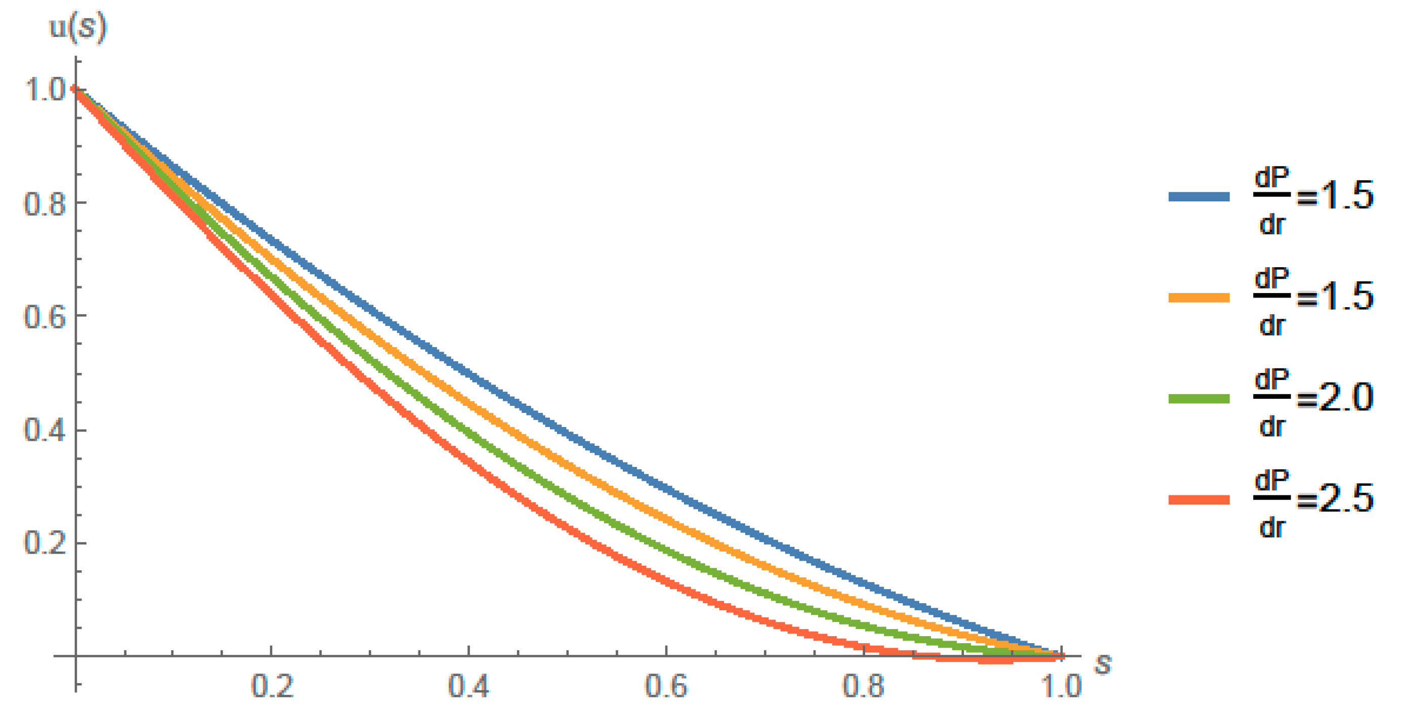
Figure 6 shows the values of u at different values of P r . Also, Figure 7 gives the nature of u at different values of P r and s .
The Equation (6) for the stress, after some manipulation becomes in dimensionless form as
p ( r , s ) = P r ( r , s ) + α ( d u d s ) 2
which is as
p = α [ 1 4 ( s 1 ) { β C 1 P r ( P r 2 ( 2 s 2 2 y + 1 ) + P r ( 4 8 s ) + 12 ) + β C 1 s P r ( P r 2 ( 4 s 2 ) 8 P r ) + 2 P r } + 1 4 ( β C 1 s P r ( P r 2 ( 2 s 2 2 s + 1 ) + P r ( 4 8 s ) + 12 ) + 2 s P r 4 ) ] 2 + P r .
For fixed values of β = 0.03 ,   P r = 2 in
u = 1 4 ( s 1 ) { β C 1 s P r ( P r 2 ( 2 s 2 2 s + 1 ) + P r ( 4 8 s ) + 12 ) + 2 s P r 4 } ;
give the value of constant C 1 = 0.6027727875127079 , then for different values of α , the values of stress p are calculated as shown in the Equations (45)–(48).
p ( α = 0.2 ) = 2 + 0.2 [ 1 4 ( s 1 ) { 0.0361664 ( 4 ( 2 s 2 2 s + 1 ) + 2 ( 4 8 s ) + 12 ) 0.0361664 s ( 4 ( 4 s 2 ) 16 ) + 4 } + 1 4 { 0.0361664 ( 4 ( 2 s 2 2 s + 1 ) + 2 ( 4 8 s ) + 12 ) s + 4 s 4 } ] 2 .
p ( α = 0.3 ) = 2 + 0.3 [ 1 4 ( s 1 ) { 0.0361664 ( 4 ( 2 s 2 2 s + 1 ) + 2 ( 4 8 s ) + 12 ) 0.0361664 s ( 4 ( 4 s 2 ) 16 ) + 4 } + 1 4 { 0.0361664 ( 4 ( 2 s 2 2 s + 1 ) + 2 ( 4 8 s ) + 12 ) s + 4 s 4 } ] 2 .
p ( α = 0.4 ) = 2 + 0.4 [ 1 4 ( s 1 ) { 0.0361664 ( 4 ( 2 s 2 2 s + 1 ) + 2 ( 4 8 s ) + 12 ) 0.0361664 s ( 4 ( 4 s 2 ) 16 ) + 4 } + 1 4 { 0.0361664 ( 4 ( 2 s 2 2 s + 1 ) + 2 ( 4 8 s ) + 12 ) s + 4 s 4 } ] 2 .
p ( α = 0.5 ) = 2 + 0.5 [ 1 4 ( s 1 ) { 0.0361664 ( 4 ( 2 s 2 2 s + 1 ) + 2 ( 4 8 s ) + 12 ) 0.0361664 s ( 4 ( 4 s 2 ) 16 ) + 4 } + 1 4 { 0.0361664 ( 4 ( 2 s 2 2 s + 1 ) + 2 ( 4 8 s ) + 12 ) s + 4 s 4 } ] 2 .
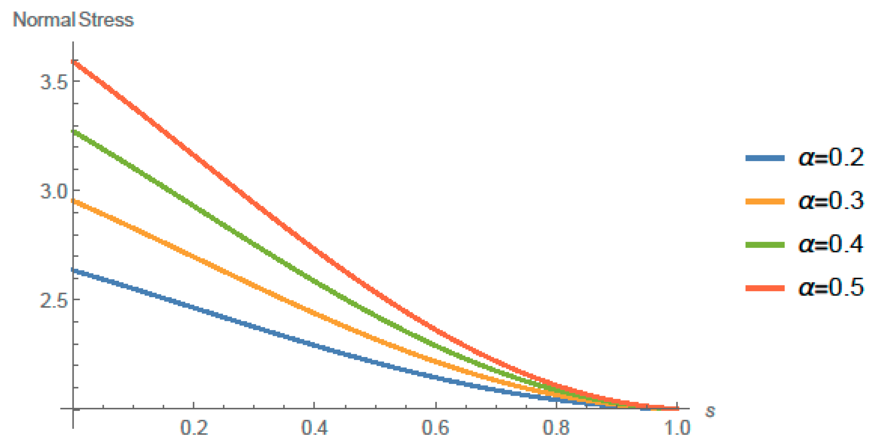
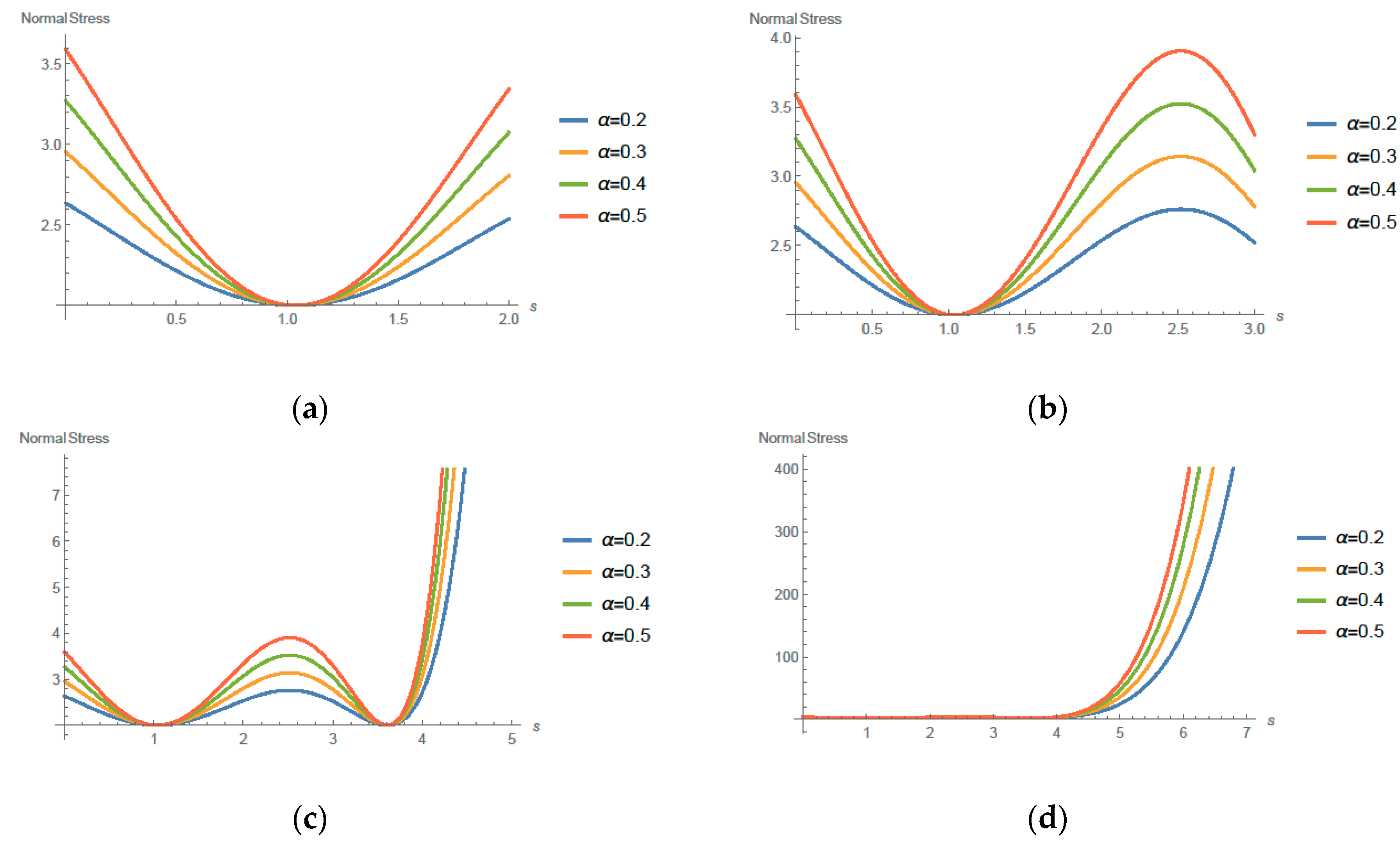
Figure 8 shows the values of stress p at different values of α . Also the Figure 9 gives the nature of p at different values of α and s . Stratagems the normal stress properties at altered locations of TGF coating progression in dissimilar standards it is perceived that strain upsurges with growing α for constant β . These results are in accordance with [29,30,31,32,33,34,35,36,37,38].
Figure 9 shows normal stress at different values of α . Stratagems the normal stress properties at altered locations of TGF coating process in various perspective. It is perceived that strain is increasing through the area of coating with growing α . Figure 2, Figure 3, Figure 4, Figure 5, Figure 6, Figure 7, Figure 8 and Figure 9 provide a TGF implementation of the blade thin film and in what way the dissimilar restrictions and physical constraints. Some results are represented in the form of graphs, though results are given in a tabularized arrangement.
Figure 2, Figure 3, Figure 4, Figure 5, Figure 6 and Figure 7 are the graphical representation of velocity for dissimilar non-Newtonian fluids’ parameters. These graphical representations designate that the velocity contours is the combination of Poiseuille and Couette kind of flow streams. In graphical representations of Figure 2, Figure 5 and Figure 6, velocity contours reduce with enhancing NNF parameter. Upsurge in the NNF factor β resembles the shear condensing consequence that rises the liquid viscidness and declines liquid speed as supported by [37,38,39,40,41,42,43]. Figure 8 shows behavior of normal stresses at dissimilar values of α . Figure 9 shows behavior of shear stresses at varying values of α and s .     Results   of   Figure 2, Figure 3, Figure 4 and Figure 5 obviously display β upsurges the NNF character upsurges, i.e., the shear thickening escalates that decreases the liquid flow rate.

5. Summary and Conclusions

In this work, TGF based coating model is investigated and its tranport behavior on the blade thin film where the stream is lying within the inflexible edge and the movable web. This effort examines the blade surface coating procedure for TGF. Lubrication approximation theory is employed to progress the main mathematical model for the TGF in the thin and slim conduit. Estimated results based on OHAM for velocities, pressure, and volumetric current rate. The thin film width, maximum pressure, and normal stresses are also been studied comprehensively. Our results strongly show that a third-order fluid performs as the surface coatings where the TGF transport is within inflexible blade and non-stationary system. Lubrication theory is employed to mature the major equation for the TGF in a thin conduit.

Author Contributions

Conceptualization, S.M. and S.I.; Investigation, T.M., K.N. and M.Z.; Data curation, M.A.; Writing—original draft preparation, T.M.; Writing—review and editing, T.M. M.Z. and W.Y.K.; Supervision, M.S.; Funding acquisition, W.Y.K.

Funding

This work was supported by the Basic Science Research Program through the National Research Foundation of Korea (NRF) grant funded by the Korea Government (Ministry of Science and ICT) (NRF-2017R1C1B5017786, 2018R1A4A1025998).

Conflicts of Interest

The authors declare no conflict of interest.

References

  1. Bhatti, S.; Zahid, M.; Rana, M.A.; Siddiqui, A.M.; Abdul Wahab, H. Numerical analysis of blade coating of a third-order fluid. J. Plast. Film Sheet. 2019, 35, 157–180. [Google Scholar] [CrossRef]
  2. Kandasamy, R.; Muhammad, R. Thermal radiation energy on squeezed MHD flow of Cu, Al2O3 and CNTs-nanofluid over a sensor surface. Alex. Eng. J. 2016, 55, 2405–2421. [Google Scholar]
  3. Tripathi, J.J.; Kedar, G.D.; Deshmukh, K.C. Generalized thermoelastic diffusion in a thick circular plate including heat source. Alex. Eng. J. 2016, 55, 2241–2249. [Google Scholar] [CrossRef]
  4. Javed, T.; Ahmad, H.; Ghaffari, A. Influence of radiation on vertical wavy surface with constant heat flux: Using Keller box scheme. Alex. Eng. J. 2016, 55, 2221–2228. [Google Scholar] [CrossRef] [Green Version]
  5. Banik, S.; Mallik, S.H.; Kanoria, M. Thermoelastic interaction with energy dissipation in an infinite solid with distributed periodicallyvarying heat sources. Int. J. Pure Appl. Math. 2007, 34, 231. [Google Scholar]
  6. Singh, B. Wave propagation in a generalized thermoelastic material with voids. Appl. Math. Comput. 2007, 189, 698–709. [Google Scholar] [CrossRef]
  7. Mallik, S.H.; Kanoria, M. Generalized thermoelastic functionally graded solid with a periodically varying heat source. Int. J. Solids Struct. 2007, 44, 7633–7645. [Google Scholar] [CrossRef]
  8. Hayat, T.; Farooq, S.; Alsaedi, A.; Ahmad, B. Numerical study for Soret and Dufour effects on mixed convective peristalsis of Oldroyd 8-constants fluid. Int. J. Therm. Sci. 2017, 112, 68–81. [Google Scholar] [CrossRef]
  9. Ailawalia, P.; Kumar, S.; Pathania, D.S. Internal heat source in thermoelastic microelongated solid under green lindsay theory. J. Theor. Appl. Mech. 2016, 46, 65–82. [Google Scholar] [CrossRef]
  10. Mallik, S.H.; Kanoria, M. A two dimensional problem for a transversely isotropic generalized thermoelastic thick plate with spatially varying heat source. Eur. J. Mech.-A/Solids 2008, 27, 607–621. [Google Scholar] [CrossRef]
  11. Das, P.; Kar, A.; Kanoria, M. Analysis of magneto-thermoelastic response in a transversely isotropic hollow cylinder under thermal shock with three-phase-lag effect. J. Therm. Stresses 2013, 36, 239–258. [Google Scholar] [CrossRef]
  12. Tripathi, J.; Warbhe, S.; Deshmukh, K.C.; Verma, J. Fractional order generalized thermoelastic response in a half space due to a periodically varying heat source. Multidiscip. Model. Mater. Struct. 2018, 14, 2–15. [Google Scholar] [CrossRef]
  13. Sur, A.; Kanoria, M. Analysis of thermoelastic response in a functionally graded infinite space subjected to a Mode-I crack. Int. J. Adv. Appl. Math. Mech. 2015, 3, 33–44. [Google Scholar]
  14. Abbas, I.A.; Marin, M. Analytical solution of thermoelastic interaction in a half-space by pulsed laser heating. Phys. E Low-Dimens. Syst. Nanostructures 2017, 87, 254–260. [Google Scholar] [CrossRef]
  15. Carapau, F.; Correia, P.; Grilo, L.M. Specific shear-dependent viscoelastic third-grade fluid model. AIP Conf. Proc. 2016, 1790, 140008. [Google Scholar]
  16. Middleman, S. Fundamentals of Polymer Processing; McGraw-Hill: New York, NY, USA, 1977. [Google Scholar]
  17. Ruschak, K.J. Coating flows. Annu. Rev. Fluid Mech. 1985, 17, 65–89. [Google Scholar] [CrossRef]
  18. Blake, T.D.; Ruschak, K.J.; Kistler, S.F.; Schweizer, P.M. Liquid Film Coating; Chapman & Hall: London, UK, 1997. [Google Scholar]
  19. Gaskell, P.H.; Savage, M.D.; Summers, J.L. The Mechanics of Thin Film Coatings. In Proceedings of the First European Coating Symposium, Leeds University, Leeds, UK, 19–22 September 1995; p. 424. [Google Scholar]
  20. Bourgin, P. Fluid Mechanics of Coating Processes. In Proceedings of the Euromech 367, 2nd European Coating Symposium (ECS’97), Universite Louis Pasteur, Strasbourg, France, 22–25 July 1997; p. 504. [Google Scholar]
  21. Sajid, M.; Ali, N.; Javed, M.A. An exact solution for the calendering analysis of a third-order fluid. J. Plast. Film Sheet. 2017, 33, 124–141. [Google Scholar] [CrossRef]
  22. Herisanu, N.; Marinca, V. Accurate analytical solutions to oscillators with discontinuities and fractional-power restoring force by means of the optimal homotopy asymptotic method. Comput. Math. Appl. 2010, 60, 1607–1615. [Google Scholar] [CrossRef] [Green Version]
  23. Marinca, V.; Herisanu, N. Determination of periodic solutions for the motion of a particle on a rotating parabola by means of the optimal homotopy asymptotic method. J. Sound Vib. 2010, 329, 1450–1459. [Google Scholar] [CrossRef]
  24. Iqbal, S.; Idrees, M.; Siddiqui, A.M.; Ansari, A.R. Some solutions of the linear and nonlinear Klein-Gordon equations using the optimal homotopy asymptotic method. Appl. Math. Comput. 2010, 216, 2898–2909. [Google Scholar] [CrossRef]
  25. Iqbal, S.; Javed, A. Application of optimal homotopy asymptotic method for the analytic solution of singular Lane-Emden type equation. Appl. Math. Comput. 2011, 217, 7753–7761. [Google Scholar] [CrossRef]
  26. Iqbal, S.; Ansari, A.R.; Siddiqui, A.M.; Javed, A. Use of optimal homotopy asymptotic method and Galerkin-s finite element formulation in the study of heat transfer flow of a third grade fluid between parallel plates. J. Heat Transf. 2011, 133, 091702. [Google Scholar] [CrossRef]
  27. Javed, A.; Memon, N.A.; Iqbal, S. Optimal homotopy asymptotic method for solving sixth-order boundary value problems. QUEST Res. J. 2010, 9, 6–10. [Google Scholar]
  28. Hashmi, M.S.; Khan, N.; Iqbal, S. Numerical solutions of weakly singular Volterra integral equations using the optimal homotopy asymptotic method. Comput. Math. Appl. 2012, 64, 1567–1574. [Google Scholar] [CrossRef] [Green Version]
  29. Hashmi, M.S.; Khan, N.; Iqbal, S. Optimal homotopy asymptotic method for solving nonlinear Fredholm integral equations of second kind. Appl. Math. Comput. 2012, 218, 10982–10989. [Google Scholar] [CrossRef]
  30. Younas, H.M.; Mustahsan, M.; Manzoor, T.; Salamat, N.; Iqbal, S. Dynamical study of fokker-planck equations by using optimal homotopy asymptotic method. Mathematics 2019, 7, 264. [Google Scholar] [CrossRef]
  31. Siddiqui, A.M.; Kaloni, P.N. Plane steady flows of a third grade fluid. Int. J. Eng. Sci. 1987, 25, 171–188. [Google Scholar] [CrossRef]
  32. Zahid, M.; Haroon, T.; Rana, M.A.; Siddiqui, A.M. Roll coating analysis of a third grade fluid. J. Plast. Film Sheet. 2017, 33, 72–91. [Google Scholar] [CrossRef]
  33. Siddiqui, A.M.; Zahid, M.; Rana, M.A.; Haroon, T. Calendering analysis of a third-order fluid. J. Plast. Film Sheet. 2014, 30, 345–368. [Google Scholar] [CrossRef]
  34. Sullivan, T.M.; Middleman, S. Film thickness in blade coating of viscous and viscoelastic liquids. J. Non-Newton. Fluid Mech. 1986, 21, 13–38. [Google Scholar] [CrossRef]
  35. Greener, Y.; Middleman, S. Blade-coating of a viscoelastic fluid. Polym. Eng. Sci. 1974, 14, 791–796. [Google Scholar] [CrossRef]
  36. Ross, A.B.; Wilson, S.K.; Duffy, B.R. Blade coating of a power-law fluid. Phys. Fluids 1999, 11, 958–970. [Google Scholar] [CrossRef]
  37. Hwang, S.S. Non-Newtonian liquid blade coating process. J. Fluids Eng. 1982, 104, 469–474. [Google Scholar] [CrossRef]
  38. Dien, I.K.; Elrod, H.G. A generalized steady-state Reynolds equation for non-Newtonian fluids, with application to journal bearings. J. Lubr. Technol. 1983, 105, 385–390. [Google Scholar] [CrossRef]
  39. Tichy, J.A. Non-Newtonian lubrication with the convected Maxwell model. J. Tribol. 1996, 118, 344–348. [Google Scholar] [CrossRef]
  40. Hsu, T.C.; Malone, M.; Laurence, R.L.; Middleman, S. Separating forces in blade coating of viscous and viscoelastic liquids. J. Non-Newton. Fluid Mech. 1985, 18, 273–294. [Google Scholar] [CrossRef]
  41. Fosdick, R.L.; Rajagopal, K.R. Thermodynamics and stability of fluids of third grade. Proc. R. Soc. Lond. A 1980, 369, 351–377. [Google Scholar] [CrossRef]
  42. Atif, H.M.; Ali, N.; Javed, M.A.; Abbas, F. Theoretical analysis of roll-over-web coating of a micropolar fluid under lubrication approximation theory. J. Plast. Film Sheet. 2018, 34. [Google Scholar] [CrossRef]
  43. Ali, N.; Atif, H.M.; Javed, M.A.; Sajid, M. A theoretical analysis of roll-over-web coating of couple stress fluid. J. Plast. Film Sheet. 2018, 34, 43–59. [Google Scholar] [CrossRef]
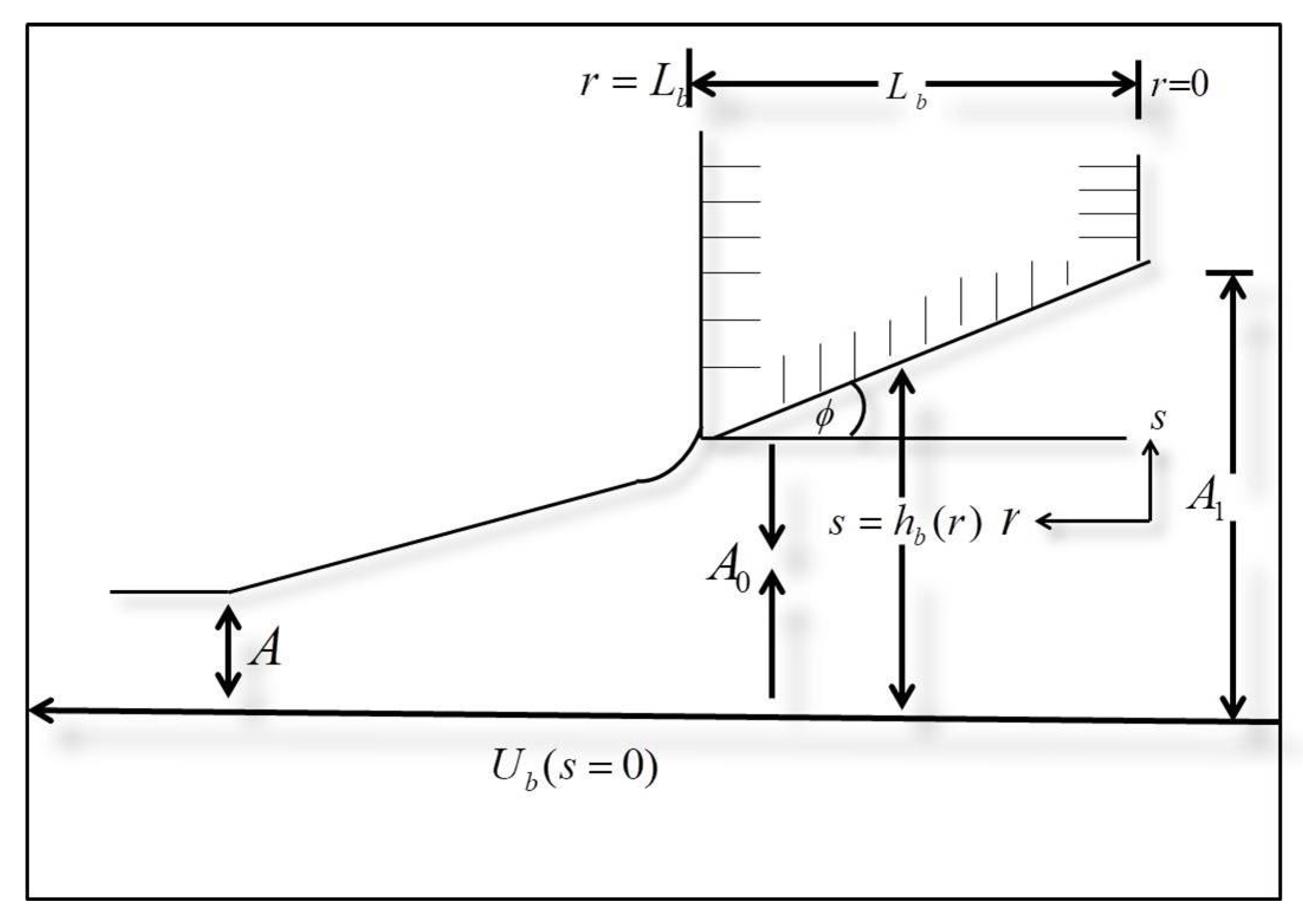
Figure 1. Blade coater geometry.
Coatings 09 00741 g001
Figure 2.     u ( s ) at different values of β .
Coatings 09 00741 g002
Figure 3. u ( s ) at different values of β and varying ranges of s . (a) with the s range of [0–2]; (b) with the s range of [0–3]; (c) with the s range of [0–5]; (d) with the s range of [0–10].
Coatings 09 00741 g003
Figure 4. λ at different values of P r = d P d r .
Coatings 09 00741 g004
Figure 5. λ at different values of P r and s . (a) with the s range of [0–2]; (b) with the s range of [0–3]; (c) with the s range of [0–7]; (d) with the s range of [0–12].
Coatings 09 00741 g005
Figure 6. u ( s ) at different values of d P d r .
Coatings 09 00741 g006
Figure 7. u ( s ) at different values of d P d r and s . (a) with the s range of [0–2]; (b) with the s range of [0–3]; (c) with the s range of [0–7]; (d) with the s range of [0–12].
Coatings 09 00741 g007
Figure 8. Normal Stress at different values of α .
Coatings 09 00741 g008
Figure 9. Normal stress at different values of α and s . (a) with the s range of [0–2]; (b) with the s range of [0–3]; (c) with the s range of [0–5]; (d) with the s range of [0–7].
Coatings 09 00741 g009
Table 1. Values of β and C 1 .
β and C1
β C1
0.03−0.6027727875127079
0.04−0.5367678225757836
0.050.4849617709110862
0.06−0.44305755184121864
Table 2. Values of P r and C 1 .
For Fixed β = 0.03
PrC1
1−0.7389837541589072
1.5−0.6670404279185341
2−0.6027727875127079
2.5−0.5456887819699325