Article

Comparative Study of Ni-Sn Alloys Electrodeposited from Choline Chloride-Based Ionic Liquids in Direct and Pulsed Current

1
Center for Surface Science and Nanotechnology, University POLITEHNICA of Bucharest, Splaiul Independentei 313, 060042 Bucharest, Romania
2
Department of Inorganic Chemistry, Physical Chemistry and Electrochemistry, Faculty of Applied Chemistry and Materials Science, University POLITEHNICA of Bucharest, Calea Grivitei 132, 010737 Bucharest, Romania
3
Department of Materials and Manufacturing, School of Engineering, Jönköping University, Gjuterigatan 5, 553 18 Jönköping, Sweden
4
Academy of Romanian Scientists, Splaiul Independentei 54, 050094 Bucharest, Romania
*
Author to whom correspondence should be addressed.
Coatings 2019, 9(12), 801; https://doi.org/10.3390/coatings9120801
Submission received: 1 November 2019 / Revised: 26 November 2019 / Accepted: 27 November 2019 / Published: 29 November 2019

Abstract

:
This work presents, for the first time, the electrodeposition of Ni-Sn alloys in pulse current, from deep eutectic solvents (choline chloride: ethylene glycol eutectic mixture). Additionally, in this study, we report a comparison of the electrodeposition methods known as pulse and direct current. The elemental composition of the films, evaluated from EDX, remained almost constant independently on the electrodeposition parameters. The XRD data revealed the presence of the NiSn metastable phase, which has been confirmed by DSC analysis. This phase shows a nanocrystalline structure with crystallite sizes between 12 and 20 nm. The use of pulse current electrodeposition method has led to an improvement of alloys’ mechanical properties. Moreover, by controlling the electrodeposition parameters, we succeeded in tuning the mechanical properties of the coatings prepared through the PC method. We showed that the hardness parameters exhibited by the Ni-Sn alloys are strongly dependent on their crystallite sizes.

1. Introduction

Metal coatings have been widely used in surface protection or as decorative applications. Tin is a soft metal and easy to melt (223 °C melting point). However, its low melting point makes it difficult to use in its pure state. When tin is combined with other metals such as nickel, the resulting alloys are suitable for a wide range of applications such as surgical instruments, watch pars, printed circuits boards, and electrical connectors, which represent an alternative to chromium decoration due to their good anticorrosive properties. Recently, they have been investigated as anode material in lithium ion batteries [1,2,3].
Nickel-tin alloys are usually electrodeposited from aqueous electrolytes containing chloride/fluoride or pyrophosphates compounds. Parkinson in 1950 reported, for the first time, the electrodeposition of a nickel-tin alloy with a composition of approximately 65/35 wt.% (1:1 atomic ratio), assigned as NiSn stoichiometry [4]. According to the thermodynamic phase diagram, the 1:1 intermetallic phase of nickel and tin cannot be obtained by pyrometallurgical processes [5,6]. The electrodeposition of Sn-based alloys from aqueous electrolytes is limited by the oxidation of Sn2+ to Sn4+ in the bath and sludge formation, which lead to the solution destabilization or requires the use of cyanide complex agents [7]. The oxidation of divalent to tetravalent tin species can be minimized in nonaqueous electrolytes [8]. Deep eutectic solvents (DES) represent an alternative for tin-based alloys depositions. They consist of binary eutectic mixtures where one component was a quaternary ammonium salt such as choline chloride (2-hydroxyethyl-trimethyl ammonium chloride) and the other component was a hydrogen bond donor species as amide, alcohol, or carboxylic acid [9,10]. The resulting analogue ionic liquids have a wide electrochemical window, high viscosity, and low volatility and are potentially biodegradable and recyclable. Moreover, promising applications of DES as (co)-solvents in organic and inorganic synthesis as well as biocatalysis applications have been reported [11,12,13]. They represent a “green alternative” for electrodeposition of metals and alloys [14,15,16,17]. The electrodeposition of tin and tin-zinc alloys from deep eutectic solvents have been studied by Abbott et al. [18] and Pereira et al. [19,20]. Our group investigated the electrodeposition of nickel-tin alloys, under direct current electrodeposition conditions, from different types of deep eutectic solvents, involving choline chloride: urea and choline chloride: ethylene glycol eutectic mixtures [21,22]. The obtained deposits were compact and adherent to the copper substrate.
Pulse plating represents an alternative to the direct current electrodeposition. It has been widely used to improve the electrodeposition of metals and alloys obtained from aqueous solutions [23,24,25]. However, its use in the electrodeposition from traditional ionic liquids (IL) or deep eutectic solvents is relatively new. To the best of our knowledge, only a few studies regarding the pulse electrodeposition from ILs and DESs have been carried out for Al, Ta, Cu, Pd, and Fe [26,27,28,29]. Manolova and Böck reported that the pulse electrodeposition of palladium from choline chloride: urea eutectic mixtures produced compact Pd structures without microcracks [26]. Xing et al. studied the pulse electrodeposition of copper from choline chloride: ethylene glycol and observed an improvement in the current efficiency [29]. To the best of our knowledge, this paper is the first to study the pulse electrodeposition of Ni-Sn alloys from deep eutectic solvents especially since no systematic studies have been reported on the effect of applied pulse frequencies on the morphology and mechanical properties.
In this study, we report the electrodeposition of nickel-tin alloys under direct current and, also, as we mentioned above, in pulse current conditions from choline chloride: ethylene glycol eutectic mixture (1:2 mole ratio), which contains different amounts of the metallic salts. Additionally, the effect of pulse current parameters on the deposit’s morphology, crystallite size, and mechanical properties has been investigated. The use of pulse current has led to the formation of coatings with smaller crystallite sizes and improved mechanical properties compared to those obtained in direct current plating. By changing the electrodeposition parameters, it was possible to modulate the mechanical properties.

2. Materials and Methods

The electrolytes were synthetized by mixing choline chloride (ChCl) (Emprove Merck, 98%, Darmstadt, Germany) and ethylene glycol (EG) (Silal Trading Bucharest, 99%, Bucharest, Romania) in a 1:2 molar ratio and heating at 80 ± 5 °C, with gentle magnetic stirring (200 rpm) until a homogeneous, colourless liquid was formed. To this analogue ionic liquid (ILEG), tin chloride (SnCl2·2H2O) (Acros Thermo Fisher Scientific, 97%, Geel, Belgium), and nickel chloride (NiCl2·6H2O), (Lach-Ner Neratowitz, 99%, Neratowitz, Czech) salts were added at 80 ± 5 °C in different ratios, as shown in Table 1. All the reagents were used as received.
The electrodeposited coatings have been prepared in a galvanostatic mode, under magnetic stirring (200 rpm) and using a pulse-reverse power supply (pe86CB3HE, Plating Electronic GmbH, Denzlingen, Germany). The deposition was carried out in an open system at 75 ± 5 °C in a two-electrode configuration. The cathodes were copper sheets, which have a thickness of 0.2 mm and a surface area of 0.75 cm2. Prior to the electrodeposition, the substrates were cleaned with acetone and rinsed with deionized water, which was followed by chemical pickling in HNO3:H2O solution (1:1 vol.%) at room temperature for 30 s. Then the copper sheets were rinsed with deionized water and air dried. A platinized titanium mesh was used as an anode.
The Ni-Sn alloys were obtained by plating using two different methods: direct current (DC) and pulse plaiting (PC). For DC electrodeposition, three different current densities (5, 10, and 15 mA/cm2) were applied during 30 min at 75 ± 5 °C. In PC, the average current density was fixed at 6.67 mA/cm2, as well as the duty cycle (ϴ = 0.33), and different frequencies were applied: 0.067, 0.67, and 6.7 Hz for 120 min, at the same temperature. The obtained Ni-Sn deposits were rinsed with acetone, rinsed with deionized water, and air dried.
Morphological and compositional property studies of the Ni-Sn alloys were performed by Scanning Electron Microscopy (SEM) (Tokyo, Japan) using a Hitachi SU 8230 system equipped with an Oxford Energy Dispersive X-ray detector (EDX) (High Wycombe, United Kingdom). The structural properties of the coatings were investigated by Rigaku SmartLab X-ray Diffractometer (XRD) system (Tokyo, Japan) equipped with Cu Kα radiation (λ = 0.15406 nm), operating at room temperature in the 2θ range 5°–90°.
The phase transformations of Ni-Sn alloys under heat treatment were studied by Differential Scanning Calorimetry (DSC) (Selb, Germany) with a Netzsch 404C Pegasus instrument in a purified argon atmosphere, at a scanning rate of 20 °C/min, from room temperature up to 500 °C.
The mechanical properties of the samples were evaluated by nanoindentation tests performed on a NanoTestTM Vantage system (Wrexham, United Kingdom) using a three-sided pyramidal Berkovich diamond tip. In order to avoid the interference of the substrate, the electrodeposited coatings were indented in a cross-section. At least 10 measurements were performed on each sample. A load of 20 mN was applied and the hardness H was determined, according to the following expression [30].
H   =   P m a x A
where Pmax is the maximum applied load measured at the maximum depth of penetration and A is the projected area determined by the equation below.
A   =   23.96 h f 2
where hf is the contact indentation depth obtained from the total depth (hmax) using the following formula.
h f   =   h m a x ε P m a x S
In Equation (3), ε is a geometrical parameter having a value of 0.75 for a pyramidal indenter, P is the maximum applied load, and S is the contact stiffness determined from the following relationship.
S   =   β   2 π E r A
where β is a correction factor and Er is the reduced elastic modulus defined by the equation below.
1 E r   =   1   υ s 2 E s   +   1   υ i 2 E i
Es is the specimen elastic modulus, and Ei and υ i,s are the elastic modulus and the Poisson’s ratio, respectively.

3. Results and Discussion

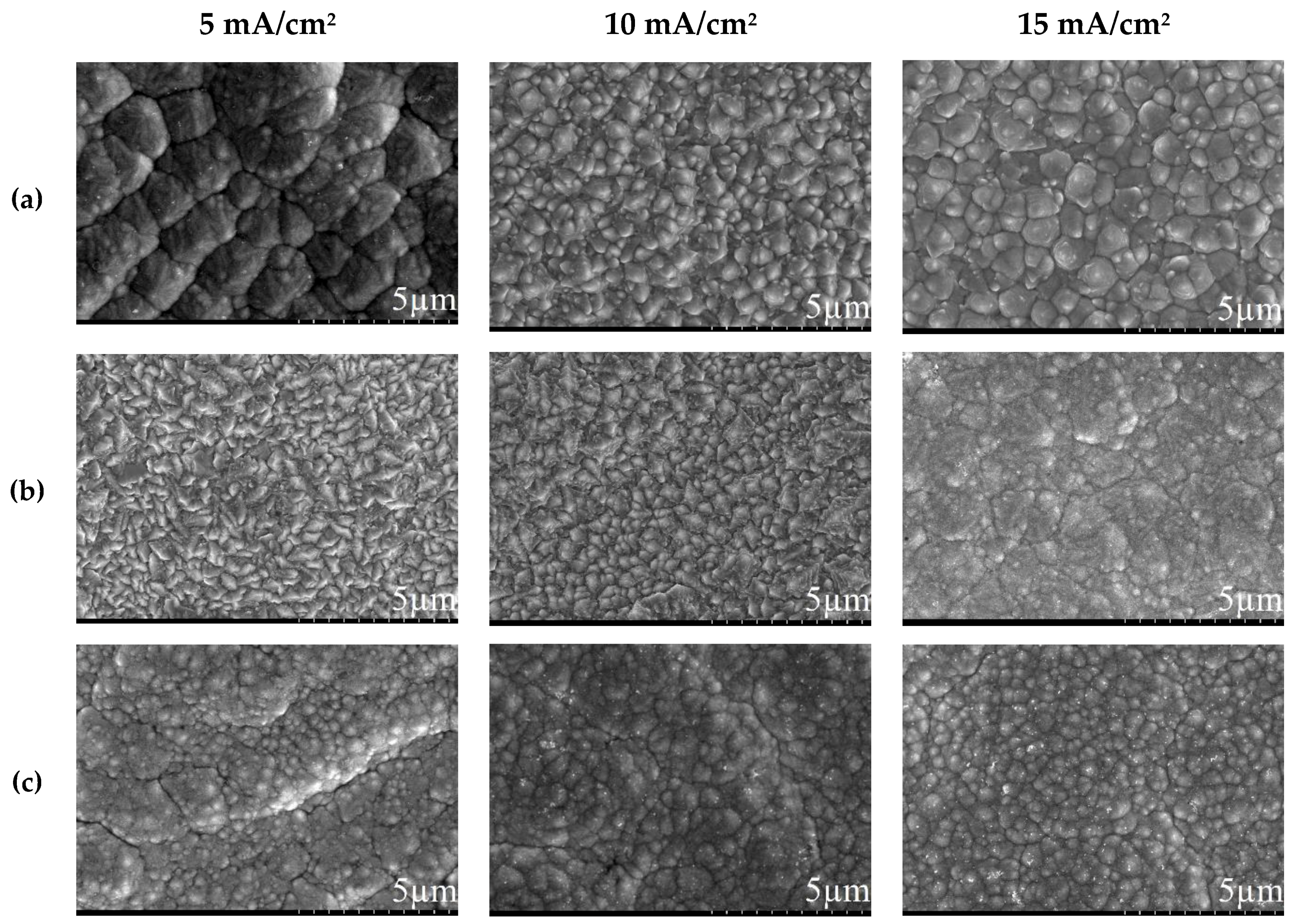
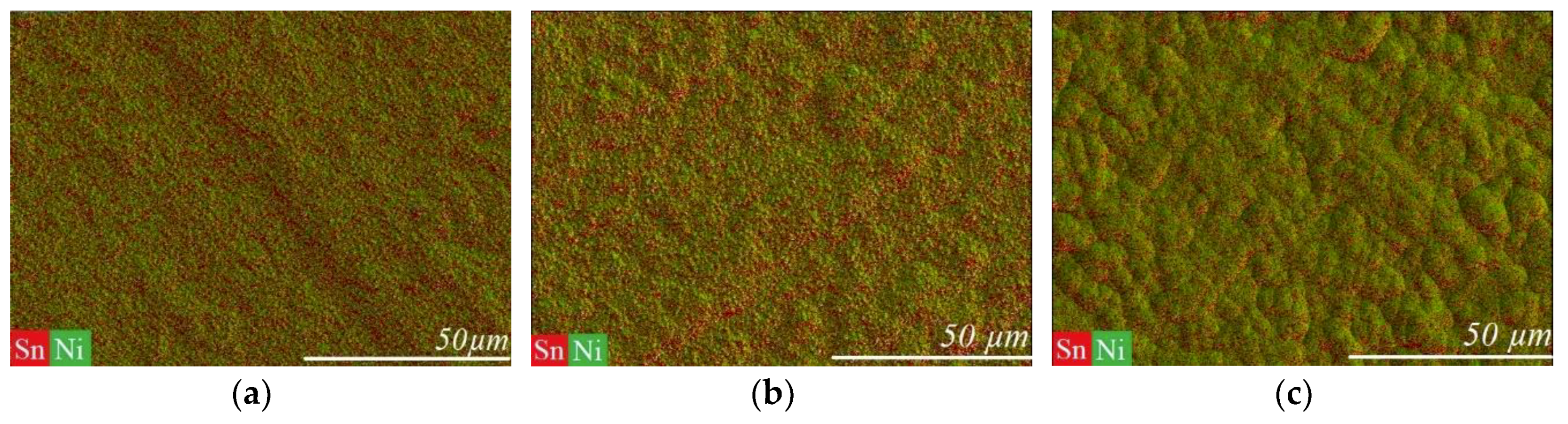
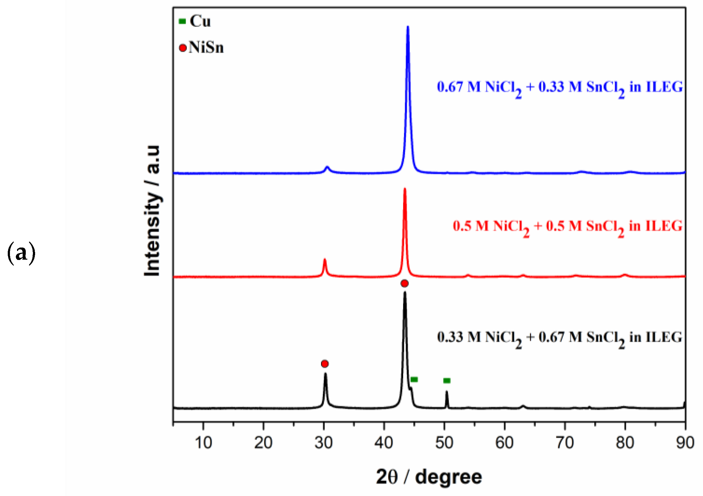
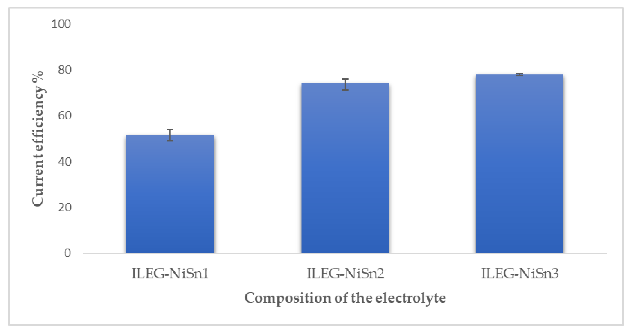
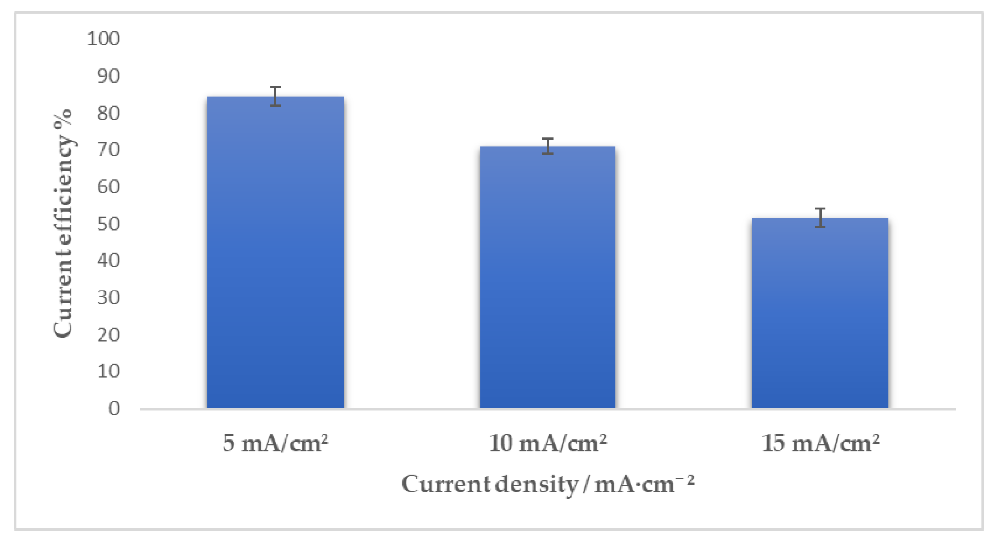
3.1. Direct Current Electrodeposition of Nickel-Tin Alloys

Different amounts of nickel and tin salts have been added to a DES of choline chloride: ethylen glycol (ILEG), which results in three different types of electrolytes: ILEG-NiSn1, ILEG-NiSn2, and ILEG-NiSn3, as shown in Table 1. All the mixtures were in a liquid state at room temperature, with a green colour, and electrical conductivities in the range of 2–12 mS/cm for temperatures between 25–80 °C.
Nickel tin alloys have been electrodeposited in DC on Cu substrates in a galvanostatic mode, at different current densities. The obtained deposits were bright, grey, and adherent to the copper substrates. The coatings exhibited different calculated thicknesses (using Faraday’s law) in the range of 4 to 10 µm, depending on the applied current density. Figure 1 shows examples of SEM micrographs of Ni-Sn deposits obtained from the different ILEG-NiSn systems.
As shown in Figure 1, no dendritic growth was observed. Different surface morphologies defined by acicular (ILEG-NiSn2), circular (ILEG-NiSn3), and quasi-circular (ILEG-NiSn1) features have been identified, as a result of the variation of current density and the electrolyte nature. The Ni-Sn coatings prepared from the ILEG-NiSn3 system did not exhibited any significant difference in morphology with the variation of the applied current density, where all the coatings seem to be formed from relatively ordered circular grains. Jellesen and Møller observed a similar morphology for electrodeposited Ni-Sn alloys from an aqueous fluoride bath [6].
The chemical composition of the deposited films was determined by EDX. The EDX elemental maps for the samples prepared at 15 mA/cm2 from different types of electrolytes reveal a good chemical homogeneity of the Ni-Sn coatings (see Figure 2). Moreover, we noticed that the composition of the deposits is not influenced by the electrodeposition parameters such as current density and mole ratio of salts in the electrolytes. As can be observed in Table 2, the weight percentages determined by EDX are around 32 wt.% Ni and 68 wt.% Sn (approximately 1:1 atomic Ni:Sn). It should be mentioned that our results are in good agreement with the studies reported by Parkinson, who observed that variations between 20%–30% in the molar ratio of metal ions and/or in the temperature do not induce significant changes in the composition of the alloys electrodeposited from aqueous-based electrolytes [4].
The XRD patterns obtained from different types of electrolytes are represented in Figure 3. For the Ni-Sn alloy prepared from ILEG-NiSn1 electrolyte, the XRD pattern was plotted using a logarithmic scale in order to show the low intensity peaks. The diffraction peaks at 2θ = 30.50°, 43.77°, 54.61°, 60.15°, 63.61°, 72.66°, 80.69°, and 89.92° were assigned to NiSn metastable phase and the peaks at 2θ = 44.32°, 50.48°, and 74.10° were attributed to the copper substrate (card No.: 00-004-0836) [31]. The formation of the metastable phase NiSn is independent on the concentration ratio of metal salts in the electrolyte. The formation of the NiSn metastable phase has been explained by several authors. This phase has a hexagonal network with a structure similar to Ni3Sn2 stable phase, where additional tin is incorporated into the alloy by inducing modifications in the lattice constants, which was found by Rooksby [31]. Parkinson tried to find an explanation of the formation of this compound suggesting that the free energy for its formation is lower than the one of the other possible nickel-tin compounds [4]. Additionally, a change in the occupancy of Ni atoms in the unit cell of the stable phase Ni3Sn2 can lead to the NiSn metastable phase as proposed by Watanable et al. [32]. Another explanation proposed by Lo is that the NiSn alloy is actually formed by the Ni3Sn2 phase with Sn atoms segregated at the grain boundaries [33].
The presence of copper peaks has been observed only for the sample electrodeposited from the ILEG-NiSn1 system, which means that this prepared film has a lower thickness as compared to the other samples, which can be seen in Figure 3b. To confirm this assumption, the current efficiency of the NiSn electrodeposited films was determined. The current efficiency refers to the ratio between the actual mass deposited vs. the one predicted theoretically. The deposit obtained from the ILEG-NiSn1 system showed, as expected, the lowest current efficiency, at around 50% (Figure 4). Meanwhile, the samples prepared based on the other systems, ILEG-NiSn2 and ILEG-NiSn3, revealed a current efficiency between 75% to 78%. The lowest current efficiency was observed when the nickel to tin ratio was below one.
For all ILEG-NiSn systems, a decrease in the current efficiency with the increase of the current density was noticed (see in Figure 5 an example for the ILEG-NiSn1 system) caused by the faster depletion of the active metal ions near the cathodic surface at higher current densities [34].
The formation of the metastable phase NiSn was confirmed by heat treatment studies using differential scanning calorimetry. As seen in Figure 6, one exothermic peak is observed at 292 °C. This peak is associated with the transformation of NiSn in both Ni3Sn2 and Ni3Sn4 phases, which confirms that the metastable phase was obtained by electrodeposition, as described by Dutta and Clarke [35]. After completing the phase transformation, the sample was subjected to a second thermal cycle (2nd DSC measurement), where no peak was observed, which indicates the irreversibility of the process.

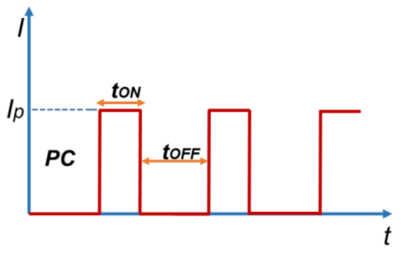
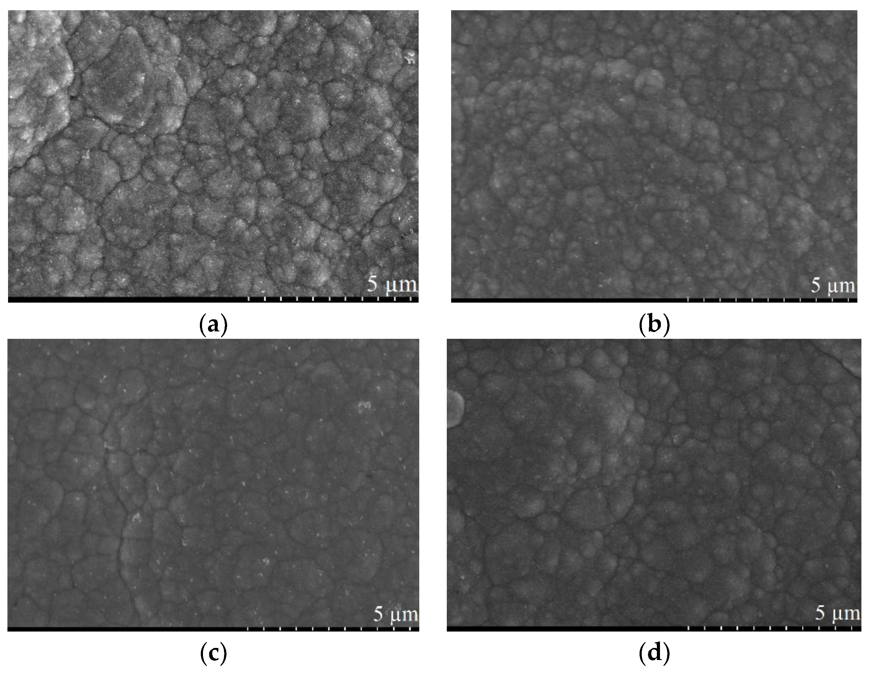
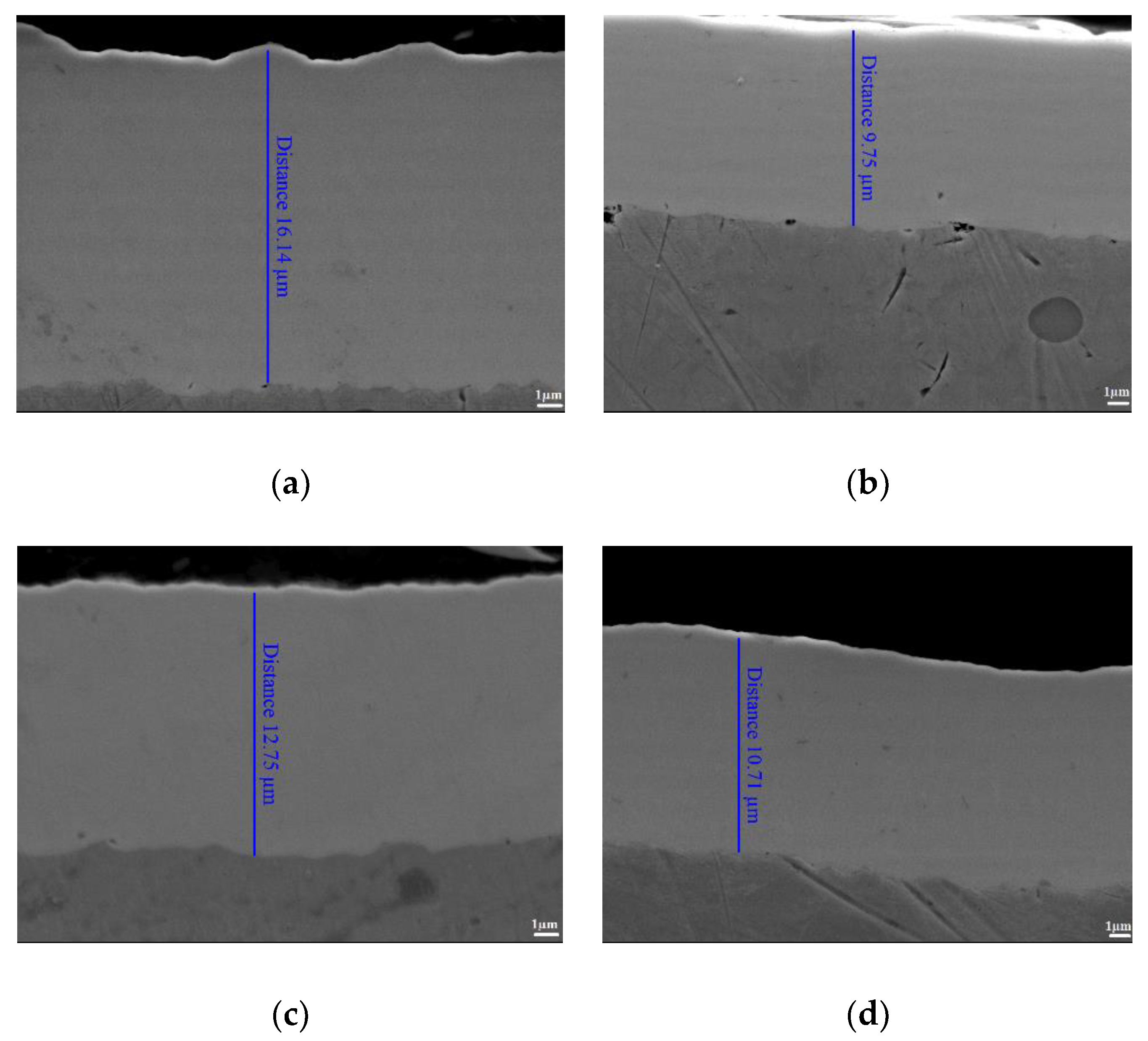
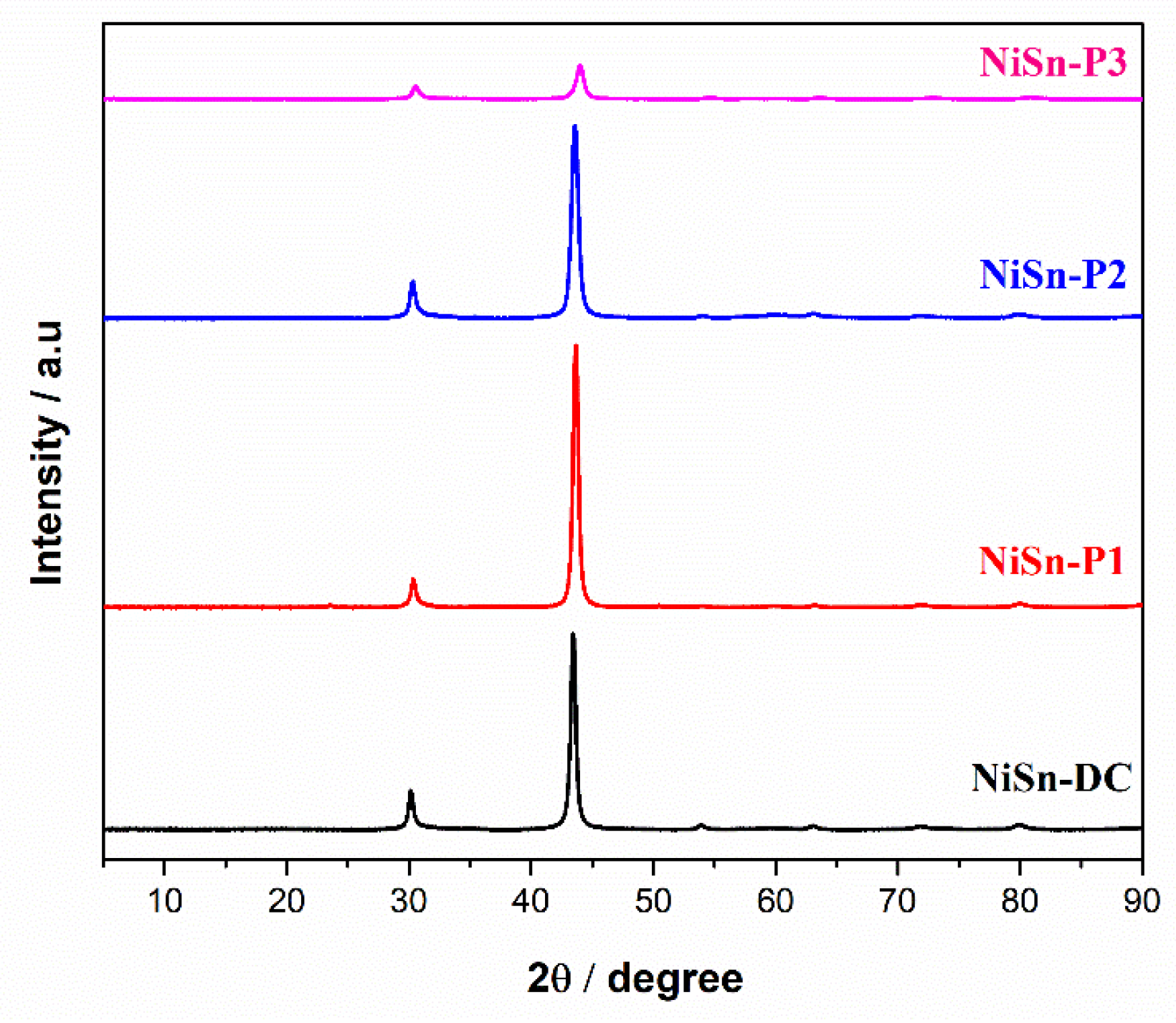
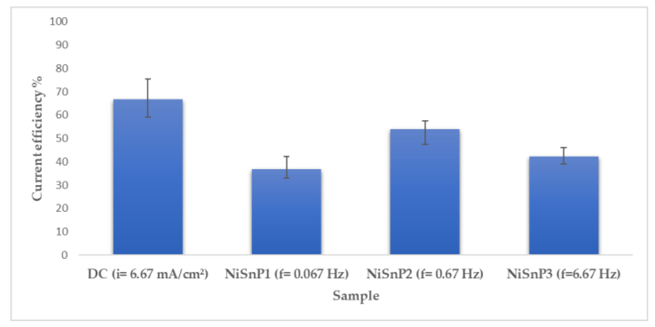
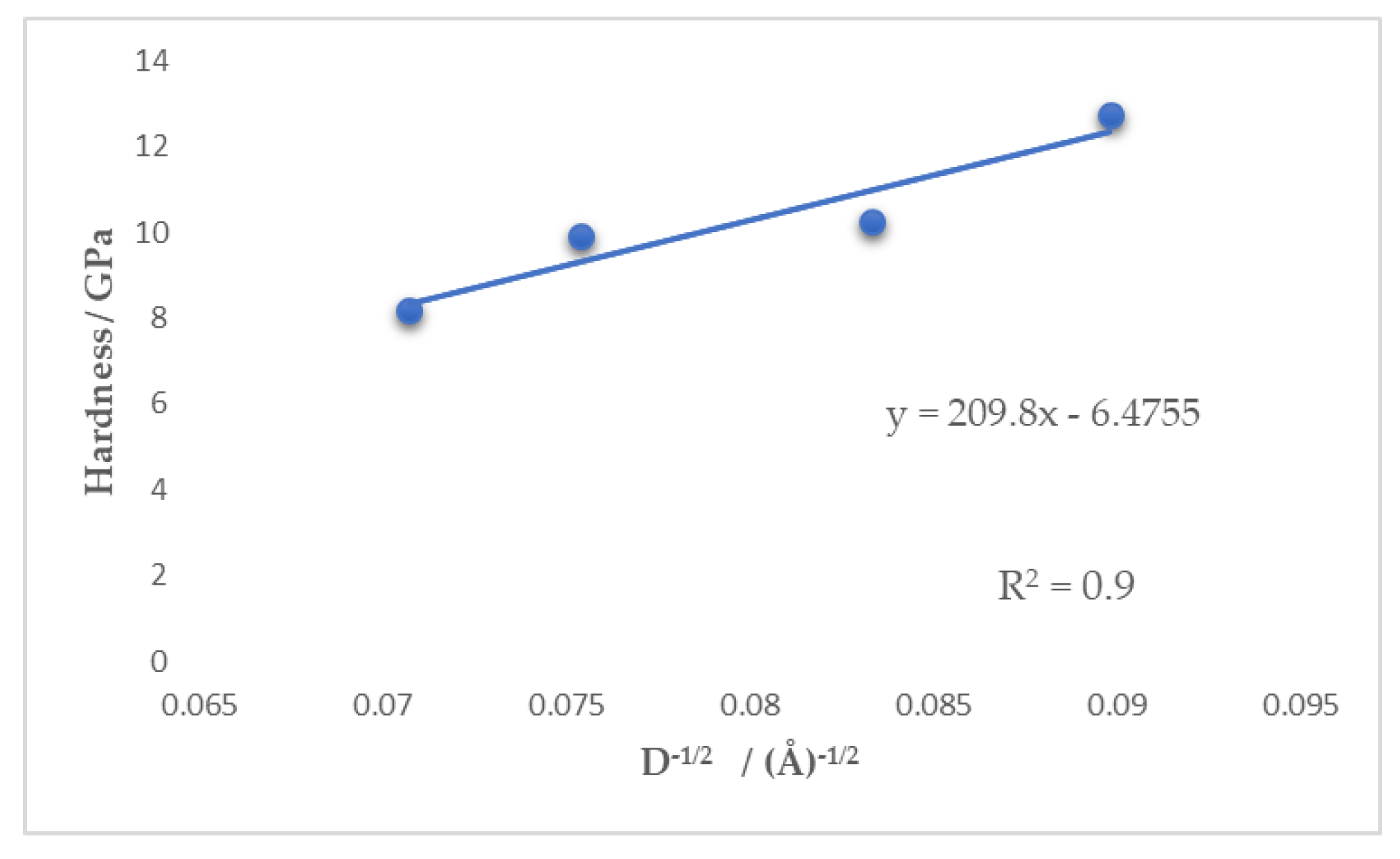
3.2. Pulse Current Electrodeposition of Nickel-Tin Alloys

The second part of the study was focused on the electrodeposition of Ni-Sn coatings in pulse current plating. To the best of our knowledge, this is the first time when nickel tin alloys were electrodeposited from deep eutectic solvents in pulse current. The influence of pulse current in the morphology, composition, and mechanical properties of the deposited Ni-Sn coatings has been investigated. The schematic diagram of the pulse plating wave is represented in Figure 7, where ip indicates the peak current density (mA/cm2) and TON and TOFF refer to the on and off time durations of the pulse. The average current density has been determined, according to the following expression.
i a v =   i p   t O N T O N   +   T O F F
where the frequency f (Hz) and the duty cycle θ are given by the equations below.
f   =   1 T O N   +   T O F F
θ   =   T O N T O N   +   T O F F
Both the average current density in PC and the current density in DC were set to 6.67 mA/cm2. Moreover, in this study, the value of the duty cycle was fixed at 0.33. Due to the fact that the composition of the Ni-Sn coating is independent of the concentration of the metal salts in ILEG, we have continued our studies considering only the electrolyte containing an equal amount of nickel and tin salts (ILEG-NiSn2 system). The other operating parameters are summarized in Table 3.
The surface morphology and the composition of the obtained Ni-Sn deposits were characterized by SEM-EDX. As shown in Figure 8, there are no noticeable differences in the surface morphology between the coating prepared in direct current and the ones obtained in pulse current electrodeposition conditions. All the deposits showed circular grains distributed over the entire surface. Additionally, no considerable differences have been observed in the composition of the coatings. The thicknesses of the coatings varied between 9 to 16 µm, as can be observed from the cross-section SEM images, illustrated in Figure 9.
The XRD patterns (Figure 10) indicate the presence of the diffraction peaks assigned to the same metastable phase NiSn, as described in the previous section. As can be observed in the patterns, all the analysed coatings reveal a preferred orientation known as the (110) plane. The position of this peak (θ-Bragg’s angle) and the values of the full width at half maximum (β-FWHM) were used in the Scherrer’s equation in order to determine the crystallite size, D, for each sample.
D   =   k λ β   cos ( θ )
where k is the Scherrer’s constant (considered as 0.94) and λ is the X-ray wavelength of the Cu Kα line [36].
The estimated crystallite sizes obtained by Scherrer’s equation were: 20 nm for NiSn-DC, 17.6 nm for NiSn-P1, 14.4 nm for NiSn-P2, and 12.4 nm for NiSn-P3. All samples prepared under pulse electrodeposition conditions showed a smaller crystallite size as compared to NiSn-DC. In the direct plating, the current is always in on-time and the metal ions are reduced continuously at the cathodic site, which leads to an increase of the crystallite domains. The applied frequency influences the crystallite size. By increasing the frequency, from 0.067 Hz to 6.67 Hz, a reduction of the crystallite size was observed. The use of high pulse frequencies, with short off-time, results in a crystallite refinement because the metallic ions do not have enough time to reduce at the cathodic surface.
Moreover, the cathodic current efficiency determined for the samples prepared under pulse electrodeposition conditions was lower than the one observed in DC (see Figure 11). Several factors can lead to a decrease in the current efficiency in pulse current electrodeposition such as the electrodissolution of metal during TOFF or side reactions (hydrogen evolution, metal degradation, fails of the embodiment of the adatoms in the crystal structure, etc.) during the on-time [34]. Vicenzo et al. found that the cathodic current efficiency of the pulse plating of Sn decreased with either the increase of the pulse frequency or decrease of the duty cycle [37]. For tin electrodeposition, the decrease of the current efficiency is dependent on the on-time. At shorter on-time, the discharge of the metal cation cannot be sustained because the overpotential is not fully fixed on the cathodic surface [34]. Ecker et al. have found that the current efficiency presents a maximum value for a specific ratio between the on-time and off-time for pulse plating of molybdenum and chromium-molybdenum alloy [38]. In our study, the maximum current efficiency for pulse electrodeposition conditions was observed for TON = 500 ms and TOFF = 1000 ms.
The use of pulse plating has numerous advantages, such as the decrease of hydrogen embrittlement, reduction of the porosity, and internal stresses as well as the increase in the hardness of the coatings [39,40,41,42]. Mohan et al. reported an increase in the hardness of a nickel deposit from 190 HV when direct electrodeposition conditions were used up to a 300 HV value when nickel was plated in the pulse current [42]. Moreover, the increase in the pulse frequency was found to improve the hardness of tin electrodeposited from a sulphate bath, as Mohan and Rajasekaran reported [42].
In the present study, the micro-mechanical properties of NiSn-DC, NiSn-P1, NiSn-P2, and NiSn-P3 samples were investigated in the cross-section. Table 4 shows the Ni-Sn films properties for samples obtained in both DC and PC conditions. As shown in this table, the use of pulse current improves the mechanical properties of the coatings as compared to DC. By increasing the frequency, a gradual increase in the hardness was observed from 9.92 GPa at 0.067 Hz, up to 12.73 GPa at 6.7 Hz. At short on-time, the diffusion layer is not extended completely on the solution, which leads to fine grain deposits that decrease the porosity of the coatings and improve their mechanical properties [42].
Moreover, a linear dependence between the hardness parameters and the inverse square root of crystallite sizes for Ni-Sn alloys has been observed, with a correlation factor of R2 = 0.9, which can be seen in Figure 12.
It seems that the hardness parameters revealed by the Ni-Sn coatings are dependent on their crystallite sizes, which showed a decreasing tendency with the increase of the electrodeposition frequency. There is a noteworthy similarity between this dependency (Figure 12) and described by the classical Hall-Petch relation, which considers the grain size instead of the crystallite size. Therefore, we succeeded in tuning the mechanical properties of the prepared coatings by diminishing their crystallite sizes through the electrodeposition parameters.

4. Conclusions

We successfully synthetized Ni-Sn alloys from choline chloride:ethylen glycol (1:2) using two different methods known as DC and PC, where the last one mentioned was reported for the first time in the literature. In the present study, we demonstrated that the composition of the electrodeposited Ni-Sn alloys remains almost constant, regardless of the electrolyte composition and applied current density. The XRD analysis revealed the presence of the metastable phase NiSn (1:1 atomic). Additionally, this metastable phase was confirmed by differential scanning calorimetry analysis where a peak was observed at 292 °C, which indicates the irreversible transformation of NiSn (1:1) into stable Ni3Sn2 and Ni3Sn4 phases. Moreover, we demonstrated that the use of pulse current electrodeposition conditions leads to a decrease of the crystallite size. The Ni-Sn alloy coatings obtained in pulse current showed an improvement in the mechanical properties as compared to the ones obtained in DC.

Author Contributions

Experimental investigation, writing-original draft preparation, S.P.R. XRD analysis, A.G.P. Electrodeposition methodology, A.P. Project administration, A.C. Electrodeposition methodology, analysis, S.C. DSC, Nanoindentation resources and discussion C.Z. SEM, XRD resources, discussion, M.E. Writing—review, discussion, supervision, T.V. Conceptualization and analysis, writing-review and editing, L.A.

Funding

The European Union’s Horizon 2020 research and innovation programme under the MARIE- SKŁODOWSKA-CURIE, grant number 764977” funded this research.

Acknowledgments

The PhD student expresses her appreciation to the Department of Materials and Manufacturing of Jönköping University for the kind permission to use the laboratories systems.

Conflicts of Interest

The authors declare no conflict of interest.

References

  1. Stuttle, C.J. The electrodeposition of tin coatings from deep eutectic solvents and their subsequent whiskergrowth. Ph.D. Thesis, Loughborough University, Loughborough, UK, 2014. [Google Scholar]
  2. Jalota, S. Tin-nickel alloy plating. Met. Finish. 2002, 100, 307–310. [Google Scholar] [CrossRef]
  3. Rudnik, E.; Włoch, G.; Czernecka, A. The influence of potential-current conditions on the electrodeposition of Ni-Sn alloys from acidic chloride-sulphate solution. Arch. Metall. Mater. 2014, 59, 195–198. [Google Scholar] [CrossRef]
  4. Parkinson, N. The electrodeposition of bright tin-nickel alloy plate. Trans. IMF 1950, 27, 129–151. [Google Scholar] [CrossRef]
  5. Watanabe, T. Formation of metastable phases by the plating method. Mater. Sci. Eng. A 1994, 179–180, 193–197. [Google Scholar] [CrossRef]
  6. Jellesen, M.S.; Moller, P. The electrochemical deposition of tin-nickel alloys and the corrosion properties of the coating. Plating Surf. Finish. 2005, 36–41. [Google Scholar]
  7. Nobel, F.; Ostrow, B.D.; Learonal Inc. Limiting tin sludge formation in tin or tin/lead electroplating solutions. US Patent 5066367 Appl. 07/585768, 1991. [Google Scholar]
  8. Ghosh, S.; Roy, S. Codeposition of Cu-Sn from ethaline deep eutectic solvent. Electrochim. Acta. 2015, 183, 27–36. [Google Scholar] [CrossRef]
  9. Abbott, A.; Boothby, D.; Capper, G.; Davies, D.; Rasheed, R. Deep eutectic solvents formed between choline chloride and carboxylic acids: Versatile alternatives to ionic liquids. J. Am. Chem. Soc. 2004, 126, 9142–9147. [Google Scholar] [CrossRef]
  10. Abbott, A.; Capper, G.; Davies, D.; Rasheed, R.; Tambyrajah, V. Novel solvent properties of choline chloride/urea mixtures. Chem. Commun. 2002, 70–71. [Google Scholar]
  11. Abbott, A.; Bell, T.; Handa, S.; Stoddart, B. O-acetylation of cellulose and monosaccharides using a zinc based ionic liquid. Green Chem. 2005, 7, 705. [Google Scholar] [CrossRef]
  12. Abbott, A.; Capper, G.; Davies, D.; McKenzie, K.; Obi, S. Solubility of metal oxides in deep eutectic solvents based on choline chloride. J. Chem. Eng. Data 2006, 51, 1280–1282. [Google Scholar] [CrossRef]
  13. Domínguez de María, P.; Maugeri, Z. Ionic liquids in biotransformations: From proof-of-concept to emerging deep-eutectic-solvents. Curr. Opin. Chem. Biol. 2011, 15, 220–225. [Google Scholar] [CrossRef] [PubMed]
  14. Abbott, A.; McKenzie, K. Application of ionic liquids to the electrodeposition of metals. Phys. Chem. Chem. Phys. 2006, 8, 4265. [Google Scholar] [CrossRef] [PubMed]
  15. Whitehead, A.; Pölzler, M.; Gollas, B. Zinc electrodeposition from a deep eutectic system containing choline chloride and ethylene glycol. J. Electrochem. Soc. 2010, 157, D328–D334. [Google Scholar] [CrossRef]
  16. Haerens, K.; Matthijs, E.; Chmielarz, A.; Van der Bruggen, B. The use of ionic liquids based on choline chloride for metal deposition: A green alternative? J. Environ. Manage. 2009, 90, 3245–3252. [Google Scholar] [CrossRef]
  17. Abbott, A.; Endres, F.; MacFarlane, D. Electrodeposition from Ionic Liquids, 2nd ed.; Wiley-VCH: Weinheim, Germany, 2017. [Google Scholar]
  18. Abbott, A.; Capper, G.; McKenzie, K.; Ryder, K. Electrodeposition of zinc–tin alloys from deep eutectic solvents based on choline chloride. J. Electroanal. Chem. 2007, 599, 288–294. [Google Scholar] [CrossRef]
  19. Pereira, N.; Pereira, C.; Silva, A. The effect of complex agents on the electrodeposition of tin from deep eutectic solvents. ECS Electrochem. Lett. 2012, 1, D5–D7. [Google Scholar] [CrossRef]
  20. Pereira, N.; Salomé, S.; Pereira, C.; Fernando Silva, A. Zn–Sn electrodeposition from deep eutectic solvents containing EDTA, HEDTA, and Idranal VII. J. Appl. Electrochem. 2012, 42, 561–571. [Google Scholar] [CrossRef]
  21. Cojocaru, A.; Costovici, S.; Anicai, L.; Visan, T. Studies of cathodic processes during NiSn alloy deposition using choline chloride based ionic liquids. Metal. Int. 2009, 14, 1–11. [Google Scholar]
  22. Anicai, L.; Petica, A.; Costovici, S.; Prioteasa, P.; Visan, T. Electrodeposition of Sn and NiSn alloys coatings using choline chloride based ionic liquids—evaluation of corrosion behavior. Electrochim. Acta 2013, 114, 868–877. [Google Scholar] [CrossRef]
  23. Kharmachi, I.; Dhouibi, L.; Berçot, P.; Rezrazi, M. Pulse plating as an alternative approach to improve Ni-Co alloys properties coated from a bath with a low nickel content. J. Mater. Environ. Sci. 2016, 7, 1670–1684. [Google Scholar]
  24. Ramanauskas, R.; Gudavičiūtė, L.; Ščit, O.; Bučinskienė, D.; Juškėnas, R. Pulse plating effect on composition and corrosion properties of zinc alloy coatings. Trans. IMF 2008, 86, 103–108. [Google Scholar] [CrossRef]
  25. Raub, C.; Knödler, A. The electrodeposition of gold by pulse plating. Gold Bull. 1977, 10, 38–44. [Google Scholar] [CrossRef]
  26. Manolova, M.; Böck, R. Electrodeposition of Pd from a deep eutectic solvent system: Effect of additives and hydrodynamic conditions. Trans. IMF 2019, 97, 161–168. [Google Scholar] [CrossRef]
  27. Li, B.; Fan, C.; Chen, Y.; Lou, J.; Yan, L. Pulse current electrodeposition of Al from an AlCl3-EMIC ionic liquid. Electrochim. Acta 2011, 56, 5478–5482. [Google Scholar] [CrossRef]
  28. Ispas, A.; Bund, A. Pulse plating of tantalum from 1-butyl-1-methyl-pyrrolidinium bis(trifluoromethylsulfonyl) amide ionic liquids. Trans. IMF 2012, 90, 298–304. [Google Scholar] [CrossRef]
  29. Xing, S.; Zanella, C.; Deflorian, F. Effect of pulse current on the electrodeposition of copper from choline chloride-ethylene glycol. J. Solid State Electrochem. 2014, 18, 1657–1663. [Google Scholar] [CrossRef]
  30. Oliver, W.C.; Pharr, G.M. An improved technique for determining hardness and elastic-modulus using load and displacement sensing indentation experiments. J. Mater. Res. 1992, 7, 1564–1583. [Google Scholar] [CrossRef]
  31. Rooksby, H. An X-ray study of tin-nickel electrodeposits. Trans. IMF 1950, 27, 153–169. [Google Scholar] [CrossRef]
  32. Watanabe, T. Nano Plating—Microstructure Formation Theory of Plated Films and a Database of Plated Films; Elsevier Science: Amsterdam, Nederland, 2004; pp. 630–640. [Google Scholar]
  33. Lo, C. Structure of electrodeposited equiatomic tin-nickel alloy. J. AppL. Phys. 1980, 51, 2007. [Google Scholar] [CrossRef]
  34. Chen, C. A study of the current efficiency decrease accompanying short pulse time for pulse plating. J. Electrochem. Soc. 1989, 136, 2850. [Google Scholar] [CrossRef]
  35. Dutta, P.; Clarke, M. Structure and thermal stability of tin-nickel alloys electrodeposited from acid baths. Trans. IMF 1968, 46, 20–25. [Google Scholar] [CrossRef]
  36. Langford, J.; Wilson, A. Scherrer after sixty years: A survey and some new results in the determination of crystallite size. J. AppL. Crystallogr. 1978, 11, 102–113. [Google Scholar] [CrossRef]
  37. Vicenzo, A.; Bonelli, S.; Cavallotti, P. Pulse plating of matt tin: Effect on properties. Trans. IMF 2010, 88, 248–255. [Google Scholar] [CrossRef]
  38. Ecker, T.; Manty, B.; Mcdaniel, P. Pulse plating of chromium-molybdenum coatings. Plating Surf. Finish. 1980, 67, 60–64. [Google Scholar]
  39. Paatsch, W. Zinc Deposition by pulse plating. Galvanotechnik 1980, 71, 107–111. [Google Scholar]
  40. Ma, C.; Wang, S.; Walsh, F. Electrodeposition of nanocrystalline nickel–cobalt binary alloy coatings: A review. Trans. IMF 2015, 93, 104–112. [Google Scholar] [CrossRef]
  41. Kobayashi, T.; Honma, H. Micro-fabrication technologies on recent packaging. In Electrochemical Technology Applications in Electronics; Romankiw, L.T., Ed.; Electrochemical Society Proc.: Pennington, NJ, USA, 2000; pp. 11–20. [Google Scholar]
  42. Mohan, S.; Rajasekaran, N. Pulse electrodeposition of tin from sulphate bath. Surf. Eng. 2009, 25, 634–638. [Google Scholar] [CrossRef]
Figure 1. SEM micrographs of Ni-Sn alloys electrodeposited in the DC regime at different current densities from different types of electrolytes: (a) ILEG-NiSn1, (b) ILEG-NiSn2, and (c) ILEG-NiSn3.
Coatings 09 00801 g001
Figure 2. Energy dispersive X-ray (EDX) elemental mapping of electrodeposited Ni-Sn alloys at 15 mA/cm2 from different electrolytes: (a) ILEG-NiSn1, (b) ILEG-NiSn2, and (c) ILEG-NiSn3.
Coatings 09 00801 g002
Figure 3. X-ray diffraction patterns of electrodeposited NiSn alloys on copper substrate: (a) linear scale and (b) logarithmic scale.
Coatings 09 00801 g003aCoatings 09 00801 g003b
Figure 4. Effect of the composition of the electrolyte on the current efficiency of the electrodeposited films at 15 mA/cm2.
Coatings 09 00801 g004
Figure 5. Variation of the current efficiency with the increase of the current density for the ILEG-NiSn1 system.
Coatings 09 00801 g005
Figure 6. Differential scanning calorimetry (DSC) curves for the Ni-Sn sample prepared in DC from the ILEG-NiSn2 system.
Coatings 09 00801 g006
Figure 7. Schematic diagram of plating wave.
Coatings 09 00801 g007
Figure 8. SEM micrographs of samples: (a) NiSn-DC, (b) NiSn-P1, (c) NiSn-P2, and (d) NiSn-P3.
Coatings 09 00801 g008
Figure 9. SEM micrographs recorded in cross-section on: (a) NiSn-DC, (b) NiSn-P1, (c) NiSn-P2, and (d) NiSn-P3 samples.
Coatings 09 00801 g009
Figure 10. X-ray diffraction patterns of electrodeposited NiSn phase on copper substrate in DC and PC conditions.
Coatings 09 00801 g010
Figure 11. Effect of pulse frequency on the current efficiency of the films deposited in DC and PC.
Coatings 09 00801 g011
Figure 12. Variation of the hardness with the inverse square root of a crystallite size for Ni-Sn alloys.
Coatings 09 00801 g012
Table 1. Concentration of metal salts dissolved in ILEG.
System TypeMetal Salt, mol/L
ILEG-NiSn10.33 M NiCl2·6H2O + 0.67 M SnCl2·2H2O
ILEG-NiSn20.5 M NiCl2·6H2O + 0.5 M SnCl2·2H2O
ILEG-NiSn30.67 M NiCl2·6H2O + 0.33 M SnCl2·2H2O
Table 2. Variation of nickel weight percentage in Ni-Sn alloys with the current density and electrolyte composition.
Electrolytewt.% Ni (Average) 1
5 mA/cm210 mA/cm215 mA/cm2
ILEG-NiSn132.71 ± 0.6532.24 ± 0.9132.38 ± 1.17
ILEG-NiSn230.86 ± 0.530.07 ± 0.2731.18 ± 1.27
ILEG-NiSn335.84 ± 0.8731.90 ± 1.4833.82 ± 1.06
1 The composition of the alloys was determined by averaging five EDX-analysed areas.
Table 3. Operating parameters for the electrodeposition of Ni-Sn alloys from ILEG-NiSn2 system under direct current (sample DC) and pulse current (samples P1, P2, and P3).
Electrolysis ParameterNiSn-DCNiSn-P1NiSn-P2NiSn-P3
On- and off-time durations of the pulse-TON = 5000 ms
TOFF = 10,000 ms
TON = 500 ms
TOFF = 1000 ms
TON = 50 ms
TOFF = 100 ms
Frequency (Hz)-F = 0.067 HzF = 0.67 HzF = 6.7 Hz
Duty cycle-θ = 0.33θ = 0.33θ = 0.33
Current density (average density)I = 6.67 mA/cm2iav = 6.67 mA/cm2iav = 6.67 mA/cm2iav = 6.67 mA/cm2
TON and TOFF are the on and off time duration of the pulse.
Table 4. Effect of direct current and pulse current conditions on the hardness of nickel-tin alloys coatings, electrodeposited from a bath containing 0.5 M NiCl2 + 0.5 M SnCl2 in ILEG.
Film PropertiesNiSn-DCNiSn-P1NiSn-P2NiSn-P3
Hardness at 20 mN load (GPa)8.18 ± 0.429.92 ± 0.4610.24 ± 0.6712.73 ± 0.75
Reduced Modulus (GPa)156.60 ± 3.05154.20 ± 12.07141.40 ± 17.72149.71 ± 8.04
Alloy composition (wt. %)33.54% Ni + 66.46% Sn32.81% Ni + 67.19% Sn30.44% Ni + 69.56% Sn35.09% Ni + 64.91% Sn
The alloy composition was determined by EDX.

