Article

Enhanced Wear Resistance of Iron-Based Alloy Coating Induced by Ultrasonic Impact

1
State Key Laboratory of Structural Analysis for Industrial Equipment, Department of Engineering Mechanics, Dalian University of Technology, Dalian 116024, China
2
School of Management Science and Engineering, Hebei GEO University, Shijiazhuang 050031, China
3
Department of Material Science and Engineering, Shenyang University of Technology, Shenyang 110870, China
4
School of Materials Science and Engineering, Dalian University of Technology, Dalian 116024, China
5
Faculty of Mechanical Engineering, Shenyang Polytechnic College, Shenyang 110870, China
*
Author to whom correspondence should be addressed.
Coatings 2019, 9(12), 804; https://doi.org/10.3390/coatings9120804
Submission received: 5 November 2019 / Revised: 19 November 2019 / Accepted: 21 November 2019 / Published: 1 December 2019
(This article belongs to the Section Corrosion, Wear and Erosion)

Abstract

:
Wear failures of components often occur and cause great economic losses in modern industry production. To obtain excellent wear resistance surface will help reduce the abrasion. Herein, a wear-resistant iron-based alloy coating was deposited on a low-carbon steel substrate by argon arc overlaying, and sequentially surface nanocrystallized through ultrasonic impact treatment (UIT). Micro-structural, mechanical property (including nanohardness and elastic modulus) and wear behavior changes of the coating before and after UIT were experimentally investigated. In addition, the wear mechanism variation owing to the application of UIT was discussed. The results show that a highly deformed nanocrystalline layer with an average grain size in the range of ~100 nm was generated at a depth of approximately 34 μm from the treated coating surface, which contains a certain amount of the deformation-induced α’-martensite phase. Compared with the as-deposited coating, the coating after UIT processing exhibits considerable improvements in the ratio of nanohardness (H) to elastic modulus (E) and better wear resistance under the same wear test conditions. The wear mechanism has also changed from the adhesive type of the as-deposited coating to an abrasive type on the introduction of a nanocrystalline microstructure.

1. Introduction

Wear is one of the most frequently encountered failure modes, which reduces the service life of some critical machine components such as turbine blades, mining machineries and sealing valves in modern engineering applications [1,2]. Consequently, excellent surface wear resistance can substantially enhance the global mechanical properties and extend the service life of components. Therefore, it is quite necessary to improve the overall properties of some critical mechanical components through an advanced surface engineering technique.
As an important surface engineering technique, surface overlaying, which can obtain a large-scale interface with high metallurgical binding strength to substrate materials, has been widely used to repair various damaged surfaces or deposit different coatings on vulnerable surfaces owing to its high efficiency, low cost, and good applicability with substrate materials [2,3,4,5]. Existing investigations have demonstrated that coatings with thicknesses on the order of millimeters produced by argon arc surfacing welding exhibit a dense microstructure, excellent strength and toughness as well as high wear resistance. Such coatings can even replace entire components and significantly improve the wear resistance [6]. Iron-based alloys known as their low cost and excellent comprehensive properties have drawn much attention and shown great potential application in different fields of industries [7,8]. Therefore, iron-based alloy coating on easy wear parts and components has positive contribution to extend their service life and improve their service performance. Unfortunately, high residual stress and deformation introduced during overlaying may change the shape and the size of components, which limits their use in certain demanding conditions. In this sense, appropriate surface treatment is crucial for the performance improvement of overlaying coating.
Surface nanocrystallization owing to their unique microstructural characteristics exhibits superior physical, chemical, and mechanical properties and have attracted considerable interest as a viable alternative in protection applications [9]. Thus, surface nanocrystallization techniques such as surface mechanical attrition treatment (SMAT) [9], shot peening (SP) [10], hammer peening [11], laser shock peening (LSP) [12] and ultrasonic impact treatment (UIT) [13] are more attractive and expected to present new ideas to realize materials’ nanostructured layer in various surface protection applications.
Compared with the other mechanical surface treatment techniques mentioned above, it is demonstrated that the UIT is more convenient and economical and controllable to rapidly realize surface nanocrystallization over a large area [13,14]. Up to now, UIT has been more widely used to eliminate the welding residual stresses [14,15] being improved the microstructure of the near-surface region [16,17] and the fatigue behaviors of welded joints [18,19] through severe plastic deformation. Previous investigations reported that the UIT could generate compressive residual stress and refine the grains on surface layer of welded structures, resulting in the enhanced mechanical properties. Therefore, characterizations of the surface microstructure and mechanical behaviors of coatings subjected to UIT is an interesting topic for the improvement of coating performance.
Considering the advantages of UIT in the surface engineering treatment, this work was designed to investigate the effect of ultrasonic impact on the microstructure and wear resistance of iron-based alloy coating, which was deposited on low-carbon steel by manual gas tungsten arc welding technique. Combining the microstructure features with the mechanical properties of the coatings before and after ultrasonic impact treatment, the mechanism for the enhanced wear resistance was also discussed in detail. The iron-based alloy coating with nanostructured surface prepared through the combination of argon arc overlaying and UIT technique shows great potential prospects of wider use and is a valid alternative to conventional and expensive Ni- and Co-based coatings in surface protection or repairing. This study may provide some important insights into surface modification of metal materials and coatings for a wide variety of wear-resistant applications.

2. Experimental Procedures
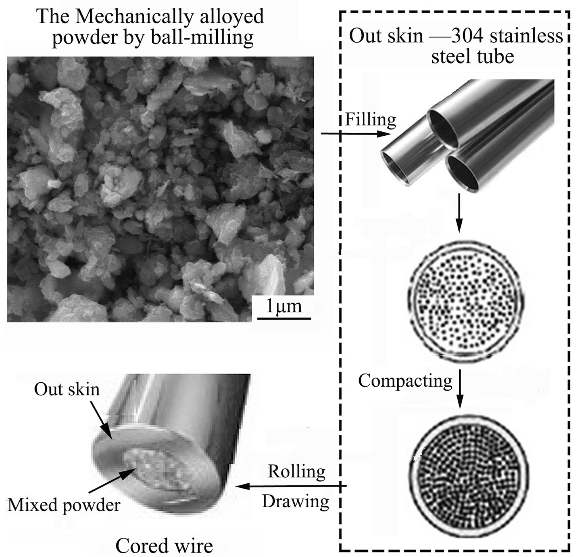
2.1. Materials

A commercial low-carbon steel plate (purchased from Honghuida Commercial and Trading Co. Ltd., Dalian, China) was cut into the dimensions of 100 mm × 100 mm × 10 mm and used as substrate. The nominal composition of the low-carbon steel is listed in Table 1. Prior to surfacing coating, the substrate was mechanically polished and followed by ultrasonic cleaning with anhydrous ethanol.
Considering the mechanical properties, low cost and low environmental impact together with good compatibility and firm combination with the substrate, a novel iron-based alloy composition based upon the Fe–(Cr, Mo)–C–(B, P) alloy system was designed in the current work. To attain the desired performance, the composition of the iron-based alloy includes smaller amounts of Chrome (Cr) to form hard fine-grained precipitates, Nickel (Ni) to form an austenitic matrix, Boron (B) to promote the formation of hard fine-grain precipitates, Molybdenum (Mo) for the secondary composition as well as Rare earth element (Re) to refine grains and purify grain boundaries. The self-designed multi-element alloys was made into flux-cored wires (FCWs) as shown in Figure 1, which has a nominal composition (at %) of 18.9 Cr, 4.2 Ni, 2.5 Si, 2.43 Mn, 1.2 Mo, 3.7 C, 19.2 B, 0.05 Re, balance Fe. Figure 1 shows the preparation process of the FCWs in detail, which consists of ball milling, filling, rolling and drawing processes. Firstly, raw powders of Fe (100 μm, 99.7% purity, the same below), Cr, Ni, Si, Mn, Mo, C, B, and Re were mechanically alloyed in a SX-2 high-energy planetary ball mill (Tianchuang Powder Technology Co. Ltd., Changsha, China). Ball milling was carried out at 270 rpm for 75 h in 0.2 wt.% ethanol as a process control agent by using a sealed cylindrical tungsten carbide vial and balls in a protecting atmosphere of Ar. The mass ratio of ball to powder was about 18:1. After milling, the mixture of the alloyed powders was filtered and dried at 100 °C for 24 h. Then, the alloyed powders were filled into the core of the thin-walled tubes made of AISI 304 stainless steel (outer skin), where the filling coefficient was about 36%. Finally, the filled tubes were processed into the cored wires with a diameter of 2.4 mm by rolling and drawing.

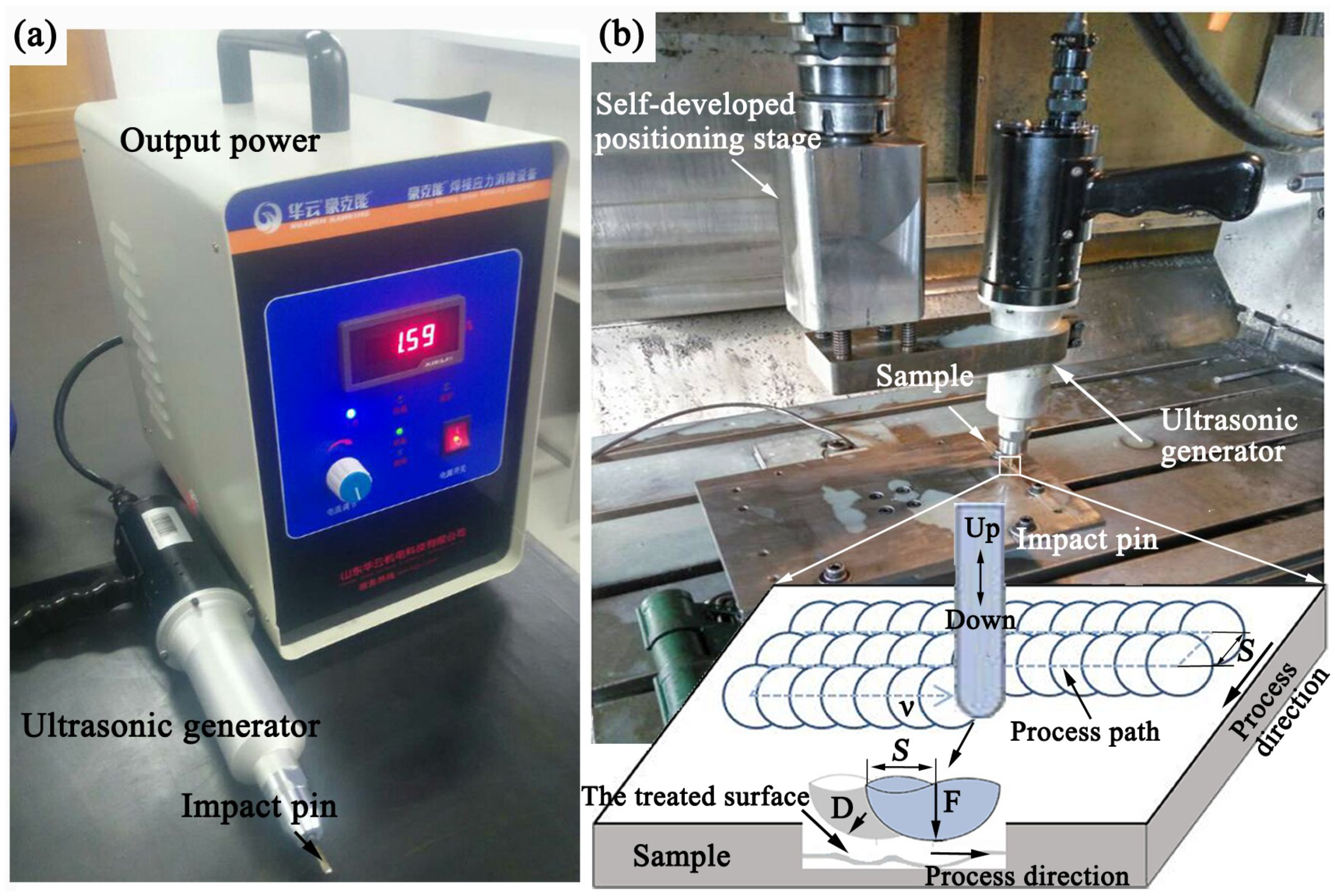
2.2. Preparation of Coating and Ultrasonic Impact Process

The iron-based alloy coating was deposited on the low carbon steel plate by manual gas tungsten arc welding (GTAW) using the prepared FCWs. The processing parameters for GTAW are listed in Table 2.
Subsequently, ultrasonic impact was conducted on the as-deposited coating by using an ultrasonic impact equipment (type: HY2050G, Huawin Electrical and Mechanical Technology Co., Ltd., Jinan, China), as shown in Figure 2a. The output power and the impact frequency for the ultrasonic impact equipment are 1.5 kW and 20 kHz, respectively. The ultrasonic generator consists of a piezo-ceramic transducer, a step-like ultrasonic horn and a tungsten carbide impact head installed on the ultrasonic horn tip. During ultrasonic impact processing, the ultrasonic generator was set on a numerical control lathe retrofitted with a self-developed tool positioning stage so that the movement of the impact head with a spherical pin could be precisely controlled. The static load was introduced through the positioning stage and the sample to be processed was constrained by the clamps fixed on the lathe bench. The impact pin directly contacts the sample surface and moves freely up and down between the horn tip and the coating surface under the combined effect of the ultrasonic waves and the static load. The detailed ultrasonic impact procedure is shown in Figure 2b. In the ultrasonic impact experiment, the impact time is constant to ensure that the entire surface to be processed of specimen could be exactly and completely covered by the impact pin. The main parameters for the ultrasonic impact process are given in Table 3.

2.3. Morphology and Microstructural Characterization

To study the cross-sectional morphology of the coatings before and after ultrasonic impact, the specimens were cut along the thickness direction of coating by wire electrical discharge machining, and manually polished to a mirror-like finish. The polished specimens were etched by the corrodent (HNO3/HCl = 1:3) for 90 s at room temperature for microstructure examination according to standard metallographic techniques. The cross-section microstructure of coating specimens was characterized by optical microscope (XP 330C, Caikon Optical instrument Co. Ltd., Shanghai, China) and scanning electron microscopy (FEI Nano Nova 450, FEI Company, Hillsboro, OR USA) equipped with energy dispersive spectroscopy (EDS) and electron backscattered diffraction (EBSD). The consisting phase of coating surface was determined using X-ray diffractometer (Rigaku D/max-2400, Rigaku Corporation, Tokyo, Japan) with Cu-Kα radiation. Meanwhile, the grain size of coating surface was also estimated by using the full width at half maximum of a specific diffraction peak obtained from the X-ray diffraction (XRD) results according to the Scherrer equation [13,20]. In addition, the chemical composition of the cross-section of coating after ultrasonic impact was assessed using EDS. Furthermore, the microstructure evolution of coating surface and near surface during the ultrasonic impact was examined by EBSD analyses.

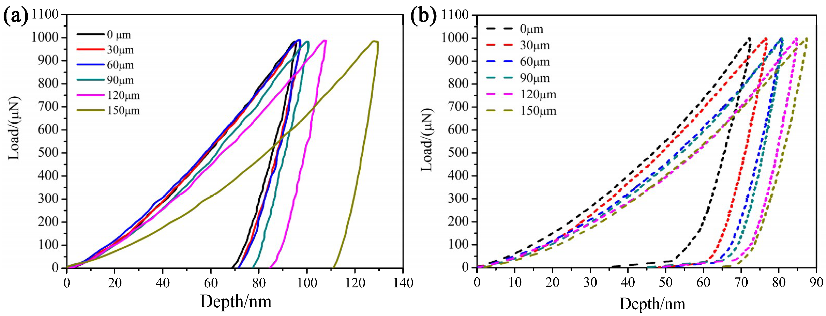
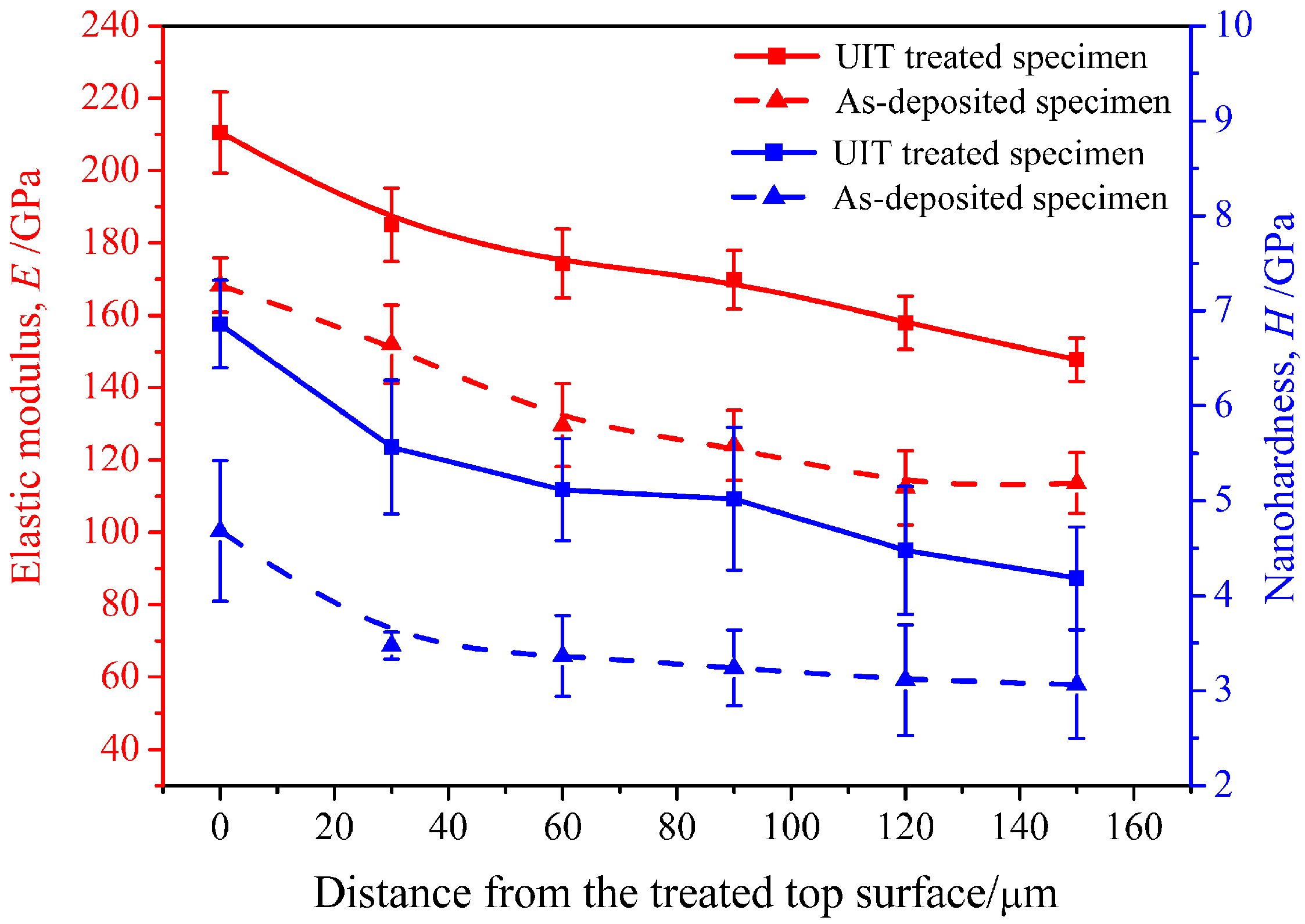
2.4. Nano-Indentation Test

To investigate the microstructural pertinent mechanical property before and after the ultrasonic impact, the micro-hardness measurements were performed on the cross-section along the thickness direction of the coating by using a nano-indenter (TI 950 Triboindenter, Hysitron Inc., Minneapolis, MN, USA). The maximum load was 1000 μN and the holding time was 20 s during the indentation test. The corresponding load–displacement curves were recorded and used to determine the micro-hardness and elastic modulus following the Oliver and Pharr method [21]. Each test was repeated five times for calculating the mean value.

2.5. Wear Tests under Oil-Lubricated Conditions

The wear performance of the coating surface was measured on a MRH-5A type wear test machine (supplied with Yihua Tribology Testing Technology Co., Ltd., Jinan, China) under oil-lubricated conditions. A standard GCr15 steel ring with an outer diameter of 48 mm and an inner diameter of 20 mm was used as the upper counterpart for friction pairs. The lower counterparts for friction pairs were the coated specimens with an outer diameter of 45 mm and inner diameter of 25 mm. Prior to each test, all specimens were polished, cleaned in an ultrasonic bath with acetone, dried in the oven at 100 °C and weighed using an electronic balance with an accuracy of 0.0001 g. When the test was conducted, the upper counterpart was fixed on the rotation shaft and it rotated together with the main shaft at a constant speed. The lower counterpart, connecting with the wheel torque sensor, which was installed on the front panel, was subjected to the load applied on its surface from the upper counterpart. As for the sliding wear test, it was performed on the appressed counterface, which located between the upper and lower counterparts. During the sliding test, the rotation of the upper counterpart was driven by a hydraulic system. When the different loads are applied, the force sensor connected with the wheel torque can record the friction torque value. The corresponding friction coefficient can be calculated according to Equation (1):
μ = T / ( p × r )
where μ is the friction coefficient, T is the friction torque (N·mm), p is the applied load and r is the radius of the counterpart (mm).
For the wear test, a constant spindle rotation speed of 380 r/min was selected under different loads of 200, 400, 600, 800, and 1000 N. The test time and temperature were 1–5 h and 25 °C, respectively. The lubricating medium used is the ordinary CD40 diesel engine oil (purchased from Jiexuan lubricants Co., Ltd., Guangzhou, China) with the density of about 0.8957 g/cm3 and the viscosity of 139.6 and 12.5 cSt at 40 and 100 °C, respectively. Then the specimens were ultrasonic cleaned, dried and weighed again after the test. Each test as a function of the applied load was repeated at least three times and the average results of three repeated test was recorded for error analysis under the same wear condition. Wear amount of specimens was quantitative according to the changes of the average wear mass. Therefore, both the friction coefficient and wear amount could be obtained. The detailed testing conditions and methods were described elsewhere [22]. Also, the morphologies of the worn surfaces were examined by the observation of SEM.

3. Results and Discussion

3.1. Morphology and Microstructure Analysis

Figure 3 shows the macro morphology and microstructure of the as-deposited coating. From the cross-section micrographs of the as-deposited coating shown in Figure 3a,b, it can be seen that the deposited coating with a dense structure is well-bonded to the substrate. No obvious pores, micro-cracks and other defects can be observed on the fusion zone and its vicinity region. A large amount of the solidification-formed coarse columnar grains appeared near the fusion zone as shown in Figure 3c.
Figure 4 shows the XRD patterns for the coatings before and after ultrasonic impact. The as-deposited coating mainly consists of the austenitic phase (γ-austenite). Furthermore, Fe–Cr intermetallic compounds as well as M2B (M = Fe, Cr, Mo) are dispersed in the austenitic matrix, which is beneficial to attain a higher surface hardness of the coating. In order to clearly clarify the effect of ultrasonic impact on the microstructure of the near-surface layer, only the main phase γ-austenite is taken into account without considering other phases and metallic compounds. For the ultrasonic impacted coating, the diffraction peaks of martensite phase can be observed in the XRD spectrum illustrated in Figure 4. The martensite phase is the deformation-induced α’-martensite phase, which is formed mainly from the plastic deformation of austenite matrix during ultrasonic impact. The similar phenomenon was reported in the literature [13]. Meanwhile, comparing with the as-deposited coating, the peak broadening for the austenitic phase was observed after ultrasonic impact, which can be mainly owing to the grain refinement and microstrain generated near the surface layer during the impact process [23,24]. In addition, the average crystallite size of the ultrasonic impacted coating surface is about 11.04 nm measured from (110) diffraction peak, which is about 38.78 nm for the as-deposited coating. It demonstrates that the microstructure of coating surface layer has been refined by ultrasonic impact.
The typical cross-sectional micrographs of the coating before and after ultrasonic impact are shown in Figure 5. It can be seen that the microstructure of the as-deposited coating is quite different from that of ultrasonic-impacted one. The as-deposited coating presents a homogeneous microstructure as shown in Figure 5a,b. However, the ultrasonic impacted coating exhibits a gradient microstructure along the thickness direction as shown in Figure 5c,d.
Moreover, in Figure 5c, it is clearly that a conspicuous plastic deformation layer is generated at a depth of approximately 80 μm from the treated top surface of the coating, and a certain amount of the deformation-induced α’-martensitic phase was formed. However, the plastic deformation layer is inhomogeneous. From the SEM micrograph image shown in Figure 5d, a thin fine grain zone with a thickness of about 34 μm beneath the treated surface can be observed in the near-surface layer. This means that the coating near-surface layer underwent a severe plastic deformation. Additionally, no obvious grain boundaries and crystallographic features can be identified clearly compared with the coarse grain zones, which are far from the top surface of coating.
Figure 6 shows the higher magnification SEM morphologies of the selected regions A and B (in Figure 5d) on the cross-section of the coating, and the corresponding EDS analysis results after ultrasonic impact. In the selected region A with a fine crystallite near the top surface as shown in Figure 6a, it is hard to distinguish the consisting phases and the grain boundaries. In the selected region B far from the treated top surface shown in Figure 6b, the grain morphology is clearly identified. This further indicates that the obvious grain refinement and severe plastic deformation occurred during the ultrasonic impact. Based on the EDS analysis results, it can be found that the concentration of elements Ni, Cr in region B is different from that in region A. This may relate to the formation of the deformation-induced α’-martensite in the ultrasonic affected zone, which may lead to the redistribution of the elements Ni, Cr, and result in different elemental content between the selected regions A and B.
Figure 7 shows EBSD observations of the microstructure micrograph and the average grain-size distribution on the cross-section of the coating near-surface layer with and without UIT processing. Here, Figure 7a,b is the EBSD inverse pole figures (IPF) superimposed by the orientation map triangle on the bottom right corner, respectively, which present the discernible differences between the two samples. Figure 7c,d is the statistical analysis between average grain size and number percentage on the cross-section of the coating near-surface layer. It is obviously that the near-surface morphology of the as-deposited and UIT-treated specimens is different. For the as-deposited coating shown in Figure 7a, the initial cross-sectional microstructure comprises the coarse austenitic grains, and the grain boundaries are basically parallel to each other with <112> preferred orientations. Meanwhile, the size of the austenitic grains is not uniform and the average grain size did not exceed 300 nm according to the histograms of grain size versus number percentage shown in Figure 7c. In the case of the UIT-treated specimen shown in Figure 7b, the cross-section microstructure of the coating near-surface layer is mainly composed of fine near-equiaxed crystals with random orientations. The average grain size of the fine equiaxed grains is smaller than 100 nm as shown in Figure 7d. This also further validates the grain size from the XRD pattern discussed above. Results indicate that the UIT can markedly improve the initial coarse austenitic microstructure of the as-deposited coating, make the bulky columnar crystals change to the fine equiaxed crystals and simultaneously change the grains orientation. Therefore, the initial grains in the coating near-surface layer have been significantly refined and the grain size reaches the nanometer scale after UIT processing.
In addition, the fine grains in the near-surface layer gradually turn into the irregular submicron grains and even reach to coarse grains with increasing the depth from the treated surface along the cross-section. This phenomenon can be explained by the fact that the plastic deformation induced by the UIT presents a gradient distribution with the highest plastic strain formed in the treated top surface and gradually decreased deeper from the coating surface.

3.2. Mechanical Properties of Surface Layer

Figure 8 exhibits the load–displacement results of the specimens before and after UIT processing. Six test points 1 to 6 are schematically shown in Figure 5d at the depths of approximately 0, 30, 60, 90, 120, and 150 μm beneath the treated surface. As can be seen, both the maximum displacement and residual displacement of the deposited and UIT treated specimens increase as the indentation location gets far from the coating surface under the maximum load of 1000 μN. Moreover, the values of maximum and residual displacements of the testing points shown in Figure 8b are less than that in the same tested position shown in Figure 8a, which indicates that the microscopic machine property especially the nanohardness of the coating near-surface is enhanced after UIT. Furthermore, the maximum and residual displacements of the near-surface layer are less than that of the deeper locations far from the treated top surface. This can be attributed to the fact that the strengthening effect of UIT tends to be weak with increasing the distance from the treated surface.
The corresponding nanohardness and elastic modulus distribution of the coating cross-section before and after UIT are shown in Figure 9. Apparently, both the nanohardness and elastic modulus of the UIT treated specimen are obviously higher than that of the as-deposited specimen under the same test conditions. The increments of the elastic modulus and hardness are well-known to favor the enhancement of the stiffness and the resistance of foreign object damage of the components [12]. Therefore, this means that the UIT can help increase the resistance of foreign object damage of the coating. The increased hardness of the UIT treated coating can be interpreted by the work-hardening effects and grain refinement on the coating surface according to the Hall-Petch relationship [25,26]. In addition, the wear behavior of materials can be evaluated in terms of the ratio between the hardness (H) and elastic modulus (E). High H/E ratio is more beneficial to attain excellent wear resistance [27]. Here, the H/E ratios of the near-surface layer before and after UIT are 0.027 and 0.033, respectively. Obviously, a higher H/E value is obtained after UIT. Therefore, it can be concluded that UIT improved the wear resistance of the deposited coating.

3.3. Wear Properties Analysis

Figure 10a,b show the friction coefficient and wear loss with the applied loads in the range of 200–1000 N at a sliding speed of 380 r/min for 1 h, respectively. It can be found that both the friction coefficient and wear loss of the specimens before and after UIT accordantly increase with increasing the applied load under the same conditions. Meanwhile, both the friction coefficient and wear loss of the UIT-treated specimen are significantly smaller than that of the as-deposited coating. It indicates that the UIT treated coating surface exhibits better wear resistance compared with the as-deposited coating. The enhancement in wear resistance maybe owing to the increase in hardness of the UIT treated surface, which is composed of the fine grains and the deformation-induced α’-martensite phase.
The wear characteristic before and after UIT process are further investigated through SEM. Figure 11 shows the worn surface micrographs subjected to the applied load of 800 N with a sliding speed of 380 r/min after 1 h. Obviously, the UIT-treated specimen (Figure 11b) shows different worn morphologies from that of the as-deposited specimen as shown in Figure 11a. For the as-deposited coating, several wide and deep wear grooves parallel to the sliding direction and some randomly distributed abrasive particles and fragments occur on the worn surface. Thus, the dominant wear mechanism for the as-deposited specimen is considered to adhesive and abrasive wear. In the case of the UIT-treated specimen, the parallel wear scars become narrower and shallower and only minor amounts of spots formed. This exhibits the typical characteristics of abrasive wear. The change of the wear mechanisms from adhesive type to abrasive type indicates that the wear resistance of the specimen is enhanced during UIT processing.
Figure 12 shows the worn micrographs subjected to the applied load of 800 N with a high sliding speed of 380 r/min after 5 h. From Figure 12a, it can be seen that the large area of peelings and spots morphologies occur on the as-deposited coating surface, indicating a strong-adhesion wear feature. In contrast, deeper and wider grooves and cracks morphologies appear on the UIT-treated surface shown in Figure 12b. Apparently, the wear failure of both specimens is more serious with time going; however, the UIT-treated specimen presents the less worn than the as-deposited specimen. This further demonstrates that the coating possesses better wear resistance after UIT, and the wear mechanism also have changed.
Both the wear characteristics and failure mode of coating have changed after UIT process according to the above-discussed experimental results. It maybe the synthetic effect of the grain refinement and the formation of the deformation-induced α’-martensite phase that benefits the increase of the surface hardness of the UIT-treated specimen during UIT. In consequence, the increased surface hardness induced by UIT will ultimately affect the wear resistance of the specimen based on the Holms and Archards wear theory [26], which is described as follows:
V = P F N / H
where V presents the wear volume loss per unit sliding distance, FN, H and P are the applied load, the hardness of the materials (here, refers to the hardness of coating surface subjected to wear) and the dimensionless wear coefficient, respectively. Therefore, the nanograined structure and the deformation-induced α’-martensite phase formed on the treated coating surface contribute to the improvement in surface strength and wear resistant properties after UIT.

4. Conclusions

In this study, a novel iron-based alloy coating has been deposited and surface nanocrystallized on a low carbon-steel substrate through the combination of argon arc overlaying and subsequent ultrasonic impact treatment (UIT) technique. The cross-section morphology of the UIT-treated coating exhibits a conspicuous gradient microstructure. A highly deformed nanocrystalline layer with the average grain size smaller than 100 nm was generated at the depth of approximately 34 μm beneath the treated surface, and the deformation-induced α’-martensite phase was also formed. After the UIT process, the UIT-treated coating shows higher H/E value, lower friction coefficient and wear loss than the as-deposited coating. All these will contribute to a significant improvement in the coating wear resistance. In addition, the wear mechanism has changed from the adhesive type of the as-deposited coating to the abrasive type of the UIT-treated coating.

Author Contributions

Conceptualization and data curation, L.L.; methodology, Y.G. and H.G.; resources, N.Z., Y.G. and H.G.; supervision, S.Z. and N.Z.; validation and writing—original draft, L.L.; writing—review and editing, L.L., S.Z. and N.Z.

Funding

This research received no external funding.

Conflicts of Interest

The authors declare no conflict of interest.

References

  1. Pereira, D.; Gandra, J.; Pamies-Teixeira, J.; Miranda, R.M.; Vilaca, P. Wear behaviour of steel coatings produced by friction surfacing. J. Mater. Process. Technol. 2014, 214, 2858–2868. [Google Scholar] [CrossRef]
  2. Gholipour, A.; Shamanian, M.; Ashrafizadeh, F. Microstructure and wear behavior of stellite 6 cladding on 17-4 PH stainless steel. J. Alloy Compd. 2011, 509, 4905–4909. [Google Scholar] [CrossRef]
  3. Puli, R.; Ram, G.D.J. Corrosion performance of AISI 316L friction surfaced coatings. Corros. Sci. 2012, 62, 95–103. [Google Scholar] [CrossRef]
  4. Santacruz, G.; Takimi, A.S.; Camargo, F.V.; Bergmann, C.P.; Fragassa, C. Comparative study of jet slurry erosion of martensitic stainless steel with tungsten carbide HVOF coating. Metals 2019, 9, 600. [Google Scholar] [CrossRef]
  5. Li, J.H.; Kong, D.J. Micro-structures and high-temperature friction-wear performances of laser cladded Cr–Ni coatings. Materials 2018, 11, 137. [Google Scholar]
  6. Heidarshenas, B.; Hussain, G.; Asmael, M.B.A. Development of a TiC/Cr23C6 composite coating on a 304 stainless steel substrate through a tungsten inert gas process. Coatings 2017, 7, 80. [Google Scholar] [CrossRef]
  7. Shi, S.H.; Xu, A.Q.; Fan, J.W.; Wei, H.P. Study of cobalt-free, Fe-based alloy powder used for sealing surfaces of nuclear valves by laser cladding. Nucl. Eng. Des. 2012, 245, 8–12. [Google Scholar] [CrossRef]
  8. Milanti, A.; Koivuluoto, H.; Vuoristo, P.; Bolelli, G.; Bozza, F.; Lusvarghi, L. Microstructural characteristics and tribological behavior of HVOF-sprayed novel Fe-based alloy coatings. Coatings 2014, 4, 98–120. [Google Scholar] [CrossRef]
  9. Sun, Z.; Retraint, D.; Baudin, T.; Helbert, A.L.; Brisset, F.; Chemkhi, M.; Zhou, J.; Kanouté, P. Experimental study of microstructure changes due to low cycle fatigue of a steel nanocrystallised by Surface Mechanical Attrition Treatment (SMAT). Mater. Charact. 2017, 124, 117–121. [Google Scholar] [CrossRef]
  10. Bagherifard, S.; Slawik, S.; Fernández-Pariente, I.; Pauly, C.; Mücklich, F.; Guagliano, M. Nanoscale surface modification of AISI 316L stainless steel by severe shot peening. Mater. Des. 2016, 102, 68–77. [Google Scholar] [CrossRef]
  11. Bleicher, F.; Lechner, C.; Habersohn, C.; Kozeschnik, E.; Adjassoho, B.; Kaminski, H. Mechanism of surface modification using machine hammer peening technology. CIRP Ann. 2012, 61, 375–378. [Google Scholar] [CrossRef]
  12. Luo, K.Y.; Lu, J.Z.; Zhang, Y.K.; Zhou, J.Z.; Zhang, L.F.; Dai, F.Z.; Zhang, L.; Zhong, J.W.; Cui, C.Y. Effects of laser shock processing on mechanical properties and micro-structure of ANSI 304 austenitic stainless steel. Mater. Sci. Eng. A 2011, 528, 4783–4788. [Google Scholar] [CrossRef]
  13. Yang, X.; Wang, X.; Ling, X.; Wang, D.X. Enhanced mechanical behaviors of gradient nano-grained austenite stainless steel by means of ultrasonic impact treatment. Results Phys. 2017, 7, 1412–1421. [Google Scholar] [CrossRef]
  14. Gao, H.; Dutta, R.K.; Huizenga, R.M.; Amirthalingam, M.; Hermans, M.J.M.; Buslaps, T.; Richardson, I.M. Stress relaxation due to ultrasonic impact treatment on multi-pass welds. Sci. Technol. Weld. Join. 2014, 19, 505–513. [Google Scholar] [CrossRef]
  15. Liu, C.; Ge, Q.; Chen, D.; Gao, F.; Zou, J.S. Residual stress variation in a thick welded joint after ultrasonic impact treatment. Sci. Technol. Weld. Join. 2016, 21, 624–631. [Google Scholar] [CrossRef]
  16. Yu, Y.X.; He, B.L.; Liu, J.; Chen, Z.X.; Man, H. Surface plastic deformation and nanocrystallization mechanism of welded joint of 16MnR steel treated by ultrasonic impact. Mater. Sci. 2015, 21, 612–615. [Google Scholar] [CrossRef]
  17. He, B.L.; Xiong, L.; Jiang, M.M.; Yu, Y.Y.; Li, L. Surface grain refinement mechanism of SMA490BW steel cross joints by ultrasonic impact treatment. Int. J. Miner. Metall. Mater. 2017, 24, 410–414. [Google Scholar] [CrossRef]
  18. He, B.; Deng, H.; Jiang, M.; Wei, K.; Li, L. Effect of ultrasonic impact treatment on the ultra high cycle fatigue properties of SMA490BW steel welded joints. Int. J Adv. Manuf. Technol. 2018, 96, 1571–1577. [Google Scholar] [CrossRef]
  19. Zhang, H.; Wang, D.; Xia, L.; Lei, Z.Y.; Li, Y.Z. Effects of ultrasonic impact treatment on pre-fatigue loaded high-strength steel welded joints. Int. J. Fatigue 2015, 80, 278–287. [Google Scholar] [CrossRef]
  20. Monshi, A.; Foroughi, M.R.; Monshi, M.R. Modified Scherrer equation to estimate more accurately nano-crystallite size using XRD. World J. Nano Sci. Eng. 2012, 2, 154–160. [Google Scholar] [CrossRef]
  21. Huang, H.F.; Li, J.J.; Li, D.H.; Liu, R.D.; Lei, G.H.; Huang, Q.; Yan, L. TEM, XRD and nanoindentation characterization of Xenon ion irradiation damage in austenitic stainless steels. J. Nucl. Mater. 2014, 454, 168–172. [Google Scholar] [CrossRef]
  22. Zhou, X.; Li, L.; Wen, D.; Liu, X.X.; Wu, C.W. Effect of hybrid ratio on friction and wear behavior of AZ91D matrix nanocomposites under oil lubricated conditions. Trans. Nonferrous Met. Soc. China 2018, 28, 440–450. [Google Scholar] [CrossRef]
  23. Yasuoka, M.; Wang, P.; Zhang, K.; Qiu, Z.Y.; Kusaka, K.; Pyoun, Y.S.; Murakami, R. Improvement of the fatigue strength of SUS304 austenite stainless steel using ultrasonic nanocrystal surface modification. Surf. Coat. Technol. 2013, 218, 93–98. [Google Scholar] [CrossRef]
  24. Wang, H.; Song, G.; Tang, G. Effect of electropulsing on surface mechanical properties and microstructure of AISI 304 stainless steel during ultrasonic surface rolling process. Mater. Sci. Eng. A 2016, 662, 456–467. [Google Scholar] [CrossRef]
  25. Amanov, A.; Penkov, O.V.; Pyun, Y.S.; Kim, D.E. Effects of ultrasonic nanocrystalline surface modification on the tribological properties of AZ91D magnesium alloy. Tribol. Int. 2012, 54, 106–113. [Google Scholar] [CrossRef]
  26. He, B.; Yu, Y.; Xia, S.; Lv, Z.M. Effect of ultrasonic impact treating on wear resistance and microhardness of AZ91D magnesium alloy. Rare Met. Mater. Eng. 2017, 46, 17–22. [Google Scholar]
  27. Leyland, A.; Matthews, A. On the significance of the H/E ratio in wear control: A nanocomposite coating approach to optimised tribological behaviour. Wear 2000, 246, 1–11. [Google Scholar] [CrossRef]
Figure 1. Preparation of the flux cored-wires by using the alloyed powders.
Coatings 09 00804 g001
Figure 2. (a) Apparatus for ultrasonic impact; (b) the schematic of ultrasonic impact processing.
Coatings 09 00804 g002
Figure 3. Macro morphologies and cross-sections microstructure of the as-deposited coating: (a) Macro morphologies of coating and interface between coating and substrate; (b) magnified optical microstructure; (c) SEM image of the region A selected in (a).
Coatings 09 00804 g003
Figure 4. XRD patterns for the as-deposited and ultrasonic-impacted coatings.
Coatings 09 00804 g004
Figure 5. Typical cross-sectional images of coatings: (a) OM and (b) SEM images of coating before ultrasonic impact; (c) OM and (d) SEM micrographs of coating after ultrasonic impact.
Coatings 09 00804 g005
Figure 6. Higher magnification SEM morphologies and EDS analysis results in the selected regions in Figure 5d: (a) Region A; (b) region B.
Coatings 09 00804 g006
Figure 7. Cross-sectional EBSD microstructure and grain-size distribution in the near-surface of specimens. Inverse pole figure (IPF) maps: (a) The as-deposited specimen; (b) the UIT-treated specimen. The histograms of grain-size versus the corresponding number percentage in the near surface: (c) The as-deposited specimen; (d) the UIT-treated specimen.
Coatings 09 00804 g007
Figure 8. Measured load–displacement curves along the coating cross-section: (a) Sample before UIT; (b) sample after UIT.
Coatings 09 00804 g008
Figure 9. Profiles of the cross-sectional nanohardness and elastic modulus before and after UIT.
Coatings 09 00804 g009
Figure 10. Variations in: (a) The friction coefficient; (b) wear mass with the applied load before and after UIT.
Coatings 09 00804 g010
Figure 11. Worn morphologies of the specimens with the applied load of 800 N at a sliding speed of 380 r/min after 1 h: (a) The as-deposited coating; (b) the UIT-treated coating.
Coatings 09 00804 g011
Figure 12. Worn morphologies of specimens at the applied load of 800 N with a sliding speed of 380 r/min for 5 h: (a) The as-deposited coating; (b) the UIT-treated coating.
Coatings 09 00804 g012
Table 1. Chemical composition of the low-carbon steel.
ElementCMnNiCrMoFe
Content (wt.%)≤0.10.260.0100.016≤0.005Bal.
Table 2. Processing parameters for GTAW.
ParameterCondition
Power polarityDirect current straight polarity (DCSP)
Gas flow (L/min)12−15
Welding current (A)140−160
Tungsten electrode diameter (mm)3.2
Inter-pass temperature (°C)100−150
Welding speed (mm/min)80−120
Table 3. The main parameters for the ultrasonic impact process.
Tip Diameter D/(mm)Static Load F/(kg)Number of Vibration Strike per∙mm2Amplitude/(μm)Step Distance S/(mm)Feeding Rate ν/(mm/min)Impact Current/(A)
21058246300.0110001.4–1.6

