Article

Large-Area Laying of Soft Textile Power Generators for the Realization of Body Heat Harvesting Clothing

Department of Mechanical and Aerospace Engineering, Chung-Cheng Institute of Technology, National Defense University, No.75, Shiyuan Rd., Daxi Dist., Taoyuan City 33551, Taiwan
*
Author to whom correspondence should be addressed.
Coatings 2019, 9(12), 831; https://doi.org/10.3390/coatings9120831
Submission received: 31 October 2019 / Revised: 28 November 2019 / Accepted: 3 December 2019 / Published: 6 December 2019
(This article belongs to the Special Issue Thin Films for Thermoelectric Applications)

Abstract

:
This paper presents the realization of a flexible thermoelectric (TE) generator as a textile fabric that converts human body heat into electrical energy for portable, low-power microelectronic products. In this study, an organic non-toxic conductive coating was used to dip rayon wipes into conductive TE fabrics so that the textile took advantage of the TE currents which were parallel to the temperature gradient. To this end, a dyed conductive cloth was first sewn into a TE unit. The TE unit was then sewn into an array to create a temperature difference between the human body and the environment for TE power harvesting. The prototype of the TE fabric consisted of 48 TE units connected by conductive wire over an area of 275 × 205 mm2, and the TE units were sewn on a T-shirt at the chest area. After fabrication and property tests, a Seebeck coefficient of approximately 20 μV/K was measured from the TE unit, and 0.979 mV voltage was obtained from the T-shirt with TE textile fabric. Since the voltage was generated at a low temperature gradient environment, the proposed energy solution in actual fabric applications is suitable for future portable microelectronic power devices.

1. Introduction

The demand for portable and flexible electronic devices is increasing due to the growth in Internet of Things (IoT) products. Therefore, flexible thermoelectric generator (TEG) films that harvest energy from human body heat [1] have attracted considerable attention because this new technology offers a possible alternative to the current battery technology used in portable and low-power IoT devices, such as healthcare sensors and personal mobile devices [2,3]. Processes for manufacturing flexible, thin-film TEGs include thermal evaporation [4], dispenser printing [5], screen printing [6], inject printing [7], sputtering [8], and ETH Zurich has fabricated flexible TEG films through electrochemical deposition [9]. In addition, Yue [10] and Tsai [11] have summarized the TE properties of various conductive poly(3,4-ethylenedioxythiophene) (PEDOT)-based TE products, and Norris et al. [12] developed nanowire TE modules for future flexible TEGs.
Although flexible TEGs can be manufactured through various processes [13,14,15,16,17,18,19,20,21,22], each of the aforementioned conventional technologies has limitations such as cost, toxicity, complicated processes, yield issues on products, and difficulty in integrating with actual clothing. Furthermore, the power of TEGs from the conventional processes is restricted by the small generator size. In this study, we propose a simple and relatively inexpensive coating process for TE fabric fabrication. Although a good TE property for a toxic TE fabric has been reported [16], it emphasizes that the current TE fabric design was made from non-toxic material. As a TE array can be formed by the flexible fabric unit, a cloth with a TE generator can be built in a relatively large area through our proposed methodology.

2. Materials and Method

2.1. Materials

The items used for the TE fabric manufacturing included the Clevios PH500 conductive coating PEDOT: PSS (poly(3,4-ethylenedioxythiophene) polystyrene sulfonate) solution, purchased from H.C. Starck with a conductivity of 300 S/cm, and cleanroom wiper (LT Scientific model LTK2010TS, LT Scientific Inc., Baku, Khodjali Pr., Azerbaijan), 0.5 mm thick with a surface area of 230 × 230 mm2. Both the aforementioned items were connected with silver-plated wires to complete the circuit connection, and the single-core silver-plated wire was labeled Vectech Kynar AWG 32.

2.2. Instruments and Equipment

Two multimeters (Keithley Model 2000, Keithley Instruments, Solon, Ohio, USA and Fluke Model 45, Fluke Corporation, Everett, DC, USA) were used to measure the voltage and resistance of the test samples, and Fluke’s thermocouple thermometer was used for temperature measurements. In addition, a forward-looking infrared thermal image camera was used to obtain the complete temperature distribution of the TE fabric samples. A LEO supra35 scanning electron microscope was used to analyze the surface conditions of the TE sample. A self-developed measurement apparatus was used for determining the Seebeck coefficients of the flexible thin-film TE devices.

2.3. Sample Preparation

We first inserted a cleanroom wiper (230 × 230 mm2) into a 250 mL polyethylene (PE) bottle. Then, 20 mL of PH500 conductive solution was poured into the bottle for dyeing. After closing the lid, we shook the PE bottle until the wiper was fully wetted by the conductive solution. A pair of tweezers was used to remove the wiper that had been dyed with the conductive solution in the PE bottle. The wiper was then put into an oven and baked at 80 °C for 1 h, and the white wiper became gray.
After wiper preparation, we cut the wiper into a long strip with a length of 210 mm and width of 30 mm. Thus, the wiper was a long strip of 7 square units as displayed in Figure 1a. Each strip was next sewn with five overlapping layers (Figure 1b) as a TE unit. Consequently, only the central five TE layers participated in the generation of the Seebeck voltage, and the TE layers on the top and bottom did not contribute to the Seebeck voltage generation.
Figure 2a is a photo for a TE unit. The top side and bottom side of the TE unit were unsewn at the beginning, and both the top and bottom side had small lengths of unsewn fabric to which the conductive wires were sewn in the next step. It was noted that the unsewn portions on the top and bottom were interlaced weaving by conductive wires for current extraction from the TE unit. Therefore, the top and bottom layers of the TE unit were equivalent to general conductive wire. As the temperature difference was applied to the TE unit, only the middle five layers of the seven TE layers contributed to the Seebeck voltage.
After TE units were prepared, the next step involved sewing the TE units into an ordinary T-shirt. Because the chest is a large and flat area of the human body, it is suitable for the new TE clothing sewn with TE units, and a total of 48 sets of TE units were arranged in the chest area of the T-shirt as depicted in Figure 2b. Figure 2b shows the arrangement of TE units which featured eight sets horizontally and six sets vertically, and each TE unit had a length of 30 mm and a width of 30 mm with 3.5 mm thickness. Therefore, a 5 mm gap was left between each set of TE units to avoid direct electrical contact among them. Furthermore, the 48 TE units displayed in Figure 3a were sewn using traditional sewing onto the chest of the T-shirt. Since each TE unit was connected in series with conductive wires, a TE T-shirt with 48 TE units on the chest area was finally made.

3. Result and Discussion

Figure 3a displays a photo of a TE T-shirt on the human body. The chest area was estimated to occupy almost 20% of the entire T-shirt surface on both sides. Sewing additional TE units onto the entire T-shirt would increase the area available for TE units by five times. Thus, a considerably higher output power would be obtained from the TE suit. Figure 3b is a thermal image of the TE T-shirt on the chest area.
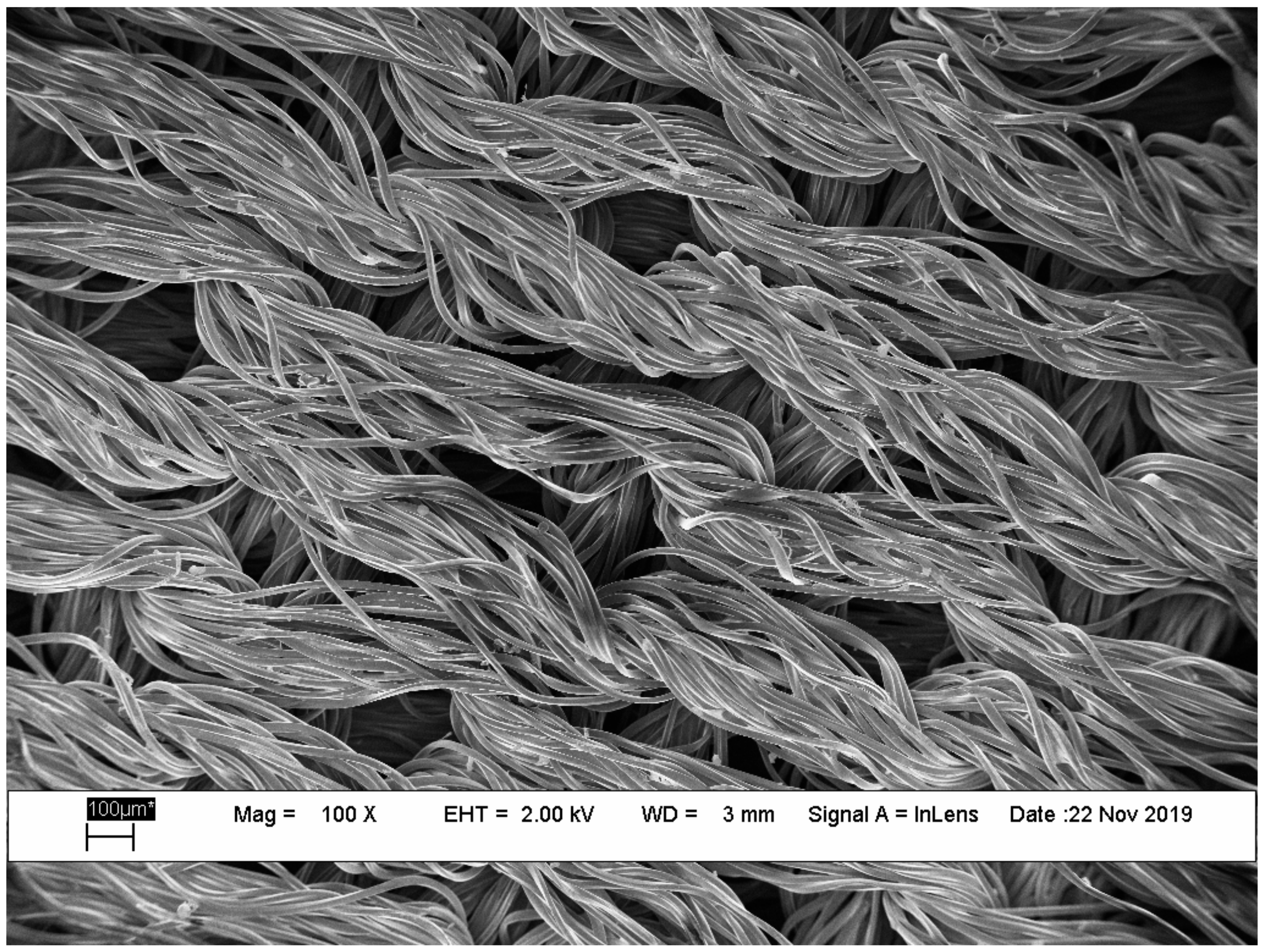
The scanning electron microscopy (SEM) images in Figure 4 depict pieces of the fabric in the cleanroom wiper. Because the TE fabric was coated with conductive polymer, coating with evaporated metal was unnecessary for conduction. No impurity particles were observed in the figures because coating was performed with water-soluble TE solvent, so that excellent overall coverage of the solvent was observed.
To calculate the electrical conductivity of the TE unit, we prepared a set of additional long TE strips cut from a TE wiper, and the strip was composed of seven rectangular units that were each 30 mm long and 30 mm wide. After conducting wires were sewn onto both sides of a small rectangle of cloth, as displayed in Figure 5, the resistance of the unit was measured. Consequently, the electrical conductivity σ of the unit was calculated to be 2.08 × 10⁻⁴ S/cm or 2.08 × 10⁻⁶ S/m through the simple equation R = ρl/A, where R is the resistance, ρ is the resistivity, l is the length, and A is the area of the cross-section. After deriving the resistivity, the conductivity of the material was next calculated according to σ = 1/ρ.
For Seebeck coefficient extraction, a 30 mm square test sample was measured and a 0.65 mV Seebeck voltage was obtained, as the temperature difference between the hot and cold sides tended toward 32 °C. Therefore, the resulting Seebeck coefficient was calculated to be 20.3 μV/K, and the power factor (PF) of a single unit was calculated to be 8.57 × 10⁻¹⁵ Wm−1K−2 or 8.57 × 10⁻⁹ μWm−1K−2 using the equation PF = α2 σ, where α and σ are the Seebeck coefficient and the conductivity, respectively.
For a single TE unit, the relationship between the Seebeck coefficient and the temperature difference was next measured. As Figure 6a presents, the hot side was in contact with the heating platform, and the cold side remained in an indoor environment without temperature control. The probes of temperature sensors were inserted into the two points between the first and second layers, and between the sixth and seventh layers of the TE unit under test, respectively.
The graph in Figure 6b plots the Seebeck voltage with temperature difference for a single TE unit. The blue curve in Figure 6b exhibits a linear positive correlation, and it stands for the TE unit with stable linear Seebeck voltage output at low temperature difference operation.
The brown curve in Figure 6b presents the measured Seebeck coefficient under temperature difference for the TE unit. When the temperature difference was less than 5 °C, the Seebeck coefficient reached 15 μV/K. As the temperature difference was only 1–2 °C, the coefficient exceeded 20 μV/K. Since the TE unit generated Seebeck voltages at relatively small temperature differences, the TE unit exhibits the higher TE conversion efficiency for low temperature differences so that it is highly suitable for wearable TE conversion.
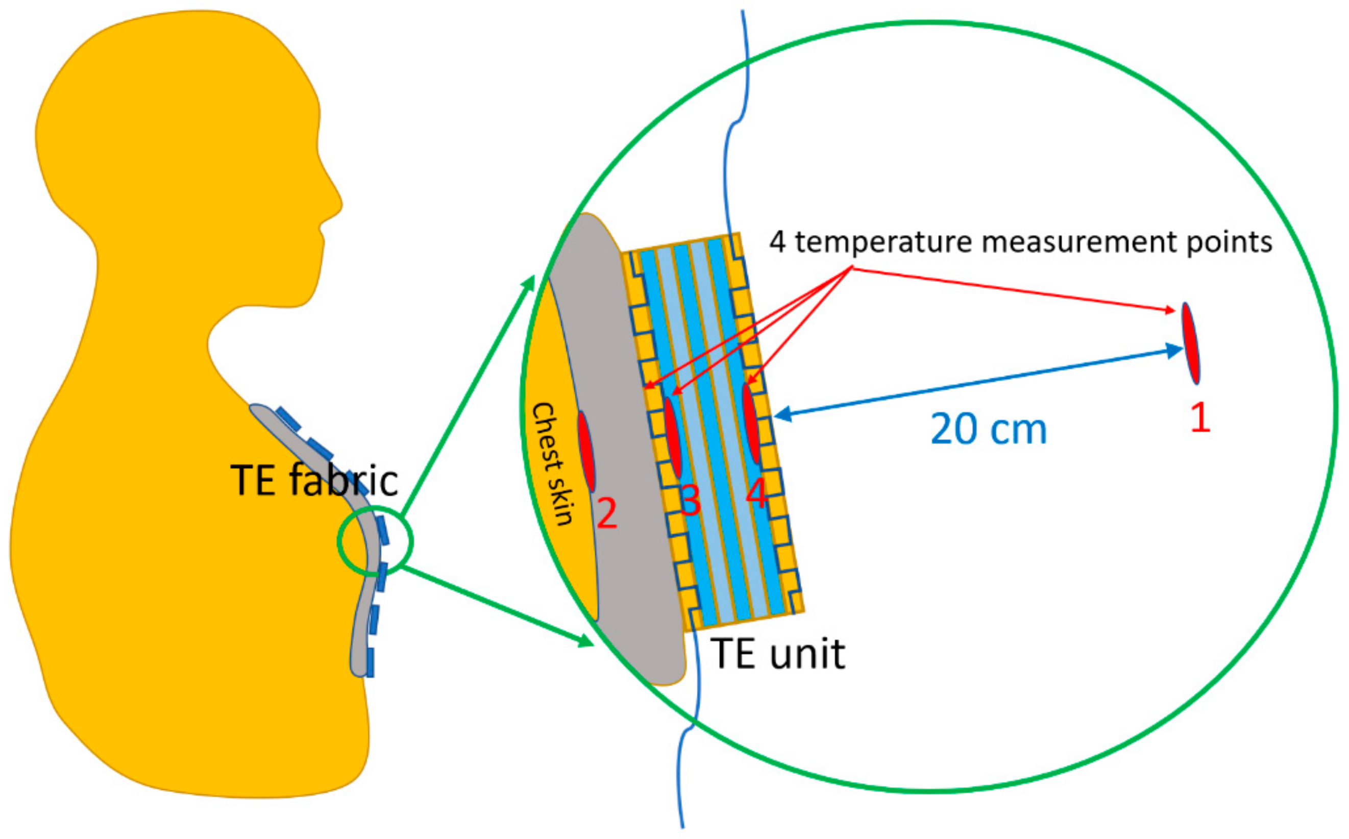
Figure 7 displays the four temperature measurement points consisting of thermocouples. As the figure shows, the first temperature measurement point was positioned 20 cm away from the chest. For the second point, tape was used to attach the probe to the chest skin. Probes for the third and fourth points were positioned at a TE unit in the middle of the chest area to measure the temperature difference between the top and bottom sides of the TE unit. Note that the third and fourth points were located between the first and second layers and between the sixth and seventh layers of the TE unit, respectively.
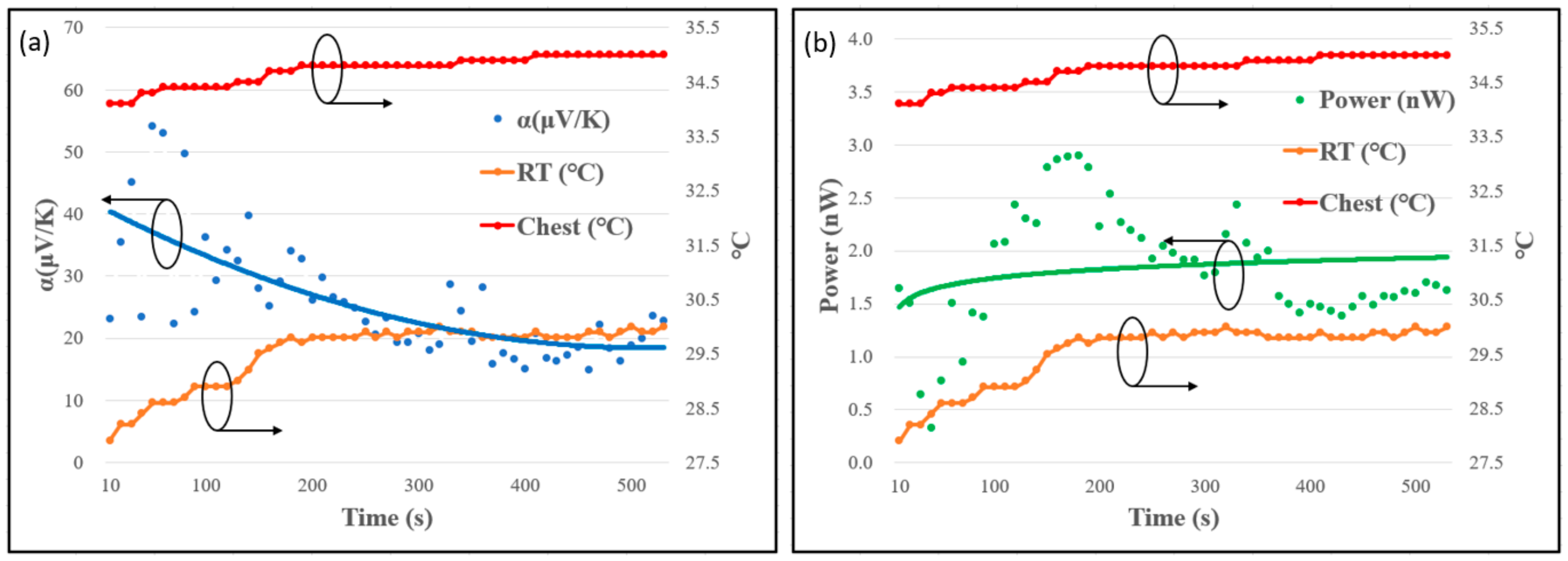
Figure 8 displays the transient TE properties of the T-shirt to present the performance of the T-shirt in an actual application. During the experiment, the temperature of the human chest also changed marginally due to the changes in the ambient temperature. Initially, when the room temperature (RT) was lower, the temperature difference between the room temperature and the chest temperature was approximately 6 °C. At this time, the thermoelectric performance of a single TE unit could be converted to a value of 40 μV/K. As the room temperature increased, the Seebeck coefficient was maintained at approximately 20 μV/K, when the difference between the room temperature and the chest temperature was only 5 °C.
To simulates the human interfering with the movement of the wearer, we first measured the total series resistance of the TE units in a static state and 338 ± 9 kΩ was obtained. Another experimental condition to simulate body movement, moving the hands, makes the TE fabric stretched during exercise, and the total series resistance can be increased to 481 ± 24 kΩ due to the telescopic pull between the sewn wire and the TE unit. Therefore, the experiments provided an average resistance of 10 KΩ for each TE unit.
The output power of the TE T-shirt can be calculated using the equation P = VI = V2/R, where resistance R was measured previously. Figure 8b displays the output power with the room and body temperatures. As the experiment reached a stable situation, the maximum Seebeck voltage of 0.979 mV was produced.
Although the stable temperature difference between the room (29.8 °C) and the chest (34.7 °C) was 4.9 °C, the temperature difference between the upper and lower layers of the TE unit measured 0.6 °C only. However, about 2.0 × 10⁻⁶ mW of power was generated by the TE T-shirt in such a low temperature difference situation.
Because the TE units are thick enough to create temperature differences for TE power generation, the TE currents are parallel to the temperature gradient for the proposed energy solution. As a result, the TE T-shirt performance can be improved by adding TE layers on each TE unit because higher voltage and higher power can be obtained from higher temperature differences between the top and bottom TE layers in a TE unit. In addition, it is expected to generate several times the total voltage and power if more flexible fabric TE units in clothing can be created. Therefore, the proposed energy solution is thus suitable for future portable microelectronic devices.
Although flexible TE films with good TE properties are available in the literature [18,19,20,21,22], the extremely thin and expansive films restrict their actually application. In this study, we successfully made 3.5 mm thick flexible and non-toxic TE units to create temperature differences for power generation through harvesting human body heat. However, the actual fabricated sample had a large series resistance which restricted power generation. Our future work will focus on the development of a low resistance device such as by optimizing the materials and studying the long-term preservation issues.

4. Conclusions

This study fabricated a prototype of a non-toxic and flexible TE generator with 48 PEDOT: PSS solution-coated TE units on a typical T-shirt. The proposed technology takes advantage of a low-cost process, parallel thermal and electrical flow, and large TE power-generation areas to produce a system that is suitable to be worn on the body. For a single TE unit, the measurements yielded for the test sample were an electrical conductivity of 2.08 × 10⁻⁶ S/m and a power factor of 8.57 × 10⁻⁹ μWm−1K−2. In the study, the difference between room temperature and chest temperature was 4.9 °C with only a 0.6 °C difference between TE devices, and the maximum Seebeck voltage of the TE fabric chain reached 0.979 mV with 2.0 × 10⁻⁶ mW output power. Because a TEG for harvesting human body heat uses small temperature differences, the aforementioned experimental data demonstrated the feasibility of the proposed TEG design.

Author Contributions

Formal Analysis, Investigation, Writing—Original, Draft Preparation, Y.-S.C.; Writing—Review and Editing, B.-J.L.

Funding

The authors would like to thank the Ministry of Science and Technology of Taiwan, R.O.C., for financial support under Grant MOST 106-2221-E-606-004.

Conflicts of Interest

The authors declare no competing interests.

References

  1. Park, H.J.; Kim, D.G.; Eom, Y.M.; Dimuthu, W.; Kim, W. Flexible thermoelectric system based on inorganic bulk materials. In Journal of Physics: Conference Series; IOP Publishing: Bristol, UK, 2018; p. 012134. [Google Scholar]
  2. Leonov, V. Thermoelectric energy harvesting of human body heat for wearable sensors. IEEE Sens. J. 2013, 13, 2284–2291. [Google Scholar] [CrossRef]
  3. Siddique, A.R.M.; Mahmud, S.; Van Heyst, B. A review of the state of the science on wearable thermoelectric power generators (TEGs) and their existing challenges. Renew. Sustain. Energy Rev. 2017, 73, 730–744. [Google Scholar] [CrossRef]
  4. Lin, J.M.; Chen, Y.C.; Lin, C.P. Annealing effect on the thermoelectric properties of Bi2Te3 thin films prepared by thermal evaporation method. J. Nanomater. 2013, 2013, 1. [Google Scholar]
  5. Chen, A.; Madan, D.; Mahlstedt, B.T.; Wrigut, P.K.; Evans, J.W. Dispenser-printed thick film thermoelectric materials. In Proceedings of the PowerMEMS, Leuven, Belgium, 30 November–3 December 2010; pp. 223–226. [Google Scholar]
  6. Cao, Z.; Koukharenko, E.; Torah, R.N.; Beeby, S.P. Exploring screen printing technology on thermoelectric energy harvesting with printing copper-nickel and bismuth-antimony thermocouples. In Proceedings of the 2013 Transducers & Eurosensors XXVII: The 17th International Conference on Solid-State Sensors, Actuators and Microsystems (TRANSDUCERS & EUROSENSORS XXVII), Barcelona, Spain, 16–20 June 2013; IEEE: Piscataway, NJ, USA, 2013; pp. 478–481. [Google Scholar]
  7. Jiao, F.; Di, C.; Sun, Y.; Sheng, P.; Xu, W.; Zhu, D. Inkjet-printed flexible organic thin-film thermoelectric devices based on p-and n-type poly (metal 1, 1, 2, 2-ethenetetrathiolate) s/polymer composites through ball-milling. Philos. Trans. R. Soc. A Math. Phys. Eng. Sci. 2014, 372, 20130008. [Google Scholar] [CrossRef] [PubMed] [Green Version]
  8. Weber, J.; Potje-Kamloth, K.; Haase, F.; Detemple, P.; Volklein, F.; Doll, T. Coin-size coiled-up polymer foil thermoelectric power generator for wearable electronics. Sens. Actuators A Phys. 2006, 132, 325–330. [Google Scholar] [CrossRef]
  9. Glatz, W.; Schwyter, E.; Durrer, L.; Hierold, C. Bi2Te3-Based Flexible Micro Thermoelectric Generator with Optimized Design. J. Microelectromechanical Syst. 2009, 18, 763–772. [Google Scholar] [CrossRef]
  10. Yue, R.; Xu, J. Poly (3, 4-ethylenedioxythiophene) as promising organic thermoelectric materials: A mini-review. Synth. Met. 2012, 162, 912–917. [Google Scholar] [CrossRef]
  11. Tsai, T.-C.; Chang, H.-C.; Chen, C.-H.; Whang, W.-T. Widely variable Seebeck coefficient and enhanced thermoelectric power of PEDOT: PSS films by blending thermal decomposable ammonium formate. Org. Electron. 2011, 12, 2159–2164. [Google Scholar] [CrossRef]
  12. Norris, K.J.; Garrett, M.P.; Zhang, J.; Coleman, E.; Tompa, G.S.; Kobayashi, N.P. Silicon nanowire networks for multi-stage thermoelectric modules. Energy Convers. Manag. 2015, 96, 100–104. [Google Scholar] [CrossRef]
  13. Tan, R.; Yang, X.; Shen, Y. Robot-aided electrospinning toward intelligent biomedical engineering. Robot. Biomim. 2017, 4, 17. [Google Scholar] [CrossRef] [PubMed] [Green Version]
  14. Sarabi, G.A.; Latifi, M.; Bagherzadeh, R. Align and random electrospun mat of PEDOT: PSS and PEDOT: PSS/RGO. AIP Conf. Proc. 2018, 1920, 020045. [Google Scholar] [CrossRef]
  15. Cheng, H.; Du, Y.; Wang, B.; Mao, Z.; Xu, H.; Zhang, L.; Zhong, Y.; Jiang, W.; Wang, L.; Sui, X. Flexible cellulose-based thermoelectric sponge towards wearable pressure sensor and energy harvesting. Chem. Eng. J. 2018, 338, 1–7. [Google Scholar] [CrossRef]
  16. Kim, M.K.; Lee, S.; Kim, C.; Kim, Y.-J. Wearable thermoelectric generator for harvesting human body heat energy. Smart Mater. Struct. 2014, 23, 105002. [Google Scholar] [CrossRef]
  17. Novak, T.G.; Kim, K.; Jeon, S. 2D and 3D nanostructuring strategies for thermoelectric materials. Nanoscale 2019, 11, 19684–19699. [Google Scholar] [CrossRef] [PubMed]
  18. Paul, B.; LuPer, J.; Eklund, P. Nanostructural tailoring to induce flexibility in thermoelectric Ca3Co4O9 thin films. ACS Appl. Mater. Interfaces 2017, 9, 25308–25316. [Google Scholar] [CrossRef] [PubMed] [Green Version]
  19. Liang, J.; Wang, T.; Qiu, P.; Yang, S.; Ming, C.; Chen, H.; Song, Q.; Zhao, K.; Wei, T.-R.; Ren, D.; et al. Flexible thermoelectrics: From silver chalcogenides to full-inorganic devices. Energy Environ. Sci. 2019, 12, 2983–2990. [Google Scholar] [CrossRef]
  20. Yang, C.; Souchay, D.; Kneiß, M.; Bogner, M.; Wei, H.M.; Lorenz, M.; Oeckler, O.; Benstetter, G.; Fu, Y.Q.; Grundmann, M.; et al. Transparent flexible thermoelectric material based on non-toxic earth-abundant p-type copper iodide thin film. Nat. Commun. 2017, 8, 16076. [Google Scholar] [CrossRef] [PubMed]
  21. Lin, Z.; Hollar, C.; Kang, J.S.; Yin, A.; Wang, Y.; Shiu, H.-S.; Huang, Y.; Hu, Y.; Zhang, Y.; Duan, X.; et al. A Solution Processable High-Performance Thermoelectric Copper Selenide Thin Film. Adv. Mater. 2017, 29, 1606662. [Google Scholar] [CrossRef] [PubMed]
  22. Varghese, T.; Dun, C.; Kempf, N.; Saeidi-Javash, M.; Karthik, C.; Richardson, J.; Hollar, C.; Estrada, D.; Zhang, Y. Flexible Thermoelectric Devices of Ultrahigh Power Factor by Scalable Printing and Interface Engineering. Adv. Funct. Mater. 2019. [Google Scholar] [CrossRef]
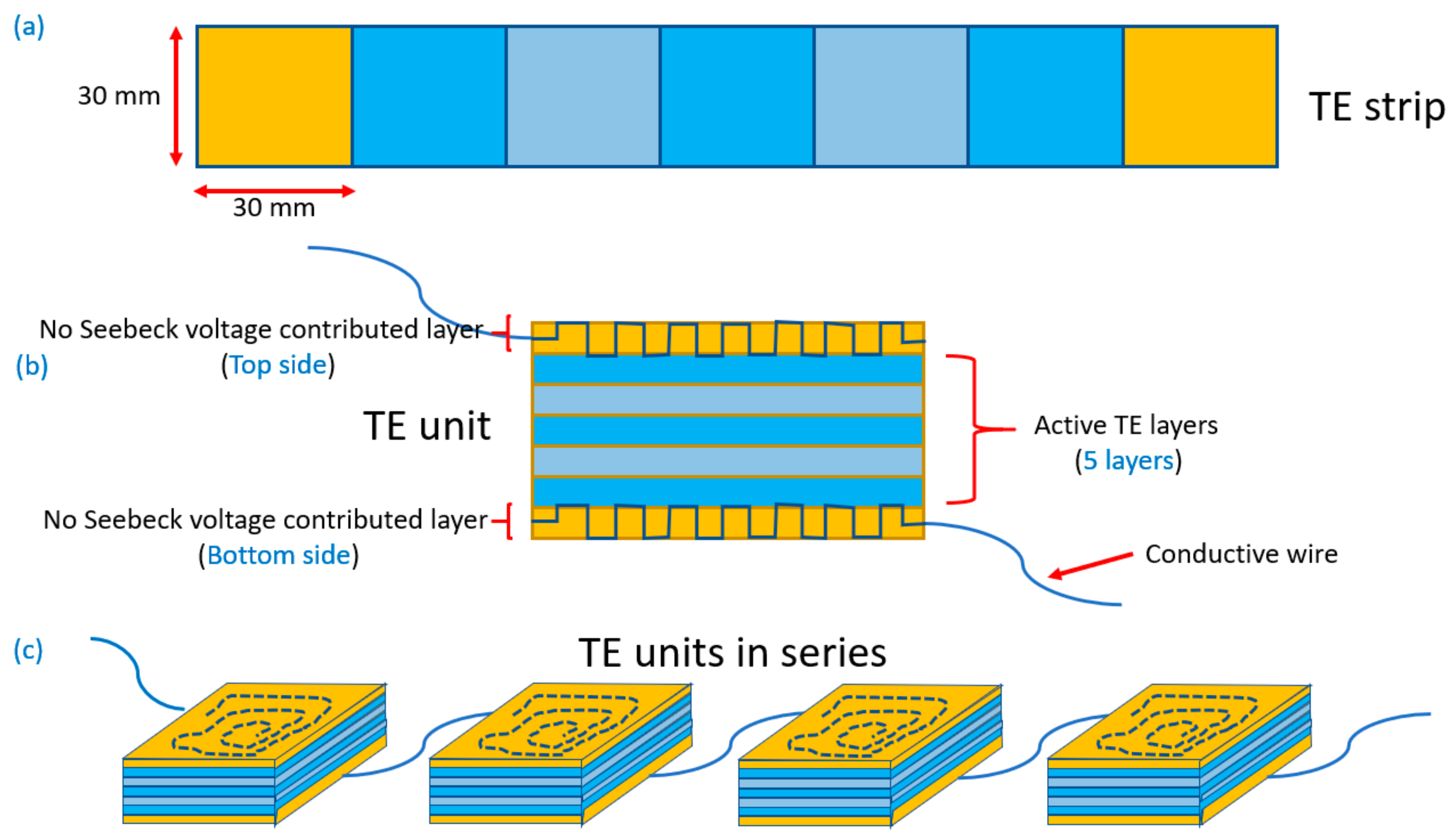
Figure 1. (a) A thermoelectric (TE) strip; (b) a typical TE unit; and (c) TE units in series.
Coatings 09 00831 g001
Figure 2. (a) A typical TE unit; (b) arrangement of the 48 sets of TE units in the chest area of the T-shirt.
Coatings 09 00831 g002
Figure 3. (a) TE T-shirt on a human body; (b) thermal image for a human body with a TE T-shirt.
Coatings 09 00831 g003
Figure 4. SEM image of the surface morphology of the TE fabric.
Coatings 09 00831 g004
Figure 5. The strip sample for resistance measurements.
Coatings 09 00831 g005
Figure 6. (a) The measuring architecture for the Seebeck coefficient extraction; (b) the Seebeck voltage and the Seebeck coefficient with temperature difference for a single TE unit.
Coatings 09 00831 g006
Figure 7. The four temperature measurement points.
Coatings 09 00831 g007
Figure 8. The transient TE properties for the T-shirt: (a) Seebeck coefficient and (b) output power.
Coatings 09 00831 g008