Article

Electrochemical Behavior, Microstructure, and Surface Chemistry of Thermal-Sprayed Stainless-Steel Coatings

by
Alexandre R. C. Nascimento
1,2,*,
Samantha Michelle Gateman
3,
Janine Mauzeroll
3,
Sylvio Savoie
2,
Robert Schulz
2 and
Christian Moreau
1,*
1
Department of Mechanical Industrial and Aerospace Engineering, Concordia University, Montreal, QC H3G 2W1, Canada
2
Institut de Recherche d’Hydro Québec, Varennes, QC J3X 1S1, Canada
3
Department of Chemistry, Laboratory for Electrochemical Reactive Imaging and Detection of Biological Systems, McGill University, Montreal, QC H3A 0B8, Canada
*
Authors to whom correspondence should be addressed.
Coatings 2019, 9(12), 835; https://doi.org/10.3390/coatings9120835
Submission received: 2 November 2019 / Revised: 29 November 2019 / Accepted: 4 December 2019 / Published: 7 December 2019
(This article belongs to the Section Corrosion, Wear and Erosion)

Abstract

:
Thermally sprayed stainless-steel coatings were produced with a wide range of deposition parameters. The electrochemical behavior of polished coatings was monitored for 3 weeks in 3.5 wt.% NaCl aqueous solution and compared to that of reference materials including a wrought stainless steel plate and a bulk ingot produced by arc melting of the spraying powder feedstock. Transitions in the polarization behavior are discussed based on the observed changes in coating microstructures as well as on the shifts in X-ray photoelectron spectra (XPS). Results show that the deposition parameters have a strong effect on the coating microstructures but the small differences in the polarization behavior of coatings mostly disappear after 1 week of testing. Microstructure evidence shows preferential corrosion at splats experiencing melting prior to deposition. Pitting and corrosion products between splat boundaries are also reported. XPS analysis shows that the coating surfaces are enriched in chromium oxides and hydroxides. Comparison between the coating and bulk stainless steels suggests that coating inherent defects play a major role on their impaired corrosion resistance.

1. Introduction

In thermal spraying, the successive impingements of hot gas-accelerated molten and semi-molten particles onto a substrate lead to the formation of a coating. The development of this industry-scale technique has allowed the replacement of erosion-corrosion resistant hard-chrome coatings in different applications including valves, hydraulic pistons, and aircraft landing gears [1,2]. When compared with other standard coating deposition methods such as weld-overlay, thermal spray has a reduced effect on the substrate’s chemistry and geometry, making it an interesting process for the repair of parts used, for example, in the paper and steel industries [3] as well as in hydroelectric turbines [4].
However, it is well-known that when compared to wrought or “bulk” parts of similar composition, sprayed coatings display an inferior corrosion performance. The causes were initially attributed to in-flight high-temperature oxidation, which is presumed to affect the particle’s composition, as well as to coating porosity, which could lead to localized corrosion [5,6]. Kawakita et al. studied the corrosion behavior in 3.4 wt.% NaCl aqueous solution of high-velocity oxygen fuel (HVOF) sprayed 316L stainless steel [7] and Hastelloy C coatings [8,9]. Based on current density measurements and the observation of corrosion products inside pores, the authors noticed that the coatings with minimum oxygen absorption and lowest porosity outperformed the others. This motivated the development of new spray processes that kept the supersonic gas velocities of HVOF spraying while pursuing lower flame temperatures. Examples of such processes include the warm-spray or “shrouded HVOF” [10,11] as well as the HVAF (high-velocity air fuel), which has received considerable attention in the scientific community. Instead of pure oxygen, HVAF uses highly pressurized air, substantially decreasing the flame temperature. Zeng et al. [12] compared 316L coatings produced by HVAF and HVOF in a salt-spray chamber, concluding that the lower amount of rust formation on HVAF coatings was due to their lower level of in-flight oxidation. Such results motivate further research and development on the use of thermal spray techniques to protect or repair surfaces from corrosion effects.
The development of thermal-sprayed coatings for any application involves selecting parameters that yield good deposition efficiency and performance. For example, with a factorial design approach, D. Zois et al. [13] were able to correlate fuel and oxygen flow rates with NiCr coatings’ corrosion potentials and residual stresses. Another approach consists in capturing and processing the particles’ thermal radiation signals and determining their velocities and temperatures during their flight towards the substrate. This allows one to create a process map [14], from which one may identify which deposition conditions are likely to yield the best coating properties.
In comparison to austenitic steels, ferritic alloys such as the UNS S44400 (henceforth designated SS444) are seldom considered as feedstock for producing corrosion-resistant coatings. When compared to austenitic steels, SS444 combines higher resistance to stress-corrosion cracking and lower nickel concentrations, reducing costs and making it a suitable material for applications including food processing [15], drinking water transport [16], and protection against hydrogen, chlorides, sulfides, and nitrides in oil distillation towers [17]. A recent report [18] on the corrosion behavior of SS444 coatings produced by HVOF revealed their inability to develop a protective passive layer. The effect was attributed to the powder atomization process that led to important modifications of the steel’s original chemical composition. Another important finding was that of a shift in the corrosion potential values (measured in a 3.5 wt.% NaCl solution) as a function of immersion time. The effect was associated with a preferential dissolution of iron, leaving non-protective Cr-rich oxide shells at the interface with the test solution.
The aim of the present work is to further explore the potentials and limitations of ferritic SS444 thermal-sprayed coatings. The results reported in [18] are extended, now including a thorough in-flight particle analysis as well as stainless steel coatings produced by HVAF. The coatings’ electrochemical behavior is monitored for longer immersion times and is compared to a bulk disc produced by arc melting the spray feedstock. Transitions in the electrochemical behavior are correlated with changes in the XPS spectra as well as extensive microstructure analysis at both surface and cross-section levels.

2. Materials and Methods

2.1. Feedstock and Spray Parameters

Water-atomized (Eutectic Castolin, Granby, Quebec, Canada) SS444 powder ( ρ   = 7.8 g∙cm−3) with nominal composition given in Table 1 was received in a broad particle size distribution. The feedstock was ball milled for 6 h and sieved through openings of 20 and 53 µm, resulting in D 50 = 40   ± 23   μ m as measured by laser diffraction with a HORIBA LA-900. The ball-milled powder was used to spray all coatings except for HVAF #1, in which the powder was used in the atomized state, having a D 50 = 48   ± 16   μ m after sieving through the same openings. The different size distributions were not produced on purpose. It was a result of passing powders with different morphologies (atomized and milled) through the sieves. Ball milled powders tend to have an elongated shape.
The water atomized feedstock was arc melted in the form of a disk. The process consisted of compacting 8 g of the feedstock powder with a pressure of 5 MPa. The compact pellet is then put inside a vacuum (10−6 mbar) furnace at 1000 °C for 1h to develop some strength. Subsequently, the pellet is placed inside an arc furnace chamber containing a tungsten electrode, a titanium getter, and a water cooled plate. The arc melting process was carried out under a vacuum of 10−3 mbar.
Based on the results in [7], four HVOF spray parameters were selected to produce coatings. The spray torch used was Praxair’s kerosene-fueled JP-8000 HP/HVOF® system. The HVAF coatings were produced at Pyro Spray company (Granby, QC, Canada) with the Uniquecoat M3TM system with two different spray parameters summarized in Table 2.
The tools used for in-flight particle temperature and velocity characterization were the DPV-evolution for HVOF and accuraspray-g3c (henceforth designated as accuraspray) for HVAF. Both tools are commercialized by Tecnar Inc (Saint-Bruno, QC, Canada). The temperatures are determined by two-color pyrometry with a 3% accuracy. Each system determines particle velocities differently. DPV-evolution uses a two-slit mask with a known distance between them. Accuraspray uses cross-correlation of the particles’ signals obtained at two different points spaced by a known distance (2% accuracy). The readers are referred to [19,20,21] for further details on the applications and limitations of these devices. Particle temperatures and velocities were determined at the same stand-off distances at which the substrates were positioned in front of the spray torches.
Bulk SS444 plates with dimensions of 190 mm × 120 mm were sandblasted to a roughness of 2.1 µm (measured with a Mitutoyo profilometer SJ-210) and then used as substrates for coating deposition. The substrate temperature was measured immediately after deposition by pointing an optical pyrometer at the center of the substrate on the coating side.

2.2. Microstructure and Chemical Analysis

The feedstock and coating structures were analyzed by optical (Olympus LEXT OLS4100, Tokyo, Japan) and scanning electron microscopy (SEM Hitachi S-3400N, Tokyo, Japan). The fraction of coatings microstructural features was determined by Image analysis using the software Image J 1.52A (National Institute of Health, Bethesda, Maryland, USA).
The methodology used to determine the coating’s chemical composition (semi-quantitative) by X-ray energy dispersive spectroscopy (EDX) consisted in doing point-analysis at the coating’s microconstituents, i.e., unmolten particles, re-solidified splats, and oxides, as well as by measuring a general composition over an area of 260 × 180 µm2. Each point analysis was carried out three times while the general analysis only once.

2.3. Electrochemical Characterization

To avoid the influence of different surface roughness, all coatings were initially ground in SiC (grit #320) paper then polished to mirror finish with diamond (3 µm) and alumina (0.05 µm) suspensions. Tests were carried out in stagnant 3.5 wt.% NaCl solution with a three-electrode cell having an Ag/AgCl reference electrode and an RuO2-coated titanium (dimensionally stable anode) as a counter electrode. The disc samples (diameter of 16 mm) were rinsed in distilled water and immersed for one hour in the test solution for stabilization of the open circuit potential (OCP). Potentiodynamic polarization tests were then performed starting at −0.75 V vs. Ag/AgCl until OCP + 150 mV at a scan rate of 0.167 mV/s. The choice of the potential range was empirical and aimed to characterize the sample polarization behavior without significantly changing its properties. After the polarization test, the samples are immersed in a stagnant solution of the same composition for a week to allow the coatings to corrode naturally. The non-adherent corrosion products are then removed by repeating the final 0.05 µm alumina polishing and the test routine is repeated three times, as illustrated in Figure 1. The reference samples did not undergo the entire cycle of tests. That was the case for as-polished coatings used in XPS analysis and for the bulk stainless steel samples. Determination of electrochemical parameters such as the corrosion potential ( E c o r r ), corrosion current ( i c o r r ) was done by the Levenberg–Marquardt method using CView® software (Schreibner associates Inc NC USA 28387). Each polarization was done once at each immersion time.

2.4. XPS Analysis

Prior to the XPS analysis, the wrought SS444 and arc melted feedstock underwent SiC paper grinding as well as diamond and alumina suspension polishing, like the HVOF/HVAF coatings. All samples were then dried in warm air and placed in a vacuum chamber. A standard aluminum X-ray source (Al kα = 1486.6 eV) was used to record XPS survey spectra (1–1486 eV). Argon-plasma etching was done over an area of 2 mm × 4 mm prior to each analysis. The probed area was a circle with 400 µm diameter, located at the center of the Ar-etched zone. Typical XPS probing depths are in the orders of a few tens of nanometers. High-resolution spectra have been done on C 1s, O 1s, Fe 2p, and Cr 2p. For each sample, three different analyses were performed to verify the homogeneity of the layer composition.

3. Results

3.1. In-Flight Particle Diagnostics & Spray Parameter Selection

The process map resulting from the choice of spray parameters is illustrated in Figure 2. It may be noticed that the HVOF-sprayed particles’ temperatures and velocities spread over a considerably wide range of values. On the other hand, the error bars (one standard deviation long) do not overlap. This shows that for each of the chosen HVOF deposition parameters, the particles absorb substantially different thermal and kinetic energies. This result was deliberately sought after in order to maximize the variability of HVOF coating microstructures and performances.
When compared to HVOF, the HVAF-sprayed particles experience significantly lower in-flight temperatures due to the flame cooling effect caused by the process’s relatively high air-flow rates. On average, their temperature is lower than the theoretical liquidus temperature of a bulk SS444 (1520 °C), which should substantially affect the high-temperature oxidation effects. It should be mentioned that the diagnostic tool used to characterize the HVAF-sprayed particles was the accuraspray system which determines temperatures and velocities as an ensemble (which is why the error bars are not reported) in a space volume of approximately 176 mm3. As for the HVOF-sprayed particles, the system used was the DPV-evolution, which can determine individual in-flight particle characteristics in a measurement volume inferior to 1 mm3.
The results in Figure 2 show that the in-flight particle temperature and the substrate temperature after spraying are not strongly correlated. The effect seems to be more strongly linked to the combustion O/F ratio used for spraying. For example, coatings HVOF #1 and HVOF #8 were produced with fuel-rich flames, burning kerosene at higher rates when compared to HVOF #3 and HVOF #5.

3.2. Microstructure and EDX Analysis

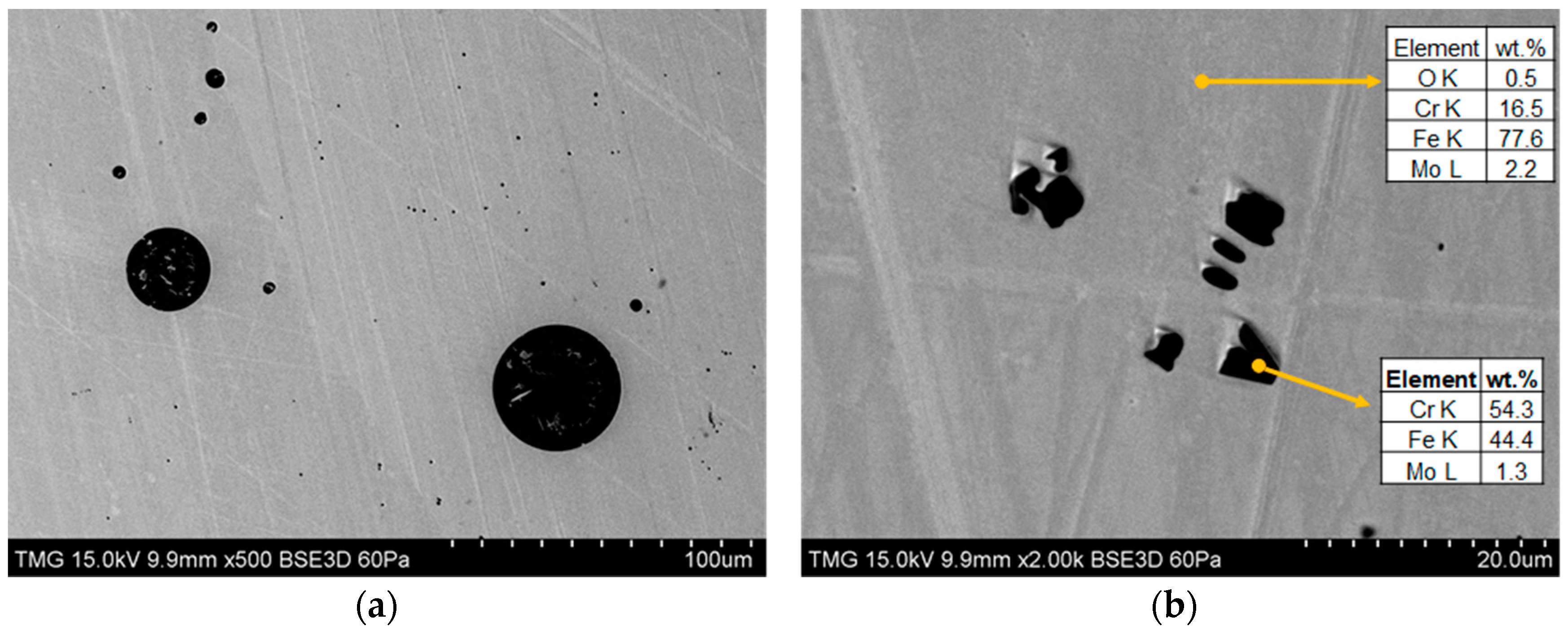
The powder feedstock displayed small dark precipitates which may also be found in the coating’s microstructures, as highlighted in Figure 3 by dashed circles. Details on the chemical composition of the precipitates are discussed in the subsequent section.
A closer look at Figure 3b reveals that the HVOF-sprayed SS444 coatings have three main microconstituents: unmolten splats that partially retain the feedstock morphology; a re-solidified zone comprising lamellar metallic and oxide splats that formed due to exposure to the high-temperature flames and; pores. These constituents are present in all the sprayed coatings. Table 3 summarizes the fraction of each constituent as measured by image analysis carried out on the coating cross-sections illustrated in Figure 4. The coatings produced at a higher O/F ratio (HVOF #3 and #5) have a higher fraction of unmolten particles. Conversely, the coatings produced with a lower O/F Ratio (HVOF #1 and #8) are mostly composed of re-solidified splats. As will be discussed later, this effect is attributed to different particle trajectories.
The porosity in coating HVOF #5 was significantly higher than the others, which probably derives from an undesirable combination of high in-flight particle temperatures and low velocities. The effect could also have been caused by splat pull-out during sectioning and/or polishing procedures. Another important remark concerns the coating HVOF #8 which, despite being formed by particles that experienced lowest in-flight temperature, also exhibited oxide clusters characterized by a darker grey color.
It is evident from Figure 4 that the coating HVAF #1 was formed mainly by unmolten splats. This may be explained by the larger particle sizes used and the particularly low in-flight particle temperatures used for its production. On the other hand, the HVAF #4 coating shared the same aspects of the HVOF coatings. This may be explained by the fact that the feedstock used to produce coating HVAF #4 was the same used to produce HVOF coatings and that the particle velocities prior to impact were relatively slow as compared with those that generated coating HVAF #1.
Based on thickness measurements, higher deposition efficiencies (DE) are achieved when HVOF-spraying with lower O/F ratios. According to [22], increasing the in-flight particle temperature also increases their ductility, which increases the process deposition efficiency until the material’s melting point is reached, leading to the process’s highest attainable DE. Coatings HVOF #1 and #8 contain a higher fraction of particles that experienced complete melting prior to deposition, hence their higher DE. The same rationale may explain why the DE of HVOF coatings was higher than that of HVAF. However, due to the use of a different, self-regulated powder feeding system, the flow rate for depositing coating HVAF #4 was significantly lower than the rest, which explains why this coating had the lowest thickness.
The EDX analysis main results are summarized in Table 4. The higher oxygen content in the resolidified zones, when compared to the unmolten splats, is probably linked to the influence of oxides more present in those regions (Figure 3b). The general composition results point-out to a higher oxygen uptake in coating HVOF #8, which can be linked to the presence of the large oxide clusters (Figure 4). Additionally, the HVAF coatings have an overall lower oxygen content, especially in the case of HVAF #1.
It is useful to compare the coating’s chemical composition with that of the wrought SS444, which under the same analysis conditions, exhibits an oxygen content of 0.5 wt.%. In terms of chromium content, the main element responsible for the protective passivation of stainless steels, most coatings display weight percentage values slightly inferior to that of the expected nominal range of 18–20% according to the general EDX analysis. In contrast, the local chromium content of the unmolten splats falls within the required nominal range. This apparent reduction of Cr wt.% may be a result of the interaction volume between the electron beam and the coating, comprising pores and oxides that have less Cr in their composition. On the other hand, the results also mean that Cr distribution on the coating surfaces is very heterogeneous. For example, the EDX analysis performed on precipitates present in both the feedstock and coatings revealed an enrichment in chromium and silicon, which was also reported in [18]. These factors may play an important role in the coating’s electrochemical behavior.
The arc melting process led to significant densification of the sintered pack of particles. However, pores and different types precipitates were observed (Figure 5). Due to their spherical geometry, it is believed that the pores were originated from gases entrapped in the melting pool. The EDX analysis performed on the precipitates revealed a Cr weight fraction of 54%. As compared with melt atomization, the cooling rates after arc melting are relatively slow. Therefore, one may argue that such precipitates are formed by coalescence of the small precipitates found in the feedstock.
The oxygen content of the arc melted steel was of 0.5 wt.%, considerably lower than what was measured for the coatings. Two factors may explain such findings. Firstly, the arc melted feedstock did not undergo the oxidation associated with the thermal spray process. Secondly, a slag formed and floated on top of the melt pool during the process. It is believed that the slag may have absorbed part of the oxygen entrapped in the powder during atomization. Upon solidification and polishing, the slag was completely removed from the feedstock.

3.3. Potentiodynamic Polarization

For the sake of clarity, only a limited number of polarization curves are shown in Figure 6. When comparing the polarization curves of the (HVOF #1—1 h) coating to that of the wrought SS444, one will notice a significantly lower corrosion potential as well as a two-order of magnitude higher corrosion current. The measured E c o r r and i c o r r values for the SS444 coatings after 1 hour of immersion are in good agreement with other stainless steel coatings produced by HVOF [5,6], as well as with a vacuum-sintered 434L powder metallurgy (PM) stainless steel [23]. When comparing the polarization behaviors of the arc melted feedstock and the wrought stainless steel, one may notice a much closer behavior when compared to that of the coatings. Nevertheless, the breakdown at E = 0.17   V implies some impairment of the corrosion resistance of the arc melted disc, which may be caused by the pores and Cr-rich precipitates shown in Figure 5.
At potentials significantly far from the corrosion potential | E E c o r r | > 50   mV , the sprayed coatings behavior distinguishes from that of the wrought materials by the absence of a passivation plateau. With increasing immersion time, changes are observed in the shapes of both anodic and cathodic branches of the curves, suggesting a modification in the kinetics of the corrosion reactions.
When compared to HVOF, the use of HVAF spraying does not lead to significant changes in the electrochemical response of the stainless steel coatings. Their corrosion potential was approximately 100 mV higher than that of HVOF coatings throughout the tests.
The polarization behavior of the sprayed SS444 coatings was similar in almost all instances and is summarized in Figure 7. The corrosion potentials drop about 100 mV during the first week of immersion, after which the E c o r r values display a slight tendency to increase with immersion time. A similar trend was observed for the corrosion potential of SUS316L coatings in Seawater [7]. The average corrosion current i c o r r of the coatings did not vary as strongly, ranging between 20–60 µA·cm−2 throughout the 3-week testing.

3.4. Changes in Electrode Surface and Cross Section

The effects of corrosion on the HVOF coating surfaces are illustrated in Figure 8. As compared with the pristine polished coatings, the corroded electrodes display an increase in porosity and in the quantity of corrosion products which seem to form preferentially in the re-solidified zone, while the unmolten particles remain apparently unaffected. As suggested in [24,25,26], these results endorse the hypothesis of the formation of galvanic microcells between coating constituents. As revealed by EDX analysis (Table 4), the heterogenous chromium distribution throughout the coating may be the driving force for the corrosion reactions. As the electrolyte penetrates through the coating thickness, more such heterogeneities are exposed to the solution, leading to a preferential corrosion path through boundaries between splats.
It has been proposed in [26] that the coating corrosion resistance may be improved by reducing or eliminating the chemical heterogeneities between microconstituents. While coating HVAF #1 is mostly comprised of unmolten splats, its electrochemical behavior was not markedly different from that of the other materials. On the other hand, the microstructural features observed after the corrosion tests deserve mention. As illustrated in Figure 9, several pits were formed on the coating splats. The formation of pits implies the breakdown of a passive film or the formation of a micro/nano galvanic couple. Evidence of such films was shown in Figure 6, where the anodic current of coating HVAF#1 nearly stabilizes at 35 µA.cm−2. Similar behavior was reported for SS444 HVOF coatings in [18]. At the HVAF #1 coating cross-section, the formation of corrosion products rich in Cl highlights the ability of the electrolyte to penetrate through the voids between splats. The same was observed at the HVOF coatings though to a much lesser extent. The effect may be attributed to the relatively large gaps at the HVAF #1 splat boundaries (Figure 9a).

3.5. XPS Analysis

The survey XPS analysis summarized in Table 5 reveals that the Bulk SS444, arc melted feedstock and the HVAF #1 coating have similar oxygen concentrations, substantially lower than what was measured for the remaining coatings. When comparing polished coatings (not exposed to the tests) to those exposed to the test solution for 3-weeks, one notices an increase in the Cr/Fe ratio. This phenomenon may be attributed to a preferential dissolution of Fe at the electrode surface which was also observed in [18] and on early studies regarding the passivity of Fe-Cr alloys [27]. If one considers the standard electrode potentials of Cr(III) and Fe(II), respectively −0.74 V and −0.41 V versus a standard hydrogen electrode, one could say that the shift observed in the E c o r r of the coatings during the first week of immersion is caused by the surface Cr-enrichment.
The deconvolution of a sample’s high-resolution XPS spectra allows one to estimate the contribution of each element’s oxidation state to the overall signal. Following the rationale used in [28], observation of Figure 10 and Table 6 implies that chromium surface atoms manifest in three main oxidation states, corresponding to metallic Cr(0), Cr(III)-(Cr2O3), and Cr(II)-Cr(OH)3. One may easily notice that the contributions of the Cr oxidation states are very similar in the Bulk SS444, arc melted feedstock and in the HVAF #1 coating. However, during the 3-week tests, the surface of coating HVAF #1 is enriched in Cr-oxides and depleted in hydroxides, resembling the other sprayed coatings, which have a marked presence of Cr2O3 from the as-polished condition.
Deconvolution of the iron XPS peaks indicate that, when compared to a bulk SS444 plate, more Fe atoms achieve a higher oxidation state Fe(III) on the surface of the sprayed coatings and on the arc melted feedstock. This implies that the film formed on the surface of the latter materials has a limited ability in preventing Fe from oxidation in the test solution.
Concerning the oxidation state of oxygen, metallic oxides (O2−) and hydroxides (OH) have a relatively stronger influence on the XPS spectra of the HVOF coatings, which may be attributed to the effects of high-temperature oxidation during spray as well as to the corrosion process itself, since the relative contribution of O2− and OH to the XPS spectra is further increased at the corroded electrodes. Hydrocarbon contamination (C=O) possibly deriving from sample manipulation did not have a marked influence in the overall oxygen signal obtained from the investigated materials.

4. Discussion

One of the factors that may explain the substantial drop observed in the corrosion resistance of sprayed coatings is not related to thermal spraying itself, but on the quality of the feedstock production. One of the main characteristics of the bulk SS444 is the presence of evenly distributed Ti- and Nb-rich precipitates that form upon solidification [29]. These elements added in small quantities are strong carbide formers and prevent the onset of chromium carbide precipitation and hence, intergranular corrosion [29,30,31]. Such Ti- or Nb-rich precipitates were not observed in the coatings nor in the arc melted feedstock which may be explained by a combination of two factors: (i) the relatively high cooling rates in the atomization process (103–106 °C/s [32]) and (ii) the low wt.% addition of both elements in the steel formulation. The rapid solidification of the metal implies very little time for Ti and Nb atoms to combine with the carbon and form the precipitates. Instead, these atoms may have remained in a metastable solid solution with the remaining elements. In these conditions and, with a wt.% < 0.2%, the EDX analysis would be incapable of detecting Ti and Nb.
Another possibility is that Ti and Nb atoms were totally or partially lost during powder atomization, as hypothesized previously [18]. Ti is well-known for being prone to oxidation and, according to the powder manufacturer, raw material melting is done without atmospheric control. Moreover, Ti and Nb carbides and nitrides have melting points in excess of 3000 °C and may not have been properly dissolved back into the molten steel prior to atomization. The presence of Cr-rich precipitates in the arc melted feedstock (Figure 5) supports this hypothesis since, according to the isothermal precipitation diagrams of ferritic stainless steels [31] Ti, Nb carbonitrides tend to form before Cr-carbides.
Despite the clear metallurgical flaws, the polarization response of the arc melted feedstock was much closer to that of the bulk SS444 when compared to the sprayed coatings. Considering these observations, the high-temperature oxidation occurring during atomization and during spray cannot explain the significant drop in the corrosion behavior of the sprayed coatings. More likely, is that the coating’s high density of defects (including pores, splat boundaries, and oxides) and heterogeneous distribution of alloying elements prevent the development of an effective protective film. Stainless steels produced by powder metallurgy [23,33,34] share similar structural defects and also an inferior corrosion resistance when compared to that of wrought parts. By melting the feedstock, the density of defects is drastically reduced, allowing the entire surface to respond more homogeneously when exposed to the electrolyte.
The correlation between particle in-flight properties and the coating structures presented some unexpected results. For example, coating HVOF #8 showed the highest level of oxidation (as measured by EDX) even though the particles experienced a relatively short period of exposure to the flame. As previously mentioned, it was during the production of HVOF #8 that the highest consumption of kerosene as well as the highest post-spraying substrate temperature was measured. It is believed that the oxidation of HVOF #8 particles did not occur during their flight, but while exposed to the HVOF torch flame following their deposition on the substrate. The use of a substrate cooling method might have prevented such an effect. Another apparent incoherence arises from the higher fraction of unmolten splats in coatings HVOF #5 and HVOF #3 which, according to the DPV-evolution diagnostics experienced the highest in-flight temperatures. The JP-8000 HVOF torch is characterized by a radial powder feeding system [35]. One may argue that the change in the O/F ratio interferes with the regions of high and low pressures in the torch’s nozzle, which ultimately affected the trajectory of the particles along the gas stream. As the measurement volume of the DPV-evolution system is less than 1 mm3, it is possible that the temperature measurements did not account for the contributions from relatively cold and large particles. Different feedstock carrier gas flow rates might be necessary to improve particle trajectory and melting along the flame stream.
Even though a large range of coating microstructures were obtained, their electrochemical responses were very similar. As seen in [18], preferential dissolution of iron leads to a surface chromium enrichment that, based on the behavior of the corrosion potential measurements, stabilizes after the first week of immersion in the test solution. This Cr-rich layer seems to provide some level of protection, especially for coating HVAF #1, which showed evidence of a passivation process and the formation of pits. The use of spray techniques that reduce in-flight particle oxidation are, therefore, desirable and should be encouraged. On the other hand, while XPS and polarization curves give a good insight into the changes on the surface of coatings, they give little information on the reactions happening inside coating pores and boundaries between splats. The lack of fusion of HVAF #1 particles allowed the electrolyte to penetrate the coating more easily than others, facilitating localized reactions. In summary, if one strives to create very dense coatings by melting particles during spray, high levels of in-flight oxidation are likely to occur, leading to preferential corrosion on certain coating constituents. In contrast, if one focuses on avoiding excessive in-flight temperatures, the boundaries between splats may be too large, facilitating electrolyte penetration. Based on the state-of-the-art spray technologies and on the results of the present work, it may be said that narrowing the corrosion performance gap between the coating and bulk materials cannot be achieved solely by controlling the spray parameters.
That does not mean that SS444 thermal-sprayed coatings do not have industrial value. For example, they may be used as physical barriers, keeping underlying substrates within acceptable dimensional tolerances until further maintenance is required. Moreover, being more active than the substrate, such coatings may provide cathodic protection in the same fashion as zinc protects galvanized steels. Finally, if post-processing techniques such as sealing [12,36,37] and surface re-melting [26] are employed, one may expect substantial improvements on their corrosion performance, albeit the increase in cost associated with these post modification steps.

5. Conclusions

In the present work, the electrochemical behavior of ferritic stainless steel (SS444) coatings produced by state-of-the-art HVOF and HVAF were continuously monitored for 3 weeks. Their behavior changes were correlated with variations in the electrode surface chemistry and microstructural features. The main conclusions that may be drawn from the study are summarized as follows.
Unlike bulk stainless steels, upon exposure to a 3.5 wt.% NaCl aqueous solution, the sprayed SS444 coatings did not undergo spontaneous passivation and protection, but experienced preferential corrosion of Fe while the surfaces becomes enriched in chromium oxides and hydroxides, which markedly affects their electrochemical behavior, especially during the first week of immersion. However, these changes do not produce an important effect on the coatings’ corrosion rates.
The use of modern HVAF spraying techniques may render stainless steel coatings substantially lower levels of oxidation as compared to HVOF. The effect, however, is insufficient to give SS444 HVAF coatings the ability to create protective passive films.
The inferior corrosion resistance of the coatings, when compared to bulk materials, arise primarily from the high density of defects inherent to the spray process including pores, boundaries between splats and a heterogeneous chromium distribution among coating constituents, attributed to the presence of Cr-rich precipitates in the feedstock powder. It is unlikely that such defects can be removed solely by controlling deposition parameters.

Author Contributions

Data curation, A.R.C.N.; formal analysis, A.R.C.N.; funding acquisition, J.M., R.S., and C.M.; investigation, A.R.C.N.; methodology, A.R.C.N., S.S., R.S., and C.M.; project administration, J.M. and C.M.; resources, R.S., S.S., and C.M.; supervision, R.S. and C.M.; writing—original draft, A.R.C.N.; writing—review and editing, A.R.C.N., S.M.G., R.S., and C.M.

Funding

This research was funded by NSERC grant STPGP 478885-15 and by Hydro-Québec.

Acknowledgments

The authors would like to express their gratitude to Éric Ménard from PyroSpray® (Granby – QC, Canada) and Fariba Tarasi for their contribution to the production of HVAF coatings.

Conflicts of Interest

The authors declare no conflict of interest.

References

  1. Vackel, A.; Dwivedi, G.; Sampath, S. Structurally Integrated, Damage-Tolerant, Thermal Spray Coatings. Jom 2015, 67, 1540–1553. [Google Scholar] [CrossRef] [Green Version]
  2. Espallargas, N.; Berget, J.; Guilemany, J.M.; Benedetti, A.V.; Suegama, P.H. Cr3C2–NiCr and WC–Ni thermal spray coatings as alternatives to hard chromium for erosion–corrosion resistance. Surf. Coatings Technol. 2008, 202, 1405–1417. [Google Scholar] [CrossRef]
  3. Tan, J.C.; Looney, L.; Hashmi, M.S.J. Component repair using HVOF thermal spraying. J. Mater. Process. Technol. 1999, 92–93, 203–208. [Google Scholar] [CrossRef]
  4. Lavigne, S.; Pougoum, F.; Savoie, S.; Martinu, L.; Klemberg-Sapieha, J.E.; Schulz, R. Cavitation erosion behavior of HVOF CaviTec coatings. Wear 2017, 386–387, 90–98. [Google Scholar] [CrossRef]
  5. Suegama, P.H.; Fugivara, C.S.; Benedetti, A.V.; Fernández, J.; Delgado, J.; Guilemany, J.M. Electrochemical behavior of thermally sprayed stainless steel coatings in 3.4% NaCl solution. Corros. Sci. 2005, 47, 605–620. [Google Scholar] [CrossRef]
  6. Guilemany, J.M.; Fernández, J.; Espallargas, N.; Suegama, P.H.; Benedetti, A.V. Influence of spraying parameters on the electrochemical behaviour of HVOF thermally sprayed stainless steel coatings in 3.4% NaCl. Surf. Coatings Technol. 2006, 200, 3064–3072. [Google Scholar] [CrossRef]
  7. Kawakita, J.; Fukushima, T.; Kuroda, S.; Kodama, T. Corrosion behaviour of HVOF sprayed SUS316L stainless steel in seawater. Corros. Sci. 2002, 44, 2561–2581. [Google Scholar] [CrossRef]
  8. Kawakita, J.; Kuroda, S.; Fukushima, T.; Kodama, T. Corrosion resistance of HVOF sprayed HastelloyC nickel base alloy in seawater. Corros. Sci. 2003, 45, 2819–2835. [Google Scholar] [CrossRef]
  9. Kawakita, J.; Kuroda, S. Oscillational corrosion potential of HastelloyC coatings fabricated by GS-HVOF spraying. Corros. Sci. 2005, 47, 2053–2062. [Google Scholar] [CrossRef]
  10. Dolatabadi, A.; Mostaghimi, J.; Pershin, V. Effect of a cylindrical shroud on particle conditions in high velocity oxy-fuel spray process. Sci. Technol. Adv. Mater. 2002, 3, 245–255. [Google Scholar] [CrossRef]
  11. Kuroda, S.; Watanabe, M.; Kim, K.; Katanoda, H. Current Status and Future Prospects of Warm Spray Technology. J. Therm. Spray Technol. 2011, 20, 653–676. [Google Scholar] [CrossRef] [Green Version]
  12. Zeng, Z.; Sakoda, N.; Tajiri, T.; Kuroda, S. Structure and corrosion behavior of 316L stainless steel coatings formed by HVAF spraying with and without sealing. Surf. Coatings Technol. 2008, 203, 284–290. [Google Scholar] [CrossRef]
  13. Zois, D.; Wentz, T.; Dey, R.; Sampath, S.; Weyant, C.M. Simplified model for description of HVOF NiCr coating properties through experimental design and diagnostic measurements. J. Therm. Spray Technol. 2013, 22, 299–315. [Google Scholar] [CrossRef]
  14. Turunen, E.; Varis, T.; Hannula, S.P.; Vaidya, A.; Kulkarni, A.; Gutleber, J.; Sampath, S.; Herman, H. On the role of particle state and deposition procedure on mechanical, tribological and dielectric response of high velocity oxy-fuel sprayed alumina coatings. Mater. Sci. Eng. A 2006, 415, 1–11. [Google Scholar] [CrossRef]
  15. Washko, S.D.; Aggen, G. Wrought Stainless Steels. In Properties and Selection: Irons, Steels, and High-Performance Alloys; ASM International: Novelty, OH, USA, 1990; Volume 1, pp. 841–907. [Google Scholar]
  16. Bitondo, C.; Bossio, A.; Monetta, T.; Curioni, M.; Bellucci, F. The effect of annealing on the corrosion behaviour of 444 stainless steel for drinking water applications. Corros. Sci. 2014, 87, 6–10. [Google Scholar] [CrossRef]
  17. Silva, C.C.; Machado, J.P.S.E.; Sobral-Santiago, A.V.C.; de Sant’Ana, H.B.; Farias, J.P. High-temperature hydrogen sulfide corrosion on the heat-affected zone of the AISI 444 stainless steel caused by Venezuelan heavy petroleum. J. Pet. Sci. Eng. 2007, 59, 219–225. [Google Scholar] [CrossRef]
  18. Gateman, S.M.; Halimi, I.; Costa Nascimento, A.R.; Lacasse, R.; Schulz, R.; Moreau, C.; Chromik, R.; Mauzeroll, J. Using macro and micro electrochemical methods to understand the corrosion behavior of stainless steel thermal spray coatings. npj Mater. Degrad. 2019, 3, 25. [Google Scholar] [CrossRef] [Green Version]
  19. Mauer, G.; Vaßen, R.; Stöver, D. Comparison and applications of DPV-2000 and accuraspray-g3 diagnostic systems. J. Therm. Spray Technol. 2007, 16, 414–424. [Google Scholar] [CrossRef]
  20. Zimmermann, S.; Vogli, E.; Kauffeldt, M.; Abdulgader, M.; Krebs, B.; Rüther, B.; Landes, K.; Schein, J.; Tillmann, W. Supervision and measuring of particle parameters during the wire-arc spraying process with the diagnostic systems accuraspray-g3 and LDA (laser-doppler-anemometry). J. Therm. Spray Technol. 2010, 19, 745–755. [Google Scholar] [CrossRef]
  21. Colmenares-Angulo, J.; Shinoda, K.; Wentz, T.; Zhang, W.; Tan, Y.; Sampath, S. On the response of different particle state sensors to deliberate process variations. J. Therm. Spray Technol. 2011, 20, 1035–1048. [Google Scholar] [CrossRef]
  22. Hanson, T.C.; Settles, G.S. Particle Temperature and Velocity Effects on the Porosity and Oxidation of an HVOF Corrosion-Control Coating. J. Therm. Spray Technol. 2003, 12, 403–415. [Google Scholar] [CrossRef]
  23. Velasco, F.; Bautista, A.; González-Centeno, A. High-temperature oxidation and aqueous corrosion performance of ferritic, vacuum-sintered stainless steels prealloyed with Si. Corros. Sci. 2009, 51, 21–27. [Google Scholar] [CrossRef]
  24. Bolelli, G.; Lusvarghi, L.; Giovanardi, R. A comparison between the corrosion resistances of some HVOF-sprayed metal alloy coatings. Surf. Coatings Technol. 2008, 202, 4793–4809. [Google Scholar] [CrossRef]
  25. Bolelli, G.; Lusvarghi, L.; Barletta, M. Heat treatment effects on the corrosion resistance of some HVOF-sprayed metal alloy coatings. Surf. Coatings Technol. 2008, 202, 4839–4847. [Google Scholar] [CrossRef]
  26. Ahmed, N.; Bakare, M.S.; McCartney, D.G.; Voisey, K.T. The effects of microstructural features on the performance gap in corrosion resistance between bulk and HVOF sprayed Inconel 625. Surf. Coatings Technol. 2010, 204, 2294–2301. [Google Scholar] [CrossRef] [Green Version]
  27. Kirchheim, R.; Heine, B.; Fischmeister, H.; Hofmann, S.; Knote, H.; Stolz, U. The passivity of iron-chromium alloys. Corros. Sci. 1989, 29, 899–917. [Google Scholar] [CrossRef]
  28. Marcelin, S.; Pébère, N.; Régnier, S. Electrochemical characterisation of a martensitic stainless steel in a neutral chloride solution. Electrochim. Acta 2013, 87, 32–40. [Google Scholar] [CrossRef] [Green Version]
  29. Gateman, S.M.; Stephens, L.I.; Perry, S.C.; Lacasse, R.; Schulz, R.; Mauzeroll, J. The role of titanium in the initiation of localized corrosion of stainless steel 444. npj Mater. Degrad. 2018, 2, 5. [Google Scholar] [CrossRef] [Green Version]
  30. Juuti, T.; Rovatti, L.; Mäkelä, A.; Karjalainen, L.P.; Porter, D. Influence of long heat treatments on the laves phase nucleation in a type 444 ferritic stainless steel. J. Alloys Compd. 2014, 616, 250–256. [Google Scholar] [CrossRef]
  31. Silva, C.C.; Farias, J.P.; Miranda, H.C.; Guimarães, R.F.; Menezes, J.W.A.; Neto, M.A.M. Microstructural characterization of the HAZ in AISI 444 ferritic stainless steel welds. Mater. Charact. 2008, 59, 528–533. [Google Scholar] [CrossRef]
  32. Pryds, N.H.; Pedersen, A.S. Rapid solidification of martensitic stainless steel atomized droplets. Metall. Mater. Trans. A Phys. Metall. Mater. Sci. 2002, 33, 3755–3761. [Google Scholar] [CrossRef]
  33. Pandya, S.; Ramasrishna, K.S.; Annamalai, A.R.; Upadhyaya, A. Effect of sintering temperature on mechanical and electrochemical properties of austenitic stainless steel. Mater. Sci. Eng. A 2012. [Google Scholar] [CrossRef]
  34. Bautista, A.; Gonzalez-Centeno, A.; Blanco, G.; Guzman, S. Application of EIS to the study of corrosion behaviour of sintered ferritic stainless steels before and after high-temperature exposure. Mater. Charact. 2008, 59, 32–39. [Google Scholar] [CrossRef]
  35. Kamnis, S.; Gu, S. 3-D modelling of kerosene-fuelled HVOF thermal spray gun. Chem. Eng. Sci. 2006, 61, 5427–5439. [Google Scholar] [CrossRef]
  36. Knuuttila, J.; Sorsa, P.; Mäntylä, T.; Knuuttila, J.; Sorsa, P. Sealing of thermal spray coatings by impregnation. J. Therm. Spray Technol. 1999, 8, 249–257. [Google Scholar] [CrossRef]
  37. Wang, Y.; Jiang, S.L.; Zheng, Y.G.; Ke, W.; Sun, W.H.; Wang, J.Q. Effect of porosity sealing treatments on the corrosion resistance of high-velocity oxy-fuel (HVOF)-sprayed Fe-based amorphous metallic coatings. Surf. Coatings Technol. 2011, 206, 1307–1318. [Google Scholar] [CrossRef]
Figure 1. The flowchart illustrates the preparation and characterization steps to which each sample was subjected.
Coatings 09 00835 g001
Figure 2. (a) Process map containing the in-flight particle velocities and temperatures used to produce the studied coatings. (b) The substrate temperatures measured right after deposition are also reported.
Coatings 09 00835 g002
Figure 3. (a) Small precipitates can be found in the powder feedstock as well as in the sprayed coatings. (b) Coating constituents include unmolten splats (circled in yellow), a re-solidified zone, and pores.
Coatings 09 00835 g003
Figure 4. As-sprayed SS444 coating microstructures contain similar microstructural features including unmolten splats, a re-solidified zone containing splats, and oxides, and finally, pores.
Coatings 09 00835 g004
Figure 5. (a) The arc melted feedstock showed a dense structure. However, a few pores and Cr-rich precipitates were observed. (b) The arrows indicate the local where EDX analysis was carried out.
Coatings 09 00835 g005
Figure 6. Polarization curves measured for a bulk SS444, the arc melted feedstock and coatings HVOF #1 and HVAF #1.
Coatings 09 00835 g006
Figure 7. Evolution of the stainless steel coating’s parameters (a) corrosion potential and (b) corrosion current. The dashed line corresponds to the averaged values of all coatings. Error bars correspond to one standard deviation.
Coatings 09 00835 g007
Figure 8. Change of HVOF coating microstructure features in (a) top surface of coating HVOF #3. (b) At HVOF #8 cross-section.
Coatings 09 00835 g008
Figure 9. Evolution of coating HVAF #1 microstructure with increasing testing time. (a) as-polished coating surface, (b) formation of micro-pits throughout the coating surface, (c) corroded HVAF #1 coating cross-section. (d) EDX analysis of corrosion products.
Coatings 09 00835 g009
Figure 10. High-resolution XPS spectra obtained on stainless steel surfaces. The grey lines indicate which peaks are used for spectra deconvolution. The red line is the resulting sum of the three deconvolution peaks.
Coatings 09 00835 g010
Table 1. Nominal composition of a bulk SS444. The * indicates the maximum element in wt.% the steel should bare.
CompositionCMnPSSiNCrNiMoTi + NbFe
wt.%0.025 *1.00 *0.04 *0.03 *1.00 *0.035 *17.5–19.51.00 *1.75–2.50.20 *Bal
Table 2. Summary of the spray parameters used for high-velocity oxygen fuel (HVOF) and high-velocity air-fuel (HVAF) spraying. * LPM: Liters per minute.
HVOF #FeedstockO2 Flow RateFuel Flow RateO/F RatioCombustion PressureOther Parameters
(LPM) *(LPM) *-(kPa)
1Ball milled470180.8372Feed Rate44 g/min
3870231.17689Stand-off Distance33 cm
5588151.18414Argon Flow Rate9.4 LPM
8729280.79655Number of Passes15
------Transversal Speed50 cm/s
HVAF #FeedstockAir PressureFuel PressureFeed RateOther Parameters
(kPa)(kPa)(g/min)
1Atomized78069070Stand-off distance30 cm
4Ball milled50Number of Passes20
-----Transversal Speed1 m/s
Table 3. Area fraction of coating microconstituents as determined by image analysis.
Coating ID% Unmolten% Re-Solidified% PoresThickness (µm)
HVOF #115.983.80.3612
HVOF #328.570.21.3564
HVOF #526.471.52.1462
HVOF #814.585.00.5574
HVAF #199.3-0.7472
HVAF #43168.70.3280
Table 4. X-ray energy dispersive spectroscopy (EDX) analysis performed over the coating’s microconstituents as well as over a 260 × 180 µm2 area.
Coating IDConstituentElement Weight %Cr/Fe
O KSi KCr KMn KFe KNi KMo K
HVOF #1Unmolten2.1 ± 0.50.5 ± 0.118.1 ± 0.30.6 ± 0.376 ± 1-2.2 ± 0.20.24
Re-solidified5 ± 20.5 ± 0.318 ± 20.8 ± 0.774 ± 4-2.2 ± 0.10.24
Oxide22 ± 130.3 ± 0.116 ± 30.4 ± 0.159 ± 12-1.5 ± 0.60.27
General8.70.416.70.471.70.02.10.23
HVOF #3Unmolten3 ± 10.6 ± 0.218.4 ± 0.30.5 ± 0.175 ± 30.6 *2.0 ± 0.10.24
Re-solidified3 ± 20.4 ±0.117 ± 20.6 ± 0.177 ± 1-2.3 ± 0.10.21
Oxide27 ± 50.4 ± 0.314 ± 20.4 ± 0.157 ± 3-1.4 ± 0.10.25
General8.50.416.40.671.7-2.10.23
HVOF #5Unmolten2.0 ± 0.30.4 ± 0.117.8 ± 0.60.4 ± 0.177.1 ± 0.20.7 *2.1 ± 0.10.23
Re-solidified6 ± 40.5 ± 0.220 ± 36 ± 572 ± 6-1.9 ± 0.40.27
Oxide30 ± 1-13.5 ± 0.30.4 *55.0 ± 0.3-1.3 ± 0.40.24
General8.10.416.60.571.8-2.20.23
HVOF #8Unmolten2.5 ± 0.70.5 ±0.118.1 ± 0.10.4 ±0.176 ±10.6 *2.2 ± 0.20.24
Re-solidified3 ± 20.2 ± 0.116.7 ± 0.30.4 *78 ± 3-2.3 ± 0.20.22
Oxide29.8 ± 0.30.4 ± 0.214 ± 30.4 ± 0.154 ± 3-1.3 ± 0.10.26
General10.70.316.40.569.8-2.00.23
HVAF #1Unmolten0.6 ± 0.10.2 ± 0.117.8 ± 0.2-79.6 ± 0.5-2.2 ± 0.10.22
General2.50.418.00.576.0-2.10.24
HVAF #4Unmolten2.2 ± 0.80.5 ± 0.218.4 ± 0.30.4 *76.7 ± 0.9-2.2 ± 0.20.24
Re-solidified2.8 ± 0.80.4 ± 0.118.0 ± 0.50.5 ± 0.176.3 ± 0.9-2.2 ± 0.30.24
Oxide25 ± 50.4 ± 0.116 ± 20.6 *57 ± 3-1.3 ± 0.10.28
General5.20.417.4-74.5 2.10.23
Precipitates5.7 ± 31.5 ± 120 ± 41 ± 170 ± 7-1.7 ± 0.40.29
Reported values with * were detected once or twice out of the three measurements.
Table 5. Survey X-ray photoelectron spectra (XPS) analysis of the investigated materials.
MaterialFe 2pO 1sCr 2pMo 3dBal.Cr/Fe
% atomic
Bulk Plate SS44446.022.916.52.412.10.36
Arc Melted SS44453.820.116.91.57.70.31
HVAF #1—As Polished42.723.112.81.320.20.30
HVAF #1—Corroded32.131.211.71.223.90.36
HVAF #4—Corroded32.241.017.50.88.50.54
HVOF #1—Corroded29.739.614.31.115.20.48
HVOF #3—As Polished33.140.715.00.510.70.46
HVOF #3—Corroded28.446.816.00.48.40.57
HVOF #5—Corroded36.037.313.81.311.60.38
HVOF # 8—Corroded30.743.116.90.88.50.55
Table 6. Percentual contribution of Cr, Fe, and O oxidation states to the high-resolution XPS spectra.
Oxidation StateBinding EnergyBulk SS444Arc MeltedHVAF #1HVOF #3
As-PolishedCorrodedAs-PolishedCorroded
(eV)Area %
O2-530.4 ± 0.0514.012.511.617.221.625.7
OH-531.5 ± 0.028.97.66.711.913.816.8
C=O533.0 ± 0.22.12.04.92.25.34.7
Cr(0)574.3 ± 0.1 5.35.24.42.82.41.9
Cr(II)576.3 ± 0.16.35.74.58.111.913.0
Cr(III)578.8 ± 0.45.05.74.10.80.91.3
Fe(0)706.7 ± 0.0118.419.914.59.09.36.0
Fe(II)707.5 ± 0.0319.817.213.29.08.628.6
Fe(III)709.2 ± 0.1 8.317.215.414.115.215.9

