Effect of Brazing Temperature on the Microstructure and Chosen Properties of WC–10Ni/NiCrBSi Composite Coatings Produced by Vacuum Cladding from Flexible Coated Cloths

Abstract
:1. Introduction
2. Materials and Methods
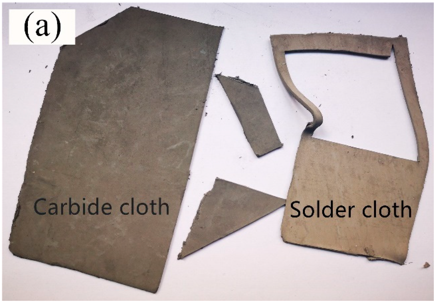
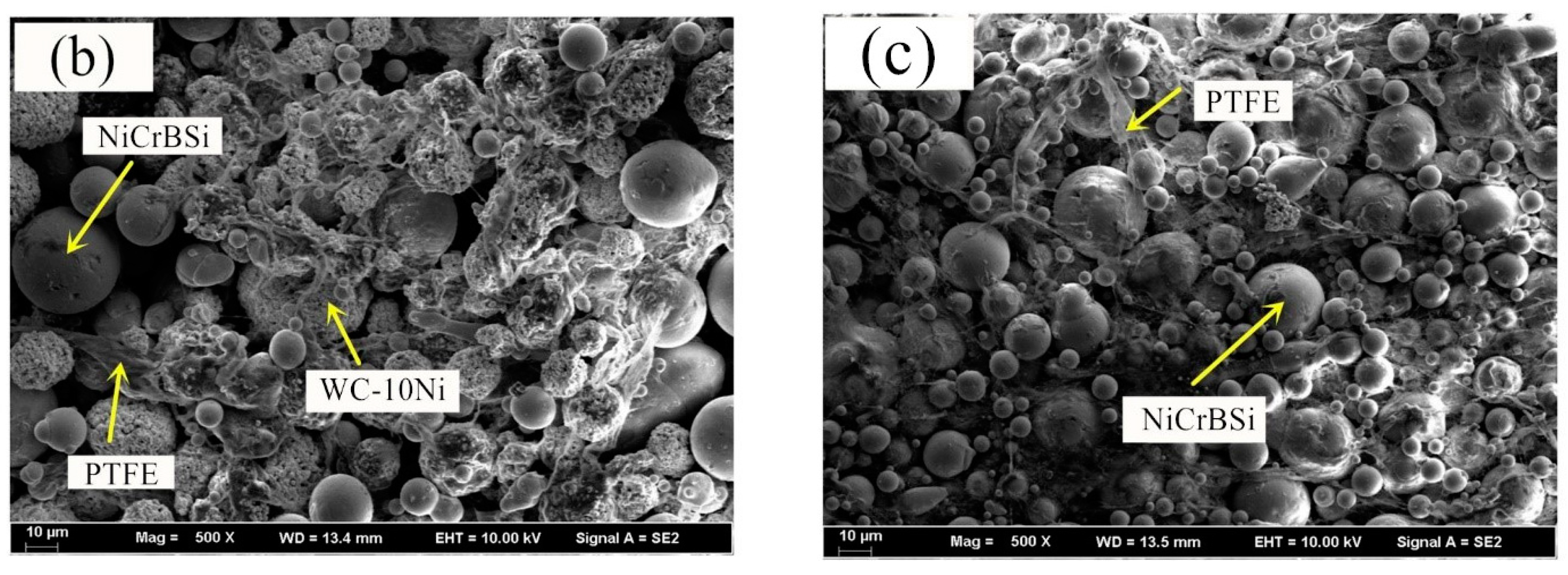
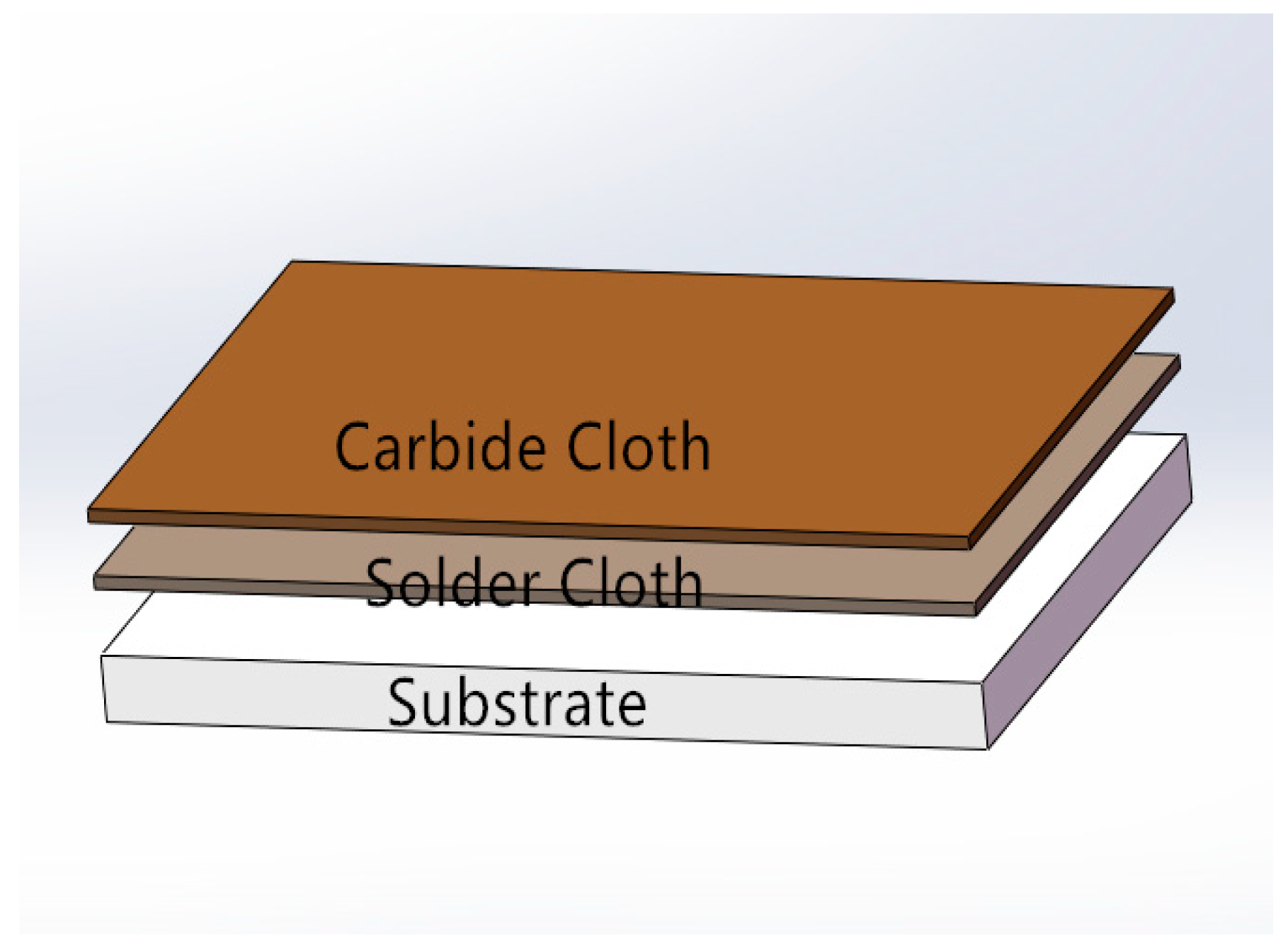
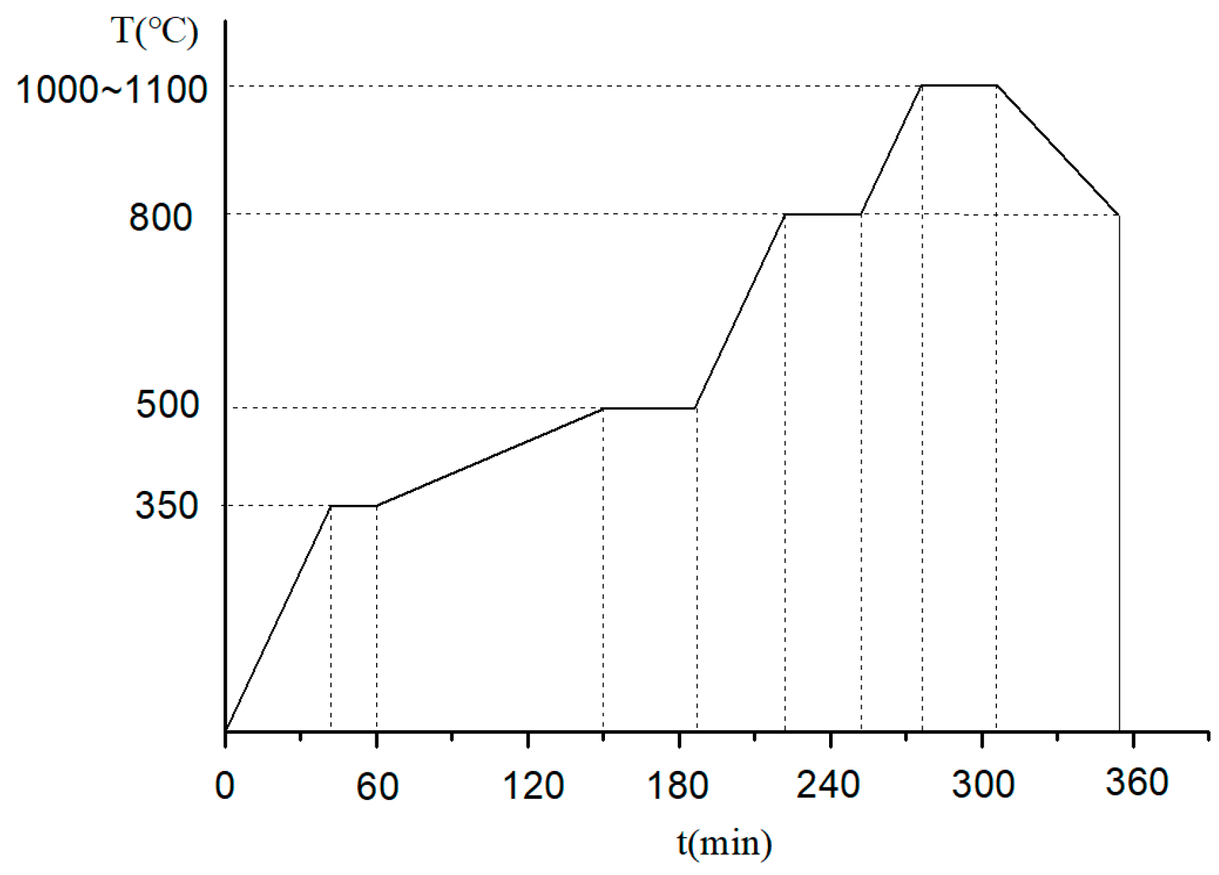
2.1. Materials and Coating Preparation Process
2.2. Micromorphology Characterizations
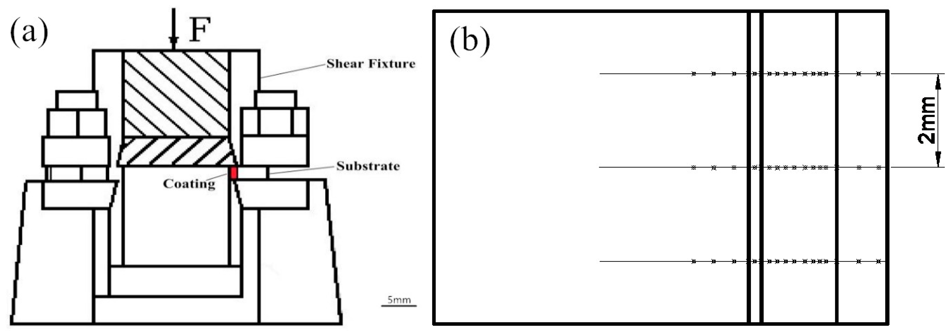
2.3. Hardness and Shear Test
2.4. Wear Resistance Test
3. Results
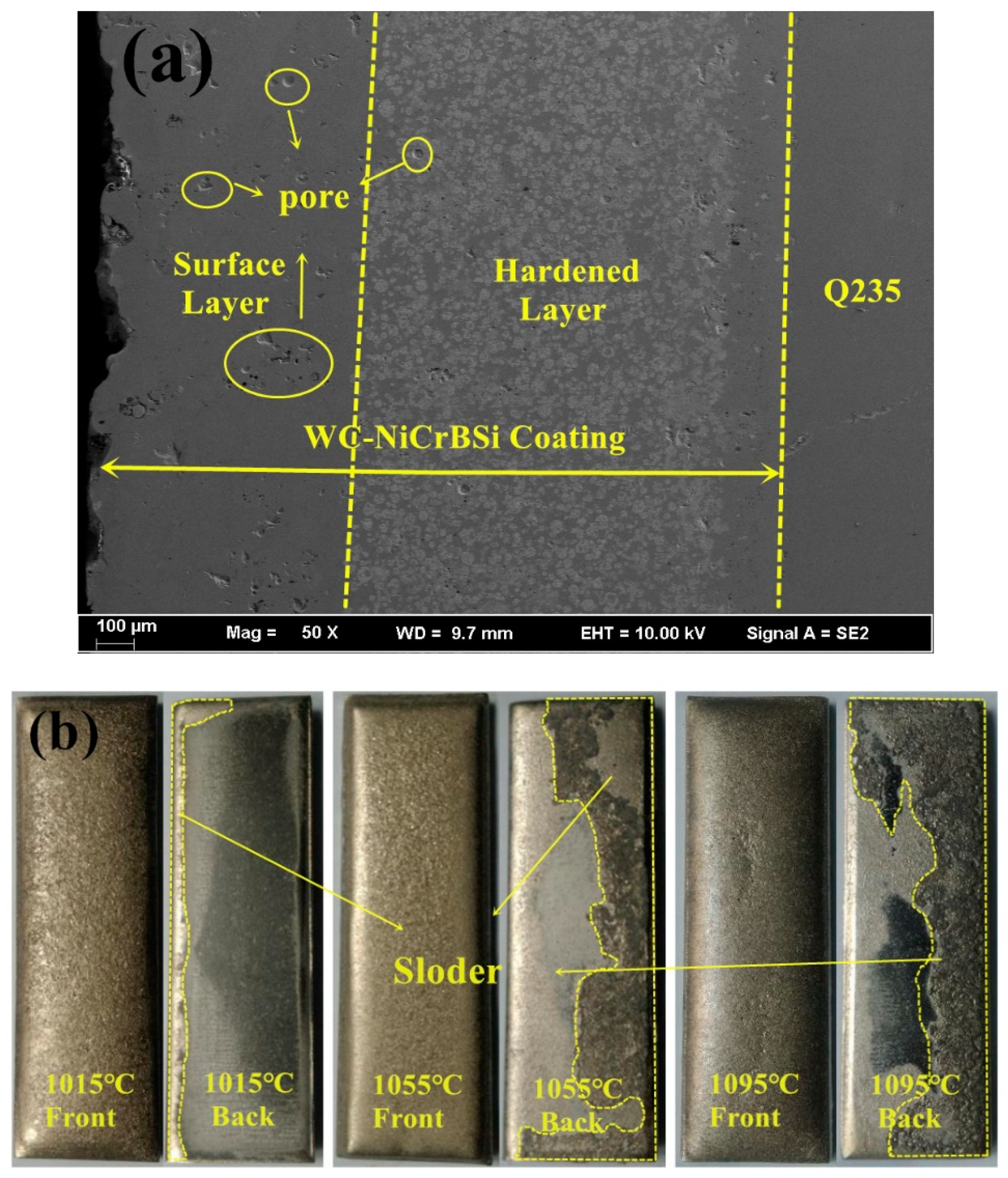
3.1. Microstructure
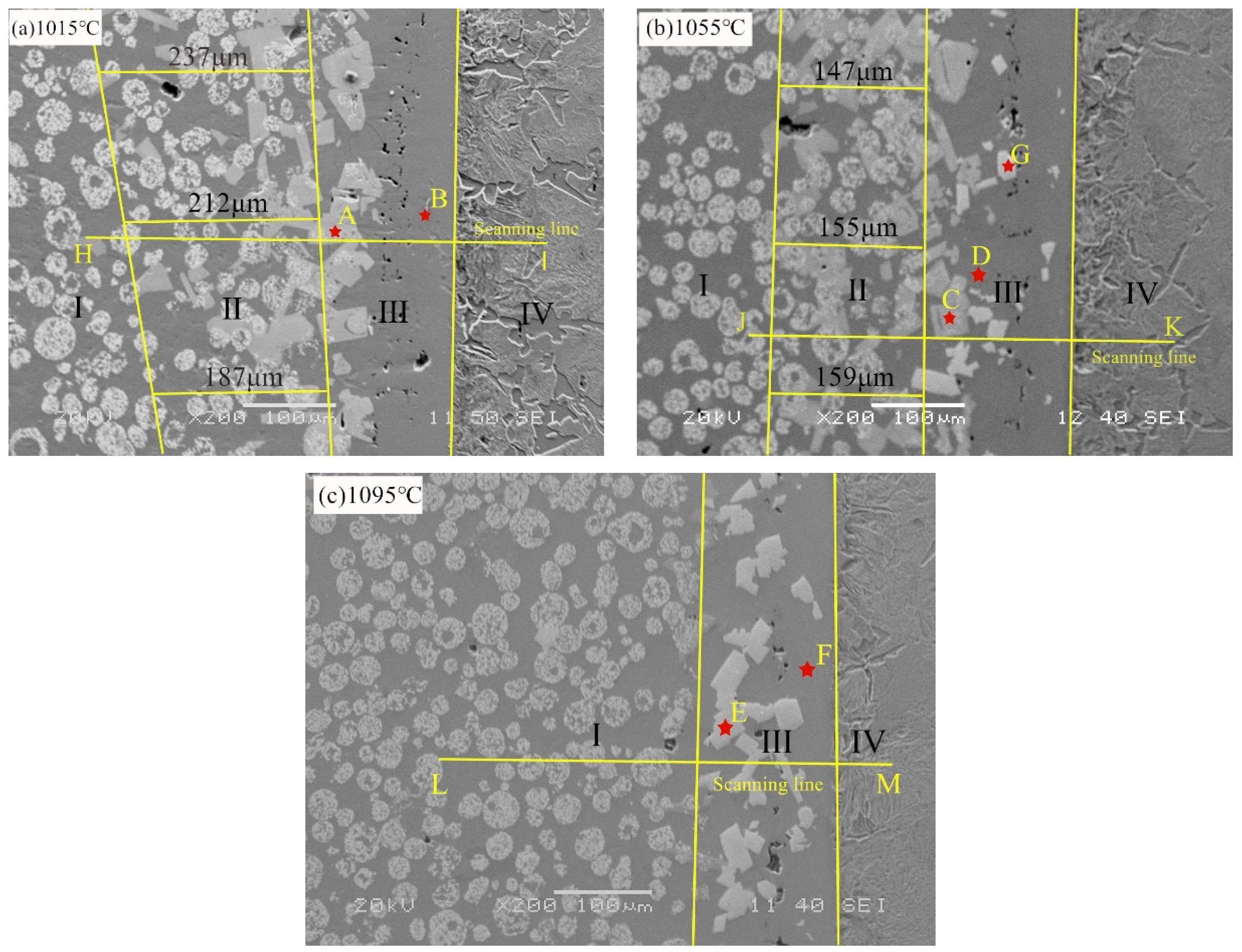
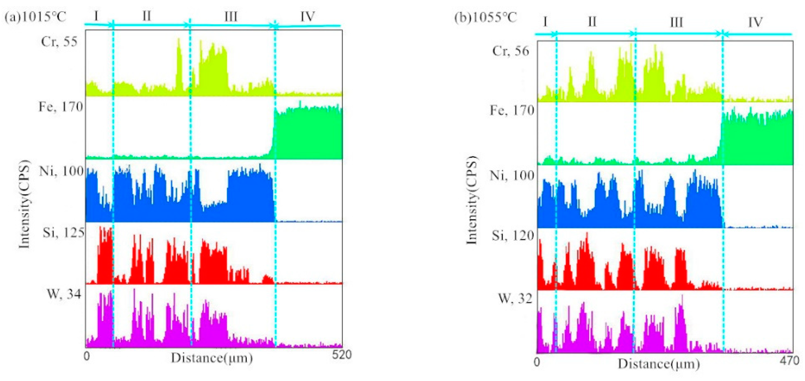
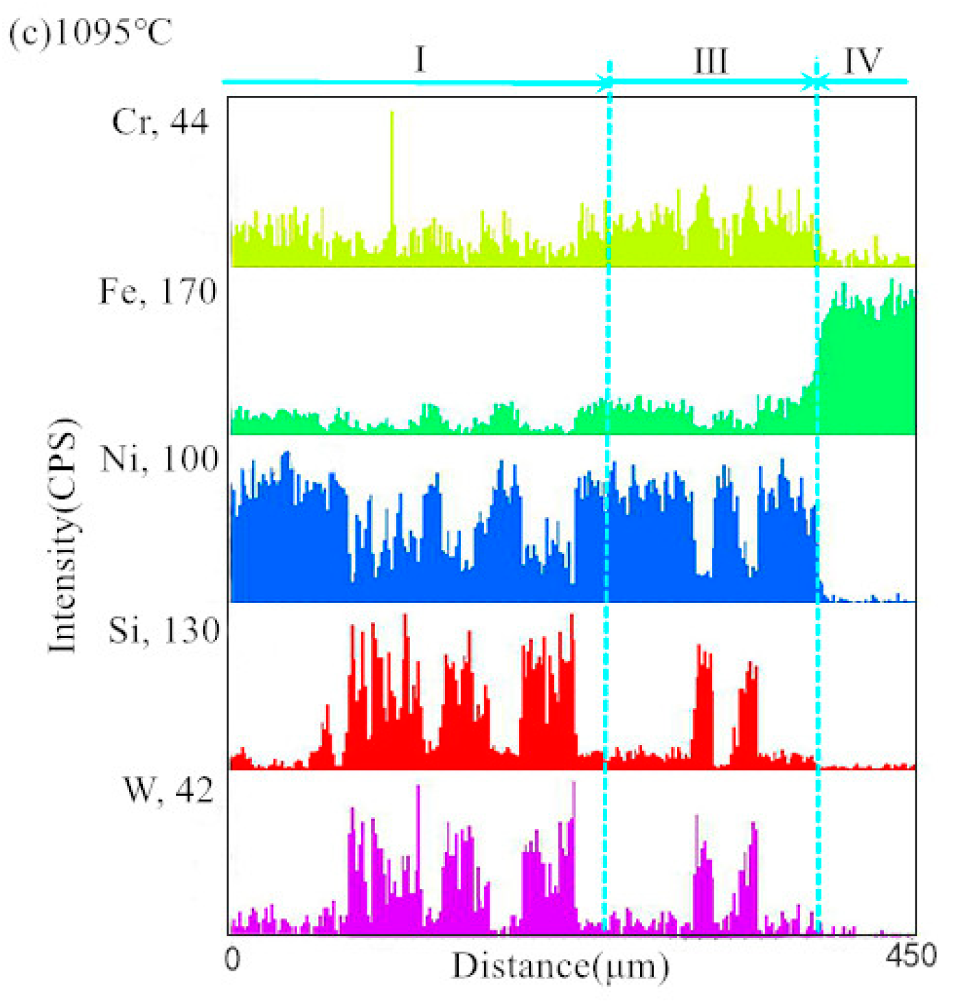
3.2. Interface Morphology and Element Distribution
3.3. Phase Composition of Composite Coating
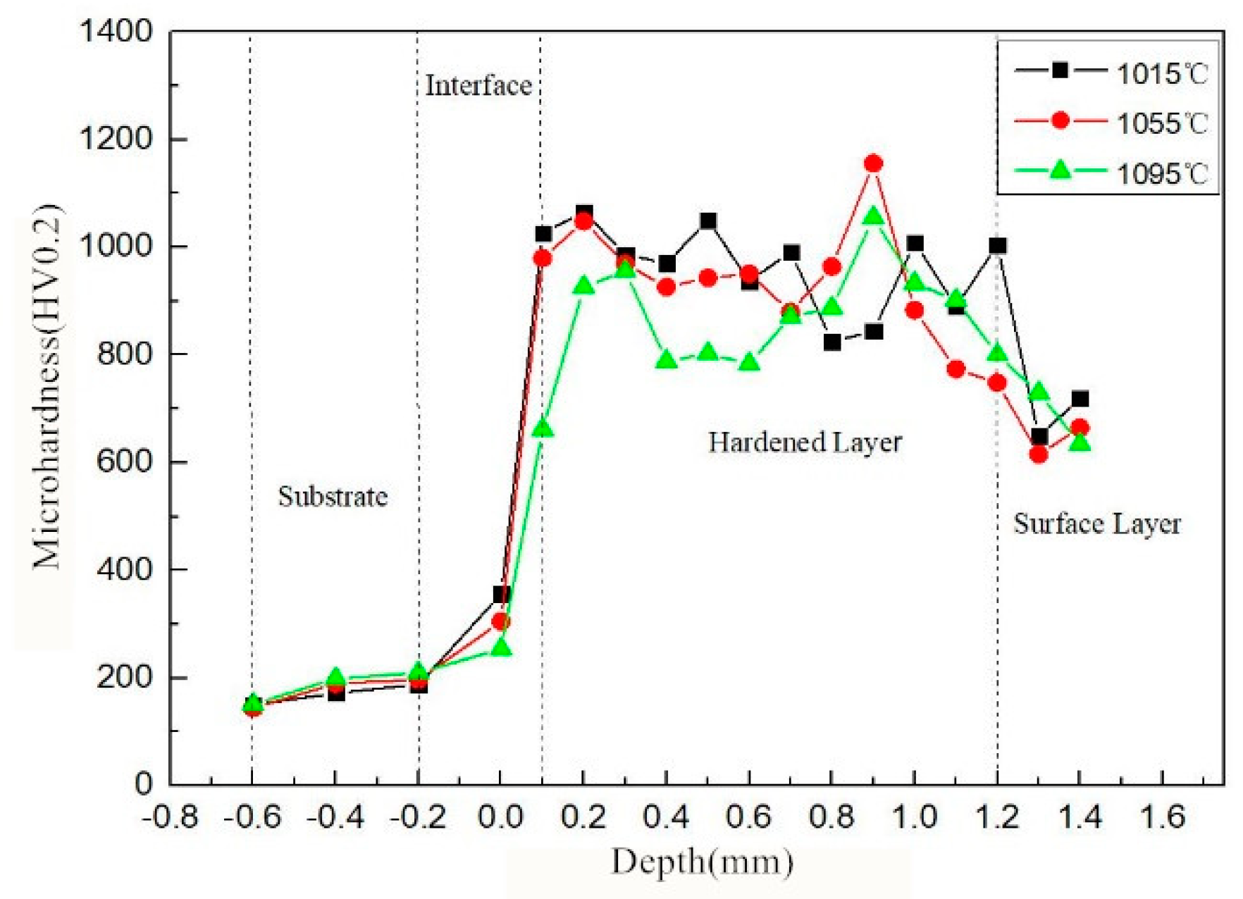
3.4. Microhardness of Composite Coating Sections
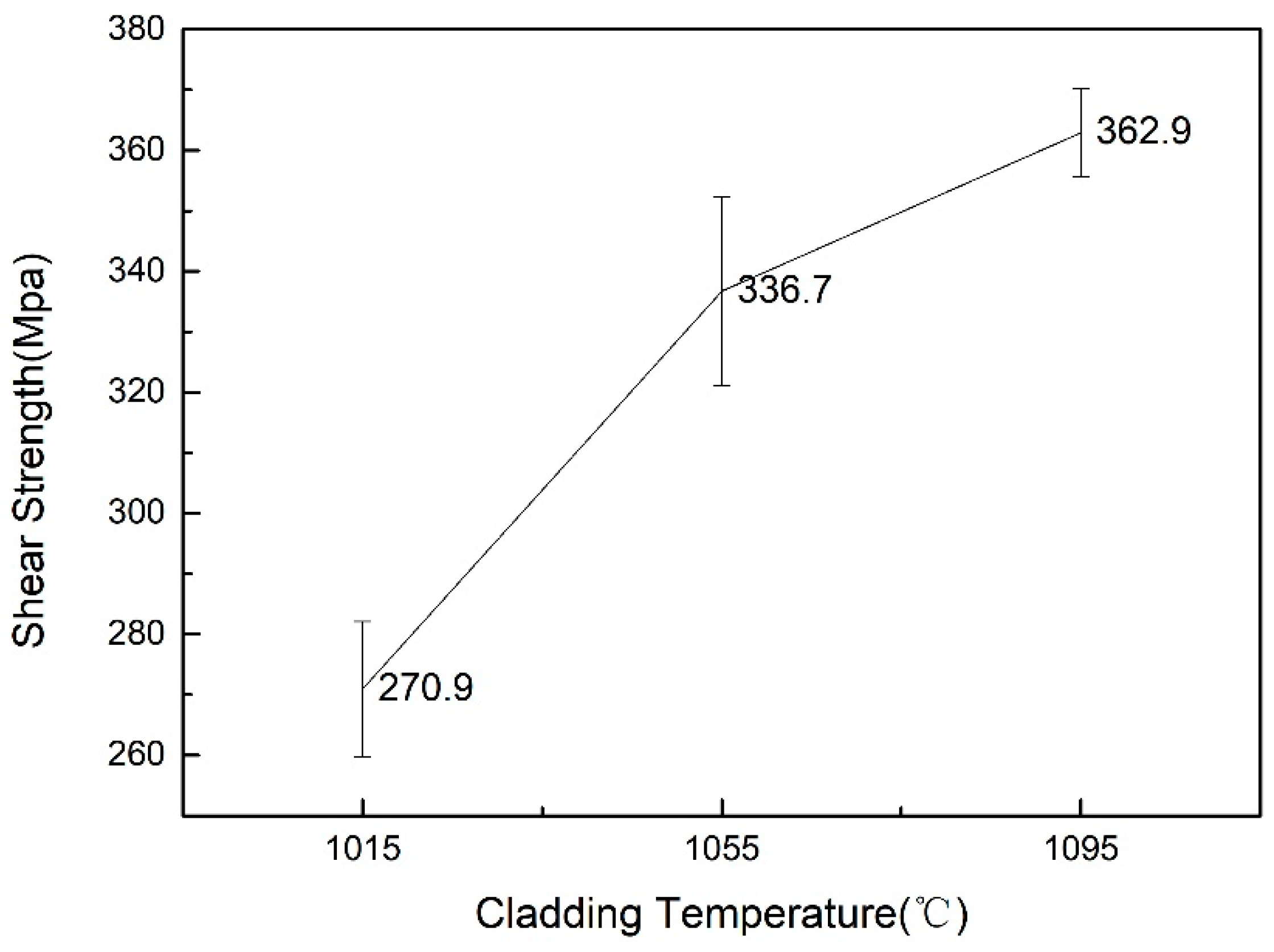
3.5. Bonding Strength between the Coating and Substrate
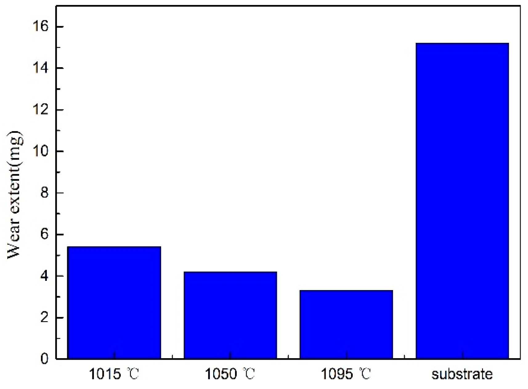
3.6. Wear Resistance of Composite Coating
4. Conclusions
- Three kinds of WC–10Ni/NiCrBSi composite coatings were prepared on the surface of Q235 carbon steel at 1015, 1055, and 1095 °C by vacuum brazing. Various reaction layers appeared at the bonding area of the coatings and the substrate. With the increase in brazing temperature, the reaction layer between the solder and the hard phase gradually decreased and disappeared at 1095 °C. Simultaneously, the size of gray-white massive phases with a large amount of W in the brazing layer decreased gradually.
- When the brazing temperature increased, the Fe content markedly increased in the reaction layer of the matrix and the solder. This indicated that the increase in brazing temperature was beneficial to metallurgical bonding between the coating and the matrix.
- Interface bonding strength and wear resistance were enhanced by the increase in brazing temperature. However, the microhardness of the composite coating section decreased. The interface bonding strength reached 362.9 MPa and the wear loss reached a minimum at 1095 °C.
Author Contributions
Funding
Conflicts of Interest
References
- Nahvi, S.M.; Jafari, M. Microstructural and mechanical properties of advanced HVOF-sprayed WC-based cermet coatings. Surf. Coat. Technol. 2016, 286, 95–102. [Google Scholar] [CrossRef]
- Liu, L.; Xu, H.; Xiao, J.; Wei, X.; Zhang, G.; Zhang, C. Effect of heat treatment on structure and property evolutions of atmospheric plasma sprayed NiCrBSi coatings. Surf. Coat. Technol. 2017, 325, 548–554. [Google Scholar] [CrossRef]
- Vashishtha, N.; Khatirkar, R.K.; Sapate, S.G. Tribological behaviour of HVOF sprayed WC–12Co, WC–10Co–4Cr and Cr3C2−25NiCr coatings. Tribol. Int. 2017, 105, 55–68. [Google Scholar] [CrossRef]
- Huang, S.; Sun, D.; Xu, D.; Wang, W.; Xu, H. Microstructures and Properties of NiCrBSi/WC Biomimetic Coatings Prepared by Plasma Spray Welding. J. Bionic Eng. 2015, 12, 592–603. [Google Scholar] [CrossRef]
- Bartkowski, D.; Bartkowska, A. Wear resistance in the soil of Stellite-6/WC coatings produced using laser cladding method. Int. J. Refract. Met. Hard Mater. 2017, 64, 20–26. [Google Scholar] [CrossRef]
- Alidokht, S.A.; Manimunda, P.; Vo, P.; Yue, S.; Chromik, R.R. Cold spray deposition of a Ni–WC composite coating and its dry sliding wear behavior. Surf. Coat. Technol. 2016, 308, 424–434. [Google Scholar] [CrossRef]
- Xu, X.P.; Liu, Q.M.; Xia, C.Z.; Zou, J.S. Microstructure and properties of Si3N4 ceramics and 304 stainless steel brazed joint with Cu/Ag-Cu/Ti laminated filler metal. High Temp. Proc. 2018, 37, 597–602. [Google Scholar] [CrossRef]
- Deschuyteneer, D.; Petit, F.; Gonon, M.; Cambier, F. Processing and characterization of laser clad NiCrBSi/WC composite coatings-Influence of microstructure on hardness and wear. Surf. Coat. Technol. 2015, 283, 162–171. [Google Scholar] [CrossRef]
- Dariusz, B.; Grzegorz, K. Microstructure and wear resistance of Stellite-6/WC MMC coatings produced by laser cladding using Yb: YAG disk laser. Int. J. Refract. Met. Hard Mater. 2016, 58, 157–164. [Google Scholar]
- Zou, J.S.; Jiang, Z.G.; Zhao, Q.Z.; Chen, Z. Brazing of Si3N4 with amorphous Ti40Zr25Ni15Cu20 filler. Mater. Sci. Eng. A 2009, 507, 155–160. [Google Scholar] [CrossRef]
- Xia, C.; Sun, W.; Zhou, Y.; Xu, X. Thermal fatigue damage and residual mechanical properties of W–Cu/Ag–Cu/1Cr18Ni9 brazed joint. J. Alloy. Compd. 2018, 741, 155–160. [Google Scholar] [CrossRef]
- Zou, J.; Liu, R.; Wang, L. Influence of Alloying Elements on Properties of Ti–Ni–Cu Brazing Alloys. Rare Met. Mater. Eng. 2010, 39, 1023–1026. [Google Scholar]
- Bailey, J.; Worden, D.; Breton, E.; Wolf, J. Coating metallic substrate with powdered filler and molten metal. U.S. Patent 3743556, 3 July 1973. [Google Scholar]
- Goldsmith, R. Method of preparing microporous tetrafluoroethylene resin sheets. U.S. Patent 3281511A, 25 October 1966. [Google Scholar]
- Lu, S.; Dong, X.; Wu, Q.; Guo, Y.; Xu, X.; Zhu, Z. Preparation of NiCrBSi–WC wear-resistant brazing coatings. J. Met. 1999, 35, 83–85. [Google Scholar]
- Tan, B.; Zhao, B.; Fan, J.; Gao, P. Study on the properties of WC “metal cloth” brazing wear layer by brazing temperature. Ordnance Mater. Sci. Eng. 2003, 254, 421–428. [Google Scholar]
- Li, H.; Jia, Y.; Xuan, F. Preparation and performance of gradient WC reinforced NiCrBSi alloy coating based on flexible metallic cloth technique. Mech. Eng. Mater. 2018, 42, 59–64. [Google Scholar] [CrossRef]
- Zhou, S.; Lei, J.; Dai, X.; Guo, J.; Gu, Z.; Pan, H. A comparative study of the structure and wear resistance of NiCrBSi/50 wt.% WC composite coatings by laser cladding and laser induction hybrid cladding. Int. J. Refract. Met. Hard Mater. 2016, 60, 17–27. [Google Scholar] [CrossRef]
- Grunder, T.; Piquerez, A.; Bach, M.; Mille, P. Residual Stress in Brazing of Submicron Al2O3 to WC–Co. J. Mater. Eng. Perform. 2016, 25, 2914–2921. [Google Scholar] [CrossRef]
- Pascal, D.T.; Şerban, V.A.; Marginean, G. Optimization of process parameters for the manufacturing of high temperature vacuum brazed WC–NiCrBSi Coatings. Solid State Phenom. 2016, 254, 164–169. [Google Scholar] [CrossRef]
- Ortiz, A.; García, A.; Cadenas, M.; Fernández, M.R.; Cuetos, J.M. WC particles distribution model in the cross-section of laser cladded NiCrBSi + WC coatings, for different wt % WC. Surf. Coat. Technol. 2017, 324, 298–306. [Google Scholar] [CrossRef]
- Ramirez, C.; Ismail, A.I.; Gendarme, C.; Dehmas, M.; Aeby-Gautier, E.; Poulachon, G.; Rossi, F. Understanding the diffusion wear mechanisms of WC–10%Co carbide tools during dry machining of titanium alloys. Wear 2017, 390, 61–70. [Google Scholar] [CrossRef]


| Material | Density (cm3) | Elastic Modulus (GPa) | Poisson’s Ratio | Tensile Strength (MPa) | Yield Strength (MPa) |
|---|---|---|---|---|---|
| Q235 | 7.85 | 200–210 | 0.25–0.33 | 370–500 | 235 |
| Chemical Composition | Cr | B | Si | C | Fe | P | Ni |
|---|---|---|---|---|---|---|---|
| Mass fraction | 6.0–8.0 | 2.75–3.5 | 4.0–5.0 | 0.06 | 2.5–3.5 | 0.02 | 79.92–84.67 |
| Metal Cloth Type | WC–10Ni (5–15 μm) | WC–10Ni (30–45 μm) | NiCrBSi | PTFE |
|---|---|---|---|---|
| carbide cloth | 3 | 3 | 4 | 0.16 |
| solder cloth | – | – | 10 | 0.16 |
| Representative Points | Elemental Composition(wt.%) | ||||
|---|---|---|---|---|---|
| Si | Cr | Fe | Ni | W | |
| A | 5.0 | 22.8 | 1.4 | 27.8 | 43.1 |
| C | 5.1 | 21.2 | 0.7 | 25.6 | 47.4 |
| E | 7.9 | 11.1 | 1.7 | 15.5 | 63.8 |
| G | 9.0 | 7.1 | 2.1 | 13.4 | 68.5 |
| B | 9.2 | 7.3 | 7.1 | 76.3 | – |
| D | 8.8 | 5.6 | 16.3 | 69.4 | – |
| F | 8.6 | 5.5 | 19.6 | 66.3 | – |
© 2019 by the authors. Licensee MDPI, Basel, Switzerland. This article is an open access article distributed under the terms and conditions of the Creative Commons Attribution (CC BY) license (http://creativecommons.org/licenses/by/4.0/).
Share and Cite
Xu, X.; Ding, H.; Xia, C.; Zou, J.; Wang, Y. Effect of Brazing Temperature on the Microstructure and Chosen Properties of WC–10Ni/NiCrBSi Composite Coatings Produced by Vacuum Cladding from Flexible Coated Cloths. Coatings 2019, 9, 214. https://doi.org/10.3390/coatings9040214
Xu X, Ding H, Xia C, Zou J, Wang Y. Effect of Brazing Temperature on the Microstructure and Chosen Properties of WC–10Ni/NiCrBSi Composite Coatings Produced by Vacuum Cladding from Flexible Coated Cloths. Coatings. 2019; 9(4):214. https://doi.org/10.3390/coatings9040214
Chicago/Turabian StyleXu, Xiangping, Hengnan Ding, Chunzhi Xia, Jiasheng Zou, and Yi Wang. 2019. "Effect of Brazing Temperature on the Microstructure and Chosen Properties of WC–10Ni/NiCrBSi Composite Coatings Produced by Vacuum Cladding from Flexible Coated Cloths" Coatings 9, no. 4: 214. https://doi.org/10.3390/coatings9040214