Article

Multifunctional Protective PVC-ZnO Nanocomposite Coatings Deposited on Aluminum Alloys by Electrospinning

1
Materials Engineering Laboratory, Department of Engineering, Public University of Navarre, Campus Arrosadía S/N, 31006 Pamplona, Spain
2
Institute for Advanced Materials (InaMat), Public University of Navarre, Campus Arrosadía S/N, 31006 Pamplona, Spain
3
Centre of Advanced Surface Engineering, AIN, 31191 Cordovilla, Spain
*
Author to whom correspondence should be addressed.
Coatings 2019, 9(4), 216; https://doi.org/10.3390/coatings9040216
Submission received: 8 March 2019 / Revised: 22 March 2019 / Accepted: 25 March 2019 / Published: 27 March 2019

Abstract

:
This paper reports the use of the electrospinning technique for the synthesis of nanocomposite micro/nanofibers by combining a polymeric precursor with hydrophobic behavior like polyvinyl chloride (PVC) with nanoparticles of a corrosion inhibitor like ZnO. These electrospun fibers were deposited on substrates of the aluminum alloy 6061T6 until forming a coating around 100 μm. The effect of varying the different electrospinning deposition parameters (mostly applied voltage and flow-rate) was exhaustively analyzed in order to optimize the coating properties. Several microscopy and analysis techniques have been employed, including optical microscopy (OM), field emission scanning electron microscopy (FE-SEM), atomic force microscopy (AFM), thermogravimetric analysis (TGA), and differential scanning calorimetry (DSC). Water contact angle (WCA) measurements have been carried out in order to corroborate the coating hydrophobicity. Finally, their corrosion behavior has been evaluated by electrochemical tests (Tafel curves and pitting potential measurements), showing a relevant improvement in the resultant corrosion resistance of the coated aluminum alloys.

1. Introduction

Aluminum alloys are widely used in many industrial areas such as automotive, aerospace, and construction, due to their physical and mechanical properties: Low density, good mechanical properties at low temperatures, good corrosion resistance, and excellent thermal and electrical conductivities [1]. While aluminum is a very reactive metal with a high affinity for oxygen, the metal shows a high corrosion resistance in most environments. This is due to the thin layer of aluminum oxide (Al2O3) that is formed on the surface of the metal. This passive layer, of around 5 to 10 nanometers thick, shows an inert and protective character and acts as a barrier between the metal and the surrounding medium. However, in spite of this passive layer, Al and its alloys can still suffer corrosion when they are exposed to aggressive corrosive media like those containing chloride ions [2]. In order to extend the range of applications of these alloys, it is necessary to extend their corrosion resistance by means of surface treatments or coatings with the aim to reduce the economic impact of corrosion [3].
A widely used anti-corrosion practice for metals is the implementation of barrier coatings, which consists of covering the metallic surface with a protective film that acts as a barrier and avoids the direct interaction between the metal and the environment. Traditional coatings containing Cr and Pb have been banned in many countries because they are a threat for human health. This is why the development of ecofriendly polymeric coatings has gained special interest nowadays [4]. In particular, a technique that is increasing in popularity in the last few years is electrospinning due to its relative ease of use and because it allows the deposition ultrafine polymeric fibers over a metallic surface that can act as an effective barrier coating and reduce the corrosion rate of the metal.
Recently, superhydrophobic (SH) coatings with water contact angle (WCA) higher than 150° have gained special interest due to their excellent water repellency properties. These SH coatings can be used to improve the corrosion resistance of Al and Al alloys as they minimize the contact area between the metallic surface and the corrosive electrolyte. SH surfaces can be produced by increasing the roughness of the surface for the target material [5,6,7]. Electrospinning is a powerful technique for developing SH coatings because the electrospun micro/nanofibers form a film that presents a surface roughness high enough to provide hydrophobic or even superhydrophobic behavior [8,9]. In addition, electrospun coatings can be obtained in a short period of time by using only one step and the diameter thickness of the resultant fibers can be perfectly controlled from nanometric to micrometric scale by changing the fabrication parameters (applied voltage, flow rate, and distance collector) as well as the resultant viscosity of the precursor, respectively
Corrosion resistance can be further enhanced by the addition of a corrosion inhibitor, either organic or inorganic. Many researchers have focused on blending a polymer with inorganic nanoparticles, such as Al2O3, ZrO2, SiO2, TiO2, Fe3O4, CdS, and ZnO, among others [10,11,12,13,14,15,16,17,18,19]. The presence of these nanoparticles between the interstices of the fibers can increase the surface roughness and the air entrapment, improving the hydrophobic character of the coating and thus reducing the corrosion rate.
In this work, polyvinyl chloride (PVC) was the polymer chosen for the development of anticorrosion electrospun coatings because it is a polymer with hydrophobic behavior by nature, and zinc oxide (ZnO) nanoparticles were used as the corrosion inhibitor because the corrosion behavior of electrospun PVC-ZnO, to the best of our knowledge, has not been addressed previously. PVC-ZnO nanofibers were successfully deposited onto aluminum 6061T6 substrates by electrospinning and the corrosion behavior of the nanocomposite film was exhaustively analyzed.

2. Experimental Procedure

2.1. Reagents and Materials

Polyvinyl chloride (PVC, (C2H3Cl)n, Mw = 80,000 g/mol), dimethylformamide (DMF) and tetrahydrofuran (THF) were purchased from Sigma-Aldrich (Saint Louis, MO, USA). Zinc oxide (ZnO) nanoparticles in colloidal dispersion (50% in H2O) with average particle size of 50 nm were purchased from Alfa Aesar (Haverhill, MA, USA). All reagents used without further purification. The coatings have been performed onto aluminum substrates of the alloy AA6061T6.

2.2. Deposition of PVC-ZnO Nanocomposite Coatings

PVC was dissolved in a 1:1 solvents mixture of THF and DMF, thus obtaining a homogeneous PVC solution with polymer concentration 15 wt %, respectively. The viscosity of the solvents was 0.92 mPa·s for DMF and 0.55 mPa·s for THF, respectively. An important aspect to remark is that the final solution viscosity depends on the polymer concentration and the volume ratio between the solvents [20,21]. The solution was prepared under vigorous stirring (600 rpm) for 12 h at room temperature by using a magnetic stirrer. Separately, 0.64 g of the zinc oxide colloidal dispersion was added to a mixture of 1 mL of THF and 1 mL of DMF (same 1:1 solvent volume ratio as the polymer solution). This ZnO mixture was produced and dispersed applying stirring (200 rpm) for 12 h at room temperature. Afterwards, the dispersed ZnO mixture was added to the PVC solution, and then vigorous stirring (600 rpm) was applied for 2 h in order to allow for an adequate mixing.
The PVC-ZnO solution was then electrospun using ND-ES 11/7 Lab Electrospinning Unit (Nadetech Innovations S.L., Navarre, Spain). A horizontal configuration with fixed collector was used, and the capillary tip was located 15 cm away from the aluminum electrode that was used as the collector. A 20-gauge needle with an inner diameter specific of 0.6 mm has been used for all the experiments. Electrospinning experiments were conducted at various pump speeds and direct current (DC) voltages in order to optimize the values of flow rate and applied voltage that allow for the fabrication of very thin fibers with maximum water repellency. Finally, in all the experiments the electrospinning process was conducted at room temperature (20 °C) at 40% relative humidity and the deposition time was fixed for a period of time of 10 min, respectively.

2.3. Characterization Techniques

Optical microscopy (OM, BX60M, Olympus, Tokyo, Japan) was used for a first observation of fiber morphology and for estimating the average fiber diameter. Field emission scanning electron microscopy (FE-SEM, S4800, Hitachi, Tokyo, Japan) and atomic force microscopy (AFM, Veeco Innova AFM, Veeco Instruments, Plainview, NY, USA) were employed for a more exhaustive analysis of the fiber size, morphology and surface roughness.
Water contact angle (WCA) measurements were conducted on a CAM 100 contact angle goniometer (CAM 100, KSV Instruments, Burlington, VT, USA) using distilled water. The static water contact angle was measured 5 times at different sites and the representative samples were chosen to present the result.
The composition of the films was controlled by thermal gravimetric analysis (TGA, Q500, TA Instruments, New Castle, DE, USA), and differential scanning calorimetry (DSC, DSC25, TA Instruments, New Castle, DE, USA) was used for studying the thermal properties of the coatings. DSC tests were performed starting from an equilibrium temperature of −80 °C and raising 10 °C per minute up to a final temperature of 200 °C. In addition, the adhesion of the coating has been determined by applying a pressure-sensitive adhesive tape onto a grid of small squares previously formed. The fraction of coating removed from the grid when the adhesive tape is removed is compared with standard ratings.
Electrochemical measurements including Tafel polarization curves and pitting corrosion tests were carried out on an Autolab Potentiostat/Galvanostat PGSTAT302N (Metrohm, Herisau, Switzerland). All corrosion tests were performed at room temperature in 3.5 wt % NaCl aqueous solutions, using a conventional three electrode cell consisting of a working electrode (bare or coated Al sample), a silver chloride Ag-AgCl reference electrode and a platinum counter electrode. Before conducting all the experiments, the samples were immersed in the 3.5 wt % NaCl electrolyte for 30 min to make sure that the system is in steady state. Tafel polarization measurements were obtained by scanning the electrode potential automatically from −150 to +150 mV at a scan rate of 1.5 mV·s−1. The corrosion protection efficiency from Tafel polarization curves was calculated by the following formula [22,23]:
η = i c o r r i c o r r ( C ) i c o r r × 100 %
In this equation, icorr and icorr(C) correspond to the corrosion current densities of bare aluminum and coated aluminum, respectively.
For the pitting corrosion tests the measurements were obtained by scanning the electrode potential from 0 to +2 V at a scan rate of 0.15 mV·s−1, and reversing the scan direction once the current reaches a cutoff value of 2.5 mA.

3. Results and Discussion

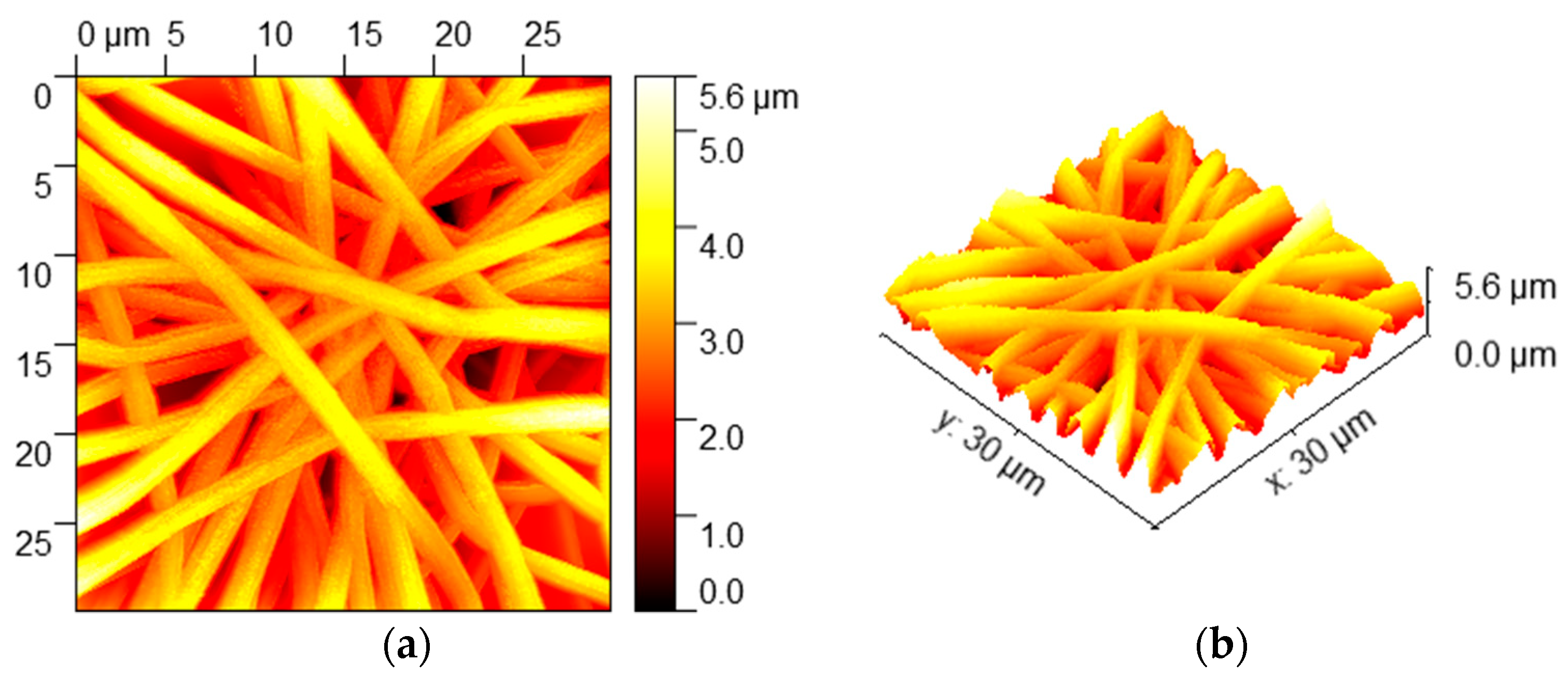
3.1. Morphologies and Wettability

The first step was the optimization of the electrospinning parameters, mainly applied voltage (E) and flow rate. These two are the processing parameters that have a bigger impact on the final morphology of the resultant fibers. Several samples of PVC were electrospun under different electrospinning conditions, varying these two parameters. Firstly, the lower and upper limit values of the electric potential that can be applied for a successful deposition need to be determined. Voltage values of 6 kV and lower showed to be too low and no fibers were deposited. There is also an upper limit for E above which the Taylor cone is no longer formed and the fiber jet is ejected from within the needle, which is associated with an increase in fiber defects [24]. The Taylor cone was observed to be formed in the range of 8–14 kV. These values were chosen to be the lower and upper limits of the applied voltage for the set of experiments of the parameter optimization process. In Figure 1a it can be seen that fiber diameter of PVC electrospun fibers decreases when increasing the applied voltage, which goes in accordance with the results obtained by Lee et al. [25]. This may be explained by an increase in the electrostatic repulsive force on the charged jet narrowing the fiber diameter. In addition, Figure 1b shows that the resultant fiber diameter gets bigger when increasing the flow rate, as expected, which is in concordance with literature [24,26]. Other aspects to remark is that, despite the variation of fiber diameter, no remarkable differences in morphology were observed when applying different voltages and flow rates.
Once it has been evaluated the effect of the experimental parameters on the resultant fiber diameter, the PVC-ZnO fibers in this work have been electrospun under 14 kV and a flow rate of 0.6 mL·h−1 because there are scientific studies which indicate that there is an increase in the hydrophobicity caused by a reduction in diameter among bead-free fibers [27]. Figure 2 shows SEM micrographs revealing the morphology of PVC-ZnO nanocomposite fibers with different image amplifications. It can be clearly seen that the resultant electrospun nanofibers present relatively uniform fibers whose average diameter was measured to be around 720 nm.
In order to corroborate the presence of zinc oxide into the electrospun nanofibers, the composition of the nanocomposite fibers (PVC-ZnO) has also been analyzed by using a thermal gravimetric analysis (TGA), as it can be appreciated in Figure 3. First of all, the TGA thermogram obtained from blank films (only PVC without ZnO) showed two consecutive weight losses (solid line) around 345 and 490 °C, whereas no further weight loss has been observed for higher values of temperature. However, the sample composed of PVC-ZnO nanoparticles showed a third weight loss around 530 °C (dash-dotted line), which corresponds to the amount of ZnO nanoparticles (1.34% in weight) into the electrospun PVC fibers.
The surface wettability of the PVC-ZnO nanocomposite coating was assessed performing water contact angle (WCA) measurements. In Figure 4, representative optical images of water droplets deposited onto both PVC and PVC-ZnO electrospun fiber mats are shown. It is worthy to mention that similar contact angle values in the range of 145°–155° have been measured over both samples, so no significant differences in the wettability have been observed between the samples composed of ZnO nanoparticles in comparison with only PVC samples.
Low adhesive forces were noticed between the PVC-ZnO nanocomposite substrate and water droplets, which may be attributed to the high surface roughness of the fibrous mat. Initially, the wetting of rough surfaces was explained by the Wenzel [28], or the Cassie-Baxter or models [29]. This later model states that surface superhydrophobicity is caused by the air entrapment underneath the liquid inside the grooves. In the Cassie-Baxter state, the contact angle of a water droplet on a hydrophobic surface (θc) is related to the contact angle on a smooth surface (θ) by the following equation:
cos ( θ c ) = f 1 cos ( θ ) f 2
In this equation f 1 and f 2 are proportions of solid surface and air in contact with liquid, respectively. In addition, f 1 + f 2 = 1.
More recently, both, the Wenzel and the Cassie-Baxter models have been revised and, in some extent, highly criticized [30,31]. In most of published papers about wettability of electrospun coatings, authors employ the Cassie-Baxter model to explain the main features [32], although mixed states and transitions between both phases have been reported [33,34]. In particular, the effects of fiber diameter, fiber density and liquid surface tension are taken in account. In general, the air trapped between fibers keeps the wetting behavior in the Cassie-Baxter regime, but transitions to the Wenzel state are reported for liquids with surface tension below 58 mN·m−1, which is not the case in water [35].
Assuming a fair validity of the Cassie-Baxter model, as the contact angle value of the PVC-ZnO nanocomposite coating was found to be θc = 147°, their equation provides a value for f 2 of, approximately, 0.84. This means that about 84% of the water drop is in contact with air, and only 16% is in contact with the solid surface. Such hydrophobic behavior is desired in an anticorrosion coating because, if there is small contact area between the electrolyte and the metal, a less amount of aggressive ions will attack the metallic surface.
Atomic force microscopy was used in order to examine the morphology and to determine the surface roughness of the prepared electrospun nanocomposite coatings. In Figure 5 is shown in 2-dimensional (2D) and 3-dimensional (3D) AFM images the PVC-ZnO nanocomposite coating electrospun at 14 kV and a flow rate of 0.6 mL·h−1. In addition, the surface roughness was investigated with AFM by measuring 3 evaluation lines which are presented in Figure 6. It was observed that the average roughness Ra of the PVC-ZnO coating is 427.5 nm.

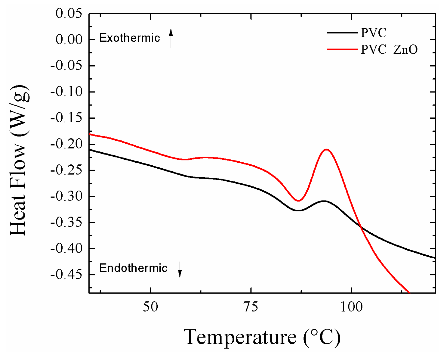
3.2. Effect of Heat Treatment on Hydrophobicity

In this work the behaviour of the coatings after a thermal treatment was studied. The main limitation found for the electrospun coatings is their low adherence to the substrate. This can be an obstacle for the implementation of this technique in industrial applications. One effective way to increase the adherence of the fiber mat onto the substrate is to perform a thermal treatment. Homaeigohar et al. found that heating of electrospun polyethersulfone fibers (PES) improves adhesion between the electrospun fibers and the underlying substrate [36]. Furthermore, several studies have shown that heat treatment is able to increase the mechanical strength of the electrospun mat. The reason for this may be that heat treatment encourages fusion at the contact points between fibers, providing a strengthening effect [37]. In this work, a crosshatch test has been also performed in order to corroborate this increase in the resultant adhesion onto the underlying substrate after thermal treatment. Firstly, on one hand, when the cutting tool was applied onto the non-heat treated coating, the electrospun fiber mat was heavily damaged, being impossible to perform the crosshatch test. However, on the other hand, when the electrospun coating has been thermally treated, the resultant fiber film has been not been destroyed when performing the crosshatch test. In addition, the electrospun coating still showed a low adhesion onto the aluminum substrate because more than 65% of the area was removed when pulling off the tape.
Heat treatment is usually carried out between the glass transition temperature (Tg) and the melting temperature (Tm) of the material [38]. The application of a heat treatment to the PVC electrospun coating was performed with two different goals: (1) Increasing the adhesion between the fibers and the underlying substrate and (2) checking the hypothesis that heating the sample above Tg would improve the ZnO nanoparticles distribution be to an improvement in tween the fibers due to the movement and vibrations of the polymer chains, thus leading the corrosion resistance of the coating. The glass transition temperature of PVC was determined using differential scanning calorimetry (DSC). Figure 7 shows the DSC plots of the PVC electrospun samples with and without ZnO nanoparticles inclusions. Results showed that the addition of ZnO nanoparticles produced an increment in the amount of heat required to increase the temperature of the electrospun samples, but the shape of the graphs (heat flow versus temperature) remained almost equal. This means that the presence of ZnO nanoparticles in between the fiber mat does not produce a relevant change in the thermal behaviour of PVC fibers. The glass transition temperature of PVC and PVC-ZnO was found to be 82.27 and 82.36 °C respectively. An aspect to remark is that glass transitions can sometimes be confused with an endothermic transition due to the occurrence of molecular relaxation processes in the material. In Figure 7, DSC curves exhibited these molecular relaxation processes related to the glass transition.
The effects of heat treatment on the WCA values of electrospun PVC fibers at 60, 70, 80, 90, 100, 110 and 120 °C were studied. All heat treatments were performed in an industrial oven during 1 h. In Table 1, the WCA values of PVC fibers obtained at the different temperatures is presented.
The contact angle values of PVC fibers started to decrease after surpassing the glass transition temperature of the polymer (i.e., 80 °C) reaching a minimum WCA value of 120° after the final heat treatment at 120 °C. Representative images of this behaviour can be observed in Figure 8. The experimental results are in accordance with the ones obtained by Asmatulu et al. [39]. The change in the contact angle values may be related to the rearrangement of the fiber structures in the film at the glass transition temperature. Below Tg polyvinyl chloride is a glassy solid and the polymer chains are rigid and cannot move. Above Tg the polymer chains start moving and vibrating, and the film becomes softer and rubbery, which may produce this decrease in the water contact angle values.

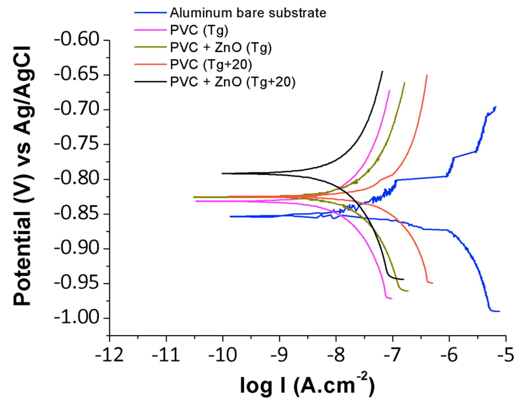
3.3. Anticorrosion Performance of PVC-ZnO Nanostructures

The main objective of this work was the electrospinning of polymer coatings with the aim of improving the corrosion resistance of aluminum substrates. In order to check if the electrospun PVC and PVC-ZnO nanocomposite films successfully enhance this corrosion resistance, Tafel polarization and pitting corrosion tests were held. Firstly, corrosion tests were performed over the bare aluminum 6061T6 without any coating. Results are shown in Figure 9. The Tafel analysis showed that the corrosion current density (icorr) for the bare aluminum substrate was 1.107 μA·cm−2 at a corrosion potential (Ecorr) of −0.856 V, and the cathodic (βc) and anodic (βa) Tafel constants were found to be 150 and 56 mV/decade, respectively. The pitting corrosion curve provides information about the bare aluminum behaviour against localized (pitting) corrosion. Scully et al. defined the pitting potential (Ep) as the potential above which the rising current permanently exceeded 10 µA [40]. Therefore following that definition the pitting potential of the bare aluminum sample was found to be −0.656 V.
After corrosion tests were successfully conducted over the reference bare Al sample, the corrosion behaviour of aluminum coated with the electrospun polymer films was studied in order to see if there was an improvement in the corrosion resistance of the metallic substrate with the use of these nanocomposite coatings. For testing the corrosion resistance of electrospun PVC films in the presence and absence of ZnO nanoparticles inclusions, corrosion tests were performed over samples after being heated up to the glass transition temperature (Tg) due to the improved adherence of the fiber mat with the metallic substrate, and also over samples heated 20 °C over this temperature (Tg + 20) in order to check the hypothesis that a better distribution of ZnO nanoparticles caused by the movement of the polymer chains above Tg could compensate the contact angle decrease and improve the corrosion resistance of the coating. The Tafel plots are displayed in Figure 10 and results are summarized in Table 2, respectively.
The results show that all electrospun coatings reduced the corrosion current density of aluminum in two orders of magnitude. This corrosion resistance was lowered significantly from 1.107 µA·cm−2 in the case of bare Al to a minimum of 0.009 µA·cm−2 in case of Al/PVC-ZnO after being heat treated to 100 °C (Tg + 20). The corrosion potential was displaced towards less negative values, attaining a maximum of −0.793 V in the case Al/PVC-ZnO (Tg + 20) again. The protection efficiency (η) in the case of pure PVC after being heat-treated to 80 °C (Tg) was found to be 99.01%. When the pure PVC coating was heated to 100 °C the efficiency was reduced to 97.38%, which can be explained by the decrease in the water contact angle when surpassing the glass transition temperature of the polymer. The composite coating of PVC-ZnO presented lower efficiency than the other samples when heated to Tg, but it was found that when this composite coating was heated 20° higher than Tg the protection efficiency reached a maximum of 99.19%, which may be related to a better distribution of zinc oxide nanoparticles.
As the composite coating of PVC-ZnO heat-treated to 100 °C presented the best anti-corrosion properties in the Tafel polarization tests, its behaviour against pitting corrosion was also tested. Figure 11 shows that the pitting corrosion resistance was clearly enhanced by the nanocomposite electrospun coating. Its pitting potential (i.e., the potential above which the rising current permanently exceeded 10 µA [40]) was found to be −0.341 V, which is closer to positive values than the pitting potential of bare Al which was −0.656 V. This means that higher electric potential is needed in order for pitting corrosion to appear in the composite coating. Furthermore, once pitting starts it grows with a slower rate. The current cutoff of 2.5 mA was reached under a potential of 0.015 V in the case of the PVC-ZnO coating, while it was reached at −0.538 V in the case of the bare Al substrate. The pitting current increase rate can be estimated as the slope of the polarization curve between the pitting potential (Ep) and the electric potential at the 2.5 mA current cutoff point (Ecutoff). This can be approximated using the following equation:
i c o r r = 2.5     10 × 10 3 E c u t o f f   E p   ( mA / V )
Finally, the pitting test results are summarized in Table 3 where it can be clearly observed that the electrospun nanocomposite coatings has proved to improve significantly the corrosion resistance of the aluminum alloy against the pitting corrosion.

4. Conclusions

In summary, it has been demonstrated that electrospun nanocomposite coatings of PVC improve the corrosion resistance of the aluminum alloy 6061T6 due to the high hydrophobic character (even superhydrophobic) of the resulting surfaces, which may be explained by the roughness and fibrous topography of these coatings, which seems to produce a water-coating contact corresponding to the Cassie-Baxter state.
Nanocomposite films of PVC containing ZnO nanoparticles were successfully prepared using one-step electrospinning technique and the corrosion electrochemical tests revealed that heating the nanocomposite PVC-ZnO structures 20° higher than Tg of the polymer allows obtaining an excellent and better anti-corrosion behaviour. This may be explained by a better distribution of the ZnO nanoparticles due to the movement of the polymer chains above Tg, which compensates for the decrease in the hydrophobic behaviour of the fibers at such high temperatures. Finally, Tafel polarization tests have shown that the corrosion current density could be reduced in two orders of magnitude with the use of these electrospun coatings and pitting corrosion tests also demonstrated that the nanocomposite surfaces enhance the resistance of aluminum against localized corrosion.
Finally, it is worth to notice that real life conditions can be far different from those of static laboratory tests. In particular water condensation or the impact of water drops can lead to a Wenzel-like state that can limit the employment of these coatings in automotive or aeronautical applications. The dynamic test should be necessary to guarantee the good behavior of these coatings in real life applications.

Author Contributions

Conceptualization, A.I. and P.J.R.; Methodology, A.I. and P.J.R.; Validation, A.I., P.J.R., and R.R.; Formal Analysis, A.I., P.J.R., C.B and J.F.P.; Investigation, A.I., P.J.R., S.L., A.M., J.F.P. and R.R.; Writing—Original Draft Preparation, P.J.R. and A.I.; Writing—Review and Editing, A.I., P.J.R. and R.R.; Supervision, P.J.R., C.B. and R.R.

Funding

This research was funded by the Spanish Economy and Competitiveness Ministry, FEDER (Project TRA2013-48603-C4-1-R-HELADA) and by the Public University of Navarra collaboration research grant PRO-UPNA 18 (6107).

Acknowledgments

The authors would like to express their gratitude to Nadetech Inc. for the tune-up of the robot used for the deposition of the nanocoatings. Finally the authors would like to express their grateful acknowledgement for the support received from the Asociación de la Industria Navarra (AIN).

Conflicts of Interest

The authors declare no conflict of interest.

References

  1. Abdel-Gaber, A.M.; Abd-El-Nabey, B.A.; Sidahmed, I.M.; El-Zayady, A.M.; Saadawy, M. Kinetics and thermodynamics of aluminium dissolution in 1.0 M sulphuric acid containing chloride ions. Mater. Chem. Phys. 2006, 98, 291–297. [Google Scholar] [CrossRef]
  2. Badawy, W.A.; Al-Kharafi, F.M.; El-Azab, A.S. Electrochemical behaviour and corrosion inhibition of Al, Al-6061 and Al–Cu in neutral aqueous solutions. Corros. Sci. 1999, 41, 709–727. [Google Scholar] [CrossRef]
  3. NACE International. Corrosion Costs and Preventive Strategies in the United States. Available online: https://www.nace.org/uploadedfiles/publications/ccsupp.pdf (accessed on 28 December 2018).
  4. Ates, M. A review on conducting polymer coatings for corrosion protection. J. Adhes. Sci. Technol. 2016, 30, 1510–1536. [Google Scholar] [CrossRef]
  5. Burkarter, E.; Saul, C.K.; Thomazi, F.; Cruz, N.C.; Roman, L.S.; Schreiner, W.H. Superhydrophobic electrosprayed PTFE. Surf. Coat. Technol. 2007, 202, 194–198. [Google Scholar] [CrossRef]
  6. Qian, B.; Shen, Z. Fabrication of superhydrophobic surfaces by dislocation-selective chemical etching on aluminum, copper, and zinc substrates. Langmuir 2005, 21, 9007–9009. [Google Scholar] [CrossRef] [PubMed]
  7. Meng, L.Y.; Park, S.J. Effect of fluorination of carbon nanotubes on superhydrophobic properties of fluoro-based films. J. Colloid Interface Sci. 2010, 342, 559–563. [Google Scholar] [CrossRef]
  8. Acatay, K.; Simsek, E.; Ow-Yang, C.; Menceloglu, Y.Z. Tunable, superhydrophobically stable polymeric surfaces by electrospinning. Angew. Chem. 2004, 43, 5210–5213. [Google Scholar] [CrossRef]
  9. Rivero, P.J.; Garcia, J.A.; Quintana, I.; Rodriguez, R. Design of nanostructured functional coatings by using wet-chemistry methods. Coatings 2018, 8, 76. [Google Scholar] [CrossRef]
  10. Yan, L.; Li, Y.S.; Xiang, C.B. Preparation of poly(vinylidene fluoride) (PVDF) ultrafiltration membrane modified by nano-sized alumina (Al2O3) and its anti-fouling research. Polymer 2005, 46, 7701–7706. [Google Scholar] [CrossRef]
  11. Sundaram, N.T.K.; Vasudevan, T.; Subramania, A. Synthesis of ZrO2 nano particles in microwave hydrolysis of Zr (IV) salt solutions-ionic conductivity of PVDF-co-HFP- based polymer electrolyte by the inclusion of ZrO2 nanoparticles. J. Phys. Chem. Solids 2007, 68, 264–271. [Google Scholar] [CrossRef]
  12. Hashim, N.A.; Liu, Y.; Li, K. Preparation of PVDF hollow fiber membranes using SiO2 particles: The effect of acid and alkali treatment on the membrane performances. Ind. Eng. Chem. Res. 2011, 50, 3035–3040. [Google Scholar] [CrossRef]
  13. Yi, X.S.; Yu, S.L.; Shi, W.X.; Sun, N.; Jin, L.M.; Wang, S.; Zhang, B.; Ma, C.; Sun, L.P. The influence of important factors on ultrafiltration of oil/water emulsion using PVDF membrane modified by nano-sized TiO2/Al2O3. Desalination 2011, 281, 179–184. [Google Scholar] [CrossRef]
  14. Wu, L.; Tao, C.Y.; Sun, C.X. Preparation and characterization of Fe3O4/PVDF magnetic composite membrane. Acta Phys.-Chim. Sin. 2004, 20, 598–601. [Google Scholar] [CrossRef]
  15. Trigo, C.E.L.; Porto, A.O.; De Lima, G.M. Characterization of CdS nanoparticles in solutions of P(TFE-co-PVDF/co-Prop)/N,N-dimethylformadine. Eur. Polym. J. 2004, 40, 2465–2469. [Google Scholar] [CrossRef]
  16. Mohamed, A.M.A.; Jafari, R.; Farzaneh, M. An optimization of superhydrophobic polyvinylidene fluoride/zinc oxide materials using Taguchi method. Appl. Surf. Sci. 2014, 288, 229–237. [Google Scholar] [CrossRef]
  17. Shelke, V.; Bhole, M.P.; Patil, D.S. Effect of open air annealing on spin coated aluminum doped ZnO nanostructure. Mater. Chem. Phys. 2013, 141, 81–88. [Google Scholar] [CrossRef]
  18. Shelke, V.; Bhole, M.P.; Patil, D.S. Opto-electrical characterization of transparent conducting sand dune shaped indium doped ZnO nanostructures. J. Alloys Compd. 2013, 560, 147–150. [Google Scholar] [CrossRef]
  19. Shelke, V.; Bhole, M.P.; Patil, D.S. Open air annealing effect on the electrical and optical properties of tin doped ZnO nanostructure. Solid State Sci. 2012, 14, 705–710. [Google Scholar] [CrossRef]
  20. Firouzi, A.; Impagnatiello, A.; Del Gaudio, C.; Lamastra, F.R.; Bianco, A.; Montesperelli, G. Electrospun protective self-healing coatings for light alloys: A better understanding of the intrinsic potential of the technology. J. Appl. Polym. Sci. 2015, 132, 42728. [Google Scholar] [CrossRef]
  21. Tarus, B.; Fadel, N.; Al-Oufy, A.; El-Messiry, M. Effect of polymer concentration on the morphology and mechanical characteristics of electrospun cellulose acetate and poly (vinyl chloride) nanofiber mats. Alex. Eng. J. 2016, 55, 2975–2984. [Google Scholar] [CrossRef] [Green Version]
  22. El Haleem, S.A.; El Wanees, S.A.; Bahgat, A. Environmental factors affecting the corrosion behaviour of reinforcing steel. VI. Benzotriazole and its derivatives as corrosion inhibitors of steel. Corros. Sci. 2014, 87, 321–333. [Google Scholar] [CrossRef]
  23. Zampetti, E.; Pantalei, S.; Scalese, S.; Bearzotti, A.; de Cesare, F.; Spinella, C.; Macagnano, A. Biometic sensing layer based on electrospun conductive polymer webs. Biosens. Bioelectron. 2011, 26, 2460–2465. [Google Scholar] [CrossRef] [PubMed]
  24. Sill, T.J.; von Recum, H.A. Electrospinning: Applications in drug delivery and tissue engineering. Biomaterials 2008, 29, 1989–2006. [Google Scholar] [CrossRef]
  25. Lee, K.; Kim, H.Y.; La, Y.M.; Lee, D.R.; Sung, N.H. Influence of a mixing solvent with tetrahydrofuran and N,N-dimethylformamide on electrospun poly(vinyl chloride) nonwoven mats. J. Polym. Sci. Part B Polym. Phys. 2002, 40, 2259–2268. [Google Scholar] [CrossRef]
  26. Megelski, S.; Stephens, J.S.; Chase, D.B.; Rabolt, J.F. Micro and nanostructured surface morphology on electrospun polymer fibers. Macromolecules 2002, 35, 8456–8466. [Google Scholar] [CrossRef]
  27. Ma, M.; Mao, Y.; Gupta, M.; Gleason, K.; Rutledge, G.C. Superhydrophobic fabrics produced by electrospinning and chemical vapor deposition. Macromolecules 2005, 38, 9742–9748. [Google Scholar] [CrossRef]
  28. Wenzel, R.N. Surface roughness and contact angle. J. Phys. Chem. 1949, 53, 1466–1467. [Google Scholar] [CrossRef]
  29. Cassie, A.B.D.; Baxter, S. Wettability of porous surfaces. Trans. Faraday Soc. 1944, 40, 546–551. [Google Scholar] [CrossRef]
  30. Gao, L.; McCarthy, T.J. An Attempt to correct the faulty intuition perpetuated by the Wenzel and Cassie “laws”. Langmuir 2009, 25, 7249–7255. [Google Scholar] [CrossRef]
  31. Erbil, H.Y. The debate on the dependence of apparent contact angles on drop contact area or three-phase contact line: A review. Surf. Sci. Rep. 2014, 69, 325–365. [Google Scholar] [CrossRef]
  32. Yuan, Y.; Choi, S.O.; Kim, J. Analysis of contact area between water and irregular fibrous surface for prediction of wettability. RSC Adv. 2016, 6, 73313–73322. [Google Scholar] [CrossRef] [Green Version]
  33. Giacomello, A.; Meloni, S.; Chinappi, M.; Casciola, C.M. Cassie−Baxter and Wenzel states on a nanostructured surface: Phase diagram, metastabilities, and transition mechanism by atomistic free energy calculations. Langmuir 2012, 28, 10764–10772. [Google Scholar] [CrossRef]
  34. Milne, A.J.B.; Amirfazli, A. The Cassie equation: How it is meant to be used. Adv. Colloid Interface Sci. 2012, 170, 48–55. [Google Scholar] [CrossRef]
  35. Szewczyk, P.K.; Ura, D.P.; Metwally, S.; Knapczyk-Korczak, J.; Gajek, M.; Marzec, M.M.; Bernasik, A.; Stachewicz, U. Roughness and fiber fraction dominated wetting of electrospun fiber-based porous meshes. Polymers 2019, 11, 34. [Google Scholar] [CrossRef]
  36. Homaeigohar, S.; Koll, J.; Lilleodden, E.T.; Elbahri, M. The solvent induced interfiber adhesion and its influence on the mechanical and filtration properties of polyethersulfone electrospun nanofibrous microfiltration membranes. Sep. Purif. Technol. 2012, 98, 456–463. [Google Scholar] [CrossRef] [Green Version]
  37. Zhang, L.; Liu, L.; Pan, F.; Wang, D.; Pan, Z. Effects of heat treatment on the morphology and performance of PSU electrospun nanofibrous membrane. J. Eng. Fibers Fabr. 2012, 7, 12–13. [Google Scholar] [CrossRef]
  38. Jadhav, N.R.; Gaikwad, V.L.; Nair, K.J.; Kadam, H.W. Glass transition temperature: Basics and application in pharmaceutical sector. Asian J. Pharm. 2009, 3, 82–89. [Google Scholar] [CrossRef]
  39. Asmatulu, R.; Ceylan, M.; Nuraje, N. Study of superhydrophobic electrospun nanocomposite fibers for energy systems. Langmuir 2011, 27, 504–507. [Google Scholar] [CrossRef] [PubMed]
  40. Scully, J.; Budiansky, N.; Tiwary, Y.; Mikhailov, A.; Hudson, J. An alternate explanation for the abrupt current increase at the pitting potential. Corros. Sci. 2008, 50, 316–324. [Google Scholar] [CrossRef]
Figure 1. (a) Evolution of the resultant fiber diameter as a function of the applied voltage with a specific fixed flow rate of 0.8 mL·h−1; and (b) evolution of the fiber diameter as a function of the flow rate with a specific fixed applied voltage of 12 kV.
Coatings 09 00216 g001
Figure 2. SEM images of the electrospun PVC-ZnO nanocomposite fiber at different scale bar of 10 μm (a) and 20 μm (b), respectively.
Coatings 09 00216 g002
Figure 3. Thermal gravimetric analysis (TGA) of both only PVC fibers (solid line) and PVC fibers containing ZnO nanoparticles (dash-dotted line).
Coatings 09 00216 g003
Figure 4. Optical images of the water contact angle values on the PVC sample with a value of 151.73° (a), PVC-ZnO sample 146.39° (b) image of a water drop deposited on a surface coated with electrospun fibers where the high water repellency can be observed and (c) aspect of the droplet onto electrospun coating.
Coatings 09 00216 g004
Figure 5. AFM images of PVC-ZnO sample in 2-D (a) and 3-D (b). Image dimensions: 30 μm × 30 μm.
Coatings 09 00216 g005
Figure 6. (a): 2D AFM image of the PVC-ZnO sample. Image dimensions: 60 μm × 60 μm; (b): roughness profiles corresponding to the three evaluation lines indicated (a).
Coatings 09 00216 g006
Figure 7. Differential Scanning Calorimetry analysis of both PVC fibers with no corrosion inhibitor (black line) and PVC fibers containing ZnO nanoparticles (red line) with the assignment of the exothermic and endothermic transitions, respectively.
Coatings 09 00216 g007
Figure 8. Evolution of the contact angle of the PVC film with increasing temperature. (a) heated to 60 °C, (b) heated to 80 °C, (c) heated to 100 °C and (d) heated to 120 °C. The reduction of the WCA when heating over the glass transition temperature of PVC (i.e., 80 °C) can be clearly seen.
Coatings 09 00216 g008
Figure 9. Tafel plot (a) and pitting corrosion curve (b) for the aluminum bare substrate in 3.5 wt % NaCl aqueous solution.
Coatings 09 00216 g009
Figure 10. Tafel plots corresponding to the Al bare substrate and the four Al samples coated with electrospun PVC and PVC-ZnO nanocomposite fibers, tested in 3.5 wt % NaCl aqueous solution.
Coatings 09 00216 g010
Figure 11. Pitting test plots for the bare Al substrate and the composite PVC-ZnO coating, tested in 3.5 wt % NaCl aqueous solution.
Coatings 09 00216 g011
Table 1. Effect of heat treatment on the water contact angles values of PVC fiber films.
Contact Angle Values at Different Temperatures
Temperature (°C)60708090100110120
WCA147149147139138135120
Table 2. Tafel analysis for uncoated Al substrate, pure PVC and PVC-ZnO nanocomposite coatings after being heat-treated, tested in 3.5 wt % NaCl aqueous solution.
Sampleβa (mV/dec)βc (mV/dec)icorr (µA/cm2)Ecorr (V)η (%)
Al substrate561501.107−0.856
PVC (Tg)1551430.011−0.83399.01
PVC (Tg + 20)1971720.029−0.82797.38
PVC-ZnO (Tg)140960.054−0.82695.12
PVC-ZnO (Tg + 20)1751590.009−0.79399.19
Table 3. Pitting test results for the bare Al substrate and the composite PVC-ZnO coating, tested in 3.5 wt % NaCl aqueous solution.
SampleEp (V)Ecutoff (V) i c o r r (mA/V)
Al substrate−0.656−0.53821.10
PVC-ZnO (Tg + 20)−0.3410.0156.99

