Article

Investigations on Forming Ether Coated Iron Nanoparticle Materials by First-Principle Calculations and Molecular Dynamic Simulations

1
College of Aerospace and Civil Engineering, Harbin Engineering University, Nangang District, Harbin 150001, China
2
Key Laboratory of Dual Dielectric Power Technology, Hebei Hanguang Industry Co. Ltd., Handan 432000, China
*
Authors to whom correspondence should be addressed.
These two authors contribute equally to this paper.
Coatings 2019, 9(6), 395; https://doi.org/10.3390/coatings9060395
Submission received: 6 May 2019 / Revised: 29 May 2019 / Accepted: 17 June 2019 / Published: 19 June 2019

Abstract

:
The mechanism of coating effects between ether molecules and iron (Fe) nanoparticles was generally estimated using first-principle calculations and molecular dynamic (MD) simulations coupling with Fe (110) crystal layers and sphere models. In the present work, the optimized adsorption site and its energy were confirmed. The single sphere model in MD simulations was studied for typical adsorption behaviors, and the double sphere model was built to be more focused on the gap impact between two particles. In those obtained results, it is demonstrated that ether molecules were prone to be adsorbed on the long bridge site of the Fe (110) crystal while comparing with other potential sites. Although the coating was not completely uniform at early stages, the formation of ether layer ended up being equilibrated finally. Accompanied with charge transfer, those coated ether molecules exerted much binding force on the shell Fe atoms. Additionally, when free ether molecules were close to the gap between two nanoparticles, they were found to come under double adsorption effects. Although this effect might not be sufficient to keep them adsorbed, the movement of these ether molecules were hindered to some extent.

1. Introduction

Nanomaterials refer to those material which have at least one dimension of structure in nanoscale. They are believed as one the most potential research field all over the world [1]. Taking environmental application as an example, many development opportunities of novel functional materials, processes, and devices are offered by nanomaterials and nanotechnologies [2]. Typically, Fe nanoparticles are well performed nanoscale environmental materials that have been applied for a long time [3]. Besides, Fe nanoparticles are also appropriate for magnetic, electrical, catalytic and biomedical applications [4]. Until recently, the latest research of Fe nanoparticles is still continuing. Newsome et al. approved that Fe nanoparticles were highly active in the recycling of technetium from groundwater in sediment systems [5]. Yazdani et al. demonstrated that the synthesis of Fe nanoparticle could be achieved by the drinking water treatment sludge method [6]. Eremin et al. examined another production approach by laser photolysis of Fe(CO)5 vapor in the environment of argon, besides, the evaporation temperature of Fe nanoparticle is measured to be around 2100–2600 K [7]. From the commercial point of view, only the development of production technique is far not enough. This is because Fe and its alloys’ products are prone to be corroded in nature. It was reported that the corrosion of metal surface has led huge loss of economy, and the efficient resistance of corrosion effects at natural environment is still a challenging task [8]. Obviously, the demand of surface protection for Fe nanoparticles is even larger than other macroscopic products due to their high surface-to-volume ratio.
Previously, the coating technology of Fe nanoparticles has attracted many researchers. Leng et al. dispersed Fe nanoparticles by polyvinyl pyrrolidone and found that silica layers could be directly coated without assistance from other surfactants [9]. While Dulinska-Molak et al. are more targeted on the application of biomedicines. They reported a successful synthesize and characterization of carbon-encapsulated Fe nanoparticles [10]. Khramtsov et al. further developed carbon coated Fe nanoparticles to optimize its conjugation with streptavidin and monoclonal antibodies [11]. Apart from inorganic coatings, organic polymer coatings are feasible for Fe nanoparticles as well. In order to keep highly-effective magnetic properties of Fe nanoparticles, McGrath et al. performed coating treatments basing on custom-synthesized phosphonate-grafted polyelectrolytes with different chain length [12]. Besides, other available polymer materials also include polyethylene glycol and polytetrahydrofuran. Galdames et al. generally applied Fe nanoparticles with those two kinds of coatings, respectively, for the application of lindane degradation.
It seems that previous coating studies for Fe nanoparticles mainly depended on experimental methods. Meanwhile, numerical simulations also play an irreplaceable role in surface coating or adsorption investigations. For example, MD simulations have been applied to model coating shell materials including carbon [13,14], nickel [15], ether [16], and ethanol [17,18]. Additionally, density functional theory (DFT) is a powerful tool to study the metal surface as well. Adsorbates like hydrogen [19,20], ethanol [21], oxygen [22,23], phosphorus, sulphur, and nitrogen [24] have been studied by DFT previously. The limitation of conventional DFT method is that issues like long-rang interactions were missed in its results. In this case, some studies aimed to make corrections by considering long-range effects [25,26,27].
Here we performed both MD simulations and DFT calculations to investigate the formation of ether coating layer on Fe nanoparticle surface. It was expected that those ether coated Fe nanoparticles would remain high activity and keep their qualified performances in conventional applications of Fe nanoparticles. In particular, MD simulations aimed to simulate the overall coating process from beginning to the end, and then formed a stably coated novel configuration. Next, DFT calculations targeted the optimized adsorption site and energy in this situation. Results of this study will provide basial support for industrial generations. It is believed that the formation of ether coating layer will effectively isolate Fe surface from atmosphere, and not affect industrial performances of Fe nanoparticles. The passivation effect of ether layer will effectively enlarge the retention period of Fe nanoparticles, because the corrosion effect for Fe nanoparticles is hindered.

2. Methods

2.1. MD Simulation and ReaxFF Force Field

With excellent calculation capabilities of microscope scale, MD simulations can effectively describe intermolecular behaviors by tracking their time dependent trajectories. The solution of MD simulations depends on numerical integrations of Newton’s classical motion equations. So that movements, like acceleration, are determined by forces acting on those atoms or molecules. Specifically, MD simulations showed their highlights on obtaining structures, properties, and dynamic behaviors of nano-systems [28,29]. Updates of dynamic information including position, velocity and accelerations are proceeded and varied with time during the overall simulations [30]. In the present study, the calculation and integration of equilibrated MD simulations are performed by using Large Scale Atomic/Molecular Massively Parallel Simulator (LAMMPS, Sandia National Laboratories, Albuquerque, NX, USA) code package [31]. In which, the integration of motion equations is computed through Velocity-Verlet algorithm [32]. It was reported that LAMMPS showed its accuracy and efficiency in MD simulations of complex chemical systems [33].
Other than classical mechanics, force field in MD simulations refers to the potential functions used to describe interatomic interactions, such as potential energy and chemical bonds. The concept of bond order was introduced by Tersoff [34], and the determination of bond order is computed from the update of interatomic spaces at each timestep [18]. This allows continuous changes of angle, torsion, and atomic charge alongside with the break and form of chemical bonds [35]. Therefore, ReaxFF based MD simulation is a powerful instrument for heterogeneous systems [18]. In addition, the ReaxFF has also considered effects of polarization, such as the electronegativity equalization method, has been applied for geometry-dependent charge distributions [36]. Generally, ReaxFF obtains a system’s total energy by combining all energy terms, as shown in Equation (1) [37].
E system = E bond + E over + E under + E lp + E val + E tors + E vdWaals + E Coulomb
where Esystem is the total energy; Ebond is the bond energy; Eover is the overcoordination energy; Eunder is the undercoordination energy; Elp is the lone-pair energy; Eval is the valence angle energy; Etors is the torsion angle energy; EvdWaals is the van der Waals energy; and Ecoulomb is the coulomb energy. In this study, the specified ReaxFF force field was provided by Aryanpour et al. It was reported that the force field was initially developed for Fe-oxyhydroxide systems, and the training of its parameters has been validated by reproducing chemical reactions which showed good agreement with quantum mechanism and experimental investigations. Supplementary details of this ReaxFF relating to its training and setting can be obtained from Aryanpour, van Duin, and their co-workers [38].

2.2. MD Simulation Systems and Setup

Due to the demand of modelling and simulating surface coating behaviors for Fe nanoparticles, a standard Fe nanosphere was built initially. In terms of the equilibrium Fe lattice, it applied the body centered cubic (bcc) with lattice parameter set as 0.2866 nm [23]. Statistically, this sphere consisted of 2863 Fe atoms and its volume was about 12.56 nm3. Then the obtained model was placed at the center of a cube measuring 9 nm × 9 nm × 9 nm. As guided by relative simulations before [39,40,41], periodic boundaries were set along 3-Dimensional edges of the cube. Nevertheless, this initial model could be considered as a sphere whittled from Fe bulk crystal, and which might bring some unexpected edge effects. Therefore, the annealing treatment turned out to be necessary for this study. Generally, the change of temperature during the annealing simulation is presented in Figure 1 below. In the first stage of annealing process, the Fe nanoparticle was heated rapidly at a rate of 10.75 K/ps. The peak of heating temperature was 2150 K, and this temperature was already higher than experimental and computational melting points of bulk Fe [42]. Next, a freezing process was induced until the temperature of Fe nanoparticle was as low as 1700 K. At last, the freezing process was substituted by a slow cooling process. The cooling rate was about 1.65 K/ps, and the process ended when its temperature dropped to 0.1 K.
As one of the expected innovations in this study, a novel double-sphere model was induced to prove whether coating behaviors was affected by the gap between two Fe nanoparticles or not. In this study, two annealed Fe nanoparticles were paced together in a 9 nm × 13 nm × 9 nm scaled simulation box. The horizontal gap distance between those two spheres was equal to 0 nm, in other words, they were just connected with each other. As for the settlement of ether molecules, all of them have been geometrically optimized by DFT methods (discussed in Section 3.1). Then, the packing optimization of initial liquid ether configuration was achieved by the Packmol software (version 18.169) package [43]. According to the real bulk density of liquid ether at room temperature, there were 2908 ether molecules set for the single sphere model and 3287 ether molecules for double-sphere model. Next, Fe nanoparticles and ether molecules were assembled by visual molecular dynamics (VMD) [44]. Due to the consideration of coating speed and effect [17,39], the temperature of those ether molecules were kept at about 750 K during the whole simulation. In MD simulations, the temperature of model can be modified by at least three theories, such as Nose [45]/Hoover [46], Berendsen [47], and Anderson [48]. It was reported that the canonical ensemble (NVT) with Nose/Hoover thermostat method can truly obtain canonical distribution of particles’ dynamics [40]. Therefore, all temperatures in this study were controlled by NVT theory with a damping parameter of 25 fs. For both of those ether coating systems, a total of 4 × 10⁶ integrations, each at 0.25 fs, were executed [38]. In addition, all MD configurations of studied models were rendered by the OVITO software package (version: 2.9.0; http://ovito.org/) [49].

2.3. First-Principle Calculations

Benefited by the development of computational capabilities, DFT method can provide accurate and robust assistance for nanoscale research and applications [50]. In this study, spin-dependent DFT calculations have been implemented by PWscf code of the Quantum Espresso (QE) program [51,52], and DFT configurations are presented via VESTA [53]. Ultrasoft pseudopotentials were provided by the official website of QE, and they were performed on the Perdew-Burke-Ernzerhof (GGA-PBE) level of approximation [54]. The cutoff kinetic energy of plane waves was valued as 30 Ry, and which was about 1/10 of charge density cutoff [19]. Through Monckhorst-Pack scheme, a (7 × 7 × 1) series of K points was set for Brillouin zone. In contrast with MD simulations, the equilibrium lattice constant used in DFT has been recalculated as about 2.83 Å, which was in good agreement with other reported results [23]. Then the value was applied to building the (111) type of Fe surface with seven layers. Along the vertical direction of the cell, there was a vacuum space with 16 Å high separating periodical Fe (110) slabs. As shown in Figure 2, the adsorption of Fe (110) surface was studied at four different adsorption sites, including threefold site (hcp), twofold site (long bridge and short bridge site), and onefold site (atop). The coverage ratio in this case is about 0.6 ML.
For both metal surface and ether molecule, their relaxations were considered to be converged while forces acting on them are not higher than 0.05 eV/Å. Due to the demand of stability analysis for adsorbed configurations, Equation (2) is used to compute the adsorption energy of each model.
E ads = E Fe + Ether ( E Fe + E Ether )
where Eads is the expected adsorption energy of each adsorbing model; EFe + Ether, EFe, and EEther are total energies of assembled model, Fe (110) supercell, and single ether molecule, respectively.

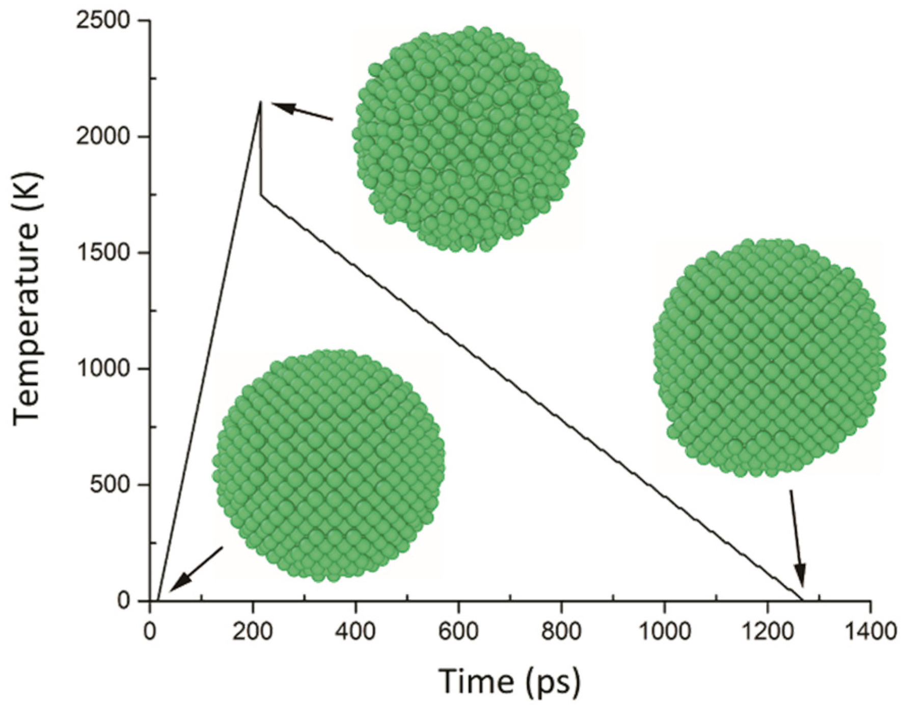
3. Results and Discussion

3.1. First-Principle Calculations

As the adsorbate in this study, geometrical optimization and energetical minimization of ether molecule play an elemental role for the following DFT and MD simulations. Figure 3 presents the chemical structure of ether molecule, in which all atoms of ether molecule have been labelled, respectively, to associate each atom with its charge value. According to the DFT population analysis result, the charge of each atom is listed in Table 1. Later, those parameters will be set as initial datafile for MD simulations. Next, an optimized ether molecule is placed above the Fe (110) surface to obtain the optimal adsorption site. As mentioned above, there are four potential sites applied to calculate the adsorption energy, and the initial distance between O1 atom and the first layer of Fe (110) is about 3.0 Å. Taking the long bridge site as an example, the adsorbed configuration is presented as Figure 4. Through DFT calculation, the adsorption energy for each site is summarized in Table 2. As shown in the table, all those four computed adsorption energies are negative values meaning that this is an exothermic adsorption process. Thus, it could be deduced that more energy will be released if the adsorption is stronger. According to their comparisons, it appears that the long bridge adsorption site on Fe (110) is an optimal site for the adsorption of ether molecule. In other words, the obtained configuration will be more stable than other configurations if an ether molecule is adsorbed on long bridge site. Finally, details of original and adsorbed ether molecules’ chemical bonds are summarised in Table 3.

3.2. Single Sphere Coating Model

To uncover the mechanism of coating Fe nanoparticles by liquid ether, a single sphere model has been placed to be surrounded by the ether molecules. Although the model was performed for totally 1 ns, it is observed that the coating behavior mainly occurred in the first 30 ps. Figure 5 exhibits four snapshots of adsorption configurations with intervals of 8 ps. Those snapshots are cross-sections of the single sphere model and each is about 25 Å thick. Initially (0 ps), the Fe nanoparticle and bulk of ether molecules were separated by a vacuum about 15 Å long. After 8 ps, several ether molecules were moved into the vacuum and captured on Fe surface. During this period of time, the density of bulk region was still higher than vacuum. In the next two intervals, the distribution of ether molecules tended to be uniform. While, in this process, most parts of Fe surface were coated successfully. However, the coating effect was not isotropy, especially because the bottom right corner of Fe particle was explicitly coated less than other parts. Therefore, it could be summarized that the coating behavior on this occasion did not occur simultaneously in 360°, but spread step by step until the distribution was stabilized. The stability of adsorption system was not convincing enough to be judged visually. Therefore, a statistic of potential energy within 200 ps is plotted, as shown in Figure 6. The figure illustrates that the potential energy of system decreased drastically during the early stage of adsorption, then stabilized from 45 ps. Also after 150 ps, the system was reasonable to be considered as an equilibrated system.
Despite the plot of potential energy, the adsorption curve can also be used as a tool to analyze the adsorption process in detail. As Figure 7 displays, the adsorption of ether molecules could be basically divided into three stages. Stage 1 refers to the first 30 ps, in which ether molecules were adsorbed effectively and the curve sharply climbed up to the quantity of 280 molecules. Then, from 30 to 45 ps, the rate of adsorption slowed down, and the curve became smoother. Finally, the stabilized adsorption curve remains fluctuating around the quantity of 340 molecules. Figure 8 depicts the charge distribution of Fe nanoparticle at 1 ns when all ether molecules have been removed. Similarly, ¼ of particle have been sliced with the aim to present the internal distribution. It confirms that the adsorption process was typically a charge transfer process as well. Charge values of Fe atoms were almost zero initially, and then negative charges moved from Fe to ether atoms with the occurrence of adsorption. Therefore, the transfer and attraction effect between Fe atoms and ether molecules generally motivated adsorption behaviors.
Besides, such a strong attraction effect from plenty of ether molecules with high kinetic energy will inevitably cause radial pressure on Fe nanoparticle. Figure 9 is the analysis of Fe displacement at 200 ps. According to this figure, it is observed that pressure from the bulk of ether made Fe atoms left their original coordinates. Typically, color coded configuration shows that shell atoms were explicitly affected larger than core atoms. Also, there was little displacement within the radius of 18 Å. The closer the Fe atoms were to shell surface, the higher the extent of displacement would be. When the maximum displacement reached for about 6.36 Å, the radius of particle would be enlarged until 25.66 Å. Besides, Figure 10 displaces the dynamic distribution of shell atoms’ displacement. From 0 to 200 ps, those displacement behaviors were mainly happened before 45 ps. The most important aspect is that this result is in line with the adsorption cure (Figure 7). As such, the adsorption of ether molecules is confirmed to effectively cause displacements of shell Fe atoms.
Until then, the preparation of ether coated Fe nanoparticle is still unfinished, especially since the Fe nanoparticle is still soaked under liquid ether. The final step will be a filtering treatment in order to form a purely coated particle without other free molecules. Previously, we successfully filtered ether coated Al nanoparticles [16]. This time, the Fe nanoparticle system was treated with the same principle and method. Figure 11 presents the desorption process caused by filtering treatment. The figure demonstrates that the ether coated configuration has been stabilized at room temperature (300 K), because there was no desorbed ether molecule since cycle 8. Figure 11 also displays the obtained coating configuration with 259 ether molecules.

3.3. Double Sphere Coating Model

Although the single sphere model has been broadly applied to study dynamic or reaction behaviors of various metal nanoparticles previously [14,17,55], practical impacts from multiparticle environment is still inevitable. In this study, a double sphere model was built to further uncover coating mechanisms for multiparticle model. As mentioned previously, double Fe particles model have been pre-built, and the settlement of ether molecules was entirely same with single sphere model (Section 3.2). Figure 12 is the cross-section snapshot of double sphere model from 0 to 15 ps. Similar with the single sphere model, the coating behavior in this section was neither performed by uniform distribution. At about 4 ps, there were two vacuum spaces formed symmetrically between two nanoparticles. Then their volume shrank step by step and were finally filled up after 8 ps. According to the configuration at 15 ps, all parts of Fe shell have been coated entirely and the appearance of neighbor particles did not lead to exposure of particle surface.
As the evaluation of coating process, another adsorption curve is plotted as shown in Figure 13. In which, stage 1 refers to the rapid coating process happened from 0 to 15 ps, then the coating curve slowly trended to be stabilized until 40 ps. Generally, the time length of overall coating process was in line with the single sphere model. From 40 ps to 1 ns, there were totally about 638 ether molecules coated on Fe surface. The proportion of maximum adsorptions for double sphere model and single sphere model was about 1.876. Due to the consideration of overlapped area, this proportion means that the coating effect for those two models are similar with each other. Analyzed from the angle of potential energy, the equilibrium state of double sphere system is represented by Figure 14. To further investigate the impact of multiparticle environment, uncontacted and contacted regions of the left nanoparticle are labelled as regions A and B respectively as indicated in Figure 15. Then, each of their adsorption curves is plotted as well. It is observed that the adsorption behaviour of ether molecules for region B was typically affected. This is because parts of particle surface are covered by the other one, and then the availability of adsorption site is limited.
Figure 16 is the cross section of double sphere model at 1 ns. The figure is colored by the extent of the atoms’ movement in order to present their displacement distribution. It could be obviously observed that a layer of ether molecules with relatively low displacement was coated around the shell of Fe nanoparticles. In other words, those molecules were proved to be captured by the adsorption effects. In contrast with the single sphere model, the gap between two particles was under the double adsorption influence. Dynamic properties of ether molecules in this region ought to be different from other free molecules, although they were not entirely adsorbed. Simultaneously affected by both of those nanoparticles, the region between two nanoparticles were more likely to be with low displacement and the trajectory of their movement was restricted in this situation. Kinetic energy is another property to evaluate the double adsorption influence. This is because the value of kinetic energy is directly determined by the velocity of each atom. Just as in Figure 16, the distribution of kinetic energy at the same moment is presented in Figure 17. In this figure, the double adsorption influence is presented more clearly than in Figure 16, because the low kinetic energy area between two nanoparticles is explicitly thicker than other parts of configuration.

4. Conclusions

Based on first-principle calculations and MD simulations, the mechanism of coating ether on Fe nanoparticles has been discussed in this study. Above all, the obtained DFT results show that this coating behavior was generally an exothermic process, because the energy of adsorbed system was reduced comparing with the separated components. Among four computed adsorption sites, the long bridge site was confirmed to be the most stable site for ether adsorption. According to MD simulations of the single sphere model, the general coating process was found to be non-uniform, as some parts of the adsorption surface were coated more rapidly than other parts. However, all surfaces were stably coated in the end. The equilibrium state is validated by plots of both the potential energy and adsorption curve. It is also demonstrated that the outer shell of Fe atoms was affected significantly by the coating effects, exhibiting changes such as atomic charge transfer and displacement. Finally, the purely coated configuration was successfully obtained. Furthermore, the double sphere model showed that the gap between two particles was coated later than other parts of particles. Besides, the number of coated ether molecules reduced as well. Meanwhile, the movement of uncoated ether molecules in this gap was hindered because of the double adsorption effects of two neighboring particles.

Author Contributions

Conceptualization, R.S.; Validation, M.W.; Data Curation, S.H. and P.L.; Writing—Original Draft Preparation, J.S.; Supervision, M.W.

Funding

This research was funded by the Fundamental Research Funds for Central Universities (HEUCFG201815).

Conflicts of Interest

The authors declare that they have no conflict of interest.

References

  1. Kabir, E.; Kumar, V.; Kim, K.H.; Yip, A.C.; Sohn, J.R. Environmental impacts of nanomaterials. J. Environ. Manag. 2018, 225, 261–271. [Google Scholar] [CrossRef] [PubMed]
  2. Sun, Y.P.; Li, X.Q.; Cao, J.; Zhang, W.X.; Wang, H.P. Characterization of zero-valent iron nanoparticles. Adv. Colloid Interface Sci. 2006, 120, 47–56. [Google Scholar] [CrossRef] [PubMed]
  3. Wang, C.B.; Zhang, W.X. Synthesizing nanoscale iron particles for rapid and complete dechlorination of TCE and PCBs. Environ. Sci. Technol. 1997, 31, 2154–5156. [Google Scholar] [CrossRef]
  4. Huber, D.L. Synthesis, properties, and applications of iron nanoparticles. Small 2005, 1, 482–501. [Google Scholar] [CrossRef] [PubMed]
  5. Newsome, L.; Morris, K.; Cleary, A.; Masters-Waage, N.K.; Boothman, C.; Joshi, N.; Atherton, A.; Lloyd, J.R. The impact of iron nanoparticles on technetium-contaminated groundwater and sediment microbial communities. J. Hazard. Mater. 2019, 364, 134–142. [Google Scholar] [CrossRef] [PubMed]
  6. Yazdani, M.; Ebrahimi-Nik, M.; Heidari, A.; Abbaspour-Fard, M.H. Improvement of biogas production from slaughterhouse wastewater using biosynthesized iron nanoparticles from water treatment sludge. Renew. Energy 2019, 135, 496–501. [Google Scholar] [CrossRef]
  7. Eremin, A.; Gurentsov, E. Evaporation temperature depression with decrease of iron nanoparticle size. Validation of semi-empirical models. Mater. Chem. Phys. 2019, 228, 180–186. [Google Scholar] [CrossRef]
  8. Yadav, A.; Kumar, R.; Choudhary, H.K.; Sahoo, B. Graphene-oxide coating for corrosion protection of iron particles in saline water. Carbon 2018, 140, 477–487. [Google Scholar] [CrossRef]
  9. Leng, Y.; Sato, K.; Li, J.G.; Ishigaki, T.; Iijima, M.; Kamiya, H.; Yoshida, T. Iron nanoparticles dispersible in both ethanol and water for direct silica coating. Powder Technol. 2009, 196, 80–84. [Google Scholar] [CrossRef]
  10. Dulinska-Molak, I.; Chlanda, A.; Li, J.; Wang, X.; Bystrzejewski, M.; Kawazoe, N.; Chen, C.; Swieszkowski, W. The influence of carbon-encapsulated iron nanoparticles on elastic modulus of living human mesenchymal stem cells examined by atomic force microscopy. Micron 2018, 108, 41–48. [Google Scholar] [CrossRef]
  11. Khramtsov, P.; Kropaneva, M.; Byzov, I.Y.; Minin, A.; Mysik, A.; Timganova, V.; Bochkova, M.; Uimin, M.; Zamorina, S.; Yermakov, A.; et al. Conjugation of carbon coated-iron nanoparticles with biomolecules for NMR-based assay. Colloids Surf. B Biointerfaces 2019, 176, 256–264. [Google Scholar] [CrossRef] [PubMed]
  12. McGrath, A.J.; Dolan, C.; Cheong, S.; Herman, D.A.; Naysmith, B.; Zong, F.; Galvosas, P.; Farrand, K.J.; Hermans, I.F.; Brimble, M.; et al. Stability of polyelectrolyte-coated iron nanoparticles for T2-weighted magnetic resonance imaging. J. Magn. Magn. Mater. 2017, 439, 251–258. [Google Scholar] [CrossRef]
  13. Hong, S.; van Duin, A.C. Atomistic-scale analysis of carbon coating and its effect on the oxidation of aluminum nanoparticles by ReaxFF-molecular dynamics simulations. J. Phys. Chem. C 2016, 120, 9464–9474. [Google Scholar] [CrossRef]
  14. Yi, Q.; Xu, J.; Liu, Y.; Zhai, D.; Zhou, K.; Pan, D. Molecular dynamics study on core-shell structure stability of aluminum encapsulated by nano-carbon materials. Chem. Phys. Lett. 2017, 669, 192–195. [Google Scholar] [CrossRef]
  15. Kim, K.T.; Kim, D.W.; Kim, S.H.; Kim, C.K.; Choi, Y.J. Synthesis and improved explosion behaviors of aluminum powders coated with nano-sized nickel film. Appl. Surf. Sci. 2017, 415, 104–108. [Google Scholar] [CrossRef]
  16. Sun, R.; Liu, P.; Qi, H.; Liu, J.; Ding, T. Molecular dynamic simulations of ether-coated aluminum nano-particles as a novel hydrogen source. J. Nanopart. Res. 2019, 21, 72. [Google Scholar] [CrossRef]
  17. Liu, J.; Liu, P.; Wang, M. Molecular dynamics simulations of aluminum nanoparticles adsorbed by ethanol molecules using the ReaxFF reactive force field. Comput. Mater. Sci. 2018, 151, 95–105. [Google Scholar] [CrossRef]
  18. Zhang, Y.R.; van Duin, A.C.; Luo, K.H. Investigation of ethanol oxidation over aluminum nanoparticle using ReaxFF molecular dynamics simulation. Fuel 2018, 234, 94–100. [Google Scholar] [CrossRef]
  19. Pašti, I.A.; Gavrilov, N.M.; Mentus, S.V. Hydrogen adsorption on palladium and platinum overlayers: DFT study. Adv. Phys. Chem. 2011, 2011, 1–8. [Google Scholar] [CrossRef]
  20. Xie, W.; Peng, L.; Peng, D.; Gu, F.L.; Liu, J. Processes of H2 adsorption on Fe (110) surface: A density functional theory study. Appl. Surf. Sci. 2014, 296, 47–52. [Google Scholar] [CrossRef]
  21. Chiang, H.N.; Nachimuthu, S.; Cheng, Y.C.; Damayanti, N.P.; Jiang, J.C. A DFT study of ethanol adsorption and decomposition on α-Al2O3 (0001) surface. Appl. Surf. Sci. 2016, 363, 636–643. [Google Scholar] [CrossRef]
  22. Tan, X.; Zhou, J.; Peng, Y. First-principles study of oxygen adsorption on Fe (110) surface. Appl. Surf. Sci. 2012, 258, 8484–8491. [Google Scholar] [CrossRef]
  23. Ossowski, T.; Kiejna, A. Oxygen adsorption on Fe (110) surface revisited. Surf. Sci. 2015, 637, 35–41. [Google Scholar] [CrossRef]
  24. Fatti, G.; Restuccia, P.; Calandra, C.; Righi, M.C. Phosphorus adsorption on Fe (110): An ab initio comparative study of iron passivation by different adsorbates. J. Phys. Chem. C 2018, 122, 28105–28112. [Google Scholar] [CrossRef]
  25. Grimme, S.; Antony, J.; Ehrlich, S.; Krieg, H. A consistent and accurate ab initio parametrization of density functional dispersion correction (DFT-D) for the 94 elements H–Pu. J. Chem. Phys. 2010, 132, 154104. [Google Scholar] [CrossRef]
  26. Tamijani, A.A.; Salam, A.; de Lara-Castells, M.P. Adsorption of noble-gas atoms on the TiO2 (110) surface: An ab initio-assisted study with van der Waals-corrected DFT. J. Phys. Chem. C 2016, 120, 18126–18139. [Google Scholar] [CrossRef]
  27. Thonhauser, T.; Cooper, V.R.; Li, S.; Puzder, A.; Hyldgaard, P.; Langreth, D.C. Van der Waals density functional: Self-consistent potential and the nature of the van der Waals bond. Phys. Rev. B 2007, 76, 125112. [Google Scholar] [CrossRef] [Green Version]
  28. Hollingsworth, S.A.; Dror, R.O. Molecular dynamics simulation for all. Neuron 2018, 99, 1129–1143. [Google Scholar] [CrossRef]
  29. Karplus, M.; McCammon, J.A. Molecular dynamics simulations of biomolecules. Nat. Struct. Biol. 2002, 9, 646–652. [Google Scholar] [CrossRef]
  30. Hemeda, A.A.; Esteves, R.J.A.; McLeskey Jr, J.T.; Gad-el-Hak, M.; Khraisheh, M.; Tafreshi, H.V. Molecular dynamic simulations of fibrous distillation membranes. Int. Commun. Heat Mass Transf. 2018, 98, 304–309. [Google Scholar] [CrossRef]
  31. Plimpton, S. Fast parallel algorithms for short-range molecular dynamics. J. Comput. Phys. 1995, 117, 1–19. [Google Scholar] [CrossRef]
  32. Bou-Rabee, N. Time integrators for molecular dynamics. Entropy 2013, 16, 138–162. [Google Scholar] [CrossRef]
  33. in’t Veld, P.J.; Plimpton, S.J.; Grest, G.S. Accurate and efficient methods for modeling colloidal mixtures in an explicit solvent using molecular dynamics. Comput. Phys. Commun. 2008, 179, 320–329. [Google Scholar] [CrossRef]
  34. Tersoff, J. New empirical model for the structural properties of silicon. Phys. Rev. Lett. 1986, 56, 632–635. [Google Scholar] [CrossRef] [PubMed]
  35. Liu, J.; Guo, X. ReaxFF molecular dynamics simulation of pyrolysis and combustion of pyridine. Fuel Process. Technol. 2017, 161, 107–115. [Google Scholar] [CrossRef]
  36. Mortier, W.J.; Ghosh, S.K.; Shankar, S. Electronegativity-equalization method for the calculation of atomic charges in molecules. J. Am. Chem. Soc. 1986, 108, 4315–4320. [Google Scholar] [CrossRef]
  37. Nayebi, P.; Zaminpayma, E. A molecular dynamic simulation study of mechanical properties of graphene–polythiophene composite with Reax force field. Phys. Lett. A 2016, 380, 628–633. [Google Scholar] [CrossRef]
  38. Aryanpour, M.; Van Duin, A.C.; Kubicki, J.D. Development of a reactive force field for iron-oxyhydroxide systems. J. Phys. Chem. A 2010, 114, 6298–6307. [Google Scholar] [CrossRef]
  39. Russo Jr, M.F.; Li, R.; Mench, M.; Van Duin, A.C. Molecular dynamic simulation of aluminum-water reactions using the ReaxFF reactive force field. Int. J. Hydrogen Energy 2011, 36, 5828–5835. [Google Scholar] [CrossRef]
  40. Hong, S.; Van Duin, A.C. Molecular dynamics simulations of the oxidation of aluminum nanoparticles using the ReaxFF reactive force field. J. Phys. Chem. C 2015, 119, 17876–17886. [Google Scholar] [CrossRef]
  41. Liu, P.; Liu, J.; Wang, M. Ignition and combustion of nano-sized aluminum particles: A reactive molecular dynamics study. Combust. Flame 2019, 201, 276–289. [Google Scholar] [CrossRef]
  42. Duy, T.P.; Van Hoang, V. Atomic mechanism of homogeneous melting of bcc Fe at the limit of superheating. Phys. B 2012, 407, 978–984. [Google Scholar] [CrossRef]
  43. Martínez, L.; Andrade, R.; Birgin, E.G.; Martínez, J.M. Packmol: A package for building initial configurations for molecular dynamics simulations. J. Comput. Chem. 2009, 30, 2157–2164. [Google Scholar] [CrossRef] [PubMed]
  44. Humphrey, W.; Dalke, A.; Schulten, K. VMD: Visual Molecular Dynamics. J. Mol. Graph. 1996, 14, 33–38. [Google Scholar] [CrossRef]
  45. Nosé, S. A unified formulation of the constant temperature molecular dynamics methods. J. Chem. Phys. 1984, 81, 511–519. [Google Scholar] [CrossRef] [Green Version]
  46. Hoover, W.G. Canonical dynamics: Equilibrium phase-space distributions. Phys. Rev. A. 1985, 31, 1695–1697. [Google Scholar] [CrossRef] [Green Version]
  47. Berendsen, H.J.; Postma, J.V.; van Gunsteren, W.F.; DiNola, A.R.H.J.; Haak, J.R. Molecular-dynamics with coupling to an external bath. J. Chem. Phys. 1984, 81, 3684–3690. [Google Scholar] [CrossRef]
  48. Andersen, H.C. Molecular dynamics simulations at constant pressure and/or temperature. J. Chem. Phys. 1980, 2384, 2384–2393. [Google Scholar] [CrossRef]
  49. Stukowski, A. Visualization and analysis of atomistic simulation data with OVITO—The open visualization tool. Model. Simul. Mater. Sci. Eng. 2010, 18, 015012. [Google Scholar] [CrossRef]
  50. Milman, V.; Refson, K.; Clark, S.J.; Pickard, C.J.; Yates, J.R.; Gao, S.P.; Hasnip, P.J.; Probert, M.I.J.; Perlov, A.; Segall, M.D. Electron and vibrational spectroscopies using DFT, plane waves and pseudopotentials: CASTEP implementation. J. Mol. Struct. THEOCHEM 2010, 954, 22–35. [Google Scholar] [CrossRef]
  51. Giannozzi, P.; Baroni, S.; Bonini, N.; Calandra, M.; Car, R.; Cavazzoni, C.; Ceresoli, D.; Chiarotti, G.L.; Cococcioni, M.; Dabo, I.; et al. QUANTUM ESPRESSO: A modular and opensource software project for quantum simulations of materials. J. Phys. Condens. Matter 2009, 21, 395502. [Google Scholar] [CrossRef] [PubMed]
  52. Giannozzi, P.; Andreussi, O.; Brumme, T.; Bunau, O.; Nardelli, M.B.; Calandra, M.; Car, R.; Cavazzoni, C.; Ceresoli, D.; Cococcioni, M.; et al. Advanced capabilities for materials modelling with Quantum ESPRESSO. J. Phys. Condens. Matter 2017, 29, 465901. [Google Scholar] [CrossRef] [PubMed] [Green Version]
  53. Momma, K.; Izumi, F. VESTA 3 for three-dimensional visualization of crystal, volumetric and morphology data. J. Appl. Crystallogr. 2011, 44, 1272–1276. [Google Scholar] [CrossRef]
  54. Perdew, J.P.; Burke, K.; Ernzerhof, M. Generalized gradient approximation made simple. Phys. Rev. Lett. 1996, 77, 3865–3868. [Google Scholar] [CrossRef] [PubMed]
  55. Henz, B.J.; Hawa, T.; Zachariah, M. Molecular dynamics simulation of the energetic reaction between Ni and Al nanoparticles. J. Appl. Phys. 2009, 105, 124310. [Google Scholar] [CrossRef] [Green Version]
Figure 1. Plot of temperature changes for annealing Fe nanoparticle.
Coatings 09 00395 g001
Figure 2. Top view of Fe (110) supercell and four different adsorption sites.
Coatings 09 00395 g002
Figure 3. The chemical configuration of ether molecule with its labelled atoms.
Coatings 09 00395 g003
Figure 4. Snapshot of an ether molecule adsorbed on a long bridge site of Fe (110) supercell.
Coatings 09 00395 g004
Figure 5. Snapshots of single sphere model at (a) 0 ps, (b) 8 ps, (c) 16 ps and (d) 24 ps.
Coatings 09 00395 g005
Figure 6. Decrease of potential energy as a function of time for single sphere model.
Coatings 09 00395 g006
Figure 7. The number of ether molecules adsorbed on single sphere model.
Coatings 09 00395 g007
Figure 8. Snapshot of Fe nanoparticle colored by multiple of electron charge at 1 ns.
Coatings 09 00395 g008
Figure 9. Radial displacement distribution of Fe nanoparticle at 200 ps.
Coatings 09 00395 g009
Figure 10. Plot of maximum displacements of Fe nanoparticle as a function of time.
Coatings 09 00395 g010
Figure 11. The quantity of desorbed ether molecules in 10 filtering cycles and the final configuration.
Coatings 09 00395 g011
Figure 12. Snapshots of double sphere model at (a) 0 ps, (b) 2 ps, (c) 4 ps, (d) 6 ps, (e) 8 ps, and (f) 15 ps.
Coatings 09 00395 g012
Figure 13. The number of ether molecules adsorbed on double sphere model.
Coatings 09 00395 g013
Figure 14. Decrease of potential energy as a function of time for double sphere model.
Coatings 09 00395 g014
Figure 15. Adsorption curves and snapshot of different regions of double sphere model.
Coatings 09 00395 g015
Figure 16. Displacement distribution of sliced double sphere model (unit: Å).
Coatings 09 00395 g016
Figure 17. Kinetic energy distribution of sliced double sphere model (unit: kcal/mole).
Coatings 09 00395 g017
Table 1. The charge information of atoms in ether.
AtomsCharge (Multiple of Charge)
H10.2024
H20.2029
H30.2029
H40.162
H50.162
C1−0.454
C2−0.0303
O10.3535
Table 2. Adsorption energies of each adsorption site.
Adsorption SitesAdsorption Energy (kcal/mol)
atop−20.339
hcp−19.500
long bridge−24.307
short bridge−20.453
Table 3. Values of bond length (Å) and angle (°) for each state of ether molecule.
Adsorption SitesC–CC–OC–H˂C–O–C˂O–C–H˂H10–O4–H9
Original1.5131.4271.109112.742109.755108.272
atop1.4971.441.107108.843108.938107.123
hcp1.4981.4371.106109.887109.056105.424
long bridge1.51.4341.106110.962109.656106.749
short bridge1.51.4351.103110.424109.087105.562

