Article

Hybrid Nanostructured Antireflection Coating by Self-Assembled Nanosphere Lithography

1
Key Laboratory of Optical System Advanced Manufacturing Technology, Changchun Institute of Optics, Fine Mechanics and Physics, Chinese Academy of Sciences, Changchun 130033, China
2
Research Center of Laser Fusion, China Academy of Engineering Physics, Mianyang 621900, China
*
Authors to whom correspondence should be addressed.
Coatings 2019, 9(7), 453; https://doi.org/10.3390/coatings9070453
Submission received: 14 June 2019 / Revised: 15 July 2019 / Accepted: 18 July 2019 / Published: 18 July 2019

Abstract

:
Broadband antireflection (AR) coatings are essential elements for improving the photocurrent generation of photovoltaic modules or the enhancement of visibility in optical devices. In this paper, we report a hybrid nanostructured antireflection coating combination that is a clean and efficient method for fabricating a nanostructured antireflection coating (ARC). A multilayer thin-film was introduced between the ARC and substrate to solve the significant problem of preparing nanostructured ARCs on different substrates. In this way, we rebuilt a gradient refractive index structure and optimize the antireflective property by simply adjusting the moth-eye structure and multilayers. Subwavelength-structured cone arrays were directly patterned using a self-assembled single-layer polystyrene (PS) nanosphere array as an etching mask. Nanostructure coatings exhibited excellent broadband and wide-angle antireflective properties. The bottom-up preparation process and hybrid structural combination have the potential to significantly enhance the broadband and wide-angle antireflective properties for a number of optical systems that require high transparency, which is promising for reducing the manufacturing cost of nanostructured AR coatings.

1. Introduction

Antireflection coatings have been a research hotspot for a long time because they play an essential role in antiglare monitors [1], car dashboards [2], solar cells [3,4,5,6], and most optical systems. Generally, depositing a multilayer coating onto the substrates could reduce the surface reflection to near zero over a broad wavelength by precisely controlling the refractive index and the thickness of each film layer [7]. However, it is not only very difficult to find coating materials with the appropriate refractive index and excellent transparency for each layer, but also hard to control the film thickness. In addition, a wider spectrum and larger angle demand will increase the quantity of thin-film layers, which means that it needs a longer deposition time, which introduces more error. Thus, a coating method with an adjustable and low-cost process is still an urgent problem for broadband and wide-angle antireflection coatings.
Recently, researchers have found that a bio-inspired moth-eye nanostructure exhibits outstanding broadband low reflectivity and high transmission with wide-angle incident light compared to conventional antireflective multilayer coatings [8,9,10,11,12,13,14,15,16]. This kind of bio-inspired nanostructure is considered an effective way to enhance the photoconversion efficiency of solar cells [17,18,19,20] or the visibility of displays [21,22,23]. To fabricate it, a top-down approach, such as e-beam [24,25], focused ion beam etching [26,27], or X-ray lithography [28,29,30], is primarily used. However, such advanced nanofabrication methods are limited in large-area applications since they take a longer time and are costlier. Although numerous investigations have been carried out to realize an antireflective surface on glass substrates [31,32], a low-cost method to fabricate an antireflection coating (ARC) with large-area uniformity and easy tuning of the antireflective property is still strongly in need. In order to achieve wide-angle anti-reflection properties, the use of nanostructures is an inevitable trend. In this paper, we introduce an inexpensive method to synthesize a moth-eye SiO2 ARC by using reacting ion-beam etching (RIE) with a single-layer polystyrene (PS) nanosphere as a mask. We can optimize the antireflective properties of the moth-eye structure through carefully adjusting the self-assembly PS mask, which can be easily achieved by changing the size of the PS nanosphere [33,34]. Unlike the reported paper [35,36], the antireflection band we were concerned with was the much broader 400–2000 nm, which means a higher manufacturing difficulty. Besides, although there are some similarities in the process of preparing periodic nanostructured surfaces, single nanostructured surfaces are fundamentally different from the hybrid structures of the nanocone and multilayer versions we have studied. The applicability and antireflection ability of the hybrid structure are far stronger than the simple nanostructure anti-reflection film studied in most of the current papers [37,38]. This is not only reflected in the diversity of the structure, but the optimal multilayer film matching results can also be obtained via simulation optimization calculations to achieve excellent antireflection characteristics under the premise of ensuring process stability.
For a glass substrate, the antireflective property of a moth-eye SiO2 ARC is sufficient. In contrast, for a substrate with a refractive index larger than glass, the antireflective property of a moth-eye SiO2 antireflective structure degrades significantly. The exhibited antireflective property is due to a gradient refractive index from air to the substrate. Only when the moth-eye SiO2 antireflective structure exists, there is a dramatic improvement of the refractive index, which certainly breaks the gradient refractive index structure and weakens the antireflection effect, as seen in Figure 1a. In addition, the nanostructured etching material SiO2 is usually realized through a coating deposition process. When introducing the multilayer film, we only replaced the procedure of preparing the etching single-layer film by preparing the multilayer film, and experimental steps were not added during the whole experiment. Multilayer film deposition is also relatively inexpensive. The overall experimental procedure for the hybrid structure is suitable for the preparation of large-sized samples.
To solve this significant problem, we developed a hybrid structure combining the nanocone array and multilayer optical coating to achieve the antireflective property. In this way, we can rebuild a gradient refractive index structure and optimize the antireflective property by simply adjusting the moth-eye structure and multiple layers, as shown in Figure 1b.

2. Materials and Methods

At the beginning of our experiments, we utilized the 3D finite-difference time-domain (FDTD) method to theoretically calculate optimized structural parameters for a periodical nanocone, which included height, separation distance, and diameter. The FDTD simulation was performed using commercial software (Lumerical FDTD Solutions, version 8.15.736) to investigate the optical properties of the proposed hybrid structure, where the periodic boundary conditions were adopted for a unit cell in both X- and Y-directions and perfectly matched layers (PML) were applied in the Z-direction. The permittivity of SiO2 and Ta2O5 used in simulation were extracted from the data of Palik [39]. The incident source was a linearly polarized plane wave (400–2000 nm) propagating along the negative Z-direction with the E-field polarization to X-direction.
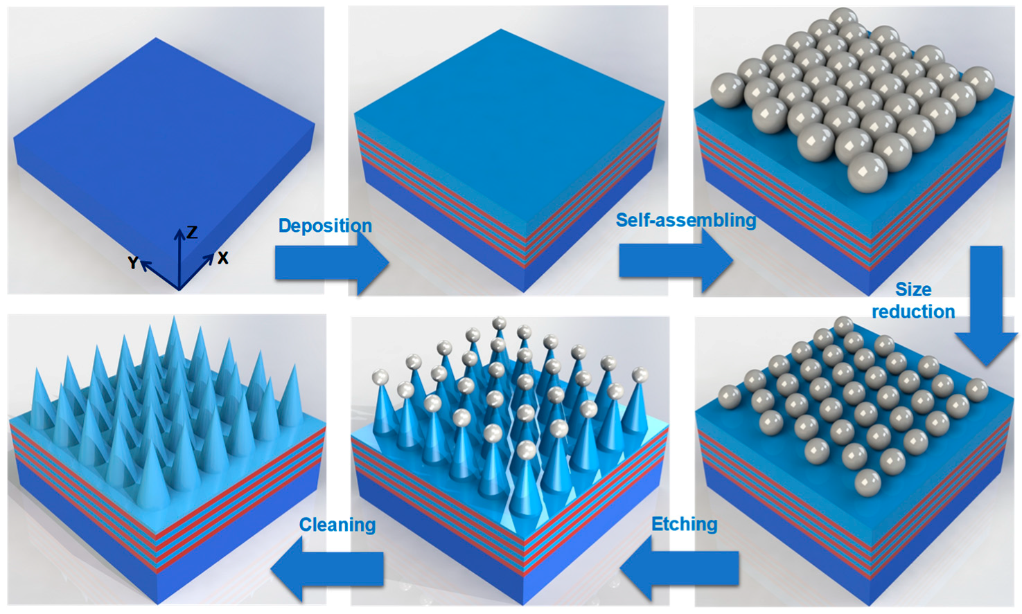
The schematic illustration of the procedures for making wafer-scale silica cone arrays is shown in Figure 2. All of the chemicals used were of reagent grade or better. The PS (500 nm in diameter) suspensions (5 wt.% in water) were bought from Huge Biotechnology Company (Shanghai, China). The fused silica and sapphire were used as substrates. First, they were cleaned in acetone, ethanol, and distilled water for 30 min in each solution. Then, an eight-layer coating of Ta2O5 and SiO2 was coated on sapphire using an ion-beam-assisted electron-beam evaporation deposition method through controlling the reflected optical value. The thickness of each layer was estimated based on the data provided by the crystal oscillate system of the evaporation coater (OPTRUN OTFC-1300, Shanghai, China). The outer layer was 600-nm thick SiO2 as the nanocone etching material. Second, the suspension of monodisperse PS and ethanol at a volume ratio of 1 to 1.2 was mixed. A glass slide (100 mm × 25 mm) used as a slope was cleaned in turn with acetone, ethanol, 98% H2SO4/H2O2 (3:1), and distilled water. After the glass slide was dried, it was placed obliquely onto an evaporation pan full of deionized water. About 140 mL of the mixed suspensions after the ultrasonic treatment was pipetted onto the oblique glass slide and slowly dipped into the water. A large-area colloidal monolayer was formed using the gas–liquid–solid interface self-assembly method. Third, the as-formed PS monolayer naturally subsided onto the chosen substrate when emptying all water from the bottom of the evaporation pan. The PS masks were dried in the super clean bench. In order to obtain the non-close-packed 2D colloidal crystals, the size of the PS nanospheres was reduced by oxygen plasma using the reactive ion etching (RIE) method in a controlled manner, with a 250 W power, 30 mTorr pressure, and 10 sccm O2 flow rate. In this way, the gap distance between neighboring nanoparticles was necessary to get the sites for the reaction between the SiO2 surface and plasma species. In this experiment, the gap distance was obtained with a 20% size reduction of the nanoparticles in ambient O2 plasma had occurred. Afterwards, an isotropic etching was carried out in a mixture of CF4 and O2 gases with ratio of 12.5:1 with a 150 W radio frequency power. Finally, we removed the PS nanospheres using oxygen plasma etching and ultrasonic cleaning in toluene solution for 10 min, leading to the formation of a pure SiO2 nanocone array.
In this fabrication process, the period can be adjusted using the size of the PS nanospheres and the diameter of the nanocone array can be controlled using different etching times for the RIE procedure. Furthermore, we evaluated the inner structure, surface reflectance, and surface morphology using a scanning electron microscope (SEM, JSM-6510 of JEOL, Tokyo, Japan), a spectrophotometer (Lambda 1100 of PerkinElmer, Waltham, MA, USA), and an atomic force microscope (AFM, EDG of Bruker, Billerica, MA, USA), respectively.

3. Results and Discussion

To evaluate the antireflection performance of nanocone arrays in the hybrid nanostructure, we calculated the average surface reflectance for 400–2000 nm wavelengths. The simulation results are shown in Figure 3. Figure 3a–c are the 3D image, cross-sectional, top-view diagrams, respectively. From Figure 3b, the main factors that influenced the surface reflectance of the nanocones were height H, separation distance D, and the diameter d of the underside. Because the etching masks were self-assembled PS nanospheres, the prepared nanocones were triangular packed, the same as the nanospheres packing pattern, as shown in Figure 3c. By adjusting a single factor of H, D, or d and keeping the other two constant, we obtained three diagrams, as shown in Figure 3d–f. For better antireflective properties from 400 to 2000 nm, a larger H, appropriate D, and larger d are preferred. The main purpose of the theoretical simulation calculations was to find the best nanocone array structural parameters with the lowest reflectivity under the premise of ensuring experimental stability and repeatability.
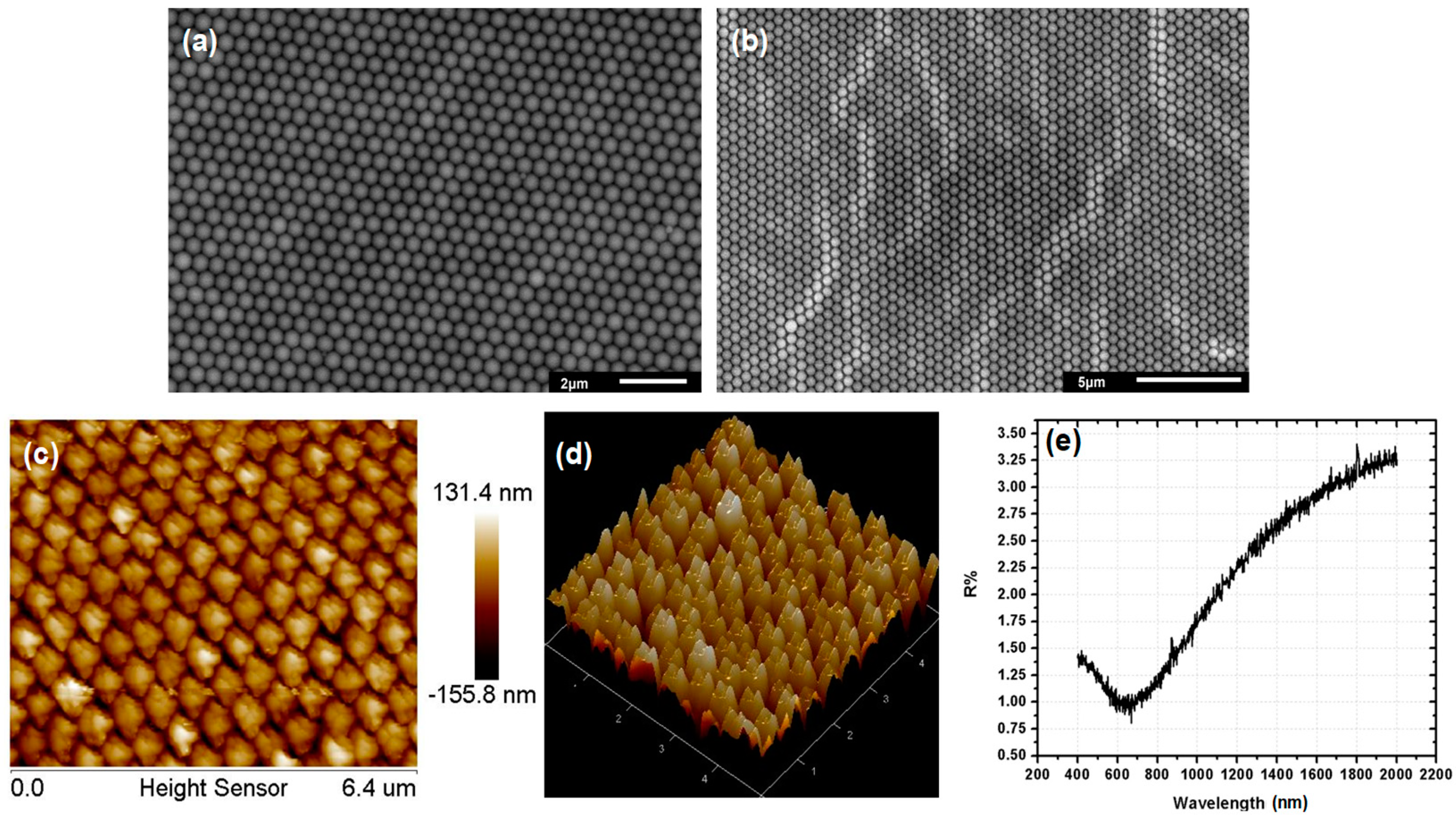
At the beginning of our experimental investigation process, a self-assembling PS-nanospheres etching mask and SiO2 nanocone array were carried out on the quartz substrate for the best antireflective nanostructure preparation process. Figure 4a,b shows the PS-nanospheres self-assembling single-layer mask using 7000× and 4000× magnified photographs. From these two pictures, it can be seen that the PS-nanospheres were packed tightly and there was almost no obvious defect in the single-layer etching mask. Just by using this self-assembly technology, a large-area and well-packed PS-nanosphere array was formed, which guaranteed the preparation of large-size antireflective nanostructures. Figure 4c,d shows the nanocone array surface morphology photos taken using AFM after direct etching. The nanocone array was well-packed, just as with the nanospheres mask, but the shape of each nanocone was unsatisfactory and they exhibited a multi-peak distribution. Furthermore, the disappointing nanocone array directly led to a disabled antireflective property, as shown in Figure 4e. The mean surface reflectance from 400 to 2000 nm was 2.3%. The irregular nanostructure array surface also had extra scattering and light loss. In this experiment, the size-reduction procedure was not introduced. Figure 4 provides additional proof that the size-reduction treatment was needed because at the beginning of the etching experiment, tightly packing the nanospheres did not offer enough etching space for the SiO2 coating and etching plasma.
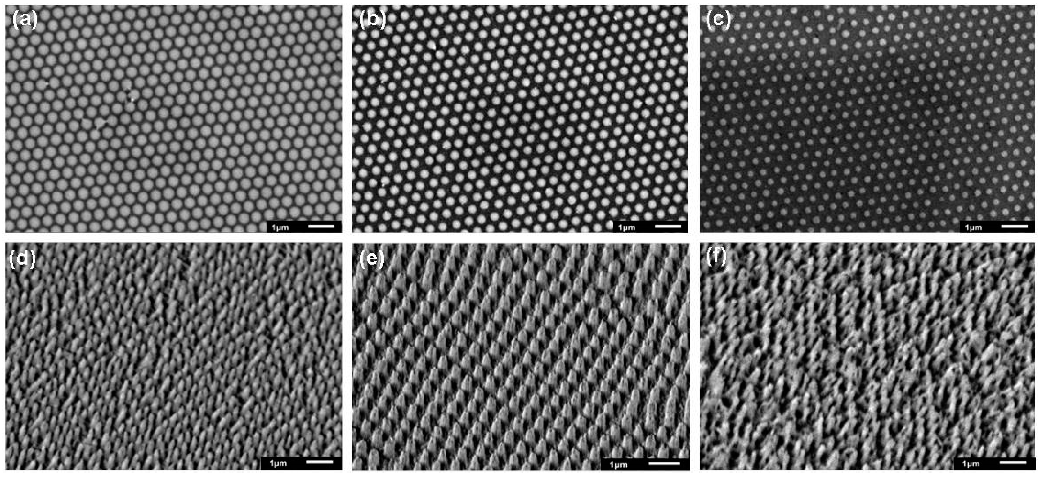
Figure 5a–c shows that the size of the self-assembled nanospheres mask was reduced using O2 plasma etching for 5, 10, and 15 s, respectively. The diameter of the 500-nm nanospheres shrank to 400, 270, and 130 nm, respectively. By using these three size-reduced etching masks, the new nanocone arrays after the etching process are shown in Figure 5d–f, respectively. The nanocone array in Figure 5d was still packed badly with a multi-peak shape, while Figure 5f exhibited a disorganized arrangement. In conclusion, introducing a 10 s O2-plasma size-reduction procedure is preferred since the resulting prepared nanocone array was well-packed and had a good smooth conical nanostructure.
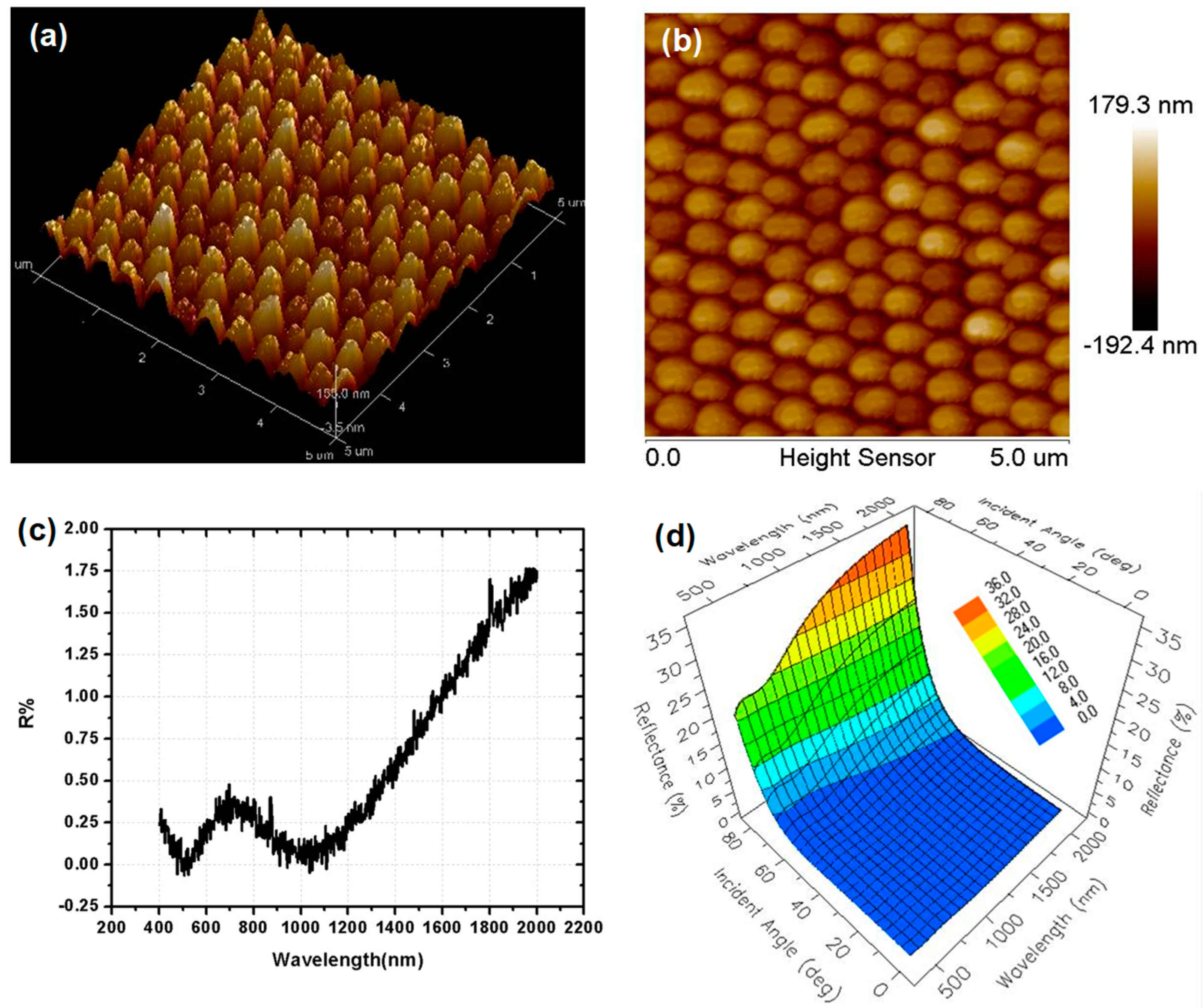
By utilizing the AFM method to visualize the nanocone array seen in Figure 5e, we obtained its 3D and 2D surface morphological images, as shown in Figure 6a,b. It showed that the multipeak shape was improved and the nanocone array also presented a good triangular packing mode. Its surface reflectance at different wavelengths and incident angles is shown in Figure 6c,d. In the measured spectral range, due to the graded refractive index profile of the SiO2 nanocone array, the average reflectance was significantly suppressed to 0.85%, while the reflectance was below 5% throughout the whole incident angle range from 0° to 65°.
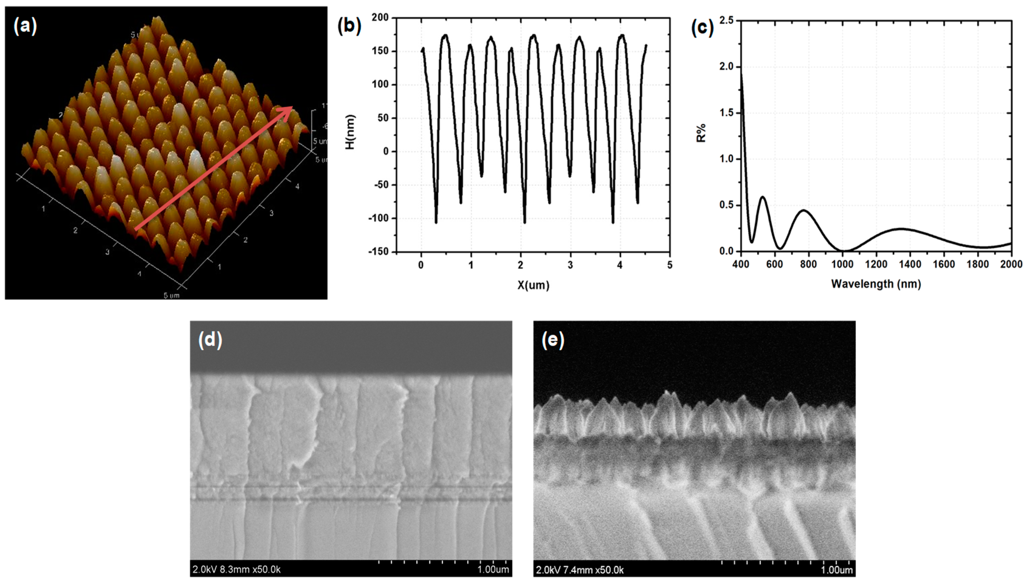
Based on the above experiments and results, the nanocone array of the hybrid AR nanostructure has been confirmed as successful. The multilayer coating between the high refractive index substrate and surface nanocone array should be optimized by an appropriate method. By means of an AFM measurement, we got a higher resolution surface 3D image of the nanocone array, as shown in Figure 7a. By using line-scanning mode to detect the surface profile of the red arrow line in Figure 7a, we got the contour line found in Figure 7b. Our proposed hybrid AR nanostructures were nanoscale cones with subwavelength spacing and acted to suppress all but zeroth-order diffraction. When the lateral dimensions were sufficiently small, the structure can be modeled by splitting the nanocones into many thin horizontal slices with an effective refractive index, neff, calculated using Bruggeman’s effective medium approximation. The prepared nanocone array was strictly centrally symmetrical. Therefore, we could apply the symmetric two-dimensional Bruggeman equation for two-material mixtures [40], as seen in Figure 7b, which is expressed as:
F ( n eff n 1 n eff + n 1 ) + ( 1 F ) ( n eff n 0 n eff + n 0 ) = 0
where F is the areal fraction of the nanostructure material in each slice, n0 is the refractive index of air, and n1 is the refractive index of the nanostructure material SiO2. The surface reflectance and transmittance through the hybrid AR nanostructure can be calculated using the transfer matrix method. In this way, the design problem regarding a multilayer coating for hybrid AR nanostructures can be easily simplified to a thin-film design problem. In this paper, we divided the nanocone into 10 slices, and by using a thin-film optimizing method, the thickness of each intermediate layer was obtained. The reflectance calculation result for the nanostructures without a multilayer on a sapphire substrate is shown in Figure 7c. Dividing the periodic nanostructure into more slices in the horizontal direction meant that the calculated data was closer to the real situation. However, due to the size of the structure and the measurement accuracy of the AFM, when the number of slices reached to a certain value, the calculation results hardly changed. Figure 7d allowed us to approximate the prepared multilayer coating dimensions for the hybrid design before the etching process. Furthermore, the final hybrid AR nanostructure is shown in Figure 7e.
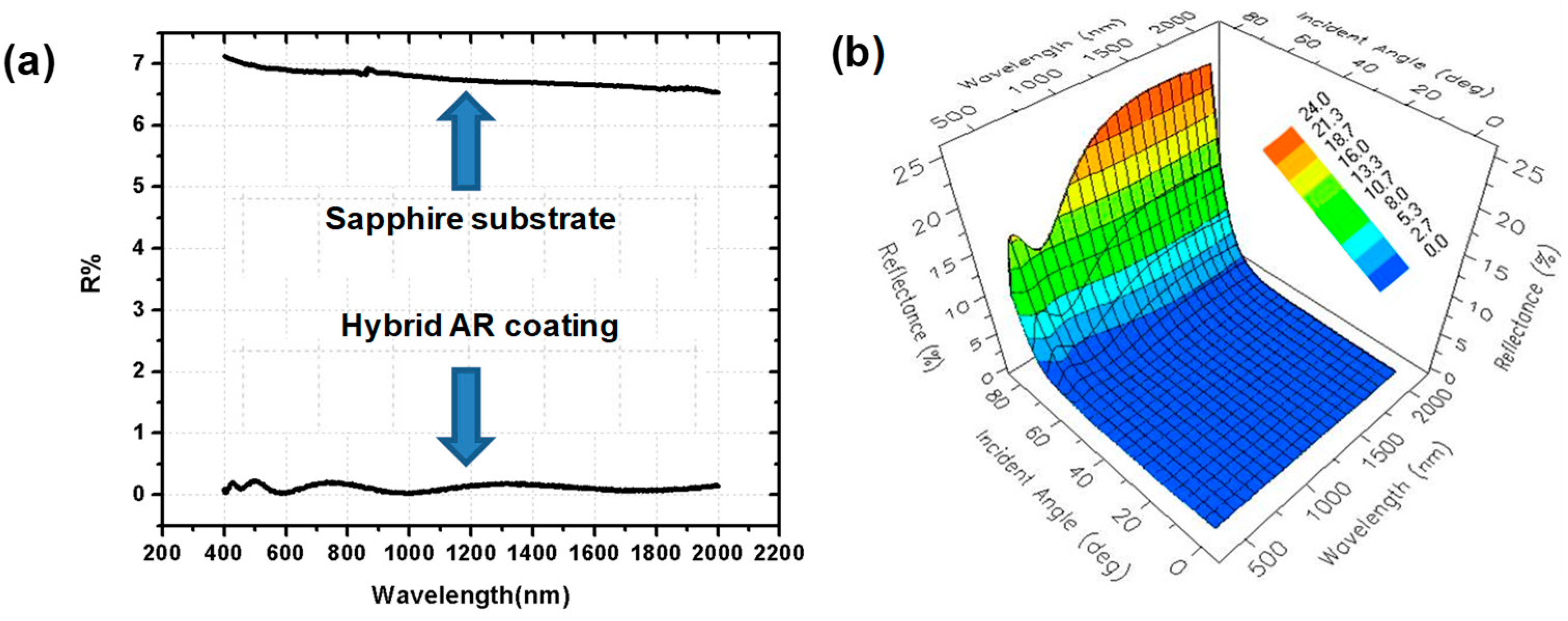
The reflectance of a hybrid AR nanostructure is shown in Figure 8a,b. The two curves in Figure 8a are the reflectance of sapphire substrate with and without a hybrid ARC. It can be concluded that the hybrid coating significantly suppressed the surface reflectance for a fairly broad spectrum. The average surface reflectance was as low as 0.65% for vertically incident light. Figure 8b displays the wide-angle antireflection property. With the incident angle increased to 65°, the surface reflectance could be controlled to less than 1%.

4. Conclusions

In summary, our results indicate that it is possible to significantly decrease the surface reflectance broadband and wide-angle incident light using a design that combines the antireflective nanocone array and a multilayer optical coating. This hybrid design had a 0.65% surface reflectance over 400–2000 nm light, and with the incident angle increased to 65°, surface reflectance could be controlled less than 1%. Subwavelength-structured cone arrays were directly patterned upon the substrate using a self-assembled single-layer PS-nanosphere array as an etching mask. Furthermore, normal-incidence specular reflection matched with the theoretical prediction from a rigorous coupled-wave analysis model. Overall, this bottom-up technique and hybrid structural combination strategy has the potential to markedly enhance the broadband and wide-angle properties for optical systems that require low reflection and high transparency.

Author Contributions

Conceptualization, Z.L. and Q.L.; Methodology, Z.L.; Software, Q.L., X.X., and C.S.; Validation, C.S., X.X., X.W., and J.G.; Formal Analysis, Z.L.; Investigations, Z.L.; Resources, Z.L. and H.Y.; Data Curation, X.X., C.S., and Q.L.; Writing—Original Draft Preparation, Z.L.; Writing—Review and Editing, Z.L., Q.L., and X.X.; Visualization, Z.L.; Supervision, Z.L.; Project Administration, Z.L.; Funding Acquisition, Z.L.

Funding

This research was funded by the National Natural Science Foundation of China (Nos. 61705226 and 61875193), Jilin Province Technical Research Project (No. 20190302082GX), and the Changchun Science and Technology Innovation “Shuangshi Project” Major Scientific and Technological Project (No. 19SS004).

Conflicts of Interest

The authors declare no conflict of interest.

References

  1. Macleod, H.A. Thin-Film Optical Filters, 4th ed.; CRC Press: Boca Raton, FL, USA, 2010. [Google Scholar]
  2. Walheim, S. Nanophase-separated polymer films as high-performance antireflection coatings. Science 1999, 283, 520–522. [Google Scholar] [CrossRef] [PubMed]
  3. Deng, C.; Ki, H. Pulsed laser deposition of refractive-index-graded broadband antireflection coatings for silicon solar cells. Sol. Energy Mater. Sol. Cells 2016, 147, 37–45. [Google Scholar] [CrossRef]
  4. Uzum, A.; Kuriyama, M.; Kanda, H.; Kimura, Y.; Tanimoto, K.; Ito, S. Non-vacuum processed polymer composite antireflection coating films for silicon solar cells. Energies 2016, 9, 633. [Google Scholar] [CrossRef]
  5. Makableh, Y.; Vasan, R.; Sarker, J.; Nusir, A.; Seal, S.; Manasreh, M.; Nusir, A. Enhancement of GaAs solar cell performance by using a ZnO sol–gel anti-reflection coating. Sol. Energy Mater. Sol. Cells 2014, 123, 178–182. [Google Scholar] [CrossRef]
  6. Cui, H.; Pillai, S.; Campbell, P.; Green, M. A novel silver nanoparticle assisted texture as broadband antireflection coating for solar cell applications. Sol. Energy Mater. Sol. Cells 2013, 109, 233–239. [Google Scholar] [CrossRef]
  7. Salman, K.A.; Omar, K.; Hassan, Z. Effective conversion efficiency enhancement of solar cell using ZnO/PS antireflection coating layers. Sol. Energy 2012, 86, 541–547. [Google Scholar] [CrossRef]
  8. Kosten, E.D.; Atwater, J.H.; Parsons, J.; Polman, A.; Atwater, H.A. Highly efficient GaAs solar cells by limiting light emission angle. Light. Sci. Appl. 2013, 2, e45. [Google Scholar] [CrossRef]
  9. Wang, B.; Price, J.S.; Giebink, N.C. Durable broadband ultralow index fluoropolymer antireflection coatings for plastic optics. Optica 2017, 4, 239. [Google Scholar] [CrossRef]
  10. Chang, Y.-J.; Chen, Y.-T. Broadband omnidirectional antireflection coatings for metal-backed solar cells optimized using simulated annealing algorithm incorporated with solar spectrum. Opt. Express 2011, 19, A875. [Google Scholar] [CrossRef]
  11. Victoria, M.; Domínguez, C.; Antón, I.; Sala, G. Antireflective coatings for multijunction solar cells under wide-angle ray bundles. Opt. Express 2012, 20, 8136. [Google Scholar] [CrossRef]
  12. Sarkar, S.; Pradhan, S.K. Silica-based antireflection coating by glancing angle deposition. Surf. Eng. 2019, 1, 1–4. [Google Scholar] [CrossRef]
  13. Ma, J.; Ai, Y.; Kang, L.; Liu, W.; Ma, Z.; Song, P.; Zhao, Y.; Yang, F.; Wang, X. A novel nano-cone cluster microstructure with anti-reflection and superhydrophobic properties for photovoltaic devices. Nano Res. Lett. 2018, 13, 332. [Google Scholar] [CrossRef] [PubMed]
  14. Pisco, M.; Galeotti, F.; Quero, G.; Grisci, G.; Micco, A.; Mercaldo, L.V.; Veneri, P.D.; Cutolo, A.; Cusano, A. Nano-sphere lithography for optical fiber tip nanoprobes. Light Sci. Appl. 2017, 6, e16229. [Google Scholar] [CrossRef] [PubMed]
  15. Tavakoli, M.M.; Tsui, K.-H.; Leung, S.-F.; Zhang, Q.; He, J.; Yao, Y.; Li, D.; Fan, Z. Highly efficient flexible perovskite solar cell with anti-reflection and self-cleaning nanostructures. ACS Nano 2015, 9, 10287–10295. [Google Scholar] [CrossRef] [PubMed]
  16. Hou, C.C.; Chen, H.M.; Zhang, J.C.; Zhuo, N.; Huang, Y.Q.; Hogg, R.A.; Childs, D.T.; Ning, J.Q.; Wang, Z.G.; Liu, F.Q.; et al. Near-infrared and mid-infrared semiconductorbroadband light emitters. Light Sci. Appl. 2018, 7, 17170. [Google Scholar] [CrossRef] [PubMed]
  17. Shao, T.; Tang, F.; Sun, L.; Ye, X.; He, J.; Yang, L.; Zheng, W. Fabrication of antireflective nanostructures on a transmission grating surface using a one-step self-masking method. Nanomaterials 2019, 9, 180. [Google Scholar] [CrossRef] [PubMed]
  18. Zhu, A.Y.; Chen, W.T.; Zaidi, A.; Huang, Y.W.; Khorasaninejad, M.; Sanjeev, V.; Qiu, C.W.; Capasso, F. Giant intrinsic chiro-optical activity in planar dielectric nanostructures. Light Sci. Appl. 2018, 7, 17158. [Google Scholar] [CrossRef]
  19. Cui, A.; Liu, Z.; Li, J.; Shen, T.H.; Xia, X.; Li, Z.; Gong, Z.; Li, H.; Wang, B.; Li, J.; et al. Directly patterned substrate-free plasmonic ‘‘nanograter’’ structures with unusual Fano resonances. Light Sci. Appl. 2015, 4, e308. [Google Scholar] [CrossRef]
  20. Jang, H.J.; Kim, Y.J.; Yoo, Y.J.; Lee, G.J.; Kim, M.S.; Chang, K.S.; Song, Y.M. Double-sided anti-reflection nanostructures on optical convex lenses for imaging applications. Coatings 2019, 9, 404. [Google Scholar] [CrossRef]
  21. Jian, L.Y.; Wu, C.N.; Lee, H.Y.; Heo, J.; Lee, C.T. Performance improvement of III–V compound solar cells using nanomesh electrode and nanostructured antireflection structures. Sol. Energ. 2019, 188, 51–54. [Google Scholar] [CrossRef]
  22. Chen, J.; Chang, W.-L.; Huang, C.; Sun, K. Biomimetic nanostructured antireflection coating and its application on crystalline silicon solar cells. Opt. Express 2011, 19, 14411. [Google Scholar] [CrossRef] [PubMed]
  23. Liu, X.Y.; Gao, J.B.; Gao, J.S.; Yang, H.G.; Wang, X.Y.; Wang, T.T.; Shen, Z.F.; Liu, Z.; Liu, H.; Zhang, J.; et al. Microcavity electrodynamics of hybrid surface Plasmon polariton modes in high-quality multilayer trench gratings. Light Sci. Appl. 2018, 7, 14. [Google Scholar] [CrossRef] [PubMed]
  24. Sobahan, K.; Park, Y.J.; Kim, J.J.; Hwangbo, C.K. Nanostructured porous SiO2 films for antireflection coatings. Opt. Commun. 2011, 284, 873–876. [Google Scholar] [CrossRef]
  25. Guo, C.F.; Sun, T.; Cao, F.; Liu, Q.; Ren, Z. Metallic nanostructures for light trapping in energy-harvesting devices. Light. Sci. Appl. 2014, 3, e161. [Google Scholar]
  26. Yang, J.; Luo, F.; Kao, T.S.; Li, X.; Ho, G.W.; Teng, J.; Luo, X.; Hong, M. Design and fabrication of broadband ultralow reflectivity black Si surfaces by laser micro/nanoprocessing. Light Sci. Appl. 2014, 3, e185. [Google Scholar] [CrossRef]
  27. Chen, X.; Jia, B.; Zhang, Y.; Gu, M. Exceeding the limit of plasmonic light trapping in textured screen-printed solar cells using Al nanoparticles and wrinkle-like graphene sheets. Light Sci. Appl. 2013, 2, e92. [Google Scholar] [CrossRef]
  28. Ko, Y.H.; Yu, J.S. Design of hemi-urchin shaped ZnO nanostructures for broadband and wide-angle antireflection coatings. Opt. Express 2011, 19, 297–305. [Google Scholar] [CrossRef] [PubMed]
  29. Hedayati, M.K.; Etrich, C.; Faupel, F.; Elbahri, P.D.-I.M.; Fahr, S.; Rockstuhl, C. The hybrid concept for realization of an ultra-thin plasmonic metamaterial antireflection coating and plasmonic rainbow. Nanoscale 2014, 6, 6037–6045. [Google Scholar] [CrossRef] [Green Version]
  30. Baek, S.-H.; Kim, S.-B.; Shin, J.-K.; Kim, J.H. Preparation of hybrid silicon wire and planar solar cells having ZnO antireflection coating by all-solution processes. Sol. Energy Mater. Sol. Cells 2012, 96, 251–256. [Google Scholar] [CrossRef]
  31. Fazio, B.; Artoni, P.; Iatì, M.A.; D’andrea, C.; Faro, M.J.L.; Del Sorbo, S.; Pirotta, S.; Gucciardi, P.G.; Musumeci, P.; Vasi, C.S.; et al. Strongly enhanced light trapping in a two-dimensional silicon nanowire random fractal array. Light Sci. Appl. 2016, 5, e16062. [Google Scholar] [CrossRef]
  32. Dai, D.; Bauters, J.; Bowers, J.E. Passive technologies for future large-scale photonic integrated circuits on silicon: Polarization handling, light non-reciprocity and loss reduction. Light Sci. Appl. 2012, 1, e1. [Google Scholar] [CrossRef]
  33. Lee, K.; Lee, J.; Mazor, B.A.; Forrest, S.R. Transforming the cost of solar-to-electrical energy conversion: Integrating thin-film GaAs solar cells with non-tracking mini-concentrators. Light Sci. Appl. 2015, 4, e288. [Google Scholar] [CrossRef]
  34. Fan, Q.; Wang, Z.; Cui, Y. Optimal design of an antireflection coating structure for enhancing the energy-conversion efficiency of a silicon nanostructure solar cell. RCS Adv. 2018, 8, 34793–34807. [Google Scholar] [CrossRef] [Green Version]
  35. Askar, K.; Wang, J.; Leo, S.-Y.; Kim, C.; Fenton, A.M.; Jiang, P.; Jiang, B. Scalable parallel self-assembly of nanoparticle anti-reflection coatings. Thin Solid Films 2017, 621, 156–164. [Google Scholar] [CrossRef]
  36. Siddique, R.H.; Mertens, J.; Hölscher, H.; Vignolini, S. Scalable and controlled self-assembly of aluminum-based random plasmonic metasurfaces. Light. Sci. Appl. 2017, 6, e17015. [Google Scholar] [CrossRef] [PubMed]
  37. Lin, C.Y.; Lin, K.Y.; Tsai, H.P.; He, Y.X.; Yang, H. Self-assembled dual-sided hemispherical nano-dimple-structured broadband antireflection coatings. Appl. Phys. Lett. 2017, 109, 221601. [Google Scholar] [CrossRef]
  38. Kang, Y.H.; Oh, S.S.; Kim, Y.-S.; Choi, C.-G. Fabrication of antireflection nanostructures by hybrid nano-patterning lithography. Microelectron. Eng. 2010, 87, 125–128. [Google Scholar] [CrossRef]
  39. Palik, E.D. Handbook of Optical Constants of Solids; Academic Press: New York, NY, USA, 1985. [Google Scholar]
  40. Ji, S.; Song, K.; Nguyen, T.B.; Kim, N.; Lim, H. Optimal moth eye nanostructure array on transparent glass towards broadband antireflection. ACS Appl. Mater. Interfaces 2013, 5, 10731–10737. [Google Scholar] [CrossRef] [PubMed]
Figure 1. The relationships between height position and material refractive index of (a) a moth-eye SiO2 AR structure on a sapphire substrate, and (b) a hybrid AR nanostructure on a sapphire substrate.
Coatings 09 00453 g001
Figure 2. Schematic diagram of the process used to fabricate the hybrid AR nanostructures including multilayer deposition, nanosphere self-assembly, nanosphere size reduction, reactive ion beam etching, and cleaning.
Coatings 09 00453 g002
Figure 3. Schematic diagrams of a nanocone array under different viewing angles: (a) 3D image, (b) cross-section, and (c) top view. The computer simulations investigating the influence of structural parameters: (d) height, (e) separation distance, and (f) diameter of nanocone array on the surface reflectance.
Coatings 09 00453 g003
Figure 4. SEM photograph of self-assembled PS-nanosphere masks magnified (a) 7000 times and (b) 4000 times, (c) 2D and (d) 3D AFM images of etched SiO2 nanocone arrays without a size-reduction procedure, and (e) surface reflectance of a prepared SiO2 nanocone array.
Coatings 09 00453 g004
Figure 5. SEM images of self-assembled nanosphere masks after (a) 5 s, (b) 10 s, and (c) 15 s size-reduction processes. The SiO2 nanocone arrays after etching process with different size-reduced PS nanospheres mask that used (d) 5 s, (e) 10 s, and (f) 15 s etching times.
Coatings 09 00453 g005
Figure 6. (a) 2D and (b) 3D AFM images of the hybrid nanostructure surface; (c) Surface reflectance of the prepared nanocone array without a multilayer thin-film; (d) Surface reflectance of the prepared hybrid nanostructure at different incident angles.
Coatings 09 00453 g006
Figure 7. (a) A higher-resolution surface 3D image of a nanocone array, (b) a surface profile of a hybrid AR nanostructure surface, (c) cross-sectional SEM image of a SiO2 layer and multilayer AR coating before etching, and (d) cross-sectional SEM image of a hybrid AR nanostructure.
Coatings 09 00453 g007
Figure 8. (a) The surface reflectance of a hybrid AR nanostructure compared with a sapphire substrate, and (b) the surface reflectance of a hybrid AR nanostructure at different incident angles.
Coatings 09 00453 g008