Article

Paint Removal on the 5A06 Aluminum Alloy Using a Continuous Wave Fiber Laser

1
Key Laboratory of Micro-Systems and Micro-Structures Manufacturing, Ministry of Education, Harbin Institute of Technology, Harbin 150001, China
2
School of Mechatronics Engineering, Harbin Institute of Technology, Harbin 150001, China
3
State Key Laboratory of Robotics and System, Harbin Institute of Technology, Harbin 150001, China
*
Authors to whom correspondence should be addressed.
Coatings 2019, 9(8), 488; https://doi.org/10.3390/coatings9080488
Submission received: 8 June 2019 / Revised: 12 July 2019 / Accepted: 29 July 2019 / Published: 1 August 2019

Abstract

:
Paint removal is an important part of ship and marine engineering ship processing. Aluminum alloy is extremely vital in the field of shipbuilding, due to its high strength and strong corrosion resistance ability. Therefore, the cleaning quality of aluminum alloy is a key factor in the service life of the ship. In this paper, the research about continuous wave (CW) laser cleaning technique is employed to clean the paint on the substrate of aluminum alloy. The track width and depth of laser ablated craters are measured to study the removal rates. The analysis of CW laser cleaning is performed to explain the removal process that is theoretically based on the cleaning model, temperature, and the thermal stress profiles. The parametric and morphological studies indicate that the cleaned surface of aluminum alloy could be achieved at proper parameters. The performance of the laser cleaned surface at an intensity of 11.9 W/cm2 has better corrosion resistance and surface roughness. Therefore, the experimental results were considered to provide more completed and further understandings of interaction mechanism between the laser and paint on the aluminum alloy substrate, which could make some contributions to the development of laser manufacturing.

1. Introduction

Corrosion is a serious problem for ships and offshore structures operating in seawater. It is reported that the ship corrosion gives rise to billions of dollars in damage each year [1]. It is obvious that the serious corrosion could cause damage and accidents on the ship. It is essential to have a good surface finish before applying the marine coating to prevent corrosion on the hull surface. It is common that the paint film forms a barrier to prevent the seawater directly contacting the ship surface. Paint quality, the coating process, and related pre-painting works also play an indispensable role in preventing corrosion [2]. In particular, the surface cleaning of aluminum alloy sheets are essential steps in the painting process and they have considerable influence on the protective properties.
Stripping the paint layer from the ship substrate surface after sailing is an essential process in prolonging the service life of the ship [3]. Laser cleaning paint layer provides an efficient and environmental friendly surface cleaning technology when compared to the conventional cleaning methods, such as mechanical wiping and wet chemical cleaning. The most popular method of surface cleaning is dry blasting, which is often carried out by spraying abrasives (such as grit) from copper slag or similar abrasives and reusable steel shots against work pieces to achieve the blasting standard [2]. However, it is well known that the dry blasting processes always produce air pollution and secondary wastes [4]. The use of abrasive materials and their disposals cost millions of dollars annually for shipyards. In addition, the operators and the general public are often faced with the health risks due to the dirty environment, while the laser cleaning is an environmental friendly surface cleaning technology. The laser cleaning technology has been developed and used for ship repair for a long time. Furthermore, laser cleaning is a selective, precise, and non-contact method, which limits the environmental or health-related side effects, and it can be controlled to prevent ablation from the substrate [5]. Therefore, laser cleaning technology has aroused increasing attention.
5A06 aluminum alloy has broad application in the fields of ship, automotive, and military industry due to its good strength, ductility, toughness, weldability, and fatigue resistance [6,7]. Due to the application of this hull material widely in the sea, it is very necessary to enhance its corrosion resistance. As the laser cleaned surface has good corrosion resistance [8,9,10], the performance and the durability of the ship can be enhanced by the laser cleaning the paint layer of the surface thoroughly.
There are many experimental and theoretical researches on laser cleaning that have been carried out in the past years [3,4,5,6,7,8,9,10,11,12,13]. Most parts of the applied techniques were based upon pulsed system, making use of the photolytic and photoacoustic effects [5,6,7,8,9,10]. There have been very few relevant applications of laser continuous sources reported in the literature [11,12,13]. Turner et al. have investigated cleaning of contaminated titanium alloy aerospace components using Continuous wave (CW) CO2 laser and found that the paint removal rate increase linearly with the laser power [13]. Barletta et al. used a CW diode laser and observed that the lower laser power and shorter interaction time leads to the inadequate removal of epoxy polyester lacquer, whereas there is an optimum zone for the efficient removal of paint without surface damage [14]. In addition, Chen et al. compared the performance of CO2 laser, YAG laser, and abrasive polishing techniques in the removal of marine paint [14]. When the operator cleaned the paint, the YAG laser ablation produced relatively high surface roughness. Schmidt et al. have presented the suitability and characteristics of a 2.5 kW CW high power diode laser for the removal of chlorinated rubber and epoxy resin type paints from steel and concrete surfaces. It shows that the CW high power laser could thoroughly strip the paint on the surface of the substrate. The detailed fundamental mechanisms of the laser ablation process have not been fully understood, although some application examples for laser removal coatings exist [15]. In fact, when a laser beam irradiates the surface of the paint layer, it can not only remove the coatings, but also affect the performance of the cleaned surface, just like the surface roughness, hardness, and corrosion resistance. Hence, it is essential to do some research on the effects of the performance after the laser cleaned surface.
There have been few reports on the quantitative analysis of the theoretical mechanism of cleaning paint layer with a CW laser on the surface of aluminum alloy, in view of the results of literature review. Moreover, researches regarding the corrosion resistance properties of the laser completely cleaned surface are partially discussed in the ship and military industry area. In this paper, the CW laser cleaning technique is employed to strip the paint on the substrate of aluminum alloy. The track width and depth of laser ablated craters are measured to experimentally study the removal depth and the removal rates. In addition, the analysis of CW laser cleaning is performed to explain the removal process that is theoretically based on the temperature and the thermal stress profiles as the functions of the surface temperature. Furthermore, the optimized parametric and morphological studies indicate that the cleaned surface of aluminum alloy could be achieved at the proper parameters. The performance of laser cleaned surface, especially the roughness, hardness, and corrosion resistance are discussed in detail through the experiments. This method can promote environmentally friendly, cost-effective, and fast processing CW laser cleaning in industrial applications.

2. Background

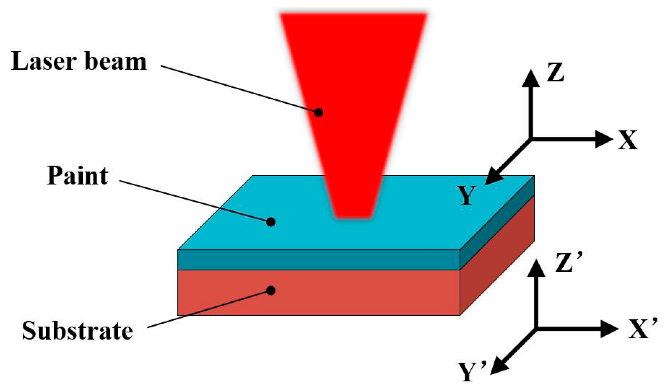
2.1. Experiment Setup

The sample surfaces are irradiated while utilizing a CW fiber laser (YLS-2000, IPG Photonics, Oxford, MA, USA) with a maximum average power of 2 kW, wavelength of 1070 nm. The laser beam spot is perpendicular to the substrate surface and the laser spot size is 5.0 mm. The beam quality factor (M2) is 1.2 measured by a laser beam quality analyzer (SP620U). The laser head is installed on a six-axis robot arm (ABB, Zürich, Switzerland). The auxiliary device includes a water-cooled chassis for the laser and an argon canister, which serves to protect the laser head lens. Argon process gas is blown over the surface in this case, in order to minimize the combustive effects. The nozzle assembly protects the system optics that allows for protective airflow through the lens to prevent combustion products from depositing on the front surface (Figure 1b). Figure 1a presents a schematic diagram of the experimental setup.
In this experiment, a 5A06 aluminum alloy substrate with the size of 40 × 20 × 2 mm3 is utilized as the samples. The main elementary composition is tested by X-ray fluorescence spectrometer (AXIOS-PW4400, Panaly, Dutch), as shown in Table 1. A unique treatment is taken to prepare the ‘man-made’ paint layer. Specimens of 40 mm × 20 mm dimensions were first polished with 1000 grade emery paper and then cleaned with ethyl alcohol before coating. Spray painting placed epoxy polyester (EP) paint and the paint thickness was checked while using the MEGACHECK 5FN-5F-ST instrument (Milliguang International Trading Co. Ltd, Munich, Germany). It was found to be a thickness of around 200 µm for protection. Optical microscopes examined the cleaned samples (Stemi 2000-C, Zeiss, Atlanta, GA, USA) and scanning electron microscopy characterized the surface images (SU3000, Hitachi, Japan). In addition, the Surftest SJ-210 instrument (Sanfeng, Tokyo, Japan) was used to evaluate the roughness of the laser cleaned surfaces. The micro hardness of the cleaned surfaces was measured by a HVS-1000 micro hardness tester (Weiyi, China).

2.2. Theoretical Background

2.2.1. Cleaning Model

From the Zou’s research [16], it is demonstrated that thermal stress is the main mechanism in the CW laser process for paint removal. Thermal expansion generates the thermal stress and the temperatures of different samples are calculated based on the one-dimensional (1D) heat conduction equation. When the CW laser irradiates the paint layer of the surface, the adhesion of the paint and metal substrate in the model is affected by many factors [17]. The adhesion between the paint layer and the substrate can be regarded as the force between two parallel planes in order to simplify the model. According to Tam et al. [18] and Kelley [19], the adhesion of paint to metal was calculated as the Lifshitz–van der Waals force [20], which corresponded with the simplified model. Although the amount of deformation depends on the hardness of the paint and surface of the substrate, the strong adhesion force can cause most substances to deform [18,19,20]. The adhesion between two parallel planes is
f = h 8 π 2 z 3
In Equation (1), h is the Lifshitz–van der Waals constant [17]. z is the atomic separation between the bottom surface of the particle and the substrate surface. The Lifshitz–van der Waals constant h is related to the Hamaker coefficient, by equation h = 4πA/3 [18,20].

2.2.2. Temperature Profiles

The first law of thermodynamics gives a general governing equation in the form of a differential equation that describes the temperature distribution of time and space functions, as shown in Equation (2). The one-dimensional finite difference thermal model is developed in parallel with experimental work for the evaluation of temperature history and the postulating laser interaction mechanism. The time-dependent temperature distribution is explicitly calculated according to the central difference discretized formula [21] of Fourier’s second law, i.e., from:
d T d t = k ρ C p × 2 T ( z , t ) z 2
where T is temperature, z the depth, k the thermal conductivity, Cp the specific heat, and ρ is the density. This is the more convenient form when addressing phase change [22], and it is in line with the derivation of the equation. Assuming constant CW laser irradiation and no radiant heat loss, the boundary conditions are:
k d T d z | z = 0 = P ( 1 R ) A
d T d z | z = = 0
At T(z, 0) = 298 (K)
where P is the input laser power, A is the beam area, and R is the reflectivity. A solution is:
T ( z , t ) = 2 I 0 R ( α t ) 1 / 2 i e r f c ( z 2 α t )
where α is the thermal diffusivity, ierfc is the so-called integral of the complementary error function [21]. The change in temperature can be computed while using Equation (7).
Δ T = T ( z , t ) T ( z , 0 )

2.2.3. Thermal Stress Profiles

As the substrate absorbed the laser energy, it is apparent that the temperature of it increases during the laser interaction time, which causes the surface of the substrate to thermally expand. Hence, the stress and strain are generated. In general, the substrate is regarded as an isotropic elastomer [22], and the stress per unit area of the isotropic elastomer is:
σ = Y ε = Y γ Δ T
where Y is the elastic modulus, ε is strain, and γ is thermal expansion coefficient.
When the laser irradiates on the surface of the paint, it will be reflected, absorbed, and transmitted.
It is shown that the irradiation of the paint and substrate with a laser beam and the Cartesian coordinate systems are set up on the paint (x, y, z) and the substrate (x’, y’, z’), as shown in Figure 2.
The following heat conduction equation is established under the following assumptions: (i) the laser intensity is Gaussian shape in the xy plane, (ii) the laser intensity in the z direction follows the law of absorption, (iii) the xy plane is approximately infinite plane, and (iv) both sides of paint and substrate are insulated.
For the laser stripping the paint, the thermal stress causes the paint to fall off is mainly composed of the thermal stress of the paint at z = −l ( σ P ) and the substrate’s thermal stress at z’ = 0 ( σ S ). The thickness of the paint is assumed to be l. The total thermal stress [23] is:
σ A = σ P + σ S
In most cases, the total thermal stress is divided into two parts, the paint stress and the substrate stress. The object is considered as a homogeneous elastic mass, so the thermal stress per unit area of paint at z = −l is given by
σ P = Y P ε P = Y P Δ l P l P = Y P γ P Δ T P ( l , t )
The thermal stress that arise by the thermal expansion of the substrate at the z’ = 0 position is as follows:
σ S = Y S ε S = Y S Δ l S l S = Y S γ S Δ T S ( 0 , t )
The force making the paint separate is mainly the thermal stress at the interface between the paint and substrate. If the paints want to be cleaned completely, which needs to meet:
σ A = σ P + σ S f A
where f A is the adhesion between the substrate and the paint.

2.3. Calculation of the Adhesion and the Cleaning Force

For one thing, the adhesion between the paint layer and the substrate can be obtained from Equation (1), Al substrate’s the Hamaker coefficient A11 is 35 × 10−20 J, the paint layer’s Hamaker coefficient A22 is about 8 × 10⁻²⁰ J, and the Hamaker coefficient A12 is approximately 16.73 × 10⁻²⁰ J, according to the formula A12 = A 11 A 22 . Thus, the Lifshitz–van der Waals constant h on Al alloy substrate is 70.08 × 10⁻²⁰ J. According to Equation (1), the adhesion force per unit area is 1.34 × 10⁸ Pa between the Al substrate and paint surface.
For another, in order to get the cleaning force, if the solutions for the temperature distributions have been measured, the accompanied thermal stress distributions can be derived from Equations (10) and (11). The temperature of the paint and the substrate is monitored by an infra-red thermometer (E75 Series, FLIR, Yishun, Atlanta, GA, USA). It is found that the paint, substrate, and room temperature are the same at 27 °C, while T P and T S are 59 and 90 °C, respectively. It is apparent that the Δ T P = 32   K the Δ T S = 63   K . The value of elasticity modulus Y P and Y S are 1.0 × 10¹⁰ N·m−2 and 7.0 × 10¹⁰ N·m−2 correspondingly, due to the physical parameters of 5A06 aluminum alloy and paint, as shown in Table 1. From the Table 2, the linear expansion coefficient γ P and γ S are 1 × 10⁻⁶ K−1 and 30 × 10−6 K−1, respectively. According to the Equations (10) and (11), the thermal stress is σ P = 3.2 × 10 5   Pa and σ S = 2.52 × 10 8   Pa , correspondingly. The necessary condition for stripping the paint layer can be obtained by the Equation (12). From it, the total cleaning force in per unit area is 2.52 × 10⁸ Pa, which is about twice larger than the adhesion force (1.34 × 10⁸ Pa), which makes it possible that paint can be thoroughly removed. In addition, the advantage of Equation (6), rather than their temperature based counterparts, is that they easily ignore phase change, which is a crucial component in laser processing [21,22].
Table 2 lists all of the physical parameters, including thermal and optical properties of 5A06 aluminum alloy and paint applied in the profiles. The values of reflectivity and transmissibility of paint and substrate are obtained by the device of double integrating sphere at a wavelength of 1064 nm.

3. Results and Discussion

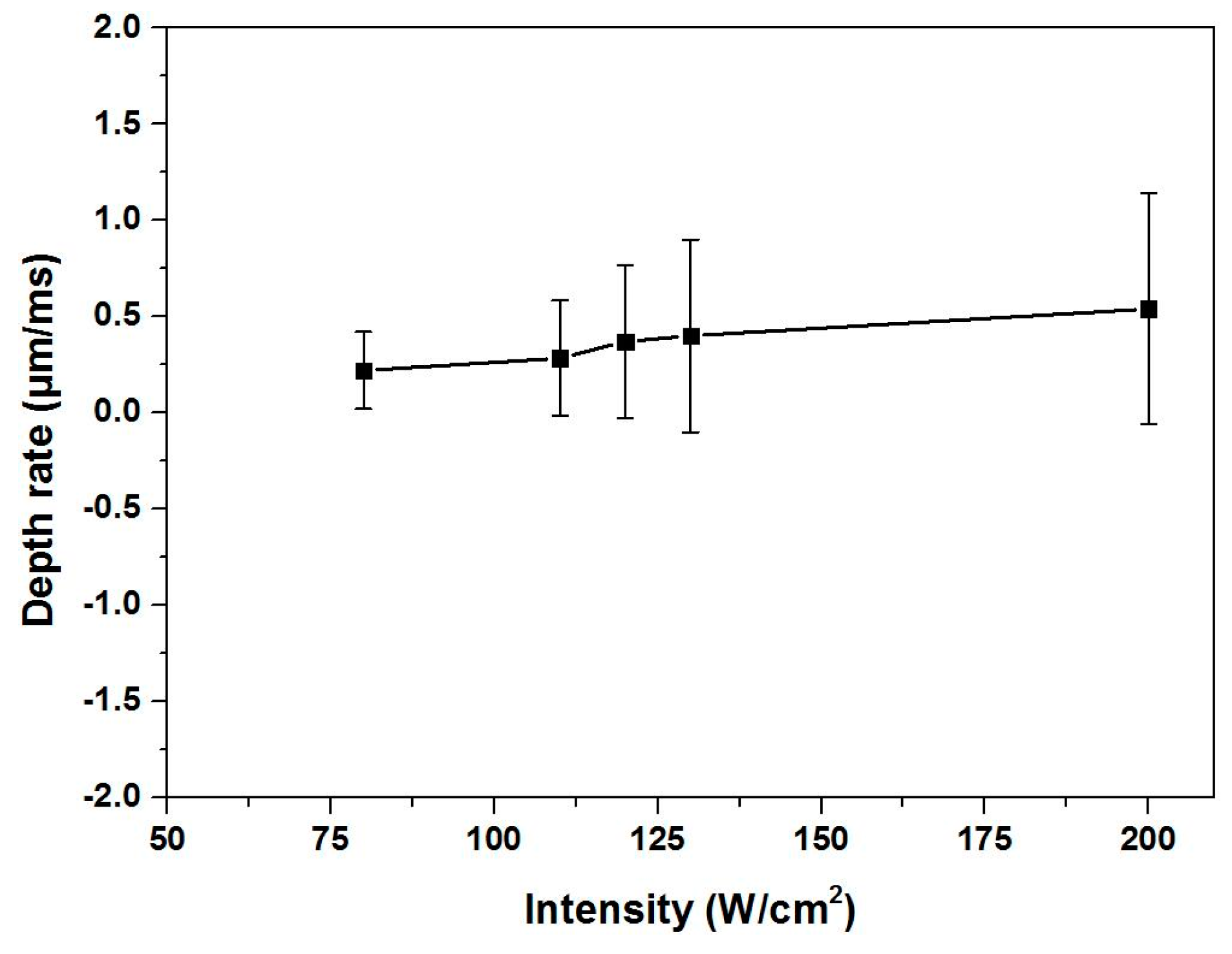
3.1. Removal Depth Rate
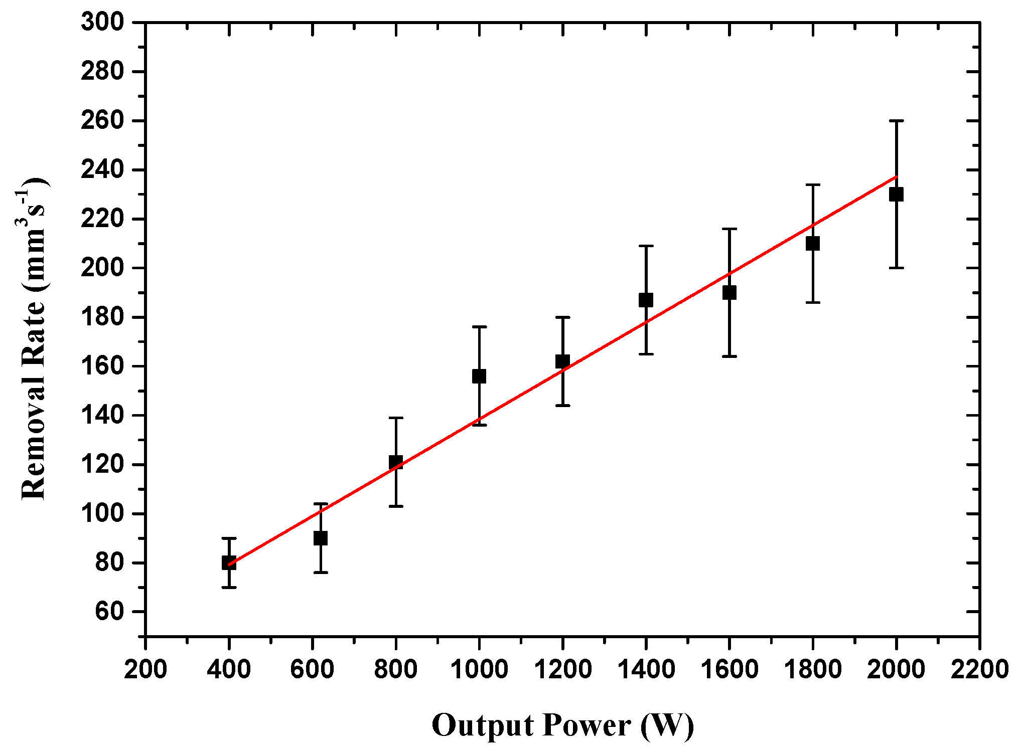
The removal depth rate in different intensity is an essential laser cleaning process parameter to ensure the surface of the substrate without ablation. It has been measured and analyzed to determine the ablation condition of the material, as shown in Figure 3. From it, it can be found the intensity and depth have a nearly linear relationship with the laser intensity increasing, which corresponds with the Beer–Lambert law [13]. It is conspicuous to find that the depth rate has a slight increase with the laser intensity increasing. It is because the higher the laser intensity is, the more likely it is to lead to the vaporization of the paint surface. Furthermore, as a result of the CW laser ablation the paint layer, it easily results in a significant dominance of the optical dissociation process during thermal dissociation [26]. The authors rely on the similarity of the ablation depth of the laser-induced combustion to the intensity although the residence time is in the region of a few hundred milliseconds or more [22,23,26].

3.2. Removal Rates

The removal rate is evaluated by a Taylor Hobson ‘‘Talysurf’’ surface profiling system for quantitative description of laser cleaning. The removed volume is then determined based on the lateral scanning speed over the coated surface, the width of the removed track and its depth, via:
R = ω v d
where R is the removal rate, v the transverse scanning speed, w the track width, and d the depth of the track in equation. As some paints could not be thoroughly cleaned, the error margin is estimated to be approximately 10% on the depth measurements.
It is the removal rate versus the CW laser output powers, as shown in Figure 4. It can be seen that the removal rate linearly varies with the CW laser output power. It is also shown in the process of using a low power pulse laser system [11,12,13], hence a similar removal process is proposed.

3.3. Optimization of Parameters on Laser Cleaning

Figure 5 shows the laser power versus scanning speed process window of the ablation area, completely cleaned area, and incompletely cleaned area parameters, respectively. The plane of coordinates of Figure 5 is divided into three regions, insufficient parameters region I, available parameters region II, as well as excessive parameters region III. The insufficient parameters region I are on the left, the parameters of which could make the incompletely cleaned area. The excessive parameters region III is on the right, parameters in which would make the substrate ablation. The available parameters region II is in the middle, the parameters of which would make the surface smooth and completely cleaned area.

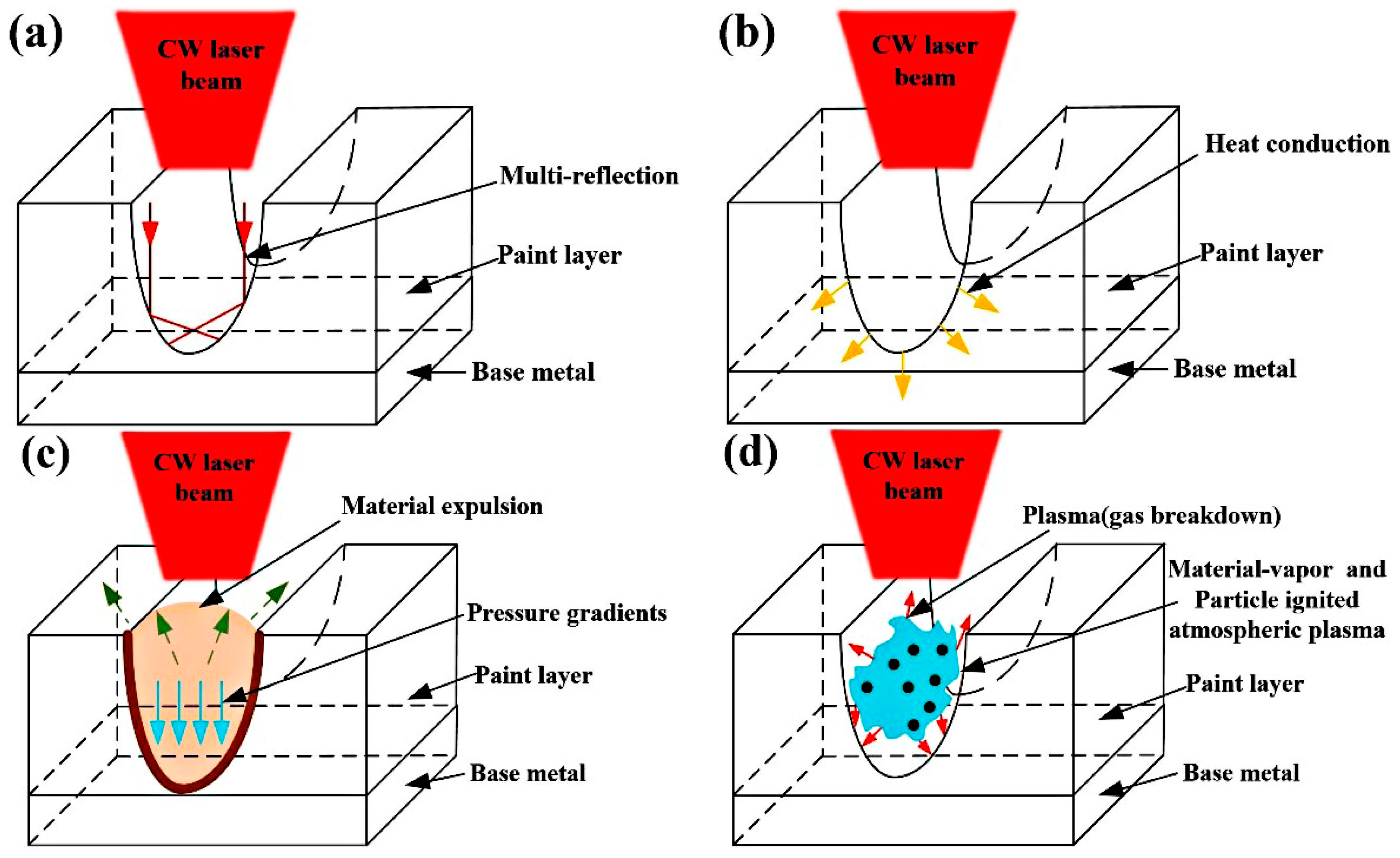
3.4. The Analysis of CW Laser Cleaning Process

The dry laser cleaning mode relies on the laser-induced generation of acoustic shocks, photochemical and photo thermal bond-breaking, or ablative removal of the contaminants on the surface [27]. For the CW laser ablation, there have been various models, including photochemical, photothermal, or a combination of photochemical and photothermal ablation mechanisms proposed to study the mechanism of it.
When the surface is treated with a CW laser with wavelengths 1070 nm, the laser beam will pass through the contamination layer and absorb large amount of energy in the layer itself. According to the high absorbance, the laser will couple into the coating that is near the surface and the energy will be converted into chemical and thermal ablation of the paint and cause local sublimation. This decomposition is accompanied by the formation of local plasma. The local pressure will enhance for the sublimation of the paint and the lower density of the generated vapor [28,29]. This will result in a pressure differential between the decomposition and the atmosphere above the contaminated layer. Finally, it will trigger a local burst of the covering contaminated layer and the residues will break and peel off the surface. Detailed information regarding the thermal ablation is discussed below.
Figure 6 presents the underlying ablation mechanism for CW laser cleaning. Firstly, as the initial stage of laser ablation, vaporization and phase explosion will occur during the low intensity cleaning process. In addition, the ablation depth of paint layer will be restricted due to the effect of multiple reflections (Figure 6a) on the incident laser intensity distribution on the surface of the paint layer. It is well known that vaporization is the primary mechanism at low incident intensity. Secondly, it shows the heat conduction during the ablation process in Figure 6b. The temperature at bottom of the crater declines due to the thermal diffusion, thus inhibiting the ablation rate [30,31]. Thirdly, the atmospheric plasma is easily caused by laser-induced air breakdown at higher incident laser intensity during the CW laser ablation process, as shown in Figure 6d. A material vapor-plasma is generated near the bottom of the crater, which can only be produced where material vapor is present. In addition, the particles ignited atmospheric plasma is at some distance from the bottom of the crater, and the particles that are still present in the crater after the previous laser irradiation promote its formation. In fact, during the entire ablation process, the laser induced plasma also produces an enormous pressure gradient, along with the direction of crater depth, as shown in Figure 6c. Additionally, the outflow of the gaseous or liquid material from the hole is achieved by pressure gradients that are within the crater. The formation of the plasma inside the crater at a distance from the bottom will locally increase the pressure strongly and create a pressure gradient that enforces the material to flow in a direction towards the bottom, which thus causes agglomeration on the surface of the crater [32].

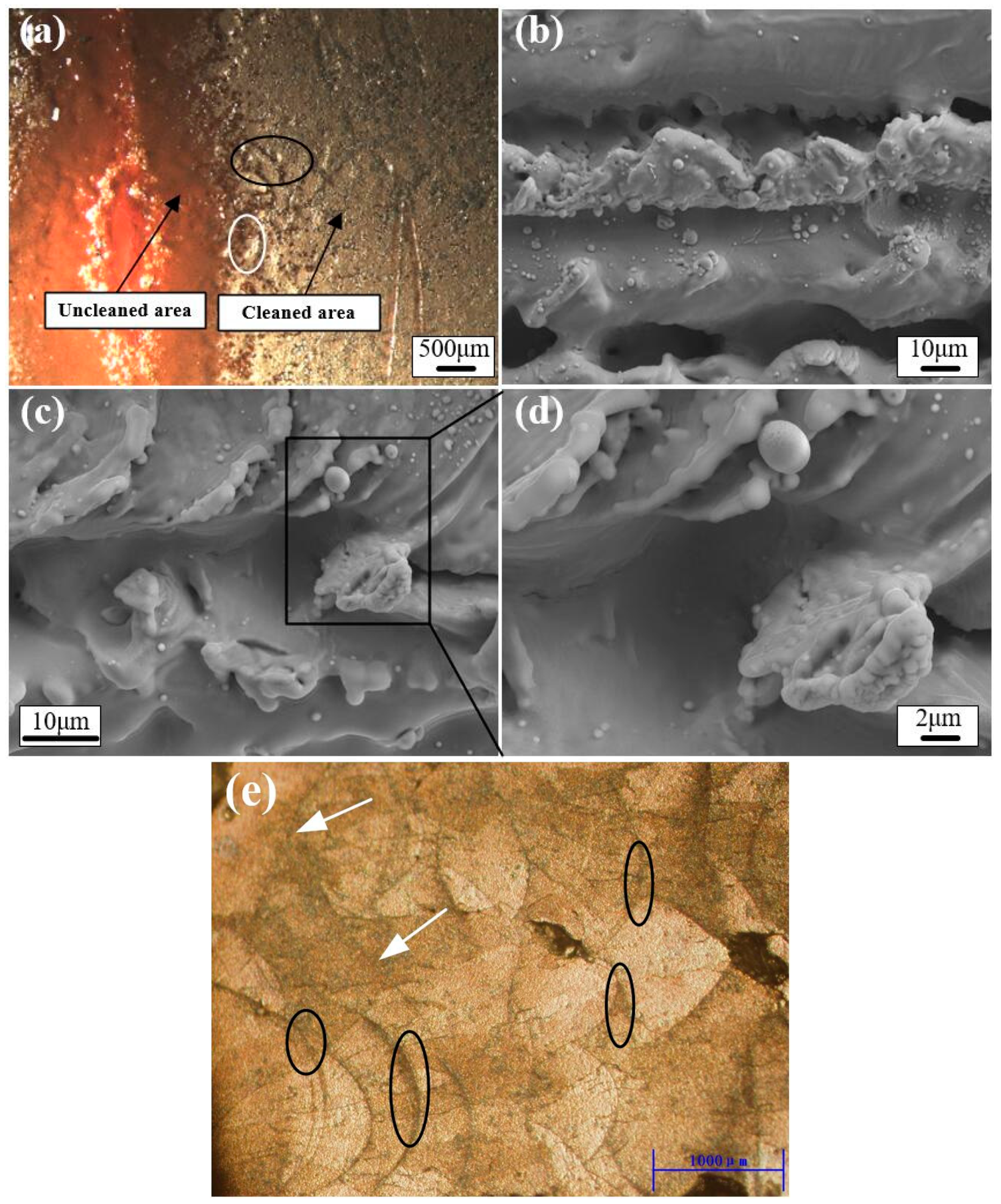
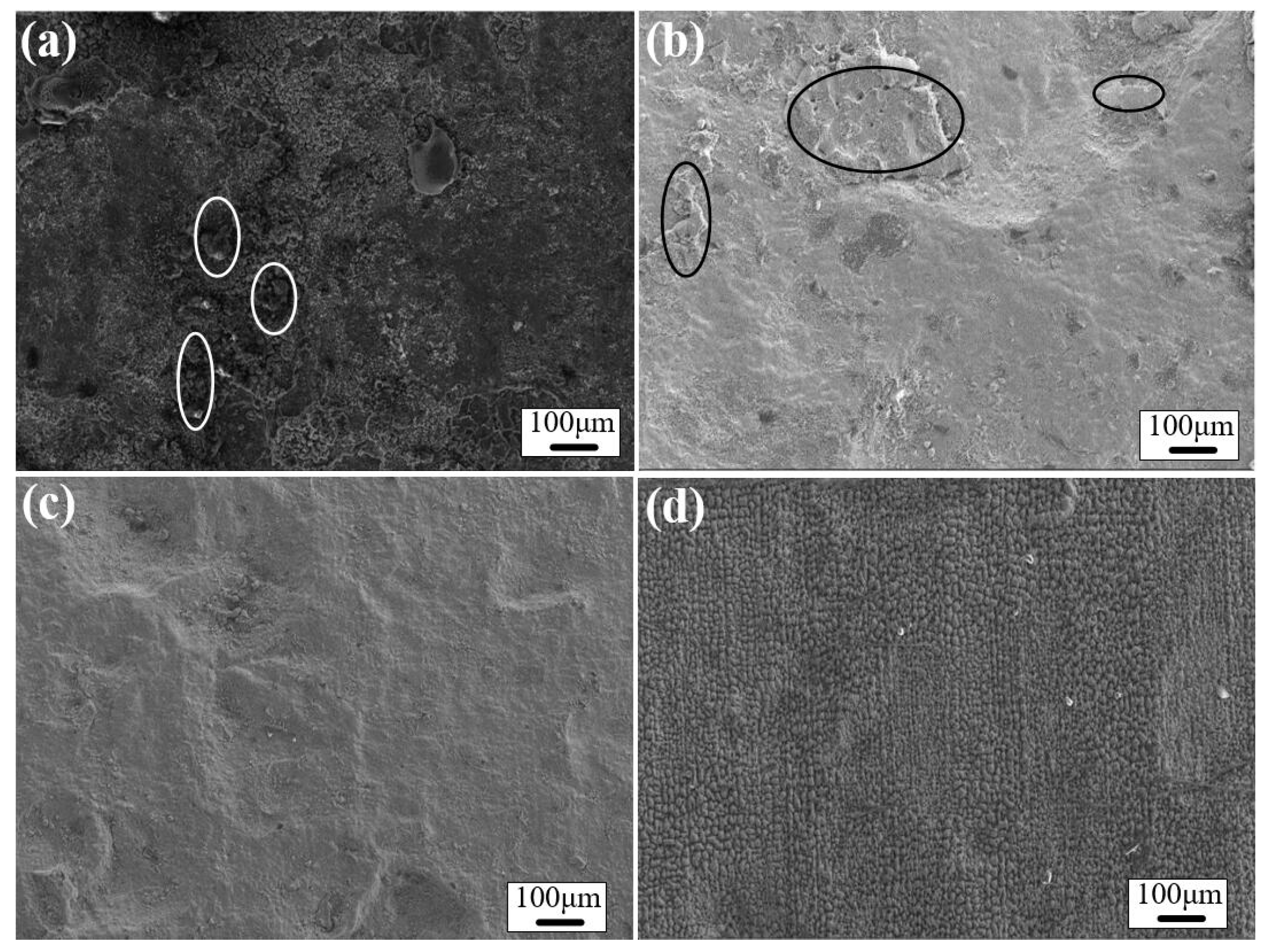
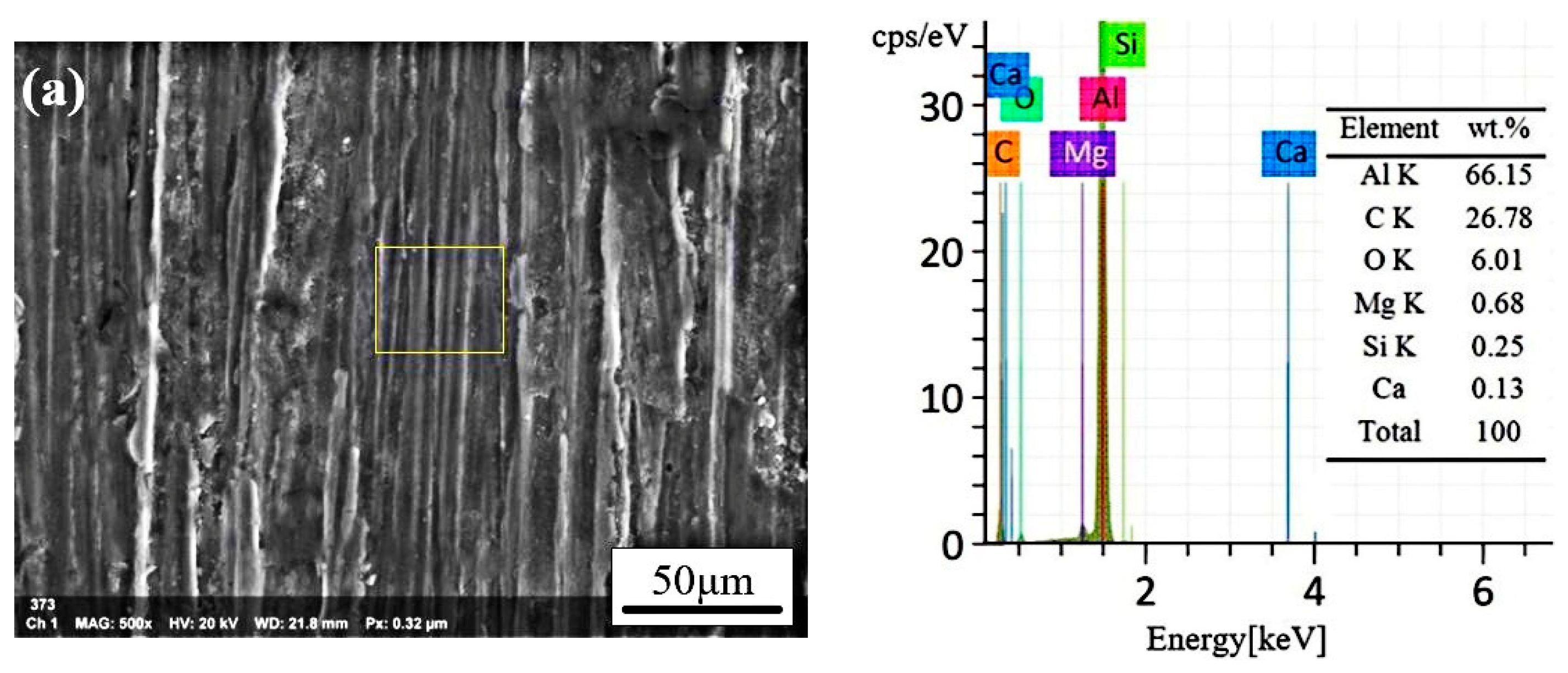
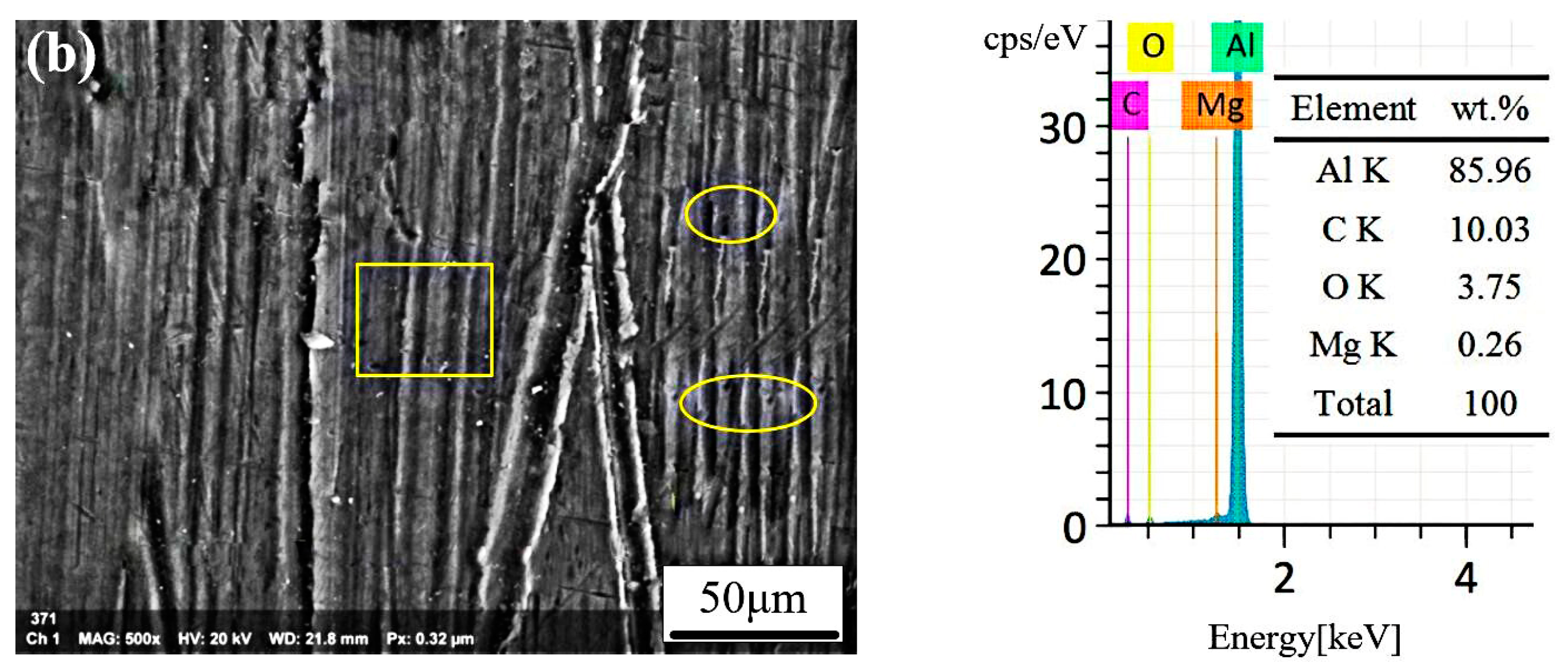
3.5. Morphology Analysis of the Cleaned Surfaces

Figure 7 exhibits the photomicrograph of the uncleaned area and the laser cleaned surface. The SEM images of the laser remelted surface layer are shown in Figure 7b–d. We decide to focus on the areas (black ellipse in Figure 7a) and the (white ellipse in Figure 7a) in order to investigate the surface laser remelting the microstructure in detail, which are attributed to the fact that it is easy to form the laser remelted microstructure at the edge of the cleaned area. From Figure 7b, it can be seen that there are some protrusions and microstructure on the surface, due to surface laser remelting. In Figure 7c, their surfaces are comprised of volcano-like microsized aggregates as a result of the laser ablation and Figure 7d illustrates the magnification image of black box area in Figure 7c). After laser melting, solidification began with epitaxial growth on the substrate to produce resolidified grains. From the black ellipse in Figure 7e, a significant amount of cellular dendrites were developed within the grains, resulting in a very fine microstructure with β -phase Al3Mg2. It is corresponded with the researcher focusing on the microstructure of an Al alloy that was treated by laser surface remelting [33,34,35,36,37,38,39]. From the previous research, the microstructure become cellular dendritic with precipitation of β -phase Al3Mg2 in the interdendritic region, which start to precipitate along the grain boundaries due to fast cooling rate of laser processing [33,34,35,36,38,39,40].
Although the microstructural refinement is hardly desired by major foundry industries in order to increase the mechanical properties, the corrosion resistance can be significantly affected [33]. In this particular case, such a tendency of enhancement on the corrosion resistance that is induced by the LSR process is associated with an increase of boundaries between the β -phase Al3Mg2 that have similar growth behaviors [33,34,35,36,37]. The boundaries are conformed due to a certain deformation on the atomic level, mainly on the β -phase Al3Mg2 side of the interface. Such localized deformation on the β -phase Al3Mg2 induces an increase on the corrosion action for very fine microstructures (laser remelted samples). Recent studies [3,17,33,34,35,36,37,38,39,40,41,42] dealing with the corrosion resistance of Al alloys have reported a similar result, with β -phase Al3Mg2 refined microstructures being connected to an increase in the corrosion resistance. The corrosion resistance of the laser cleaned surface will be discussed in detail in Section 3.6.3.
Figure 8 illustrates the SEM images of the CW laser cleaned surface at different intensities. The CW laser treated surface morphology is quite different from the as-received surfaces, which contain uneven and porous structures, as shown in (Figure 8a). It is noteworthy that it has a rough surface with micro-cracks and a great number of protrusions, on the surface morphology in the paint layer (white ellipse in Figure 8a). Furthermore, laser cleaning includes complex physical and chemical effects, which lead to the formation of local cracks and other craters (Figure 8b). It could be seen that there are some uncleaned areas (black ellipse in Figure 8b), which are attributed to the threshold of the laser cleaning that could not be achieved. After reaching the threshold of laser cleaning, it can be seen that there is a relatively even surface at laser intensity 11.9 W/cm2 and it contains few cracks and craters in some particular areas, as shown in Figure 8c. Except for the microsized structures, their surfaces are comprised of volcanic microscopic aggregates due to the excessive ablation in Figure 8d. With increasing laser intensity, the width and depth of the melted layer increased, and the grain size of the melted layer became coarser due to the higher heat input [43,44,45,46]. Section 3.4 illustrated the detailed multiple physical procedures. The detailed relationship between laser parameters and performance is shown in the laser cleaning to completely remove the EP paint layer.
Figure 9 shows the EDS spectrums of aluminum alloy sheets with the paints, which are incompletely cleaned samples and cleaned samples, as shown in Figure 9a,b. The parameters of the incompletely cleaned sample are a laser intensity of 6.2 W/cm2 and a scanning speed 300 mm/s. The parameters of the completely cleaned sample are laser intensity 11.9 W/cm2 and the scanning speed 300 mm/s. Both are scanned once. The cleanliness of the laser cleaned sample is characterized by the EDS spectrums, as shown in Figure 9. From it, the EDS spectrums of the incompletely cleaned sample show the characteristic peaks of aluminum, carbon and a minor peak of oxygen, magnesium, silicon, and calcium. From the Table 1, the percentage of the Al element accounts for about 91.6% in the Al alloy substrate. When the laser intensity is 11.9 W/cm2, the aluminum element accounts for 85.96% in the EDS spectrums, which is about 1.5 times larger than that in Figure 9a. However, the O content (6.01 at.%) in the incompletely cleaned surface is ranking first, which is about two times larger than that in completely cleaned surface (3.75 at.%). It is indicated that a relatively cleaned surface is obtained from the result. In conclusion, we get the laser completely cleaned surface through the SEM images and the EDS analysis, and after that we will investigate the performance of the 5A06 aluminum alloy to obtain better surface roughness, microhardness, and corrosion resistance.

3.6. Performance of the Laser Cleaned Surface

3.6.1. Surface Roughness

Surface roughness is a critical parameter in evaluating the cleaned quality [31,32,40]. It does not only affect the appearance and the surface accuracy, but it also directly influences the service life of the work piece. Table 3 and Table 4 list data on the effects of laser processing parameters on the cleaned surface roughness. It is indicated that roughness of the laser cleaned surface decreases firstly, while it increases with the laser intensity enhancing, as shown in Table 3.
As can be seen from the data in Table 4, the roughness of the laser cleaned surface increases with the scanning speed enhancing. The fact is that the CW laser cannot adequately irradiate the paint layer at a faster scanning speed. Furthermore, it can be found that the roughness of laser cleaned surfaces can remain unchanged by coordinating different laser cleaning parameters.

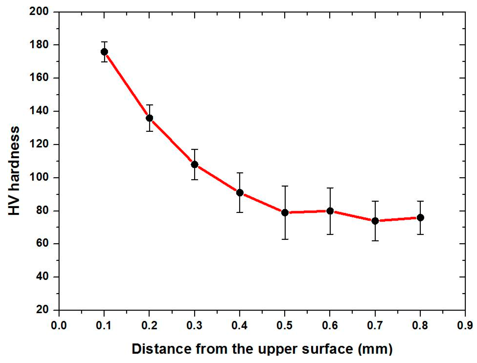
3.6.2. Surface Microhardness

Figure 10 draws data regarding the Vickers microhardness (with the load of 100 g) of samples. After the laser cleaning the lacquered sheet, multiple points are selected on the upper surface and the cross section of the scan line for hardness measurement. The parameters of the completely cleaned sample are a laser power of 800 W, scanning speed of 150 mm/s, and spot diameter of 8 mm. The micro hardness of the cleaned surfaces increases faster near the center of the scan line, as can be seen from Figure 9. In addition, it can be found that the closer to the surface of the substrate, the higher micro hardness value is on the cross section of the scan line. It can be deduced that the farther distance from the upper surface is substantially unaffected with the HV hardness, as can be seen from the Figure 11.
In conclusion, there are two possible reasons that would enhance the hardness: (1) rapid melting and then quenching produce dense strip-shaped Micro-nano groove and the periodic microstructures (especially the relatively small grain size) during CW laser irradiation. (2) The CW laser induces the dislocation density of the cleaned surface [40,43]. This is a unique advantage of laser cleaning technology as compared to other traditional cleaning methods.

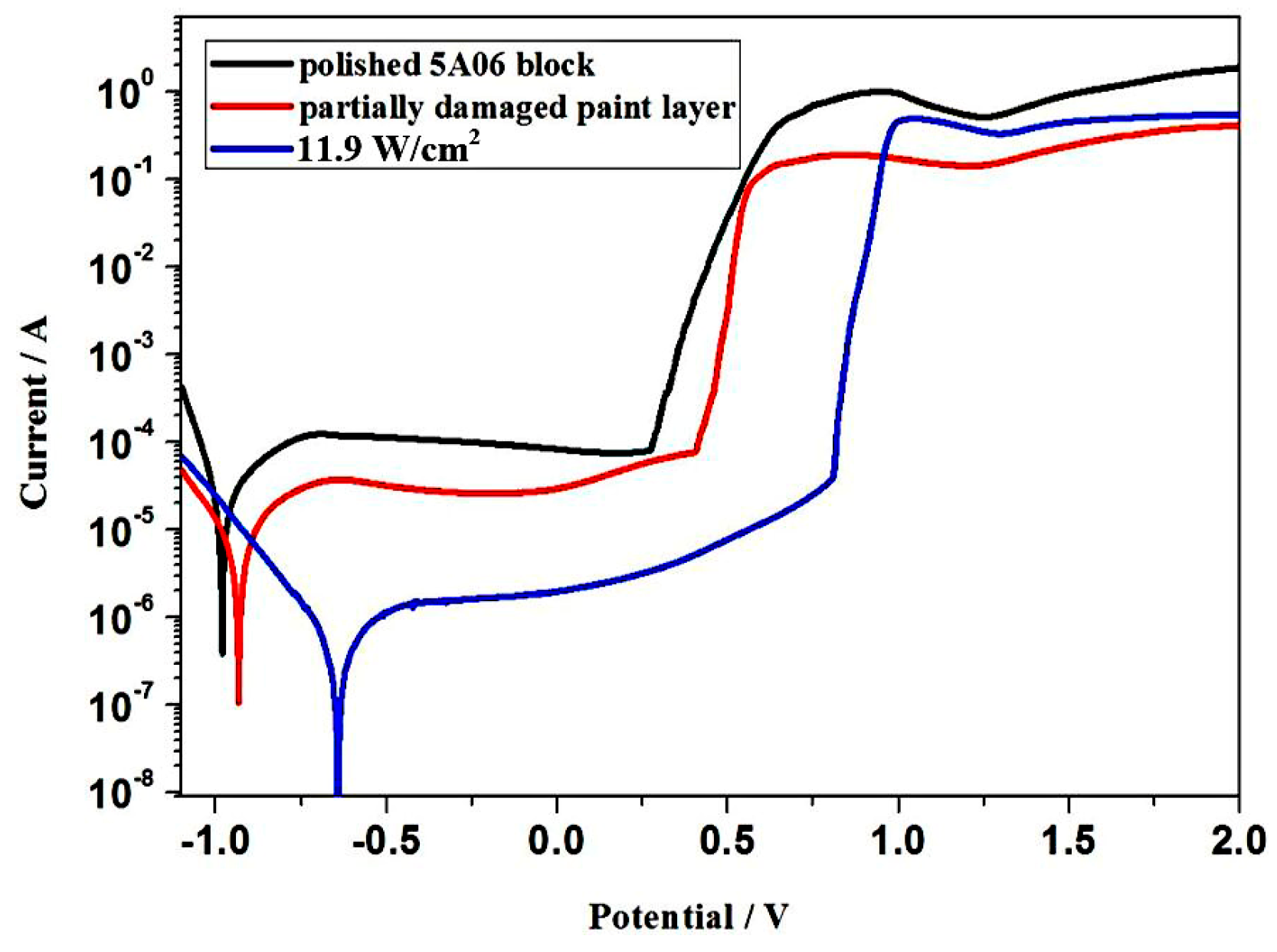
3.6.3. Corrosion Resistance

The metal surface will be damaged if the metal is constantly immersed in a liquid environment for a long time and it causes continuous corrosion, and it is very necessary to improve the corrosion resistance of the metal for marine applications [47]. After the ship has sailing in the sea a long time, the paint layer is damaged as a result of the sea corrosion. The metal substrate would directly contact the seawater, so it is essential to enhance the corrosion resistance of it, which is good for prolonging the service life of the ship, followed by the re-painting work. For 5A06 aluminum, when the paint layer is partially damaged, the corrosion resistance of the surface will not enhance, and it will accelerate the electrochemical corrosion reversely. It is apparent that the laser cleaned surface can effectively improve the corrosion resistance of the material surface, so the use of this method on 5A06 aluminum products is of great significance. We decide to conduct an electrochemical corrosion resistance analysis of the surface to test the corrosion resistance of the prepared samples and measure the Tafel curve and EIS of the sample in a 3.5 wt % NaCl solution at room temperature. The Tafel curves of the polished 5A06 aluminum block, partially damaged paint layer and the laser treated 5A06 aluminum surface at an intensity of 11.9 W/cm2 are shown in Figure 12. Some of the parameters related to the Tafel curves are listed in Table 5, such as corrosion potential (Ecorr), corrosion current density (icorr), and the inhibition efficiency (ηIE), where ηIE can be obtained by the formula [48]:
η IE = i 0 i corr i 0 × 100 %
where i 0 and i corr are the current density of the polished 5A06 aluminum block and laser treated surface respectively.
Generally, higher corrosion potential and lower corrosion current density represent better corrosion resistance [49]. The data shows that, after laser cleaned surface, the anticorrosion potential of is improved when compared with the polished 5A06 aluminum block surface, while the corrosion current density reduced. The previous research shows the thickness of the rust layer has great influence on the corrosion current density [50]. The Ecorr of the polished 5A06 aluminum block surface was −9.03 × 10⁻¹ V, in contrast, the Ecorr of the partially damaged paint layer and the laser treated 5A06 aluminum surface at an intensity of 11.9 W/cm2 were −8.61 × 10⁻¹ and −6.39 ×10⁻¹ V, correspondingly. The icorr of the polished 5A06 aluminum block surface was 3.538 × 10⁻⁴ A cm−2, partially damaged paint layer was 7.42 × 10⁻⁵ A cm−2, the laser cleaned surface at an intensity 11.9 W/cm2 was 5.145 × 10⁻⁵ A cm−2, and the corrosion current density of laser cleaned surfaces reduced so much. As for ηIE, they were calculated that partially damaged paint layer was 79.02% and laser cleaned surface at an intensity of 11.9 W/cm2 was 85.46%. It is indicated that the CW laser cleaned surface has better corrosion resistance, while the partially damaged paint layer is not as well. It is because the paint layer has been stripped completely and the laser cleaned surface is quite flat with compact micro- or nanostructure, which makes some contributions for enhancing the corrosion resistance significantly [40]. Thus, the laser cleaned surfaces performs with better corrosion resistance.
As the laser surface treatment is characterized by rapid heating and cooling of the laser, which makes the surface structure, composition and stress of the material uniform, which thereby reduces the difference in surface free energy, declining the electromotive force of the local galvanic cell and finally achieving the goal of better corrosion resistance. According to Escudero et al. and Van Ingelgem et al. [51,52], they have investigated the structure of the material and fine-grained cementite and austenite areas, which enhances the corrosion resistance of the material. It corresponded with the experimental results, like Figure 8c, which has fine-grained and uniform surface structure as compared with the other laser cleaned surface. Thus, it is very significant to clean the partially damaged paint layer of the ship in order to prolong the lifetime of the ship.

4. Conclusions

In this work, investigation regarding the CW laser cleaning the aluminum alloy substrate covered with the paints is carried out. The removal rates linearly increase with the CW laser output power. The optimization of the parameters on laser cleaning would modify the surface smoothly and cleanly from the experiment. The experiment result is in reasonable accordance with theoretical model and the analysis of CW laser cleaning process, which proves the rationality of it. The morphology analysis of the cleaned surfaces demonstrates that the cleaned surface of 5A06 aluminum alloy substrate could be achieved at suitable laser cleaning parameters. The results in our study can provide a theoretical foundation for the investigation of a laser–paint interaction mechanism and the evaluation of the performance characteristic at different parameters. From the experimental result, it shows that the laser cleaned surface at an intensity of 11.9 W/cm2 has better corrosion resistance when compared with the polished 5A06 block. Therefore, it is suggested that there is great potential to use this method to clean the paint layer on the surface of the ship in order to prolong the lifetime of the ship. In addition, further work still needs to be paid attention to the relationship between the parameters of the laser cleaning and the morphology of the Micro-nano groove microstructure followed by the adhesion of the paint. The CW laser cleaning would be a promising technology for applications of the marine ship industrial.

Author Contributions

Conceptualization, B.G. and L.Y.; Methodology, Y.W.; Validation, L.Y., Y.W. and B.G.; Formal Analysis, H.C.; Investigation, H.C.; Data Curation, Y.L.; Writing—Original Draft Preparation, Y.L.; Writing—Review and Editing, Y.L.; Supervision, Z.T.; Project Administration, Y.W.; Funding Acquisition, L.Y.

Funding

This research was funded by National Key Research and Development Program, grant number 2017YFB1105000 and The APC was funded by LiJun Yang.

Acknowledgments

Thanks for the Dalian shipbuilding industry company for providing the materials used for experiments.

Conflicts of Interest

The authors declare no conflict of interest.

References

  1. U.S. Department of the Navy Carderock Division; Naval Surface Warfare Center; Peterson Builders Inc. The National Shipbuilding Research Program: Surface Preparation and Coating Handbook; IIT Research Institute: Chicago, IL, USA, 1994. [Google Scholar]
  2. Chen, G.X.; Kwee, T.J.; Tan, K.P.; Choo, Y.S.; Hong, M.H. High-power fibre laser cleaning for green shipbuilding. J. Laser Micro Nanoeng. 2012, 7, 249–253. [Google Scholar] [CrossRef]
  3. Ke, L.; Zhu, H.; Lei, W.; Cheng, Z. Laser cleaning of rust on ship steel using TEA CO2 pulsed laser. In Photonics and Optoelectronics Meetings (POEM) 2009: Industry Lasers and Applications; International Society for Optics and Photonics: Bellingham, WA, USA, 2009; Volume 7515, p. 75150. [Google Scholar]
  4. Chen, G.X.; Kwee, T.J.; Tan, K.P.; Choo, Y.S.; Hong, M.H. Laser cleaning of steel for paint removal. Appl. Phys. A 2010, 101, 249–253. [Google Scholar] [CrossRef]
  5. Madhukar, Y.K.; Mullick, S.; Shukla, D.K.; Kumar, S.; Nath, A.K. Effect of laser operating mode in paint removal with a fiber laser. Appl. Surf. Sci. 2013, 264, 892–901. [Google Scholar] [CrossRef]
  6. Schweitzer, G.; Werner, L. Industrial 2 kW TEA CO2 laser for paint stripping of aircraft: Gas flow and chemical lasers. In Proceedings of the SPIE 2502, Gas Flow and Chemical Lasers: Tenth International Symposium, Friedrichshafen, Germany, 5–9 September 1994; pp. 57–62. [Google Scholar]
  7. Tsunemi, A.; Hagiwara, K.; Saito, N.; Nagasaka, K.; Miyamoto, Y.; Suto, O.; Tashiro, H. Complete removal of paint from metal surface by ablation with a TEA CO2 laser. Appl. Phys. A 1996, 63, 435–439. [Google Scholar]
  8. Schroeder, K.; Schuocker, D. Ultrahigh-power lasers and their industrial applications. Laser Phys. 1998, 8, 38–46. [Google Scholar]
  9. Gobernado Mitre, I.; Prieto, A.C.; Zafiropulos, V.; Spetsidou, Y.; Fotakis, C. On-line monitoring of laser cleaning of limestone by laser-induced breakdown spectroscopy and laser-induced fluorescence. Appl. Spectrosc. 1997, 51, 1125–1129. [Google Scholar] [CrossRef]
  10. Strauter, C.; Fontaine, J.; Engel, T.; Biernaux, A. Optical and acoustical monitoring of material processing with q-switched Nd:YAG and excimer laser radiation. In Proceedings of the SPIE 2246, Laser Materials Processing and Machining, Frankfurt, Germany, 19–24 June 1994. [Google Scholar]
  11. Schmidt, M.J.J.; Li, L.; Spencer, J.T.; Key, P.H. A comparative study of the effects of laser wavelength on laser removal of chlorinated rubber. Appl. Surf. Sci. 1999, 138, 418–423. [Google Scholar] [CrossRef]
  12. Schmidt, M.J.J.; Li, L.; Spencer, J.T. Removal of chlorinated rubber coatings from concrete surfaces using a 120-W high power diode laser. J. Mater. Process. Technol. 2001, 141, 40–47. [Google Scholar] [CrossRef]
  13. Schmidt, M.J.J.; Li, L.; Spencer, J.T. An investigation into the feasibility and characteristics of using a 2.5 kW high power diode laser for paint stripping. J. Mater. Process. Technol. 2003, 138, 109–115. [Google Scholar] [CrossRef]
  14. Barletta, M.; Gisario, A.; Tagliaferri, V. Advance in paint stripping from aluminium substrate. J. Mater. Process. Technol. 2006, 173, 232–239. [Google Scholar] [CrossRef]
  15. Xu, X.; Willis, D.A. Non-equilibrium phase change in metal induced by nanosecond pulsed laser irradiation. J. Heat Transf. 2002, 124, 293–298. [Google Scholar] [CrossRef]
  16. Zou, W.-F.; Xie, Y.-M.; Xiao, X.; Zeng, X.-Z.; Luo, Y. Application of thermal stress model to paint removal by Q-switched Nd: YAG laser. Chin. Phys. B 2014, 23, 074205. [Google Scholar] [CrossRef]
  17. Lu, Y.F.; Song, W.D.; Ang, B.W.; Hong, M.H.; Chan, D.S.H.; Low, T.S. A theoretical model for laser removal of particles from solid surfaces. Appl. Phys. A Mater. Sci. Process. 1997, 65, 9–13. [Google Scholar] [CrossRef]
  18. Tam, A.C.; Leung, W.P.; Zapka, W.; Ziemlich, W. Laser-cleaning techniques for removal of surface particulates. J. Appl. Phys. 1992, 71, 3515–3523. [Google Scholar] [CrossRef]
  19. Kelley, J.D.; Hovis, F.E. A thermal detachment mechanism for particle removal from surfaces by pulsed laser irradiation. Microelectron. Eng. 1993, 20, 159–170. [Google Scholar] [CrossRef]
  20. Mittal, K.L. Particles on Surfaces 1; Plenum Press: New York, NY, USA, 1988; pp. 77, 129, 179. [Google Scholar]
  21. Turner, M.W.; Crouse, P.L.; Li, L.; Smith, A.J.E. Investigation into CO2 laser cleaning of titanium alloys for gas-turbine component manufacture. Appl. Surf. Sci. 2006, 252, 4798–4802. [Google Scholar] [CrossRef]
  22. Turner, M.W.; Crouse, P.L.; Li, L. Comparative interaction mechanisms for different laser systems with selected materials on titanium alloys. Appl. Surf. Sci. 2007, 253, 7992–7997. [Google Scholar] [CrossRef]
  23. Watkins, K.G. Mechanisms of laser cleaning. In Proceedings of the SPIE 3888, High-Power Lasers in Manufacturing, Osaka, Japan, 1–5 November 1999; pp. 165–174. [Google Scholar]
  24. Gathers, G.R. Thermophysical properties of liquid copper and aluminum. Int. J. Thermophys. 1983, 4, 209–226. [Google Scholar] [CrossRef]
  25. Pehlke, R.D.; Jeyarajan, A.; Wada, H. Summary of Thermal Properties for Casting Alloys and Mold Materials; University of Michigan: Ann Arbor, MI, USA, 1982. [Google Scholar]
  26. Schmidt, M.J.J.; Li, L.; Spencer, J.T. Removal of chlorinated rubber coatings from concrete surfaces using an RF excited CO2 laser. J. Mater. Process. Technol. 2001, 114, 139–144. [Google Scholar] [CrossRef]
  27. Jasim, H.A.; Demir, A.G.; Previtali, B.; Taha, Z.A. Process development and monitoring in stripping of a highly transparent polymeric paint with ns-pulsed fiber laser. Opt. Laser Technol. 2017, 93, 60–66. [Google Scholar] [CrossRef]
  28. Steen, W.M.; Mazumder, J. Laser Material Processing; Springer Science & Business Media: Berlin, Germany, 2010. [Google Scholar]
  29. Watkins, K.G. Mechanisms of laser cleaning. In High-Power Lasers in Manufacturing; International Society for Optics and Photonics: Bellingham, WA, USA, 2000; Volume 3888, pp. 165–175. [Google Scholar]
  30. Aden, M.; Beyer, E.; Herziger, G. Laser-induced vaporisation of metal as a Riemann problem. J. Phys. D Appl. Phys. 1990, 23, 655. [Google Scholar] [CrossRef]
  31. Knight, C.J. Theoretical modeling of rapid surface vaporization with back pressure. Aiaa J. 1979, 1, 519–523. [Google Scholar] [CrossRef]
  32. Chan, C.L.; Mazumder, J. One-imensional steady-state model for damage by vaporisation and liquid expulsion due to laser-material interaction. J. Appl. Phys. 1998, 62, 4579–4586. [Google Scholar] [CrossRef]
  33. Osório, W.R.; Cheung, N.; Peixoto, L.C.; Garcia, A. Corrosion resistance and mechanical properties of an Al 9 wt% Si alloy treated by laser surface remelting. Int. J. Electrochem. Sci. 2009, 4, 820–831. [Google Scholar]
  34. Watkins, K.; McMahon, M.; Steen, W. Microstructure and corrosion properties of laser surface processed aluminium alloys: A review. Mater. Sci. Eng. A 1997, 231, 55–61. [Google Scholar] [CrossRef]
  35. Li, R.; Ferreira, M.; Almeida, A.; Vilar, R.; Watkins, K.; McMahon, M.; Steen, W. Localized corrosion of laser surface melted 2024-T351 aluminium alloy. Surf. Coat. Technol. 1996, 81, 290–296. [Google Scholar] [CrossRef]
  36. Yasa, E.; Deckers, J.; Kruth, J.-P.; Kruth, J. The investigation of the influence of laser re-melting on density, surface quality and microstructure of selective laser melting parts. Rapid Prototyp. J. 2011, 17, 312–327. [Google Scholar] [CrossRef]
  37. Pan, Q.; Huang, W.; Song, R.; Zhou, Y.; Zhang, G. The improvement of localized corrosion resistance in sensitized stainless steel by laser surface remelting. Surf. Coat. Technol. 1998, 102, 245–255. [Google Scholar] [CrossRef]
  38. Yajie, L.; Fengming, Q.; Cuirong, L.; Zhisheng, W. Flow law, microstructure and corrosion behavior of friction stir welded 5A06 alloy. Rare Met. Mater. Eng. 2018, 47, 2353–2359. [Google Scholar] [CrossRef]
  39. Zhu, Y.; Cullen, D.A.; Kar, S.; Free, M.L.; Allard, L.F. Evaluation of Al3Mg2 precipitates and Mn-rich phase in aluminum-magnesium alloy based on scanning transmission electron microscopy imaging. Met. Mater. Trans. A 2012, 43, 4933–4939. [Google Scholar] [CrossRef]
  40. Wang, Z.; Zeng, X.; Huang, W. Parameters and surface performance of laser removal of rust layer on A3 steel. Surf. Coat. Technol. 2003, 166, 10–16. [Google Scholar] [CrossRef]
  41. Paliwal, M.; Jung, I.-H. The evolution of the growth morphology in Mg–Al alloys depending on the cooling rate during solidification. Acta Mater. 2013, 61, 4848–4860. [Google Scholar] [CrossRef]
  42. Wang, Y.; Li, C.; Tian, W.; Yang, Y. Laser surface remelting of plasma sprayed nanostructured Al2O3–13 wt% TiO2 coatings on titanium alloy. Appl. Surf. Sci. 2009, 255, 8603–8610. [Google Scholar] [CrossRef]
  43. Cui, Y.; Shen, J.; Hu, S. Microstructure and performance of the laser melted aluminum bronze layers with and without using activator. Mater. Res. Express 2019, 6, 066513. [Google Scholar] [CrossRef]
  44. Haixiang, C.; Dejun, K. Effect of laser remelting on amorphous formation and electrochemical corrosion of laser thermal sprayed Al–Ti–Ni coating. Mater. Res. Express 2019, 6, 086545. [Google Scholar] [CrossRef]
  45. De Freitas, F.E.; Perpetuo Briguente, F.; Reis, A.G.D.; Vasconcelos, G.D.; Pereira Reis, D.A. Investigation on the microstructure and creep behavior of laser remelted thermal barrier coating. Surf. Coat. Technol. 2019, 369, 257–264. [Google Scholar] [CrossRef]
  46. Qin, E.; Wang, B.; Li, W.; Ma, W.; Lu, H.; Wu, S. Optimized microstructure and properties of Cr3C2-NiCr cermet coating by HVOF/laser hybrid processing. J. Therm. Spray Technol. 2019, 28, 1072–1080. [Google Scholar] [CrossRef]
  47. Takenaka, T.; Ono, T.; Narazaki, Y.; Naka, Y.; Kawakami, M. Improvement of corrosion resistance of magnesium metal by rare earth elements. Electrochim. Acta 2007, 53, 117–121. [Google Scholar] [CrossRef]
  48. Yuan, S.; Pehkonen, S.; Liang, B.; Ting, Y.; Neoh, K.G.; Kang, E.-T. Superhydrophobic fluoropolymer-modified copper surface via surface graft polymerisation for corrosion protection. Corros. Sci. 2011, 53, 2738–2747. [Google Scholar] [CrossRef]
  49. Wang, H.; Dong, S.; Wang, Z. One-step fabrication of superhydrophobic surface on beryllium copper alloys and corrosion protection application. Colloids Surf. A Physicochem. Eng. Asp. 2018, 556, 291–298. [Google Scholar] [CrossRef]
  50. Dong, S.; Wang, Z.; Wang, Y.; Bai, X.; Fu, Y.Q.; Guo, B.; Tan, C.; Zhang, J.; Hu, P.; Fu, Y.Q.R. Roll-to-roll manufacturing of robust superhydrophobic coating on metallic engineering materials. ACS Appl. Mater. Interfaces 2018, 10, 2174–2184. [Google Scholar] [CrossRef]
  51. Escudero, M.L.; Bello, J.M. Laser surface treatment and corrosion behaviour of martensitic stainless AISI 420 steel. Mater. Sci. Eng. 1992, 158, 227–233. [Google Scholar] [CrossRef]
  52. Van Ingelgem, Y.; Vandendael, I.; Van den Broek, D.; Hubin, A.; Vereecken, J. Influence of laser surface hardening on the corrosion resistance of martensitic stainless steel. Electrochim. Acta 2007, 52, 7796–7801. [Google Scholar] [CrossRef]
Figure 1. Schematic diagram of experimental setup. (a) Actual experimental equipment. (b) Laser-nozzle-substrate arrangement used in the experiments.
Coatings 09 00488 g001
Figure 2. Simplified schematic diagram of paint removal by laser.
Coatings 09 00488 g002
Figure 3. The relationship between the removal depth rate and the intensity for epoxy polyester (EP) coatings.
Coatings 09 00488 g003
Figure 4. The removal rate of the EP paint achieved with the laser output power.
Coatings 09 00488 g004
Figure 5. Process window for (inset micrograph: I 300 mm/s, 6.2 W/cm2, II 300 mm/s, 11.9 W/cm2, III 300 mm/s, 19.1 W/cm2).
Coatings 09 00488 g005
Figure 6. Schematic illustration (ad) of the thermal ablation mechanism for Continuous wave (CW) laser cleaning.
Coatings 09 00488 g006
Figure 7. The photo-micrograph of the uncleaned and the laser cleaned area (a), (bd) are the according magnification images, (e) is the micrograph of the laser remelted surface etching with 0.5% HF solution. White arrows indicate grain boundary β -phase.
Coatings 09 00488 g007
Figure 8. SEM images of paint and laser treated surface at different intensity (a) paint layer, (b) 6.2 W/cm2, (c) 11.9 W/cm2, and (d) 19.1 W/cm2.
Coatings 09 00488 g008
Figure 9. SEM micrographs and EDS spectrums of samples (a) incompletely cleaned sample and (b) completely cleaned sample.
Coatings 09 00488 g009aCoatings 09 00488 g009b
Figure 10. Schematic diagram of hardness as distance from the center of the scan line.
Coatings 09 00488 g010
Figure 11. Schematic diagram of hardness as distance from the upper surface.
Coatings 09 00488 g011
Figure 12. Tafel curves of the rust, bare and laser treated sample at different fluence in 3.5 wt % NaCl solution.
Coatings 09 00488 g012
Table 1. Chemical components of ANSI 5A06 material (wt %).
AlSiCuZnMgMnTi
Ballance≤0.4≤0.1≤0.25.8~6.80.5~0.80.02~0.1
Table 2. Physical parameters of 5A06 aluminum alloy and paint [16,24,25].
Properties5A06 Aluminum Alloy Paint
Thermal Conductivity
(W/m·K)
2380.3
Density (kg/m3)27001300
Specific Heat Capacity
(J/kg·K)
10002510
Thermal Diffusivity (m2/s)8.8 × 10−89.19 × 10−8
Linear Expansion Coefficient (K−1)30 × 10−6 [25]1.00 × 10⁻⁶
Absorption Rate0.6420.614
Reflectivity0.358 [16]0.193
Transmittance0.193
Absorption Coefficient (m−1)10000 × 1042.27 × 104
Elasticity Modulus
(N·m−2)
7 × 10¹⁰ [24]1.0 × 10¹⁰
Table 3. The relationship between laser intensity and roughness on the cleaned surface.
Sample No.A1A2A3A4A5A6A7
I (W/cm2)3.36.27.011.913.615.319.1
Ra (μm)1.2471.3731.2910.9671.3081.4612.394
Other parameters: Vs = 300 mm/s; N = 1; D = 5 mm.
Table 4. The relationship between scanning velocity and the roughness on the cleaned surface.
Sample No.B1B2B3B4B5B6B7
Vs (mm/s)50100200300400500600
Ra (μm)3.2512.5333.2543.5254.0614.3355.042
Other parameters: I = 11.9 W/cm2; N = 1; D = 5 mm.
Table 5. Electrochemical parameters of the Tafel curves on the polished 5A06 block, partially damaged paint layer, and laser cleaned surface at 11.9 W/cm2.
SampleEcorr (V)icorr (A·cm−2)ηIE (%)
Polished 5A06 block−9.03 × 10−13.538 × 10−4
Partially damaged paint layer−8.61 × 10−17.42 × 10−579.02%
Laser cleaning at 11.9 W/cm2−6.39 × 10−15.145 × 10−585.46%

