Article

Hydrothermal Aging and Humidity Exposure of Carbon and Basalt Fibers and Life Time Prediction †

1
Department of Mechanical Engineering, University of Alberta, Edmonton, AB T6G 2R3, Canada
2
Flexpipe, Mattr Infrastructure Technologies, Calgary, AB T2C 0A9, Canada
*
Author to whom correspondence should be addressed.
This paper is an expanded version of a conference paper published in the proceedings of the 2023 Canadian Society for Mechanical Engineering International Conference, Sherbrooke, QC, Canada, 28–31 May 2023.
Fibers 2024, 12(7), 58; https://doi.org/10.3390/fib12070058
Submission received: 11 May 2024 / Revised: 25 June 2024 / Accepted: 8 July 2024 / Published: 12 July 2024

Abstract

:
Fibers as a reinforcement in polymer-based composite materials play an essential role in the composites’ mechanical performance. It is, therefore, crucial to understand how fibers are affected by different environmental conditions, such as water exposure at elevated temperatures. Even when embedded in a matrix material, i.e., a thermoset or thermosetting polymer, exposure to moisture may occur. Therefore, in many structural applications of fiber-reinforced polymer composites, moisture may have a significant impact on the reinforcing elements and the rate of degradation. The present work focuses on the effects of hydrothermal aging on the mechanical durability of long carbon and basalt fibers by immersion in tap water at 60 °C, 71 °C, and 82 °C. A service life prediction model based on the Arrhenius technique was explored. Using this model, it is possible to forecast the amount of time that it takes to attain a given degradation level over a specified range of temperatures. The present study also investigated changes in tensile strength in response to exposure to 90% humidity at 90 °C. In addition, the chemical elements released during aging in water were determined. Fourier-transform infrared spectroscopy and mass dissolution studies were conducted to elucidate the mechanism causing strength losses. Scanning electron microscopy was employed to evaluate changes of the fiber surface morphologies due to hydrothermal exposure.

1. Introduction

In recent decades, fiber-reinforced polymer composites (FRPCs) have gained significant attention and utilization, primarily attributable to their outstanding mechanical properties, including high strength and modulus, coupled with their lightweight nature and resistance to corrosion, surpassing conventional structural materials [1,2]. FRPCs find widespread application in structural scenarios exposed to humid air and aquatic environments, such as offshore platforms, wind energy installations, and oil and gas facilities; see e.g., [2]. Essentially, an FRPC comprises three essential constituents: a polymer matrix, fibrous reinforcement, and typically a surface coating, known as sizing, applied to the fibers. During the manufacturing process, the sizing treatment facilitates the formation of a composite interphase enriched with sizing material, chemically and physically linking the reinforcing fibers to the matrix polymer [3]. High-performance filaments, such as basalt and carbon fibers, are extensively employed to augment the strength of composite materials [4]. These fibers play a pivotal role in strengthening the matrix, inherently possessing low strength and stiffness, by bearing the applied loads in composite constructions [5,6]. However, FRPCs are susceptible to degradation over time in moist and humid conditions due to hydrolytic degradation and environmental aging, particularly when accelerated under elevated-temperature exposure [7,8,9,10,11,12], potentially impacting the structural performance of composite components [13]. Safeguarding performance under prolonged environmental exposure necessitates a thorough understanding of the mechanisms governing the environmental deterioration of individual material components. An inadequate understanding of these aspects poses significant risks when utilizing composites in prolonged exposure scenarios to elevated temperatures, various aqueous environments, and substances like hydrocarbons. Typically, mitigating these knowledge gaps involves costly and labor-intensive testing campaigns.
FRPCs conventionally comprise a thermoset polymer matrix that accommodates a reinforcement phase. However, in recent years, thermoplastics have emerged as a viable alternative to thermoset matrix materials, gaining momentum in the field. Thermoplastic matrix materials present numerous advantages compared to their thermoset counterparts, such as virtually unlimited shelf life, recyclability of thermoplastic polymers, and the potential for cost reduction through swift and continuous fabrication processes [14,15]. Despite the general effectiveness of thermosetting matrices in resisting water absorption, specific thermoplastics may still be susceptible to moisture exposure [11].
Various endeavors have been undertaken to replicate the environmental conditions experienced by thermoplastic matrix-based fiber composites, with the objective of comprehending their long-term mechanical behavior. In a study by Grabovac et al. [8], the alterations in flexural properties of composite laminates consisting of glass fiber-reinforced polypropylene (GF/PP) were investigated. These laminates were exposed to tap water, salt solution, and freeze–thaw cycles at temperatures ranging from 23 °C to 70 °C. Results revealed a significant reduction in flexural characteristics following exposure to salt solution compared to tap water, attributed to degradation phenomena occurring at the fiber–matrix interface. Subsequently, Emel et al. [9] examined the aging characteristics of GF-reinforced poly(oxymethylene) composites under various conditions, including air or water exposure at room temperature and heating in an oven at 100 °C. All aging scenarios led to decreased tensile and flexural strength, with the most notable decline observed in samples aged in water. In a separate investigation, Borges et al. [10] found that mechanical properties were more influenced by temperature changes than humidity levels. Specifically, temperature elevation resulted in increased water absorption in short GF-reinforced polybutylene terephthalate (PBT), leading to reduced stiffness and tensile strength due to polymer chain relaxation caused by water intrusion. Following aging, Fourier-transform infrared spectroscopy (FTIR) analysis indicated chemical modifications in PBT laminates aged at temperatures exceeding 80 °C. In a recent study, Messana et al. [11] explored the effects of hydrothermal aging on woven carbon fiber and GF composites using both classic epoxy resin and innovative thermoplastic polyphenylene sulphide (PPS). They noted that epoxy-based composites could undergo property enhancements through increased crosslink density or deteriorations due to matrix plasticization. Conversely, in PPS composites, strength decreases were attributed to damage occurring in the fiber–matrix interphase. In their investigation, Fang et al. [16] scrutinized the performance of carbon fiber-reinforced polycarbonate (CF/PC) composites under exposure to deionized water at 80 °C. The researchers assessed alterations in storage modulus and erosion angle, noting variations in the maximum erosion angle due to hydrothermal aging, suggesting a transition from ductile to brittle behavior. Additionally, scanning electron microscopy revealed the presence of fractures and cavities resulting from water absorption, indicating that hydrothermal aging induces plasticization and degradation of CF/PC composites, consequently diminishing their corrosion resistance. Subsequently, Shaoce et al. [17] evaluated the long-term strength of unidirectional sheets fabricated from GF/PP. These sheets underwent immersion in two distinct environments, distilled water and a mixture of seawater, sea sand, and concrete, over a 6-month period at temperatures of 25 °C and 60 °C. The researchers analyzed any alterations in the mechanical properties of the sheets and observed a significant susceptibility of GF/PP sheet material to seawater immersion under elevated temperatures, resulting in an exceptionally high water absorption rate of 3.4% at 60 °C. After 6 months of immersion, the material exhibited a mere 22.7% and 3.3% retention in longitudinal and transverse tensile strength, respectively, at 25 °C and 60 °C. Despite this vulnerability, GF/PP sheets demonstrated superior property preservation when immersed in water, with longitudinal and transverse tensile strength retentions measured at 79.3% and 84.0%, respectively, after 6 months of immersion at 60 °C. The water absorption rate of the GF/PP sheet material reached 0.69% when saturated at 60 °C. The compromised mechanical performance of the material was attributed to a weak GF/PP interface, relatively thin sheet thickness, and the GF’s limited resistance to seawater.
Despite the inherent advantages of thermoplastic-based FRPCs, such as their lightweight nature and corrosion resistance, concerns arise regarding their durability when exposed to wet environments and elevated temperatures, which have implications for various applications. Research indicates that thermoplastic-based FRPCs are susceptible to damage under such conditions, emphasizing the necessity of robust fiber and thermoplastic matrix materials to ensure the reliable operation of composite systems [8,9,10,11,16,17]. Furthermore, studies underscore that the long-term degradation resulting from water exposure primarily manifests at the interface between the matrix and fibers, alongside fiber dissolution processes [2,18,19]. The degradation behavior of the resin plays a crucial role, impacting filament performance by influencing matrix cracking evolution [5]. Moreover, when fibers within the matrix encounter water at high temperatures, degradation can occur in both the matrix and fibers, potentially affecting fiber sizing and weakening the fiber–matrix interface. Ultimately, the deterioration of fiber sizing and the fibers themselves significantly influence the long-term performance of FRPC structures [3].
Given that hydrothermal degradation affects FRPC, there are some research works that focus on treatments and procedures to reduce such deterioration. For example, Kececi and Asmatulu [20] investigated the use of hydrophobic barrier films to prevent moisture ingress in sandwich structures. The barrier films were co-bonded to the surfaces of fiber composite sandwich structures to study changes in mechanical properties before and after immersing them into deionized water and aviation hydraulic fluid. It was found that using barrier films as the outermost ply on composite sandwich structures significantly reduced moisture ingress, and as a result, mechanical properties were considerably retained compared to those coupons without any barrier films. Later, Yang et al. [21] studied the water absorption and aging behavior of fiber-reinforced polymerized poly (cyclic butylene terephthalate) composites using nano-silica on GF surface by a vapor deposition method. They immersed the composites at 25 °C and 60 °C in distilled water until saturation. The study showed that nano-silica-modified fiber-reinforced composites have higher remaining strength than the composites without coating. Zhang and Mi [22] developed a procedure to enhance the bonding strength of GFRPs by coating them with a thin layer of silica nanoparticles of different concentrations using an evaporative deposition method. They conducted water absorption tests for three exposure temperatures, showing that the introduction of the silica coating effectively reduced both the water diffusion rate and the equilibrium water content. Moreover, Jian et al. [23] presented the enhancement of mechanical properties and anti-hydrothermal aging behavior of unsaturated polyester composites by CF interfaced with SO 1450 POSS (trisilanollsobutyl polyhedral oligomeric silsesquioxane). Using a dynamic contact angle analysis, they found that SO-grafted CFs exhibited a higher energy surface than pristine CFs. Despite the beneficial effects that fiber treatment can have on mitigating environmental degradation of FRPCs, the present work focusses on types of commercially available and widely used fibers devoid of additional surface treatment.
The literature suggests that water ingress into the matrix and the fiber/matrix interface holds significant implications for the durability and performance of FRPCs. Extensive research has been conducted on the fiber/matrix interface, yet, the impact of hydrothermal aging on the mechanical properties of the reinforcing element has received limited attention. Moreover, there is a notable absence of studies examining the effects of humidity on basalt and carbon fibers. A promising avenue involves evaluating the performance of fibers and matrices independently and extrapolating relevant composite attributes from their behavior. Such an approach may facilitate a multiscale predictive framework, potentially streamlining and minimizing experimental efforts [1,24]. One noteworthy feature under scrutiny in this context is the alteration in fiber strength when subjected to water at elevated temperatures, forming the focal point of the present study. Consequently, this research is deemed foundational, paving the way for a comprehensive multiscale examination of thermoplastic matrix-based composites. In previous work by the authors [25], glass fibers were exposed only to different elevated temperatures to study hydrothermal aging. The current investigation extends the authors’ work [26] to assess the impacts of hydrothermal aging on commercially available basalt and carbon fiber materials, monitoring changes in mechanical performance, chemical composition, and surface morphology, when exposed to hydrothermal aging as well as high humidity, with the goal of discerning differences in performance for these different aging conditions. Tensile tests were conducted on aged fibers, while scanning electron microscopy (SEM) and FTIR were employed to scrutinize surface morphology and chemical alterations. Mass dissolution tests were carried out to gauge the extent of chemical element leaching from the fibers into the solution. Furthermore, the feasibility of utilizing the Arrhenius technique to develop service life predictions for both fiber types was explored.

2. Materials and Methods

2.1. Dry Fiber Bundles

Commercially available carbon fiber (CF, type HexTow® IM2A 12K-GP, HEXCEL, Stamford, CT, USA) and basalt fiber (BF, type DR500-17-06P-IA, Mafic, Shelby, NC, USA) were used in this study [27,28]. Some basic characteristics of the BF material are as follows: filament diameters range from 13 to 19 µm; linear density is 500 g per 1000 m; specific gravity is 2.63; tow cross-section area is 0.19 mm2; and the sizing is described by the manufacturer as 06B, which is a thermoplastic sizing. For CF, the basic characteristics are filament diameter is 5.2 µm; linear density is 446 g per 1000 m; specific gravity is 1.78; tow cross-section area is 0.25 mm2; and the sizing is described as a general-purpose thermoplastic sizing. Since the fiber materials used in this study have thermoplastic-compatible sizing, they are candidates for fabricating fluid-bearing pressure piping and vessels using additive manufacturing techniques, such as filament winding and tape laying. Samples from the same fiber bobbins were used for all the experiments.

2.2. Sample Preparation and Conditioning

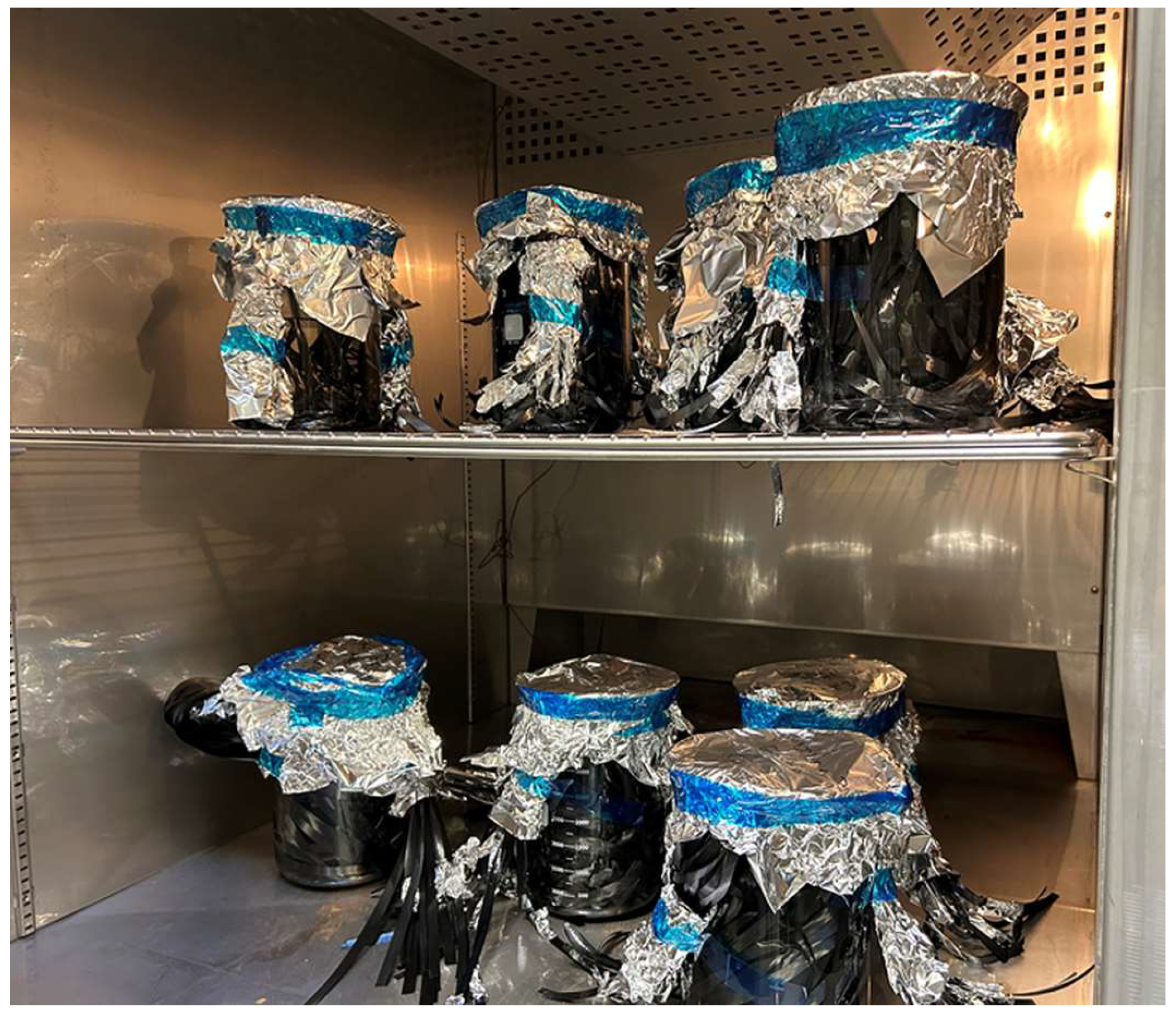
2.2.1. Hydrothermal Aging

Tap water was selected as the aging fluid as it closely resembles the fluids of concern for the applications of interest. It is understood that for future work, the present study can be expanded using deionized water, salt, and aromatic solutions, among others. BFs were conditioned by exposing them to tap water for a maximum of 56 days at 60 °C, 42 days at 71 °C, and 28 days at 82 °C. Similarly, the longest exposure durations for CFs were 70 days at 60 °C, 35 days at 71 °C, and 35 days at 82 °C. The selected temperatures correspond to a broad set of applications in the industry, where the maximum temperature exposure is typically limited by the polymer constituents (such as by their melting temperature). As a general approximation considering Arrhenius’ theory, the reaction rate doubles for every 10 °C increase in temperature, meaning that the material will lose strength in half the time compared to the corresponding lower temperature [19,29]. This is the rationale for the choice of reduced durations of exposure at higher temperatures. Also, the temperatures selected in this study are common for conditioning composites and in-service conditions. Even though it is known that tap water may change from place to place and over the course of the year, the pH of the tap water examined in this study was assumed to be within a narrow range, with an average of 7.9 for all aging conditions. Fibers with a set length of 2.5 m were obtained and placed in a 4 L beaker for conditioning, as illustrated in Figure 1. To promote fiber failure from occurring in the sample gauge length, only the gauge section length of the fibers was immersed. As seen in Figure 1, the beaker was covered with aluminum foil and placed in an oven. Calibrated thermocouples monitored the water temperature in the beakers. Periodically, hot water was carefully added to make up for evaporative losses.

2.2.2. Exposure to Humidity

To explore damage occurring to the fibers in humid conditions, BFs and CFs were also exposed to 90% humidity at 90 °C in an environmental chamber (type SE 1000-3-3, Thermotron, Holland, MI, USA). Since water is present in a vapor state, this setup could be seen as a more realistic condition of elevated temperature exposure to moisture for composites used in real-life applications. BFs were cut to the desired length and mounted onto stainless steel frames, as shown in Figure 2a, and the frames were hung in the oven. Similarly, CFs were cut to the desired length and supported by rods at the top and bottom to prevent the effects of fatigue bending and abrasion due to airflow inside the oven. The fibers were taped together at their non-gauge length portion, as illustrated in Figure 2b. This approach ensures that the fiber gauge length is well exposed and that any other possible contact points are well outside the gauge length.

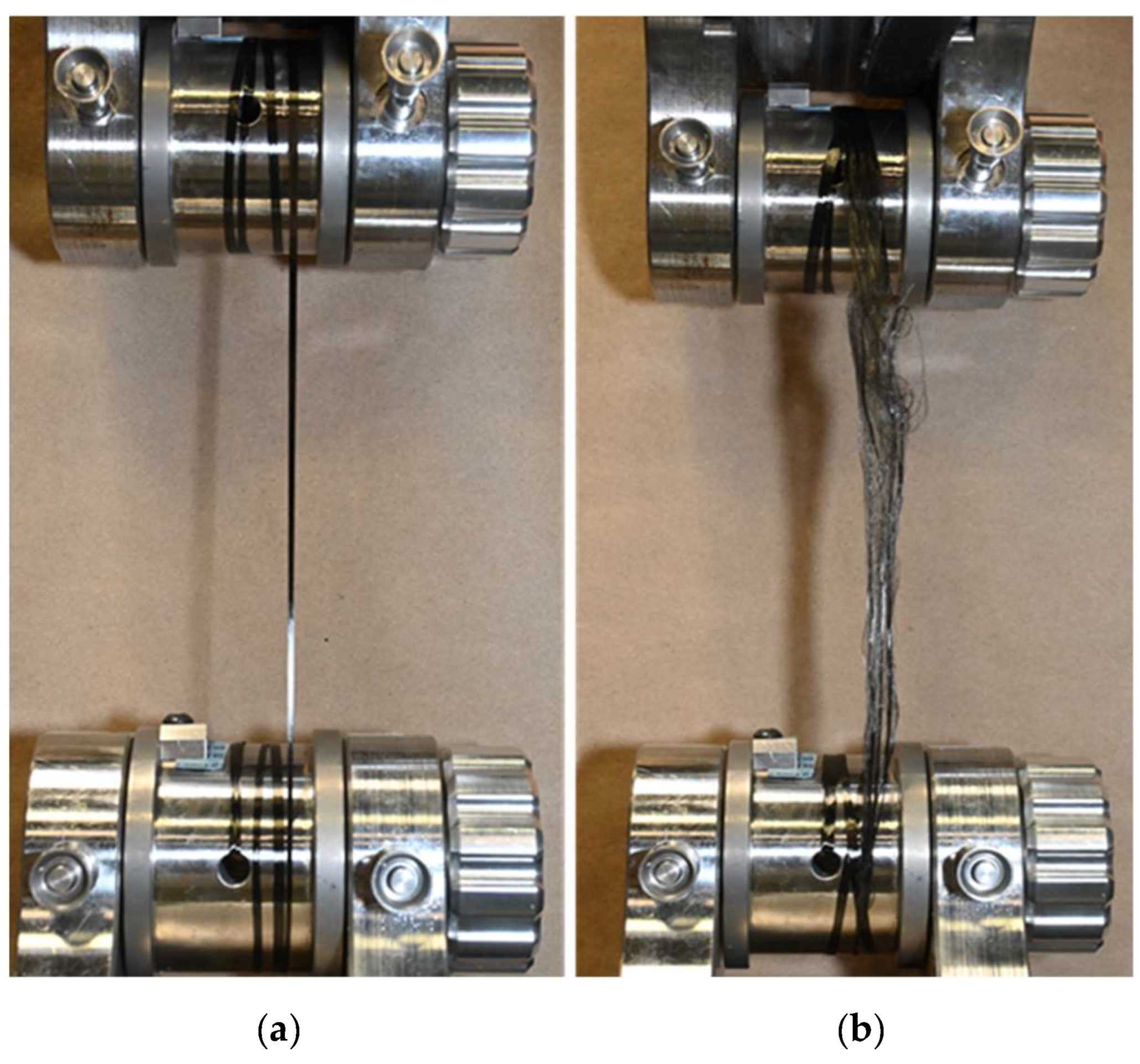
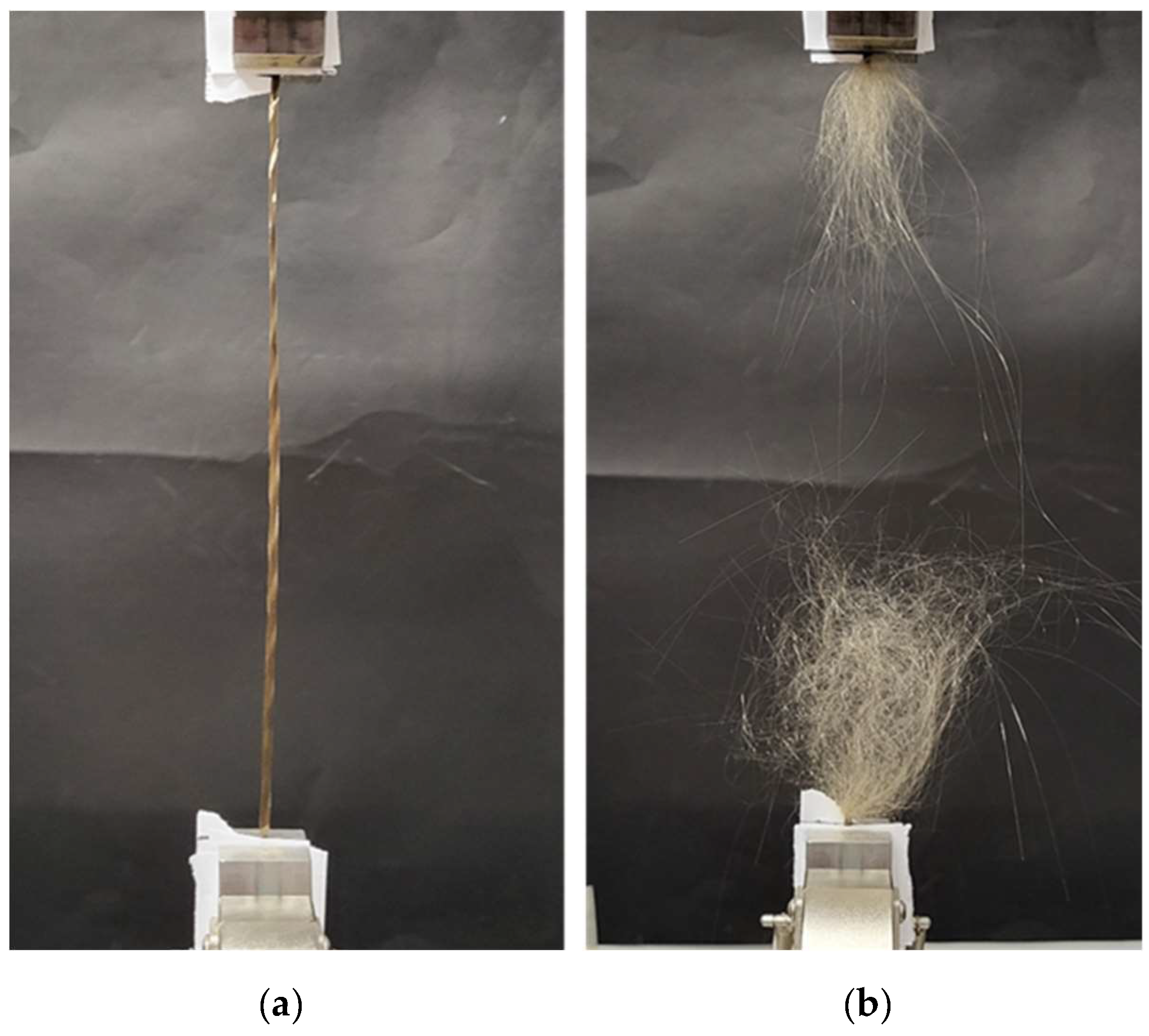
2.2.3. Assessment of Damage Caused by Sample Preparation

During the hydrothermal aging, there is a possibility of damaging fibers due to the bending of samples inside the glass beaker (Figure 1), as this may induce stresses to the fiber, causing a loss in strength. Also, due to air circulation inside the environmental chamber, fibers are agitated, which may lead to fatigue and bending effects that could cause damage. Considering these factors that may cause strength reductions, parallel experiments were performed conditioning the samples but without hydrothermal exposure, and, hence, testing was completed to explore any possible effects causing reductions in properties.

2.3. Tensile Testing

Tensile tests after fiber conditioning were conducted at room temperature (23 °C). At least ten samples were tested in both ‘dry’ and ‘wet’ conditions. In the case of ‘wet’ testing, samples were taken directly from their aging environment and tested. In contrast, samples for ‘dry’ testing were allowed to dry at ambient temperature for at least 24 h before testing. For samples exposed to humidity conditions, testing was performed immediately after removal from the chamber. After tensile testing, the maximum load from the load–displacement curve was used as the breaking load since a significant reduction in the testing load is considered indicative of failure.

2.3.1. Capstan Grips

Capstan grips are often for used for fiber testing and, as shown in Figure 3a, are also employed in this study for CFs. Figure 3b illustrates the typical failure mode experienced by CFs during testing. It is important to note that for BFs a different method was employed, namely, the tabbing method (elaborated in the subsequent subsection). This was necessitated due to the propensity of BFs to fracture during the sample mounting process, as a consequence of their brittleness post-aging, resulting in significant fluctuations in breaking load measurements. The testing procedures were conducted utilizing a universal testing machine (Model 810, MTS Systems, Eden Prairie, MN, USA), featuring a 100 kN load cell. The sample gauge length was approximately 250 mm. A stroke rate of 50.0 mm/min was set. All experiments adhered to the guidelines outlined in the ASTM D2256M-10 standard [30].

2.3.2. Tabbing Method

Figure 4a,b illustrate a BF sample both before and after failure, respectively, utilizing the tabbing method. Given recurrent installation failures encountered with capstan grips, specifically for BFs, the decision was made to adopt the tabbing method for testing these fibers. This method involves determining the desired gauge length and securing the fiber ends with paper tabs, followed by affixing the ends to the grips of the testing machine. The rationale for employing this method stems from its alignment with the ASTM C1557-20 standard [31]. Testing was conducted with a gauge length of approximately 250 mm and a stroke rate of 200.0 mm/min. It is noteworthy that the tabbing approach yielded a more precise representation of modulus and elongation at break values for fibers overall. This indicates its superiority in managing gauge length and twist in the fibers compared to the use of capstan grips. Moreover, the tabbing method effectively mitigates the slack or catenary effect between filaments, leading to a complete failure for the BFs, as depicted in Figure 4b. However, it is important to highlight that if employed for high-strength fibers such as CF, this method may result in sample slippage from the grips.

2.4. Mass Spectroscopy

To investigate the extent and type of chemical elements leaching from the fibers into the aging solution, mass dissolution tests were performed on BFs and CFs. Ten identical fiber strands were selected and placed in plastic tubes, as shown in Figure 5a. A total of 50 mL of deionized water was added to each tube, and the tubes were immersed in a water-filled glass jar and conditioned in the oven, see Figure 5b. Accordingly, this method provides a uniform temperature distribution within the plastic tubes. Parallel experiments were performed at 60 °C and 82 °C for 1 week. Reference tubes without samples were also included along with the actual samples to account for any release of chemical species from the tubes themselves. The concentration of leached ions in water for BFs was measured using an iCAP6300 Duo analyzer inductively coupled with an ICP-OES plasma-optical emission spectrometer (Thermo Fisher Scientific, Waltham, MA, USA). For CFs, the concentration of C and N ions released into the solution was analyzed using a total organic carbon analyzer (TOC-L) with an ASI-L autosampler and a TNM-L total nitrogen unit (both Shimadzu Corporation, Kyoto, Japan).

2.5. Fourier-Transform Infrared Spectroscopy

Both aged and unaged fibers underwent FTIR spectroscopy using a Nicolet Is50 FTIR spectrometer from Thermo Fisher Scientific. This analytical method involves the generation of an infrared spectrum through the absorption of electromagnetic radiation at frequencies corresponding to the vibrational modes of chemical bond groups within a molecule. The samples were analyzed in attenuated total reflectance (ATR) mode, employing a diamond detector. Spectral analysis was conducted over the range of 400–4000 cm−1 with a resolution of 4 cm−1/min.

2.6. Scanning Electron Microscopy

A comparison between the surface morphology of hydrothermally aged and unaged fibers was conducted using a scanning electron microscope (SEM) model S-4800 manufactured by Hitachi in Tokyo, Japan. Prior to imaging, the samples were subjected to gold-coating using a Denton sputter gold coating equipment (Moorestown, NJ, USA) operating at a voltage of 5 kilovolts (kV) and a current of 10 microamperes (µA).

3. Results and Discussion

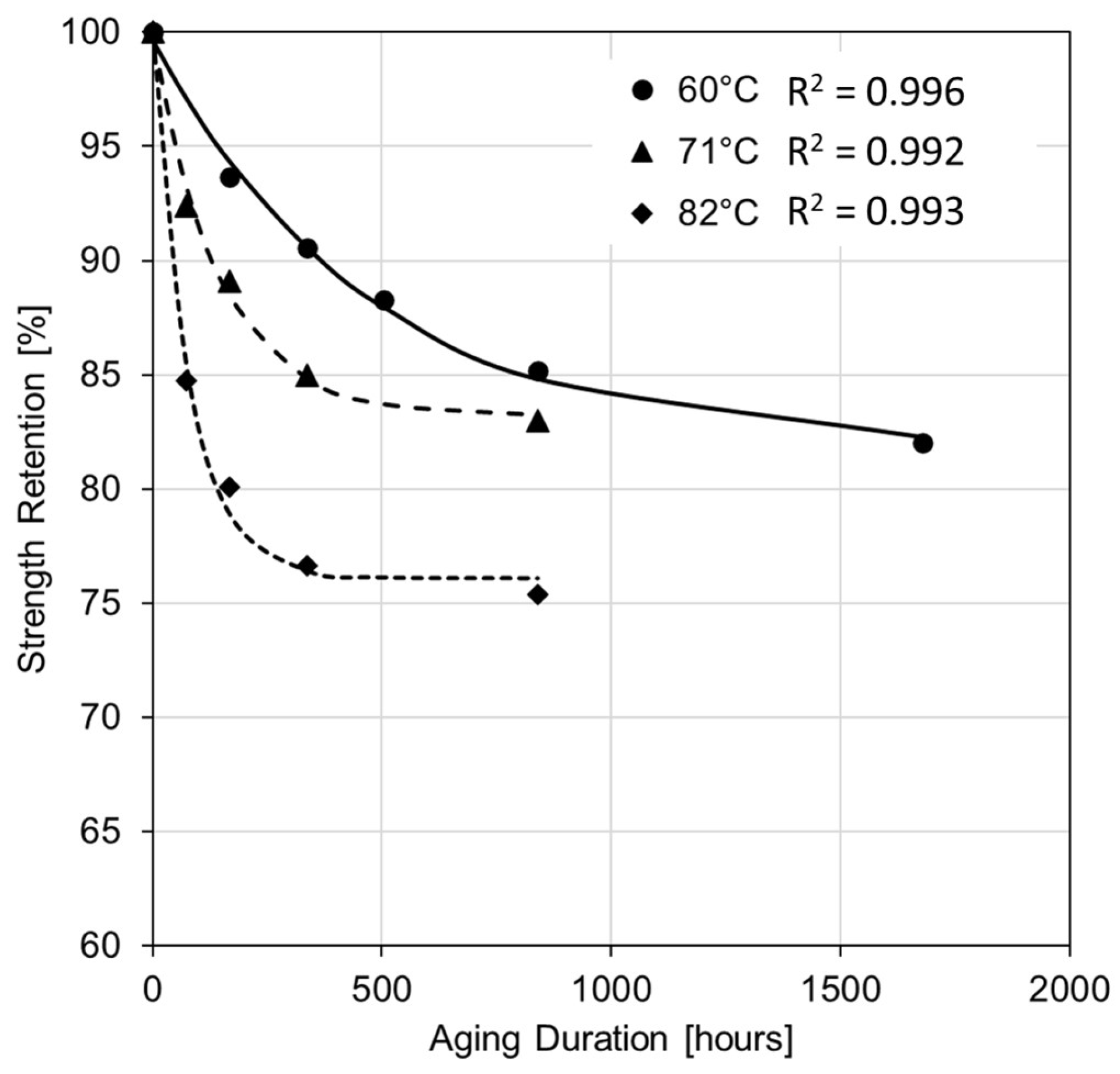
3.1. Variations in Fiber Strength

The variability in fiber strength can be assessed through either breaking tenacity, defined as the ratio of breaking load to fiber linear density, or tensile strength, calculated as the ratio of breaking load to the original cross-sectional area of the sample. The present study seeks to examine strength retention after aging. Consequently, the obtained results for breaking tenacity or tensile strength can be regarded as interchangeable. Notably, BFs subjected to tests aimed at quantifying handling damages exhibited no significant variation in strength. Conversely, CFs showed a slight reduction in strength due to handling, with corresponding values factored into the strength calculation for various test configurations to ensure a conservative approach. As alluded to above, aging conditions in terms of temperatures and durations were selected to induce severe degradation effects, i.e., in the present work, strength reductions of more than 25% are considered severe.

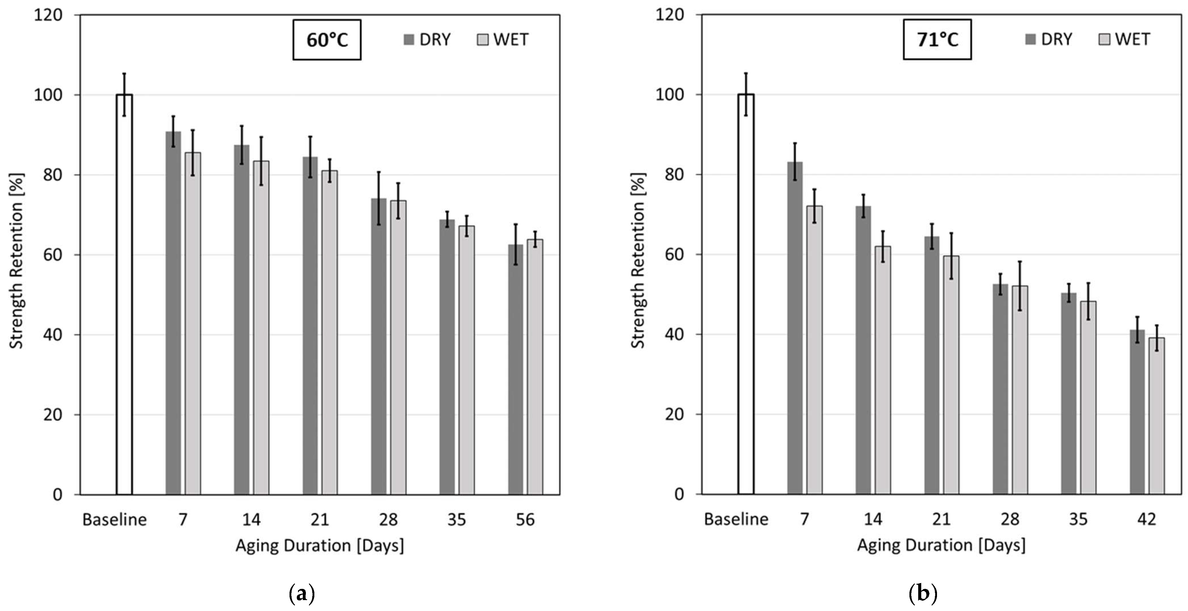
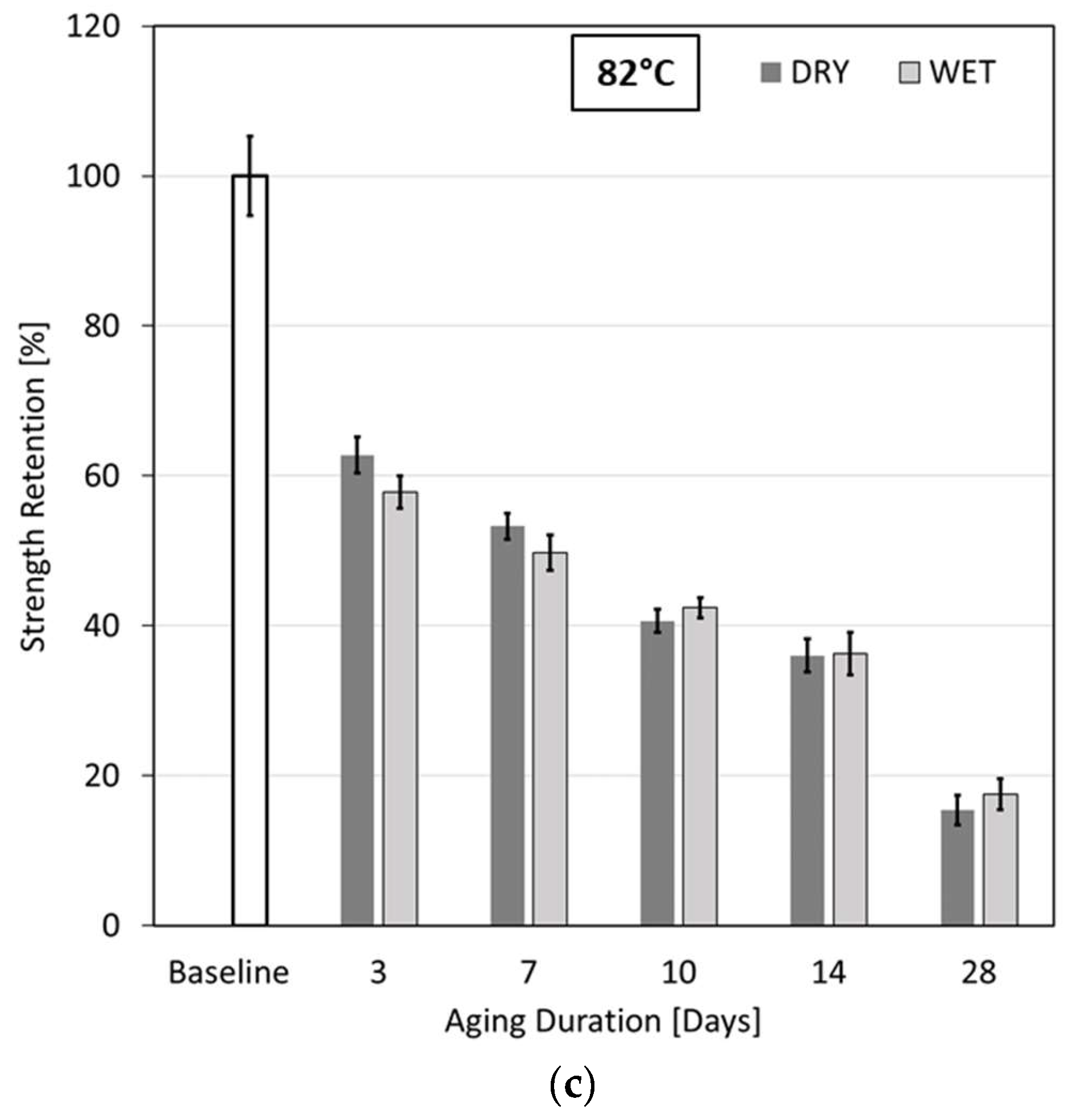
3.1.1. Strength Variations for Basalt Fibers

Figure 6a–c depict the variations in strength retention values for BFs aged at 60 °C, 71 °C, and 82 °C, respectively, for the various test durations, for both ‘wet’ testing and after drying for 24 h. The error bars represent one standard deviation from the mean values. Distinct differences in strength retention values were observed between ‘wet’ and ‘dry’ samples, that is, the ‘wet’ samples exhibited lower mechanical strengths compared to the ‘dry’ samples. It is hypothesized that water between the filaments acts like a lubricant when fibers are tested wet, which largely negates any load sharing between filaments. When tested dry, friction between fibers promotes load sharing between filaments and thus greater fiber strength, which is similar to filaments being embedded in a polymer matrix, but to a much lesser extent. It can be observed that strength retention at 60 °C, shown in Figure 6a, is higher than for 71 °C in Figure 6b, indicating strength retention reduces considerably at elevated temperature conditions. The highest strength reduction occurred for BFs aged at 82 °C for 28 days, see Figure 6c, with a reduction in strength by 82% and 84% when tested in ‘wet’ conditions and after drying, respectively. Strength values of samples aged for 7 days at 60 °C, 71 °C, and 82 °C and tested after drying decreased by 9%, 17%, and 47%, respectively. Therefore, strength values dropped consistently as aging temperatures and durations were increased. Aging at 82 °C was the most severe case for BFs as, for instance, strength dropped by 37% (tested dry) after exposure to water for just 3 days.

3.1.2. Strength Variations for Carbon Fibers

Figure 7a–c show the variations in tensile strength for CFs aged at 60 °C, 71 °C, and 82 °C, respectively, for different durations, again for ‘wet’ and ‘dry’ testing conditions. Again, the error bars represent one standard deviation from the mean values. CFs only exhibited slight variations in strength retention values between ‘wet’ and ‘dry’ samples, that is, wet samples had slightly lower mechanical strengths than dried samples. This difference, albeit smaller than for BFs, was attributed again to reduced friction and load sharing effects between filaments when tested in a wet state.
In contrast to BFs, the retention of mechanical performance of CFs was found to be far superior for all three aging temperatures. Still, as shown in Figure 7a, strength retentions at 60 °C exceed those at 71 °C, depicted in Figure 7b, which bears similarities to BF but to a lesser extent in response to hydrothermal aging conditions. The highest strength reduction occurred for CFs aged at 82 °C for 35 days, see Figure 7c, with a reduction in strength by 26% and 25% when tested in wet conditions and after drying, respectively. In comparison, the percentage reduction for BFs was nearly triple. Similarly, strength values of CF samples aged for 7 days at 60 °C, 71 °C, and 82 °C and tested after drying decreased by 6%, 11%, and 20%, respectively. In general, strength values showed higher reductions with an increase in aging temperatures. There was a notable initial decrease in strength after aging for 7 days, after which strength reduction occurred at a significantly reduced rate. The strength values showed a consistent reduction with respect to the increase in aging durations, except for samples aged for 21 days at 71 °C and 82 °C, which showed a slight increase in strength values with respect to the former aging durations. A similar observation was reported other work, where CFs aged at 60 °C exhibited an increase in strength with an increase in aging durations [20]. This observation was explained by an increase in the number of twists in the fiber samples along the fiber length. As with the current testing methodology, careful attention was paid to eliminate any fiber twist after aging and drying of specimens. To ensure trustable results, some of the tests were repeated, and consistent results were obtained. Similar to BF, but to a much lesser extent, aging at 82 °C was the most severe case for CFs as the strength dropped by 15% (tested dry) after exposure to water for 3 days.

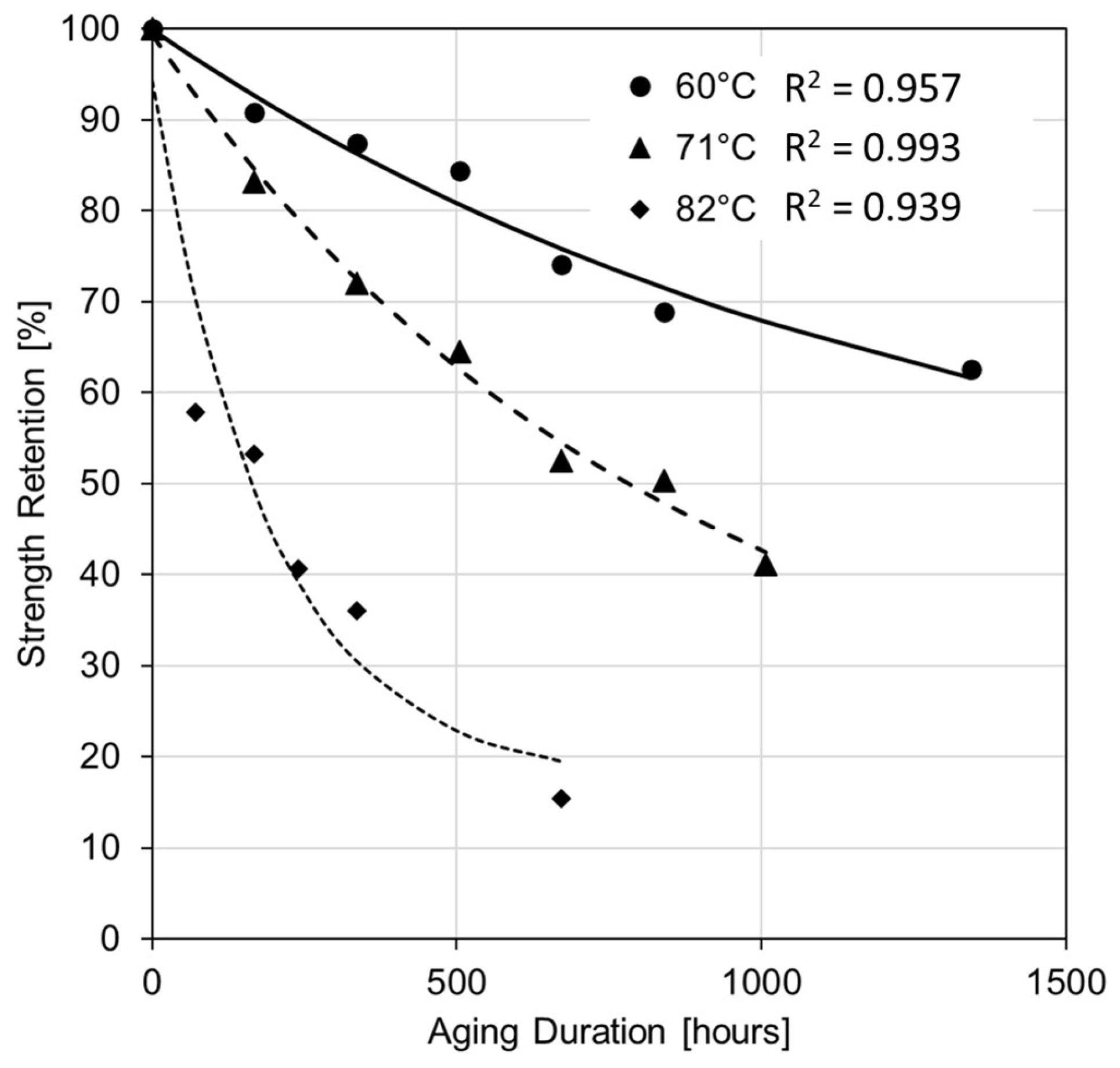
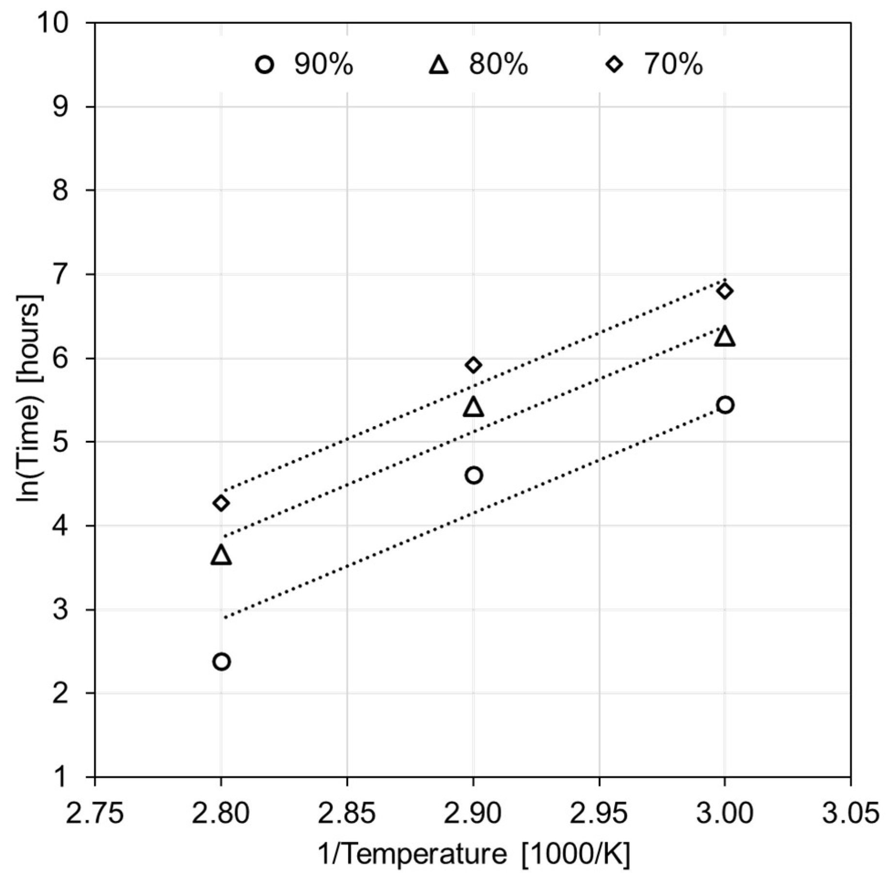
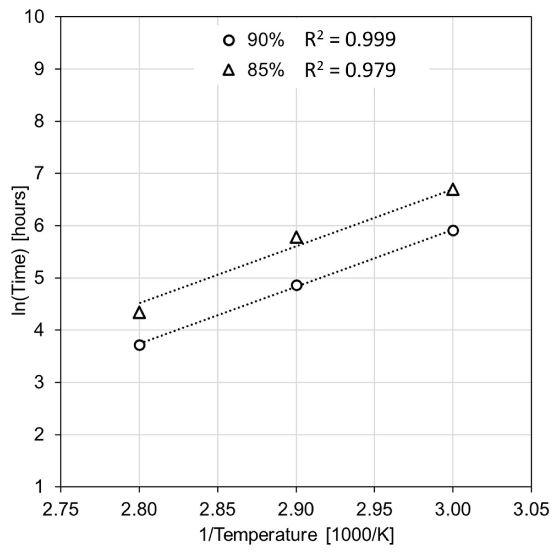
3.2. Prediction of Tensile Strength

3.2.1. Basalt Fibers

The foundation of the prediction methodology relies on the widely recognized Arrhenius relation, as cited in [9]. When temperature is the main accelerating factor in aging for composites, the Arrhenius model is frequently employed to determine service life. For materials below their glass transition temperatures, the Arrhenius model accurately predicts the effects of temperature in accelerated aging experiments. The underlying assumption is that there is a single dominating degradation mechanism that does not change throughout exposure and that the degradation rate accelerates as exposure temperature increases. The analysis incorporated data from fibers assessed in a “dry” environment. The Arrhenius method, also referred to as the predefined life approach, entails the representation of strength retention values through a fitted curve as the initial step. Equation (1) expresses the correlation in this model between the retention of performance and the duration of degradation. This model is commonly utilized to depict retention values at different temperatures for composite materials subjected to hydrothermal aging [29].
Y = A 1 e x p t τ + Y 0 ,
where Y represents the retention in mechanical properties, t is the exposure time, and τ, A1, and Y0 are regression fitting parameters. The values for the regression coefficients are given in Table 1, and the tensile strength retention is shown in Figure 8 as a function of time for the different aging temperatures. It can be observed that the different regression curves exhibit R2 values of 0.939 or greater.
The general form of the Arrhenius model is given by:
k = A · exp E a R ¯ T ,   or   ln k = E a R ¯ T + ln A
where A is a constant associated with the material and aging environment, T is the absolute temperature, R ¯ is the universal gas constant, Ea is the activation energy, and k is the reaction rate constant or degradation rate constant. The reaction rate k in the Arrhenius equation is frequently taken as the time it takes for the material to attain a particular strength loss value [32]. The next step in the analysis involves plotting the logarithm of time to reach the retention values against 1000/T, where T represents temperature in Kelvin. Strength retention levels of 70%, 80%, and 90% were used for this study. The Arrhenius plots for different retention values are displayed in Figure 9. It can be noted that values for 82 °C come to lie significantly below the linear trends that the 60 °C and 71 °C data would delineate. Recalling the tensile test results depicted in Figure 6, BFs aged at 82 °C lost almost 50% of their strength after aging for only 7 days. It is assumed that there was a change in the degradation mechanisms at 82 °C, which violates the fundamental assumptions of the Arrhenius model (i.e., there is a single dominating degradation mechanism that does not change throughout exposure and the degradation rate accelerates as exposure temperature increases [29,33]). With such a deficient model, when extrapolating for lower temperatures, lifetimes would be significantly overpredicted. Hence, as seen in Figure 10, the data points for the 82 °C aging conditions were omitted. In this manner, corrected lifetime prediction plots for the 70%, 80%, and 90% retention values were obtained. Fitted straight lines for the different retention levels are practically parallel, which supports the validity of the accelerated degradation tests and the applicability of the model to forecast the loss of BF tensile strength. The activation energy, 70 kJ, was calculated from the slope of the plot. For example, when interpolating the plot to a temperature of 30 °C, the time to reach retention levels of 70%, 80%, and 90% were predicted from the model as 455 days, 270 days, and 120 days, respectively.
To improve the present analysis, a third temperature lower than 60 °C may be included to better calibrate the model, which may also help delineate and explain deviations from Arrhenius behavior for temperatures near 82 °C and above. However, a test temperature lower than 60 °C would come at the expense of increased test durations. Also, the observed material behavior makes it difficult to employ a time–temperature superposition approach for creating a master curve at a designated reference temperature (e.g., at 60 °C). These findings indicate the challenges and risks of employing the Arrhenius model for service life predictions of composites and materials in general. It is vital to carefully set test conditions and define upper and lower limits for the modelling range.

3.2.2. Carbon Fibers

The analysis steps described in the previous section were followed for CFs and the same modelling approach was used to represent the retention values at different temperatures. The values for regression coefficients are given in Table 2, and the tensile strength retention data are shown in Figure 11 as a function of time for the different temperatures. Retention values for samples aged for 21 days at 71 °C and 82 °C were omitted, as an increase in retention values was observed at those aging periods compared with the former aging periods. Similar to the previous analysis involving BFs, this behavior is considered a violation of the Arrhenius model, as properties are expected to decrease with an increase in aging time. Strength retention levels of 85% and 90% were used for CFs, as these were the levels within the experimentally obtained data for all three temperatures. Retention levels beyond the experimental data are commonly not used for prediction as these could increase the error values associated with the prediction [32]. The Arrhenius plots for different retention values are displayed in Figure 12. The activation energy, 91 kJ, was calculated from the slope of the plot. Interestingly, when interpolating the plot to a temperature of 30 °C, the time to reach a retention level of 90% was predicted from the model as 410 days, more than three times that predicted for BFs. This is a clear indication of a significantly better hydrothermal resistance of CFs over BFs.

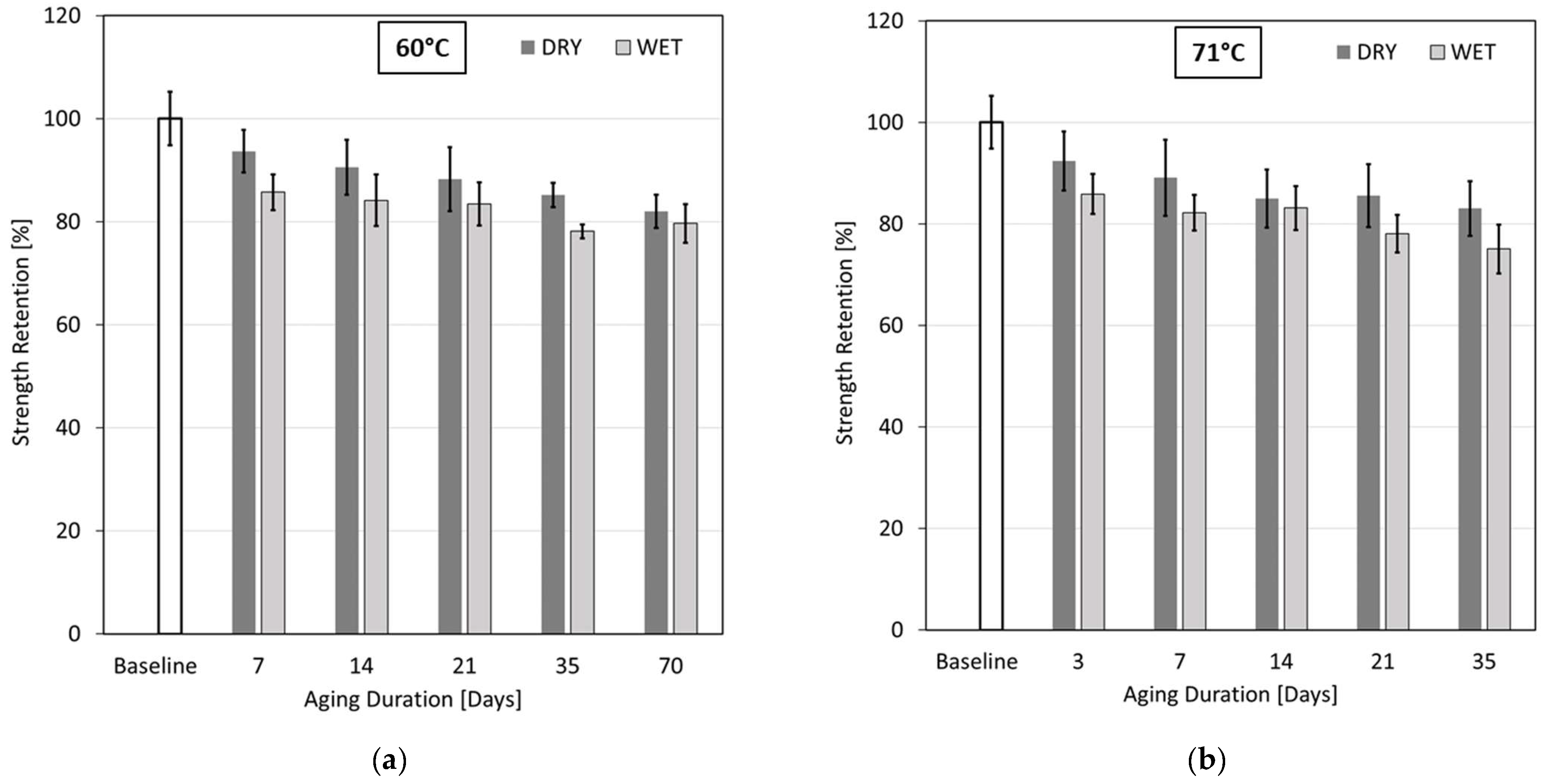
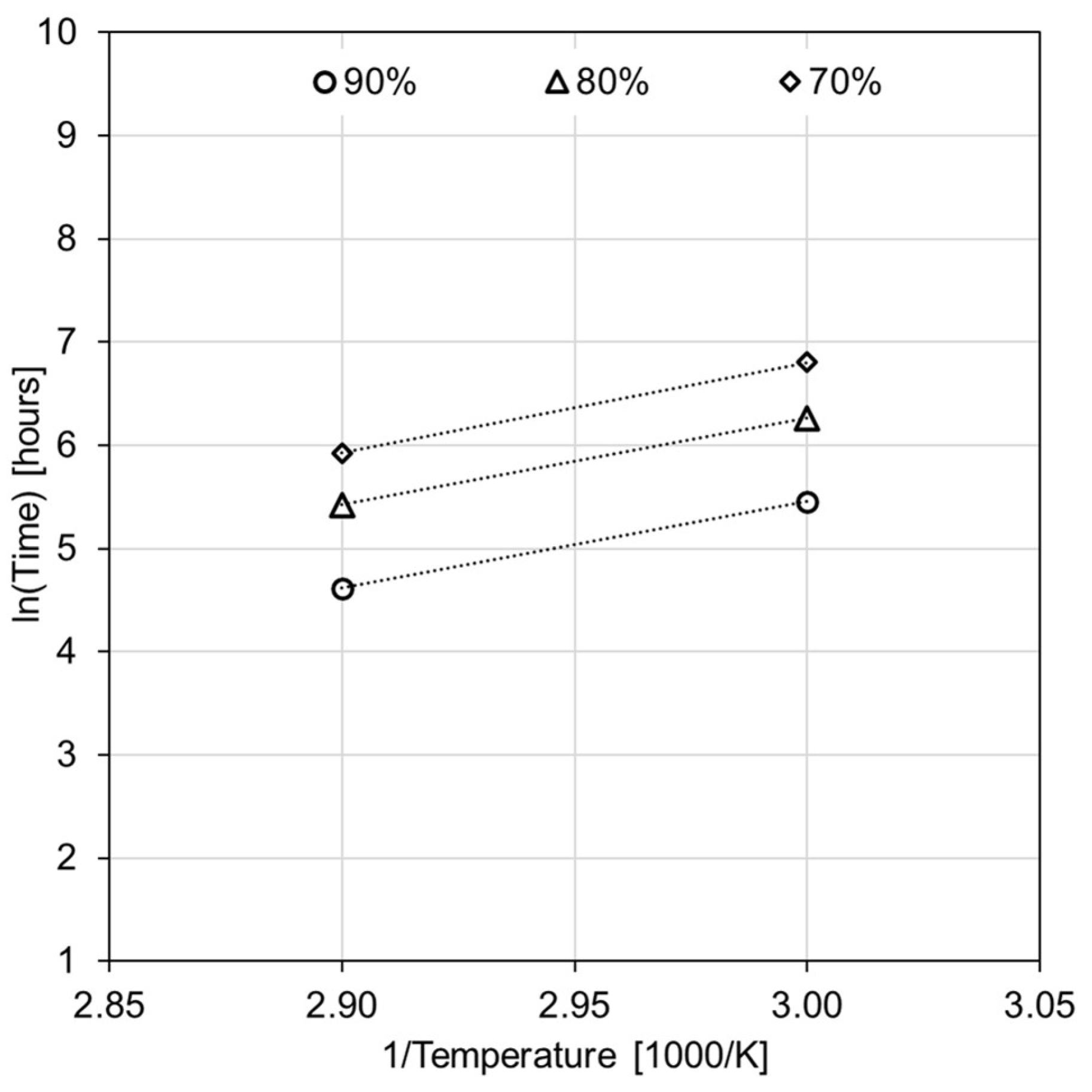
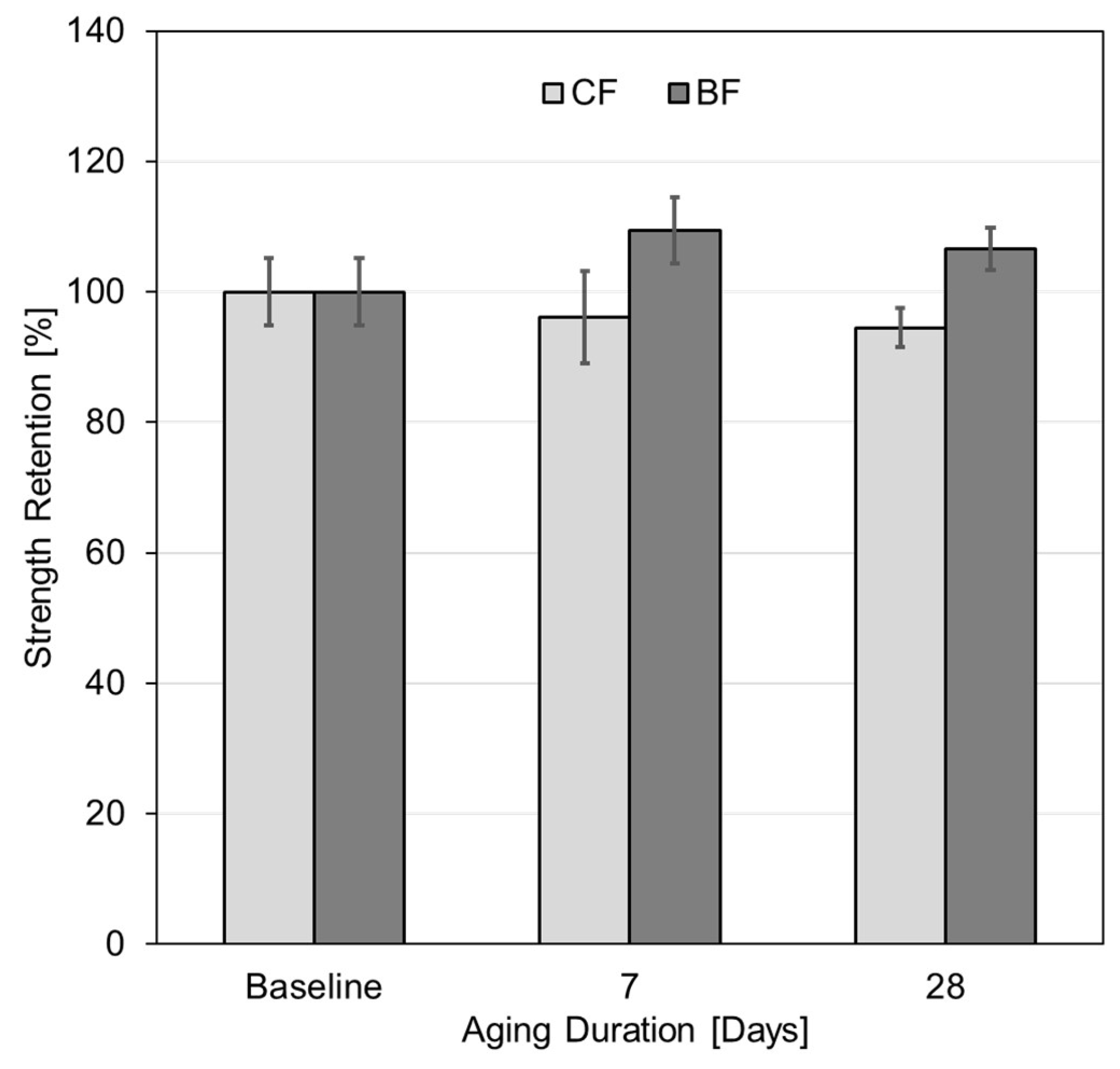
3.3. Variation in Tensile Strength after Exposure to Humidity

Figure 13 shows the variations in strength retention values for BFs and CFs aged at 90 °C and 90% humidity. The fibers were tested immediately after removal from the environmental chamber. As before, the error bars represent one standard deviation from the mean values. CFs exhibited a slight reduction in strength, by 5.5%, after aging for 28 days. In contrast, BFs exhibited a modest increase in strength by 9% after 28 days of exposure.
The results presented in Figure 13 signify that BFs are unaffected by the elevated temperature and humidity conditions, whereas CFs seems to have experienced a slight loss in strength. The reason for this reduction in strength is unknown. There is the possibility of fatigue or stress corrosion damage induced to the fibers due to continuous humid air circulation and agitation of the fibers inside the oven. Also, in humidity aging, the whole length of fibers was exposed, instead of exposing only the gauge length portion as what occurred in hydrothermal aging. Thus, it is possible that the entire fiber was weakened, leading to some premature damage when mounting the samples for testing in the capstan grips. Nevertheless, as one may have expected, the loss in strength is much less severe when compared with that exhibited by the same fibers under hydrothermal aging conditions. This supports the assumption that hydrolysis of the fibers under hydrothermal conditions is responsible for the observed significant strength reductions.

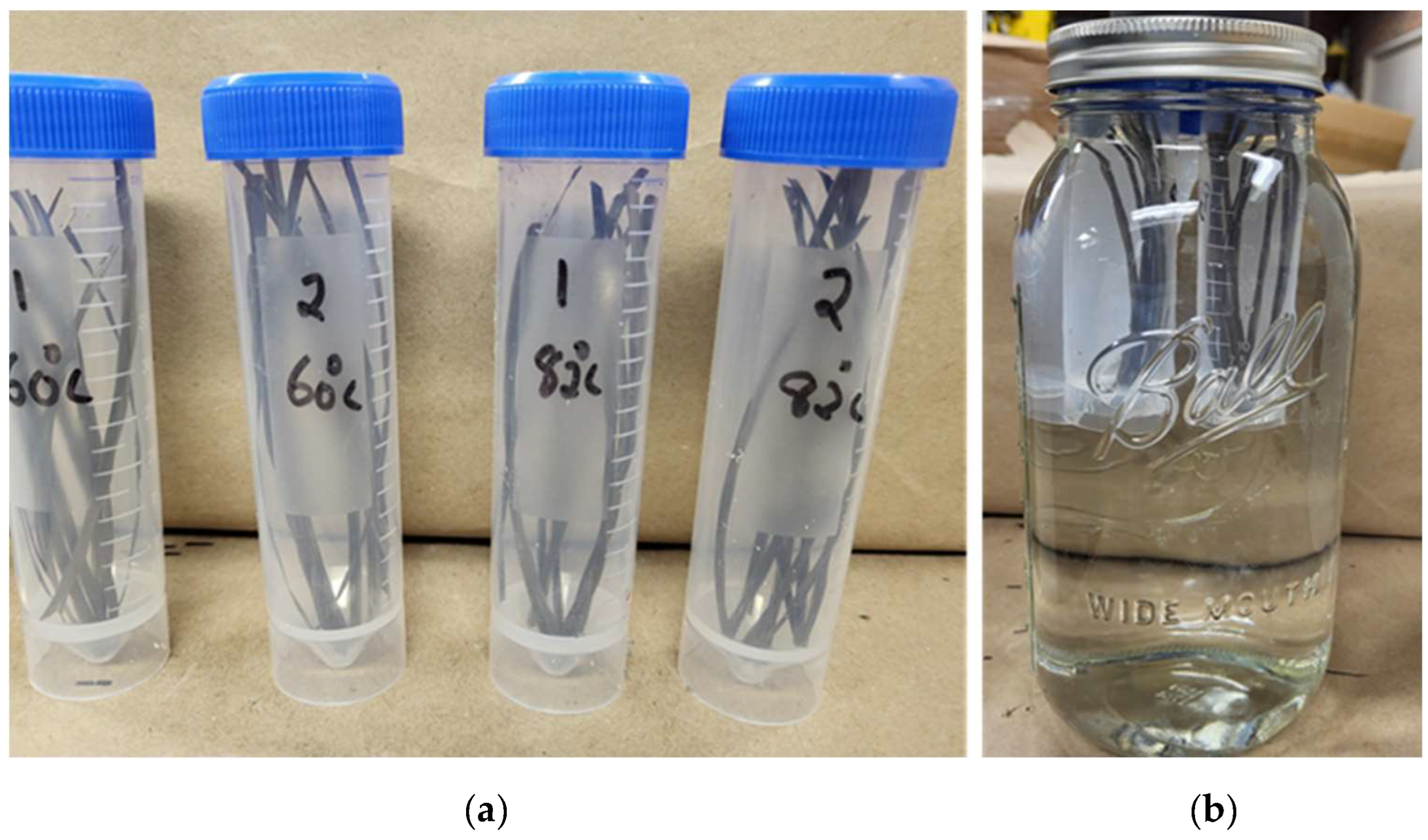
3.4. Mass Dissolution Tests

3.4.1. Basalt Fibers

The elemental analysis reveals that the following chemical elements were released from the BFs: Si, Al, Ca, Na, Mg, K, Fe, and Mn, arranged in the order of decreasing concentration in the solution. The analysis shows an increasing trend in concentration with an increase in temperature, as shown in Table 3. Noticeably, the amount of Si released after conditioning the fibers for 7 days at 82 °C was almost three times higher than that at 60 °C for the same duration. All the other elements showed the same trend with respect to the lower and higher aging temperatures. This significant difference is likely correlated with the observed strength reductions, i.e., strength of BFs aged for 7 days at 60 °C and 82 °C reduced by 9% and 47%, respectively. All released elements are present in the chemical composition of BFs. The hydrolysis of the Si-O-Si framework in BFs, as indicated by Equations (3)–(9), is seen as the primary reason for the observed ion release, especially Si ions [34]. The equations describing this process are the following:
S i O S i + O H   S i O H + S i O  
S i O   + H 2 O   S i O H + O H
S i O K + H 2 O S i O H + O H + K +
S i O A l = + H 2 O S i O H + = A l O H
S i O 2 M g + H 2 O 2 S i O H + 2 O H + M g 2 +
S i O 2 C a + H 2 O 2 S i O H + 2 O H + C a 2 +
S i O N a + H 2 O     S i O H + O H + N a +
From these results, it was concluded that damage occurred to the Si-O-Si framework of BFs due to hydrothermal aging, resulting in the significant release of Si ions and other elements. This finding, therefore, explains observed strength reductions, which will further be corroborated by FTIR and SEM studies.

3.4.2. Carbon Fibers
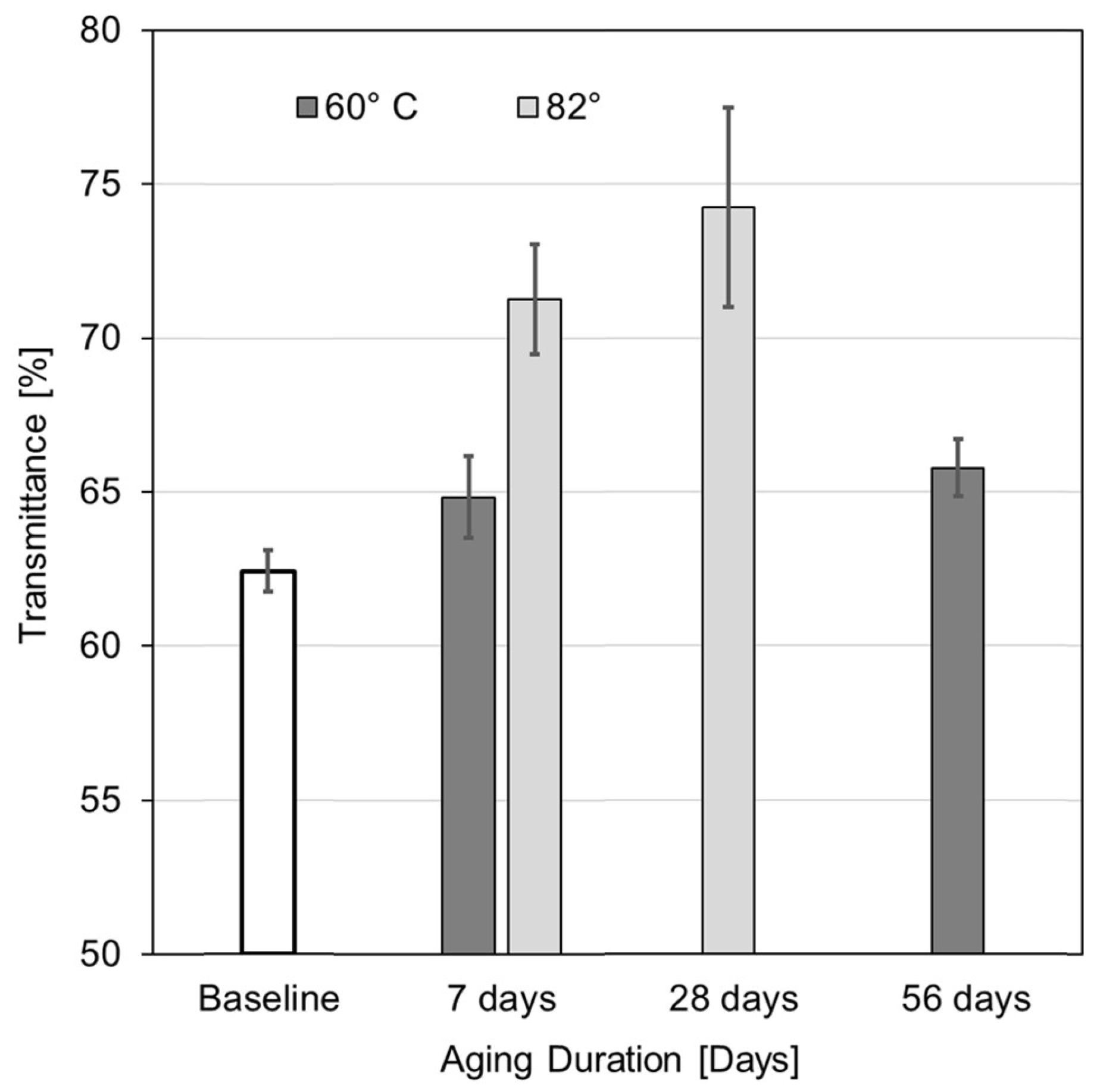
Carbon fibers mainly comprise carbon above 90%, and nitrogen in concentrations ranging from 3% to 7% [35]. Thus, the focus for this analysis was on C and N. Table 4 shows the concentration of C and N released into the solution after aging CFs for 7 days at 60 °C and 82 °C. Differences in the release of these elements may explain strength variations under the given exposure conditions. After conditioning for 7 days at 82 °C, the concentrations of C and N in the solution increased by 14% and 53% when compared with the respective concentrations at 60 °C. It is postulated that the elemental release is due to hydrolysis of the polyacrylonitrile (PAN) network in CFs. However, it is interesting to note that differences in mass concentrations between the two temperature conditions are much less pronounced as compared to BFs, which is indicative of a higher resistance of CF to water compared to BF.

3.5. FTIR Results

For a more comprehensive assessment of the effects of tap water exposure on fibers and their sizing, samples underwent FTIR testing after the drying process. Figure 14 presents the FTIR transmittance spectrum of basalt fiber, which closely mirrors the spectrum of glass fibers. This affirmation indicates the similarity in chemical composition between basalt and glass fibers [36]. The tests were performed using the samples aged at 60 °C and 82 °C with the shortest and longest aging durations. In this manner the effects of increased temperatures and aging durations could be explored. Note that absorption peaks at wavenumbers around 685 cm−1 and 900 cm−1 are attributed to the Si-O bending and Si-O-Si stretching vibrations, respectively [37]. Rising transmittance values imply a reduction in absorption peak intensity. For BFs, the absorption peak intensities were less prominent with an increase in aging duration and temperatures, and fibers aged for 28 days at 82 °C showed the greatest reduction in absorption peak intensity. Similarly, samples aged for 56 days at 60 °C had decreased intensity values, compared with those aged for 7 days at 60 °C and the unaged samples. The reduction in absorption peak intensities corresponds well with the observed strength reductions at these temperatures, where samples aged 28 days at 82 °C had a higher loss in strength when compared to samples aged for 56 days at 60 °C and showed the same behavior with different aging durations within the same temperature. The observed reduction in absorption peak intensities as seen in the FTIR spectrum, therefore, agree with the assumption of damage occurring in the Si-O-Si framework by hydrolysis reactions, as described by Equations (3)–(9).
The above assertion is further explored using Figure 15, which depicts the variation in transmittance values corresponding to the Si-O-Si peaks (occurring at a wavenumber of around 900 cm−1). A steady increase in transmittance values can be observed for rising temperature and aging durations, with higher transmittance implying a reduction in absorption peak intensity. As alluded to above, absorption peak intensity can be attributed to species concentration within the specimen, according to the Beer–Lambert Law [38]. Samples aged for 28 days at 82 °C have the highest increase in their transmittance values (19%), i.e., with the highest absorption peak intensity reduction compared to pristine BFs. Similarly, samples aged for 7 days at 82 °C and 60 °C showed an increase in their transmittance values by 14% and 4%, respectively, indicating a variation in intensity values with increased aging temperatures. This reduction in intensity values is in good agreement with the difference in strength values with increased aging durations and temperatures. Here, the emphasis is given to the reduction across aging durations and within aging temperatures rather than pointing out the absolute values of variation, which may not be true in all cases. The observed intensity reductions provide indication of hydrothermal attack on the Si-O-Si framework, which is a primary building block of BFs, either weakening bonds or breaking bonds leading to the release of ions by the reactions highlighted in the previous section leading to the elemental release. It can, therefore, be presumed that damage caused by hydrothermal aging on the Si-O-Si framework contributes to the reduction in tensile strength with increased aging temperatures and durations.
In contrast to BFs, CFs do not lend themselves to FTIR analysis due to carbon’s capacity to absorb infrared waves across a wide spectrum of frequencies. Consequently, the FTIR data yielded inconclusive results regarding potential chemical processes that might lead to the weakening of CFs. Alternative analytical techniques, such as Raman spectroscopy or X-ray photon spectroscopy, could potentially offer deeper insights into the specific degradation mechanisms occurring during the hydrothermal aging of CFs. However, this study did not explore the use of these approaches.

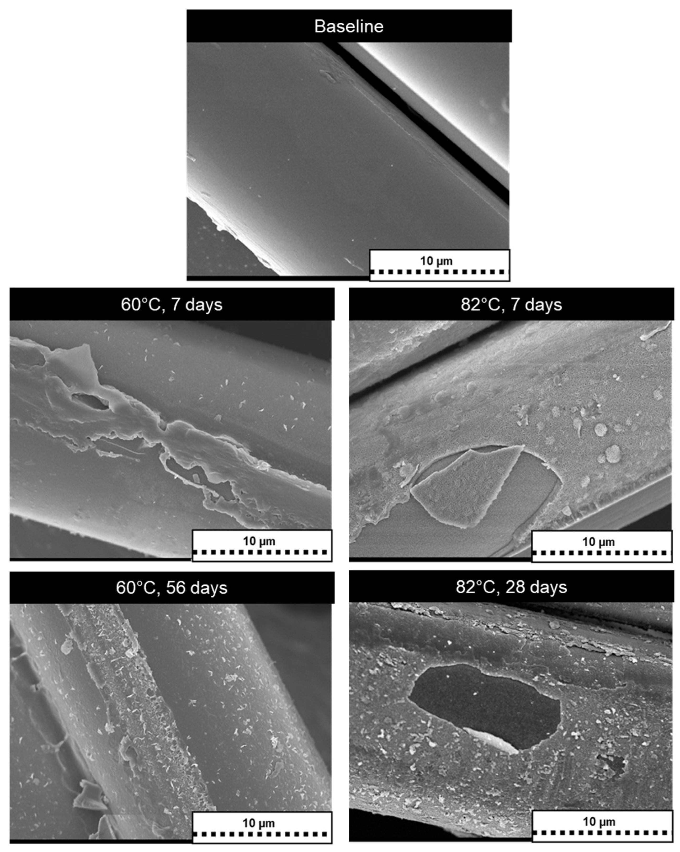
3.6. Morphological Changes

Figure 16 presents SEM images of BF samples, showcasing different surface conditions. The top row illustrates the surface of a pristine filament, while the middle row displays filaments aged at 60 °C and 82 °C for 7 days, and the bottom row exhibits samples aged for 56 days at 60 °C (left) and 28 days at 82 °C (right). A noticeable escalation in filament surface deterioration is evident with increasing aging temperatures and durations. Filaments aged at 60 °C appear to exhibit a relatively lower degree of damage compared to those aged at 82 °C. Surface roughening is observable across all filaments, alongside the formation of deposits, particularly prominent under the 82 °C aging conditions. These deposits are presumed to arise from the dissolution of sizing in tap water or other chemical reactions linked to fiber sizing deterioration. Under the 82 °C condition, patches of material seem to detach from the filaments, indicating heightened brittleness of the filament surface. The extensive surface damage observed in BF filaments may stem from the reactions outlined in preceding sections, including significant sizing damage. In summary, the SEM observations align with the substantial strength reductions observed in BFs at 82 °C compared to 60 °C.
SEM images of CF are shown in Figure 17, where the top row shows the surface of a pristine filament, the middle row shows the surface of filaments aged at 60 °C and 82 °C for 7 days, and in the bottom row, the surfaces of samples aged for 70 days at 60 °C (left) and 35 days at 82 °C (right) are shown. Fibers aged for 35 days at 82 °C exhibit notable deterioration compared to all the other cases. As seen in the images, there is an increase in surface abnormalities with increased aging temperatures and durations. Compared with BFs, the surfaces of carbon fibers exhibit more deposits, especially for the samples aged for longer durations at both 60 °C and 82 °C. These deposits are assumed to have formed because of sizing dissolution in tap water or other chemical reactions related to the sizing degradation of the fibers, or alternatively, due to a deposition of leached elements back on the filament surface.
In general, SEM images reveal a more severe degree of damage in BFs compared to CFs. Recalling the pronounced loss in mechanical properties after aging of BFs compared to CFs, it is postulated that a significant portion of the BF materials was subject to chemical degradation. In contrast, CFs appear to have experienced degradation only on the immediate filament surface and sizing. The postulate of fiber material degradation corresponds with the FTIR findings, which indicate a loss of material and sizing for BFs by various reactions, resulting in a reduced strength after hydrothermal exposure.

4. Conclusions

After hydrothermal aging, BFs and CFs exhibited a notable loss in strength, with samples tested wet showing the highest reductions. Among the reinforcements, CF was most durable, with a maximum drop in strength of 26% for samples aged 35 days at 82 °C. The percentage reduction was substantially larger, nearly triple, for BF. For 90% humidity exposure, BF did not experience any loss in strength at 90 °C, whereas CF experienced a reduction in strength by 5.5% after 28 days of exposure. Changes in concentration values of chemical elements released during hydrothermal aging for both CF and BF explained the higher reductions in strength occurring at higher aging temperatures. The intensity reductions in FTIR spectra for BF support the conclusion that chemical reactions led to substantial strength loss in BF. The mass dissolution and FTIR results indicate an attack by water on the chemical structure of the fibers, coupled with a loss of sizing, caused a reduction in tensile strength when exposed to hydrothermal conditions. SEM imaging revealed surface damage to the filament and their sizing, which supports the claim that the tested fiber materials are vulnerable to degradation when exposed to water at elevated temperatures.
Another notable finding of this study is that changes in fiber strengths demonstrate Arrhenius-based degradation behavior, within limits, as there is a corresponding increase in strength loss occurring with an increase in temperature and aging durations. Strength retention plots were established for both fibers. For BF, omitting data points associated with 82 °C yielded a suitable fit to the Arrhenius model. These findings suggest the need for additional test temperatures below 60 °C for calibrating the Arrhenius model while also exposing the limitation of the modeling approach for BF at the high temperature condition. For CF, the strength retention values agreed with the Arrhenius model. Activation energies calculated using the Arrhenius model were 91 kJ and 70 kJ for CF and BF, respectively. As an example, employing the developed models, the predicted times for a 90% retention level at 30 °C are 120 and 410 days for BF and CF, respectively. The general modelling strategy may serve as a step toward developing a composite aging multiscale modeling paradigm involving reinforcement properties. Such an approach would be valuable to translate reductions in reinforcement strength to an actual composite structure, which could result in a significant decrease in cost and lead time required for these durability studies.

Author Contributions

Conceptualization, J.S., J.P.M. and H.N.; methodology, software, validation, J.S., H.N. and J.P.M.; formal analysis, investigation, data curation, J.S.; resources, H.N. and P.M.; writing—original draft preparation, J.S.; writing—review and editing, J.S., J.P.M. and P.M.; visualization, J.S. and P.M.; supervision, J.P.M., H.N. and P.M.; project administration, H.N. and P.M.; funding acquisition, P.M. All authors have read and agreed to the published version of the manuscript.

Funding

This research and the APC was jointly funded by Shawcor Ltd. and the Natural Sciences and Engineering Research Council of Canada through an Alliance Grant with grant number ALLRP 568487-21.

Data Availability Statement

The original contributions presented in the study are included in the article, further inquiries can be directed to the corresponding author.

Acknowledgments

The authors would like to gratefully acknowledge the support by NanoFAB at the University of Alberta for providing the facility for conducting the FTIR and SEM tests.

Conflicts of Interest

Author Hadi Nazaripoor was employed by the company Flexpipe, Mattr Infrastructure Technologies. The remaining authors declare that the research was conducted in the absence of any commercial or financial relationships that could be construed as a potential conflict of interest.

References

  1. Krauklis, A.E. Modular Paradigm for Composites: Modeling Hydrothermal Degradation of Glass Fibers. Fibers 2021, 9, 83. [Google Scholar] [CrossRef]
  2. Krauklis, A.E. Environmental Aging of Constituent Materials in Fiber Reinforced Polymer Composites. Ph.D. Thesis, NTNU, Trondheim, Norway, July 2019. [Google Scholar]
  3. Feih, S.; Wei, J.; Kingshott, P.; Sorensen, B. The influence of fibre sizing on the strength and fracture toughness of glass fibre composites. Compos. Part A Appl. Sci. Manuf. 2005, 36, 245–255. [Google Scholar] [CrossRef]
  4. Cousin, P.; Hassan, M.; Vijay, P.; Robert, M.; Benmokrane, B. Chemical resistance of carbon, basalt, and glass fibers used in FRP reinforcing bars. J. Compos. Mater. 2019, 53, 3651–3670. [Google Scholar] [CrossRef]
  5. Wei, B.; Cao, H.; Song, S. Tensile behavior contrast of basalt and glass fibers after chemical treatment. Mater. Des. 2010, 31, 4244–4250. [Google Scholar] [CrossRef]
  6. Sim, J.; Park, C. Characteristics of basalt fiber as a strengthening material for concrete structures. Compos. B Eng. 2005, 36, 504–512. [Google Scholar] [CrossRef]
  7. Grabovac, I.; Whittaker, D. Application of bonded composites in the repair of ships structures—A 15-year service experience. Compos. Part A Appl. Sci. Manuf. 2009, 40, 1381–1398. [Google Scholar] [CrossRef]
  8. Robert, M.; Roy, R.; Benmokrane, B. Environmental effects on glass fiber reinforced polypropylene thermoplastic composite laminate for structural applications. Polym. Compos. 2010, 31, 604–611. [Google Scholar] [CrossRef]
  9. Kuram, E. Thermal and water ageing effect on mechanical, rheological and morphological properties of glass-fibre-reinforced poly (oxymethylene) composite. Proc. Inst. Mech. Eng. E J. Process Mech. Eng. 2019, 233, 211–224. [Google Scholar] [CrossRef]
  10. Borges, C.; Akhavan-Safar, A.; Marques, E.; Carbas, R.; Ueffing, C.; Weißgraeber, P.; da Silva, L. Effect of water ingress on the mechanical and chemical properties of polybutylene terephthalate reinforced with glass fibers. Materials 2021, 14, 1261. [Google Scholar] [CrossRef]
  11. Messana, A.; Airale, A.; Ferraris, A.; Sisca, L.; Carello, M. Correlation between thermo-mechanical properties and chemical composition of aged thermoplastic and thermosetting fiber reinforced plastic materials. Mater. Werkst. 2017, 48, 447–455. [Google Scholar] [CrossRef]
  12. Silva, M.; da Fonseca, B.; Biscaia, H. On estimates of durability of FRP based on accelerated tests. Compos. Struct. 2014, 116, 377–387. [Google Scholar] [CrossRef]
  13. Krauklis, A.E.; Ggani, A.; Echtermeyer, A. Long-term hydrolytic degradation of the sizing-rich composite interphase. Coatings 2019, 9, 263. [Google Scholar] [CrossRef]
  14. Krauklis, A.E.; Karl, C.; Gagani, A.; Jørgensen, J. Composite material recycling technology—State-of-the-art and sustainable development for the 2020s. J. Compos. Sci. 2021, 5, 28. [Google Scholar] [CrossRef]
  15. Kasper, A. Recycling composites: FAQs. Reinf. Plast. 2008, 52, 39. [Google Scholar] [CrossRef]
  16. Fang, M.; Zhang, N.; Huang, M.; Lu, B.; Lamnawar, K.; Liu, C.; Shen, C. Effects of hydrothermal aging of carbon fiber reinforced polycarbonate composites on mechanical performance and sand erosion resistance. Polymers 2020, 12, 2453. [Google Scholar] [CrossRef]
  17. Dong, S.; Zhou, P.; Guo, R.; Li, C.; Xian, G. Durability study of glass fiber reinforced polypropylene sheet under simulated seawater sea sand concrete environment. J. Mater. Res. Technol. 2022, 20, 1079–1092. [Google Scholar] [CrossRef]
  18. Krauklis, A.E.; Gagani, A.; Vegere, K.; Kalnina, I.; Klavins, M.; Echtermeyer, A. Dissolution Kinetics of R-Glass Fibers: Influence of Water Acidity, Temperature, and Stress Corrosion. Fibers 2019, 7, 22. [Google Scholar] [CrossRef]
  19. Davalos, J.; Chen, Y.; Ray, I. Long-term durability prediction models for GFRP bars in concrete environment. J. Compos. Mater. 2012, 46, 1899–1914. [Google Scholar] [CrossRef]
  20. Kececi, E.; Asmatulu, R. Effects of moisture ingressions on mechanical properties of honeycomb-structured fiber composite for aerospace applications. Int. J. Adv. Manuf. Technol. 2017, 88, 459–470. [Google Scholar] [CrossRef]
  21. Yang, B.; Zhang, J.; Zhou, L.; Lu, M.; Liang, W.; Wang, Z. Effect of fiber surface modification on water absorption and hydrothermal aging behaviors of GF/pCBT composites. Compos. B Eng. 2015, 82, 84–91. [Google Scholar] [CrossRef]
  22. Zhang, Y.; Mi, C. Improved hydrothermal aging performance of glass fiber-reinforced polymer composites via silica nanoparticle coating. J. Appl. Polym. Sci. 2020, 137, 19. [Google Scholar] [CrossRef]
  23. Jiang, D.; Xing, L.; Liu, L.; Sun, S.; Zhang, Q.; Wu, Z.; Yan, X.; Guo, J.; Huang, Y.; Guo, Z. Enhanced mechanical properties and anti-hydrothermal ageing behaviors of unsaturated polyester composites by carbon fibers interfaced with POSS. Compos. Sci. Technol. 2015, 117, 168–175. [Google Scholar] [CrossRef]
  24. Echtermeyer, A.; Krauklis, A.; Gagani, A.; Sæter, E. Zero Stress Aging of Glass and Carbon Fibers in Water and Oil—Strength Reduction Explained by Dissolution Kinetics. Fibers 2019, 7, 107. [Google Scholar] [CrossRef]
  25. Sunny, J.; Palacios Moreno, J.; Nazaripoor, H.; Mertiny, P. Accelerated Zero-Stress Hydrothermal Aging of Dry E-Glass Fibers and Service Life Prediction Using Arrhenius Model. Fibers 2023, 11, 70. [Google Scholar] [CrossRef]
  26. Sunny, J.; Palacios Moreno, J.; Nazaripoor, H.; Mertiny, P. Accelerated zero stress aging of glass, basalt and carbon fibers-strength reduction explained by chemical and morphological analysis. In Proceedings of the 2023 Canadian Society for Mechanical Engineering International Conference, Sherbrooke, QC, Canada, 28–31 May 2023. [Google Scholar]
  27. Hexcel Carbon Fiber Technical Datasheet. Available online: https://www.hexcel.com/user_area/content_media/raw/IM2A_HexTow_DataSheet.pdf (accessed on 5 September 2022).
  28. Basalt Fiber Technical Data Sheet. Available online: https://www.mafic.com/product-lines (accessed on 5 September 2022).
  29. Zhu, J.; Deng, Y.; Chen, P.; Wang, G.; Min, H.; Fang, W. Prediction of long-term tensile properties of glass fiber reinforced composites under acid-base and salt environments. Polymers 2022, 14, 3031. [Google Scholar] [CrossRef] [PubMed]
  30. ASTM D2256M-10; Standard Test Method for Tensile Properties of Yarns by the Single-Strand Method. ASTM International: West Conshohocken, PA, USA, 2015.
  31. ASTM D2343-17; Standard Test Method for Tensile Properties of Glass Fiber Strands, Yarns, and Rovings Used in Reinforced Plastics. ASTM International: West Conshohocken, PA, USA, 2009.
  32. ISO 11346; Rubber, Vulcanized or Thermoplastic Estimation of Life Time and Maximum Temperature of Use. International Organization for Standardization: Geneva, Switzerland, 2014.
  33. Starkova, O.; Gagani, A.; Karl, C.; Rocha, I.; Burlakovs, J.; Krauklis, A. Modelling of environmental ageing of polymers and polymer composites-durability prediction metholds. Polymers 2022, 14, 907. [Google Scholar] [CrossRef] [PubMed]
  34. Krauklis, A.E.; Echtermeyer, A. Long-term dissolution of glass fibers in water described by dissolving cylinder zero-order kinetic model: Mass loss and radius reduction. Open Chem. 2018, 16, 1189–1199. [Google Scholar] [CrossRef]
  35. Pusch, J.; Wohlmann, B. Carbon fibers. In Inorganic and Composite Fibers: Production, Properties, and Applications; Woodhead Publishing: Oxford, UK, 2018; pp. 31–51. [Google Scholar] [CrossRef]
  36. Liu, J.; Chen, M.; Yang, J.; Wu, Z. Study on mechanical properties of basalt fibers superior to E-glass fibers. J. Nat. Fibers 2022, 19, 882–894. [Google Scholar] [CrossRef]
  37. Rani, M.; Choudhary, P.; Krishnan, V.; Zafar, S. Development of sustainable microwave-based approach to recover glass fibers for wind turbine blades composite waste. Resour. Conserv. Recycl. 2022, 179, 106107. [Google Scholar] [CrossRef]
  38. Abidi, N. FTIR Microspectroscopy: Selected Emergency Applications; Springer International Publishing: Cham, Switzerland, 2021; pp. 1–134. [Google Scholar]
Figure 1. Aging of fiber samples inside an oven.
Fibers 12 00058 g001
Figure 2. (a) Basalt fibers mounted on frames, and (b) carbon fibers, inside the humidity chamber.
Fibers 12 00058 g002
Figure 3. Mechanical testing using capstan grips for carbon fibers: (a) pre-test and (b) post-failure.
Fibers 12 00058 g003
Figure 4. Mechanical testing of basalt fibers using paper tabs: (a) pre-test and (b) post-failure.
Fibers 12 00058 g004
Figure 5. (a) Samples inside plastic tubes, (b) jars used for conditioning fibers.
Fibers 12 00058 g005
Figure 6. Variations in tensile strength for BFs aged at (a) 60 °C, (b) 71 °C, (c) 82 °C.
Fibers 12 00058 g006aFibers 12 00058 g006b
Figure 7. Variations in tensile strength for CFs aged at (a) 60 °C, (b) 71 °C, (c) 82 °C.
Fibers 12 00058 g007aFibers 12 00058 g007b
Figure 8. Plot for strength retention with fitted curves for BFs.
Fibers 12 00058 g008
Figure 9. Arrhenius plot for different strength retention levels of BFs. Trendlines are merely included to guide the eye.
Fibers 12 00058 g009
Figure 10. Corrected Arrhenius plot with different strength retention levels for BFs.
Fibers 12 00058 g010
Figure 11. Plot for strength retention with fitted curves for CFs.
Fibers 12 00058 g011
Figure 12. Arrhenius plot with different strength retention levels for CFs.
Fibers 12 00058 g012
Figure 13. Variations in tensile strength for fibers exposed to 90 °C and 90% humidity.
Fibers 12 00058 g013
Figure 14. FTIR spectra of aged and unaged BFs.
Fibers 12 00058 g014
Figure 15. Variation in transmittance values for aged and unaged BFs.
Fibers 12 00058 g015
Figure 16. SEM images showing BF surfaces before and after aging. Baseline of pristine fiber (top row); aged at 60 °C and 82 °C for 7 days (middle row); and for 56 days at 60 °C and 28 days at 82 °C (bottom row).
Fibers 12 00058 g016
Figure 17. SEM images showing CF surfaces before and after aging. Baseline of pristine fiber (top row); aged at 60 °C and 82 °C for 7 days (middle row); and for 70 days at 60 °C and 35 days at 82 °C (bottom row).
Fibers 12 00058 g017
Table 1. Regression coefficients for strength retention curves for BFs.
Aging Temperature [°C]A1 [N]τ [hour]Y0 [N] E a / R ¯ [K]
6058.651268.741.268410
7181.11837.518.168410
8277.20190.917.258410
Table 2. Regression coefficients for strength retention curves for CFs.
Aging Temperature [°C]A1 [N]τ [hour]Y0 [N] E a / R ¯ [K]
6017.89477.1881.7610,940
7116.51146.7583.1810,940
8223.7278.3676.1110,940
Table 3. Mass of chemical elements released from BFs aged in water at 60 °C and 82 °C for 7 days.
ElementSiCaAlNaMgK
Concentration at 60 °C [mg/L]3.150.380.70.510.230.21
Concentration at 82 °C [mg/L]12.491.544.121.361.160.67
Table 4. Mass of chemical elements released from CFs aged in water at 60 °C and 82 °C for 7 days.
ElementCN
Concentration at 60 °C [mg/L]30.520.27
Concentration at 82 °C [mg/L]34.790.42
Disclaimer/Publisher’s Note: The statements, opinions and data contained in all publications are solely those of the individual author(s) and contributor(s) and not of MDPI and/or the editor(s). MDPI and/or the editor(s) disclaim responsibility for any injury to people or property resulting from any ideas, methods, instructions or products referred to in the content.

