

The Effect of Carbon Nanotubes and Carbon Microfibers on the Piezoresistive and Mechanical Properties of Mortar
 ,
,  ,
, 
Abstract
:1. Introduction
2. Materials and Methods
2.1. Materials
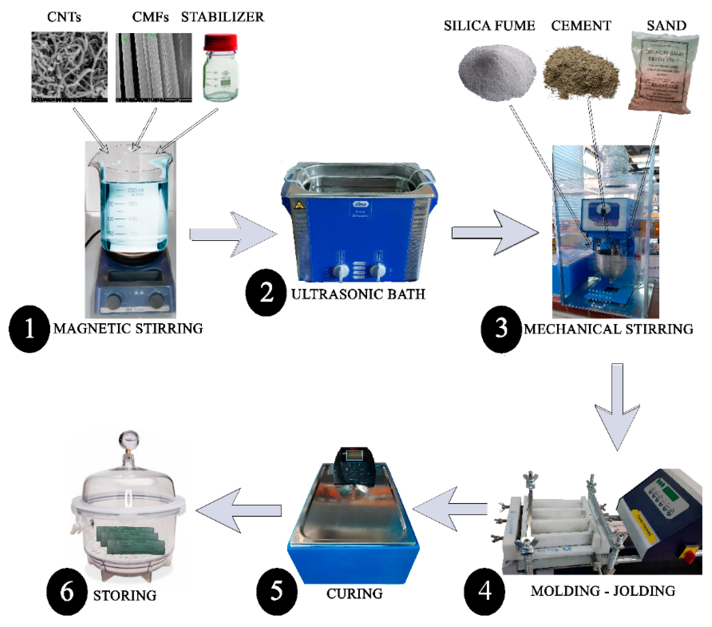
2.2. Synthesis of Reinforced Mortars
2.3. Characterization
3. Results
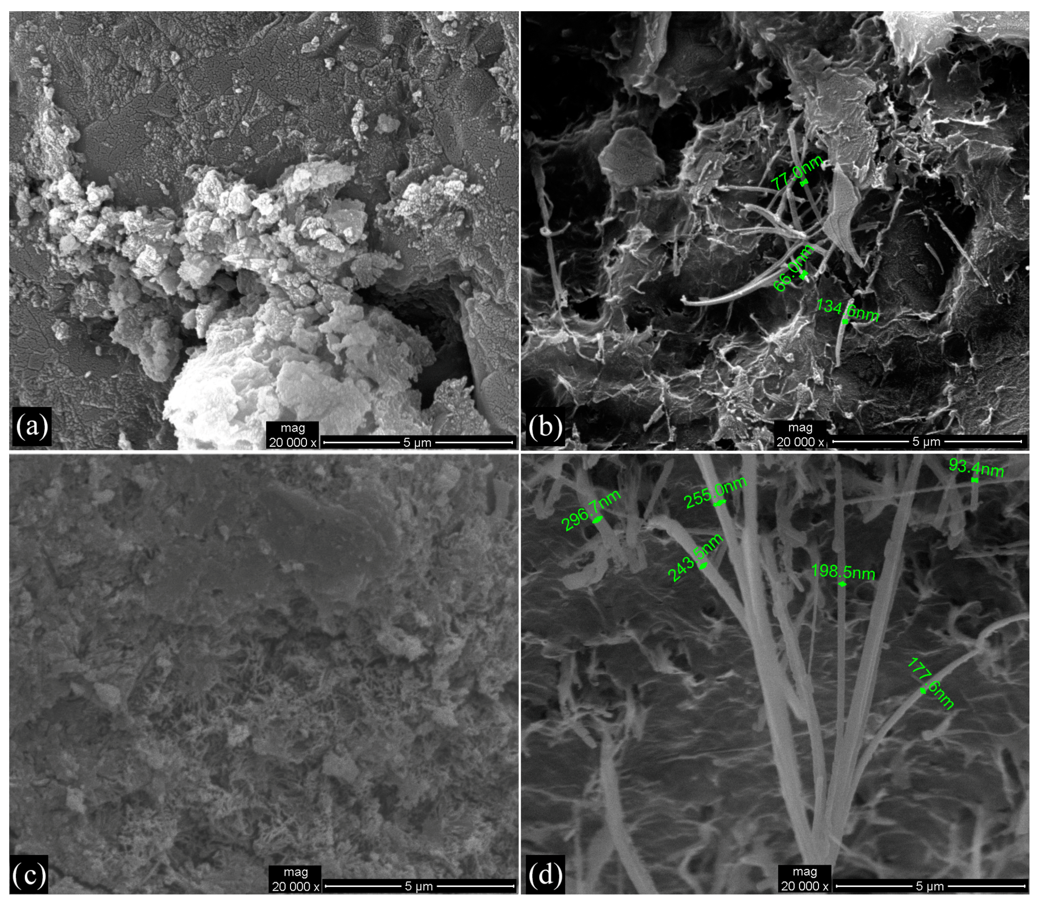
3.1. Morphological and Structural Characterization
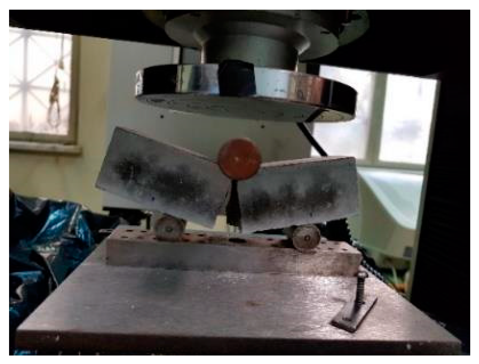
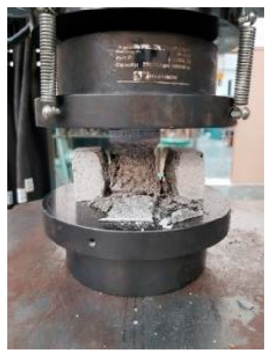
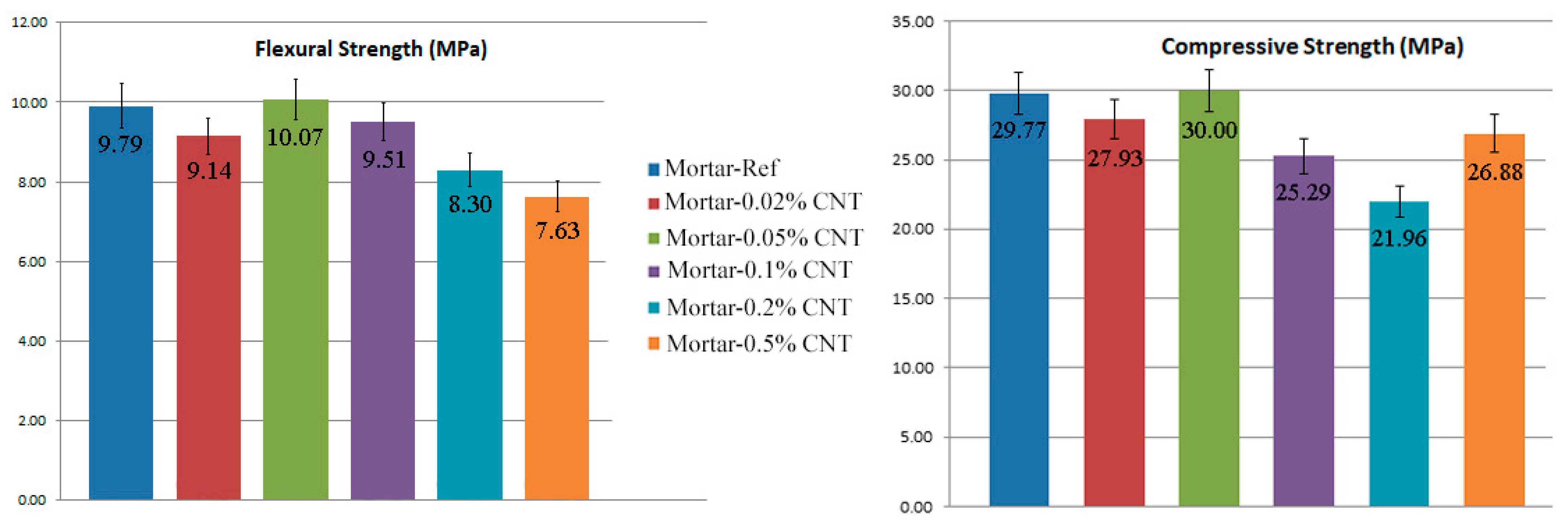
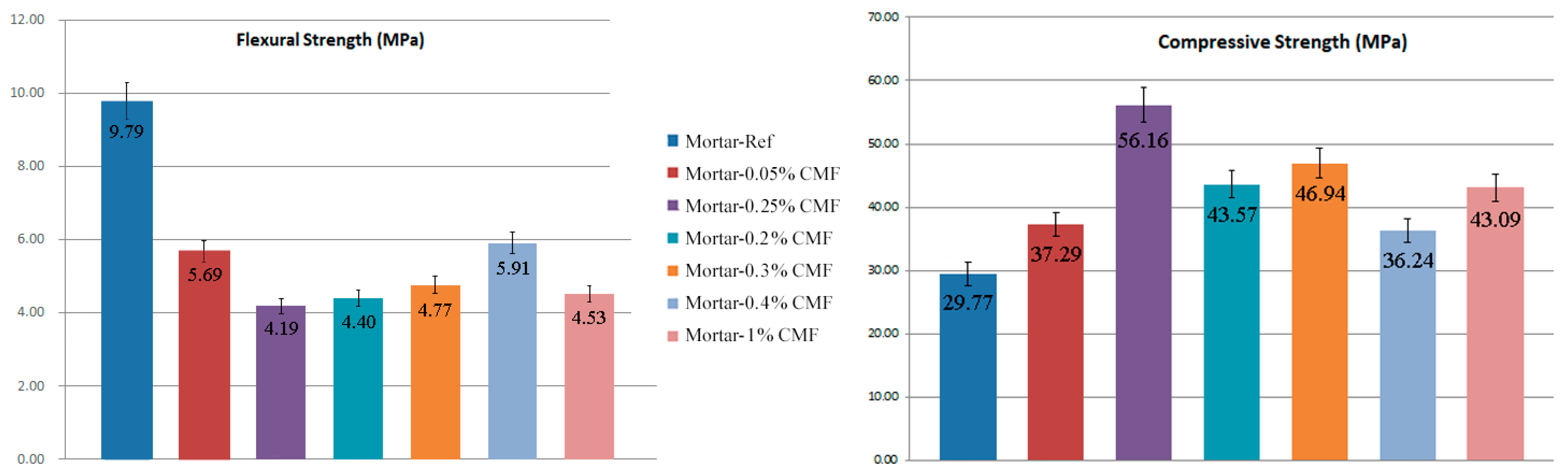
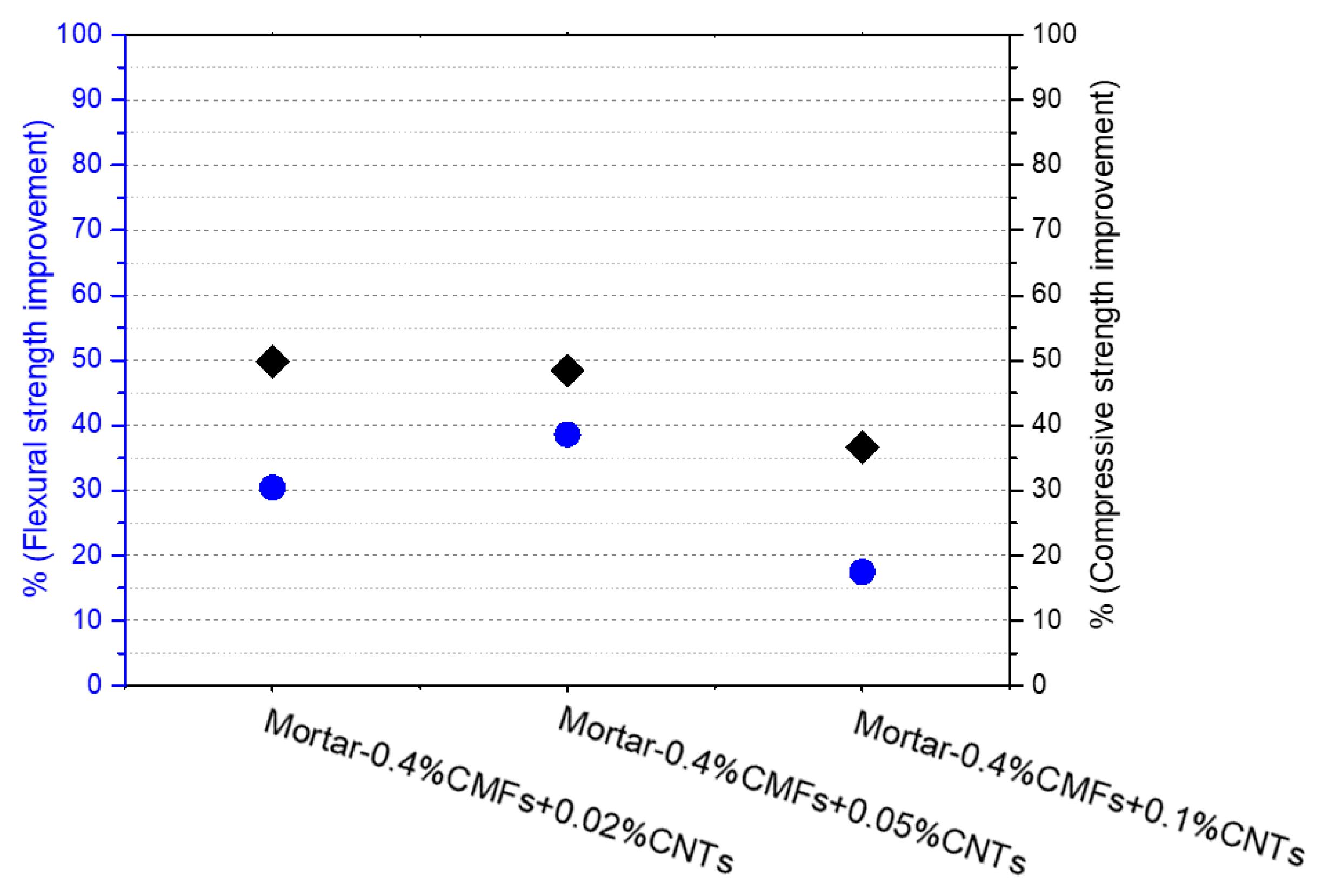
3.2. Mechanical Properties
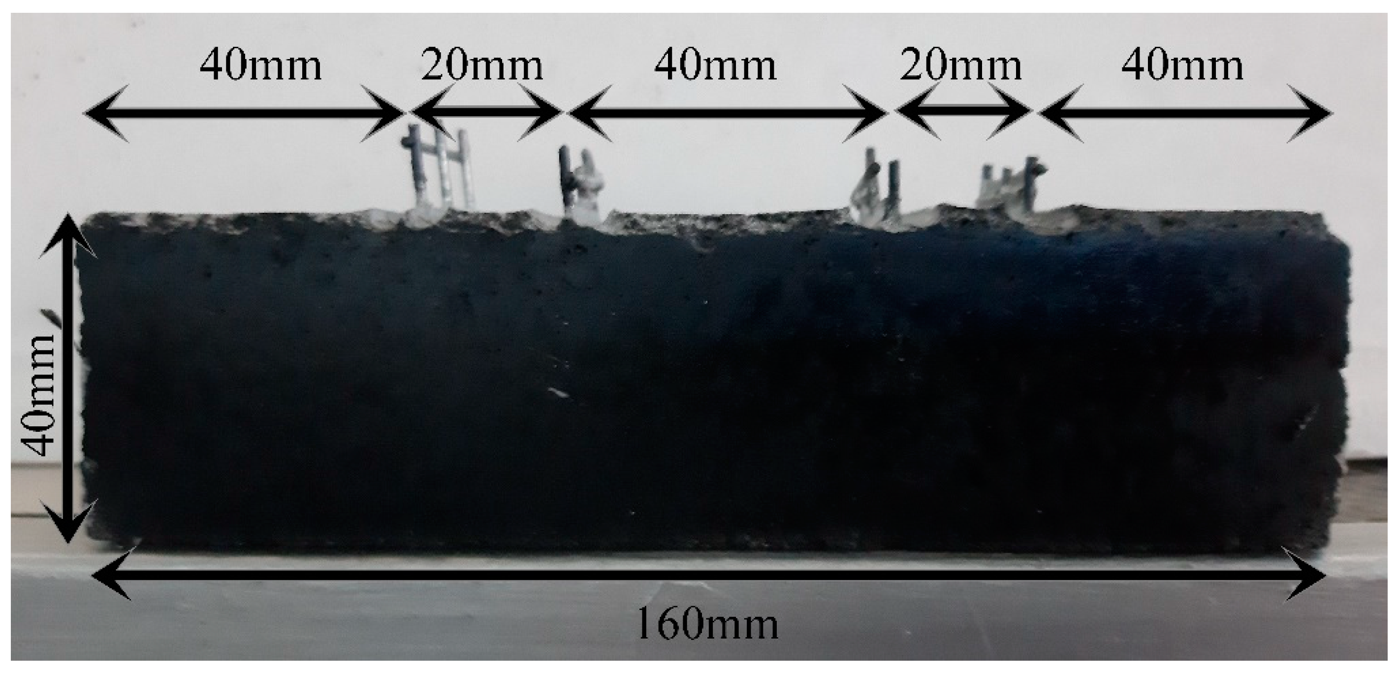
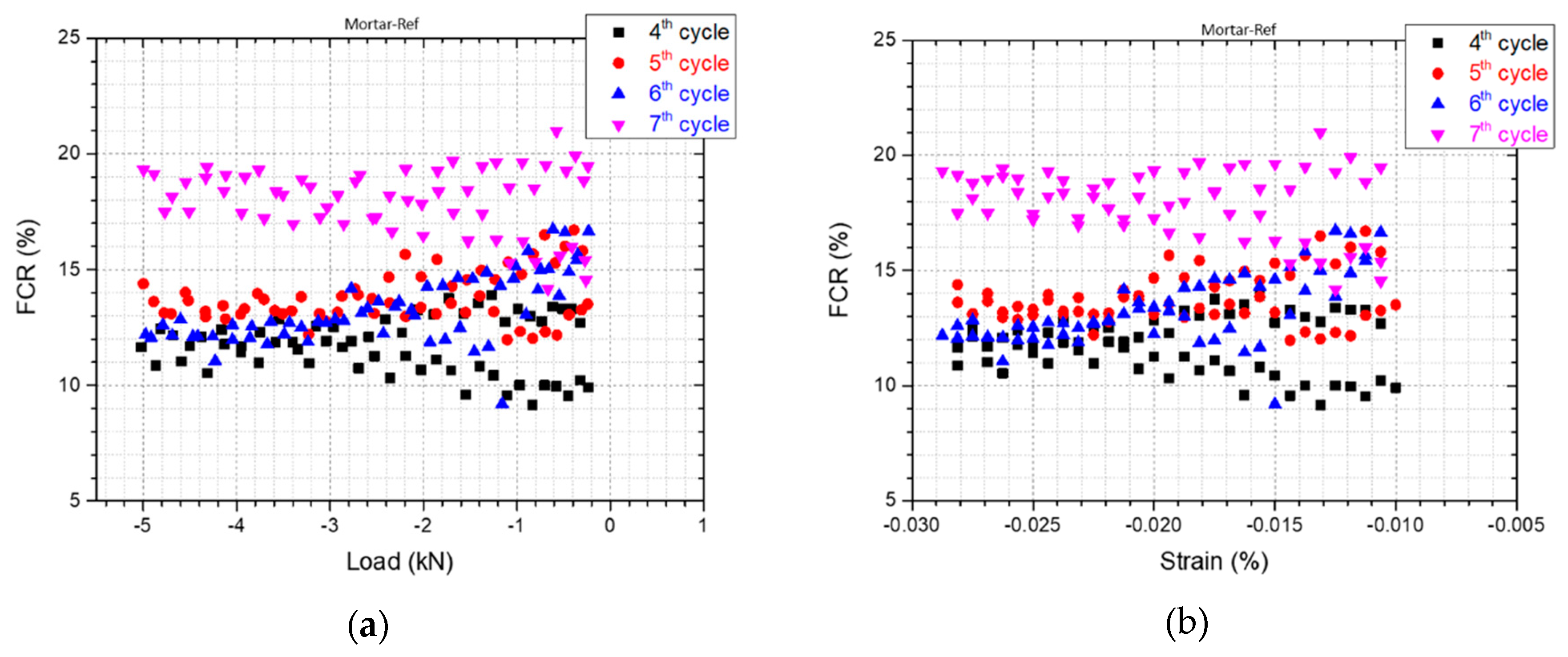
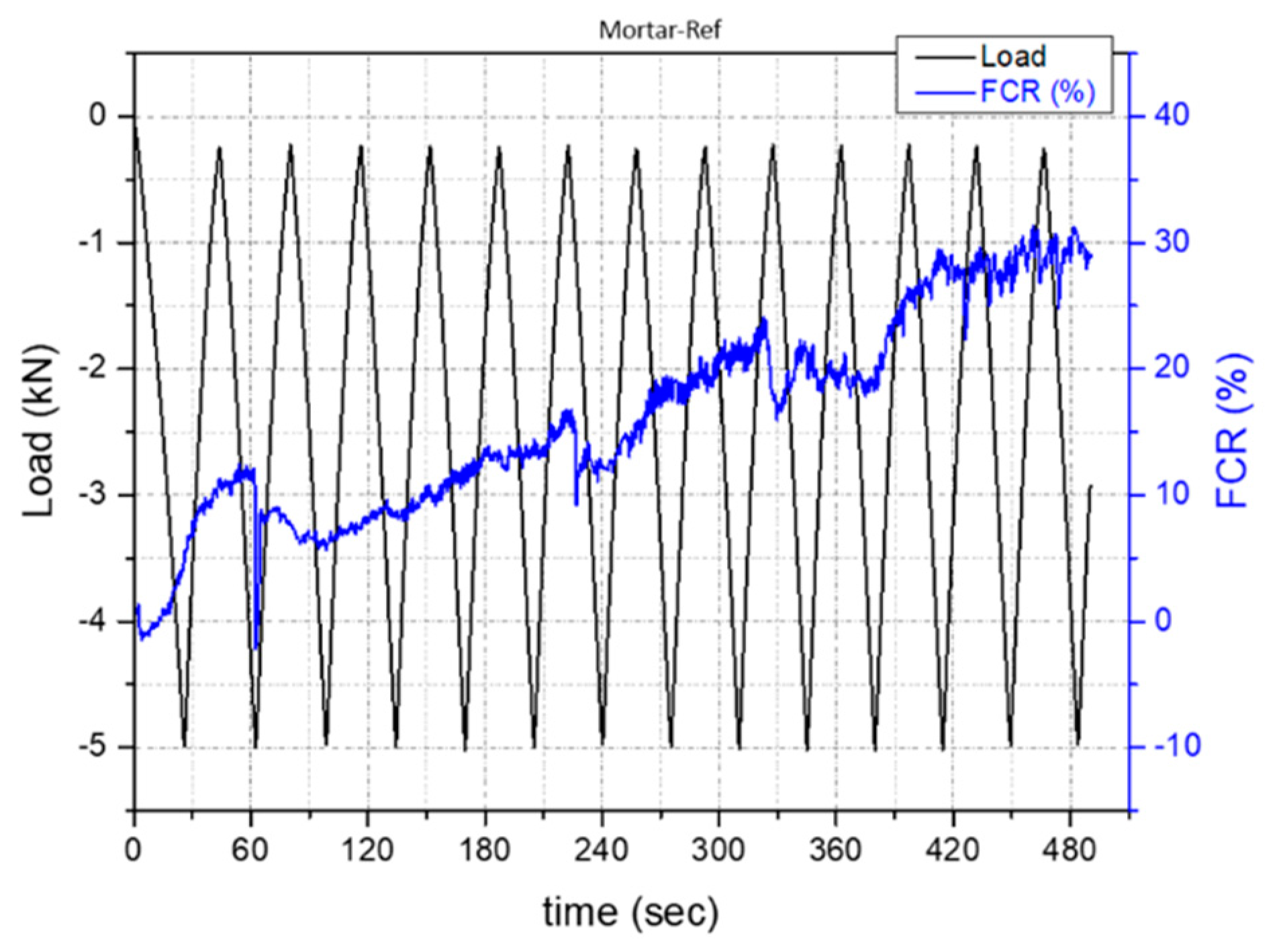
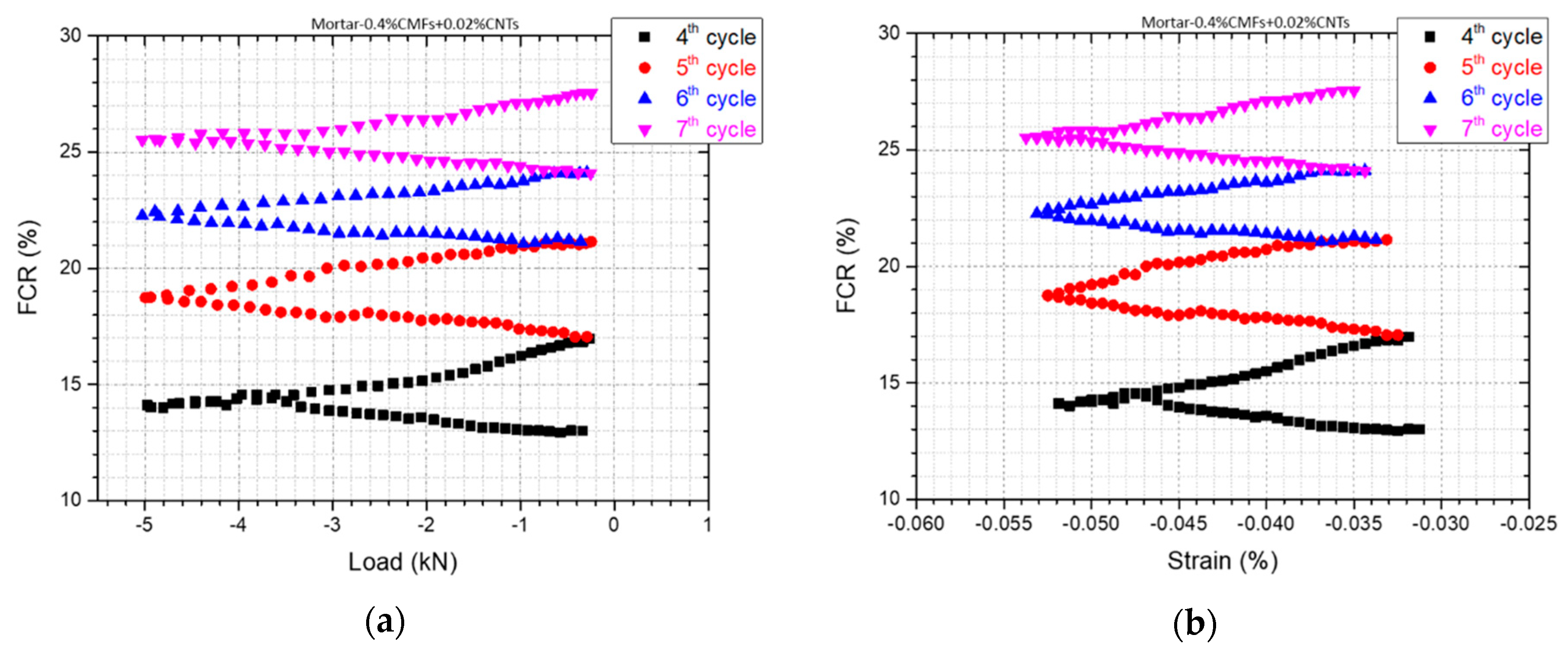
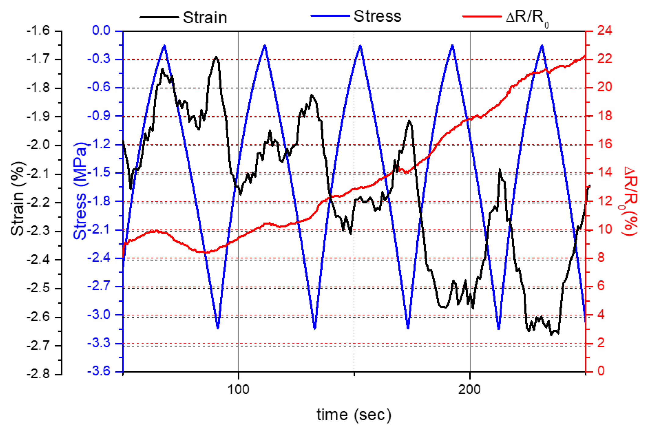
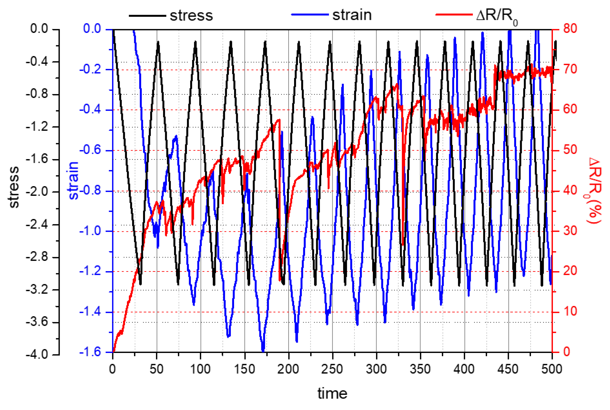
3.3. Self-Sensing Capacity
4. Conclusions
Author Contributions
Funding
Data Availability Statement
Conflicts of Interest
References
- Yang, G.; Zhao, J.; Wang, Y. Durability properties of sustainable alkali-activated cementitious materials as marine engineering material: A review. Mater. Today Sustain. 2021, 17, 100099. [Google Scholar] [CrossRef]
- Kanellopoulou, I.A.; Kartsonakis, I.A.; Charitidis, C.A. The Effect of Superabsorbent Polymers on the Microstructure and Self-Healing Properties of Cementitious-Based Composite Materials. Appl. Sci. 2021, 11, 700. [Google Scholar] [CrossRef]
- Ramezani, M.; Dehghani, A.; Sherif, M.M. Carbon nanotube reinforced cementitious composites: A comprehensive review. Constr. Build. Mater. 2022, 315, 125100. [Google Scholar] [CrossRef]
- Han, B.; Ding, S.; Yu, X. Intrinsic self-sensing concrete and structures: A review. Measurement 2015, 59, 110–128. [Google Scholar] [CrossRef]
- Ali, Z.; Yaqoob, S.; Yu, J.; D’Amore, A. Critical review on the characterization, preparation, and enhanced mechanical, thermal, and electrical properties of carbon nanotubes and their hybrid filler polymer composites for various applications. Compos. Part C Open Access 2024, 13, 100434. [Google Scholar] [CrossRef]
- Mittal, G.; Rhee, K.Y. Chemical vapor deposition-based grafting of CNTs onto basalt fabric and their reinforcement in epoxy-based composites. Compos. Sci. Technol. 2018, 165, 84–94. [Google Scholar] [CrossRef]
- Hamzaoui, R.; Bennabi, A.; Guessasma, S.; Khelifa, R.; Leklou, N. Optimal Carbon Nanotubes Concentration Incorporated in Mortar and Concrete. Adv. Mater. Res. 2012, 587, 107–110. [Google Scholar] [CrossRef]
- Silvestro, L.; Jean Paul Gleize, P. Effect of carbon nanotubes on compressive, flexural and tensile strengths of Portland cement-based materials: A systematic literature review. Constr. Build. Mater. 2020, 264, 120237. [Google Scholar] [CrossRef]
- Abu Al-Rub, R.K.; Tyson, B.M.; Yazdanbakhsh, A.; Grasley, Z. Mechanical Properties of Nanocomposite Cement Incorporating Surface-Treated and Untreated Carbon Nanotubes and Carbon Nanofibers. J. Nanomech. Micromech. 2012, 2, 1–6. [Google Scholar] [CrossRef]
- Evangelista, A.C.J.; de Morais, J.F.; Tam, V.; Soomro, M.; Torres Di Gregorio, L.; Haddad, A.N. Evaluation of Carbon Nanotube Incorporation in Cementitious Composite Materials. Materials 2019, 12, 1504. [Google Scholar] [CrossRef]
- Li, X.; Rafieepour, S.; Miska, S.Z.; Takach, N.E.; Ozbayoglu, E.; Yu, M.; Mata, C. Carbon nanotubes reinforced lightweight cement testing under tri-axial loading conditions. J. Pet. Sci. Eng. 2019, 174, 663–675. [Google Scholar] [CrossRef]
- Chen, S.J.; Collins, F.G.; Macleod, A.J.N.; Pan, Z.; Duan, W.H.; Wang, C.M. Carbon nanotube–cement composites: A retrospect. IES J. Part A Civ. Struct. Eng. 2011, 4, 254–265. [Google Scholar] [CrossRef]
- de Souza, T.C.; Pinto, G.; Cruz, V.S.; Moura, M.; Ladeira, L.O.; Calixto, J.M. Evaluation of the rheological behavior, hydration process, and mechanical strength of Portland cement pastes produced with carbon nanotubes synthesized directly on clinker. Constr. Build. Mater. 2020, 248, 118686. [Google Scholar] [CrossRef]
- Jung, M.; Lee, Y.-s.; Hong, S.-G.; Moon, J. Carbon nanotubes (CNTs) in ultra-high performance concrete (UHPC): Dispersion, mechanical properties, and electromagnetic interference (EMI) shielding effectiveness (SE). Cem. Concr. Res. 2020, 131, 106017. [Google Scholar] [CrossRef]
- Gao, J.; Sha, A.; Wang, Z.; Hu, L.; Yun, D.; Liu, Z.; Huang, Y. Characterization of carbon fiber distribution in cement-based composites by Computed Tomography. Constr. Build. Mater. 2018, 177, 134–147. [Google Scholar] [CrossRef]
- Chuang, W.; Geng-sheng, J.; Bing-liang, L.; Lei, P.; Ying, F.; Ni, G.; Ke-zhi, L. Dispersion of carbon fibers and conductivity of carbon fiber-reinforced cement-based composites. Ceram. Int. 2017, 43, 15122–15132. [Google Scholar] [CrossRef]
- Díaz, B.; Guitián, B.; Nóvoa, X.R.; Pérez, C. Analysis of the microstructure of carbon fibre reinforced cement pastes by impedance spectroscopy. Constr. Build. Mater. 2020, 243, 118207. [Google Scholar] [CrossRef]
- Tong, Z.; Guo, H.; Gao, J.; Wang, Z. A novel method for multi-scale carbon fiber distribution characterization in cement-based composites. Constr. Build. Mater. 2019, 218, 40–52. [Google Scholar] [CrossRef]
- Kim, G.M.; Park, S.M.; Ryu, G.U.; Lee, H.K. Electrical characteristics of hierarchical conductive pathways in cementitious composites incorporating CNT and carbon fiber. Cem. Concr. Compos. 2017, 82, 165–175. [Google Scholar] [CrossRef]
- Yoon, H.N.; Jang, D.; Lee, H.K.; Nam, I.W. Influence of carbon fiber additions on the electromagnetic wave shielding characteristics of CNT-cement composites. Constr. Build. Mater. 2021, 269, 121238. [Google Scholar] [CrossRef]
- Ijaz, H.; Mahmood, A.; Abdel-Daim, M.M.; Sarfraz, R.M.; Zaman, M.; Zafar, N.; Alshehery, S.; Salem-Bekhit, M.M.; Ali, M.A.; Eltayeb, L.B.; et al. Review on carbon nanotubes (CNTs) and their chemical and physical characteristics, with particular emphasis on potential applications in biomedicine. Inorg. Chem. Commun. 2023, 155, 111020. [Google Scholar] [CrossRef]
- Gamboa, A.; Fernandes, E.C. Resistive hydrogen sensors based on carbon nanotubes: A review. Sens. Actuators A Phys. 2024, 366, 115013. [Google Scholar] [CrossRef]
- Tundwal, A.; Kumar, H.; Binoj, B.J.; Sharma, R.; Kumari, R.; Yadav, A.; Kumar, G.; Dhayal, A.; Yadav, A.; Singh, D.; et al. Conducting polymers and carbon nanotubes in the field of environmental remediation: Sustainable developments. Coord. Chem. Rev. 2024, 500, 215533. [Google Scholar] [CrossRef]
- Dipta, I.K.R.A.; Lee, C.W. Recent advances and perspectives in carbon nanotube production from the electrochemical conversion of carbon dioxide. J. CO2 Util. 2024, 82, 102745. [Google Scholar] [CrossRef]
- Fang, Y.; Wang, J.; Ma, H.; Wang, L.; Qian, X.; Qiao, P. Performance enhancement of silica fume blended mortars using bio-functionalized nano-silica. Constr. Build. Mater. 2021, 312, 125467. [Google Scholar] [CrossRef]
- Chen, H.; Chen, Q.; Xu, Y.; Lawi, A.S. Effects of silica fume and Fly ash on properties of mortar reinforced with recycled-polypropylene. Constr. Build. Mater. 2022, 316, 125887. [Google Scholar] [CrossRef]
- Song, C.; Hong, G.; Choi, S. Effect of dispersibility of carbon nanotubes by silica fume on material properties of cement mortars: Hydration, pore structure, mechanical properties, self-desiccation, and autogenous shrinkage. Constr. Build. Mater. 2020, 265, 120318. [Google Scholar] [CrossRef]
- Kim, G.M.; Nam, I.W.; Yang, B.; Yoon, H.N.; Lee, H.K.; Park, S. Carbon nanotube (CNT) incorporated cementitious composites for functional construction materials: The state of the art. Compos. Struct. 2019, 227, 111244. [Google Scholar] [CrossRef]
- Kim, H.K.; Nam, I.W.; Lee, H.K. Enhanced effect of carbon nanotube on mechanical and electrical properties of cement composites by incorporation of silica fume. Compos. Struct. 2014, 107, 60–69. [Google Scholar] [CrossRef]
- Stynoski, P.; Mondal, P.; Marsh, C. Effects of silica additives on fracture properties of carbon nanotube and carbon fiber reinforced Portland cement mortar. Cem. Concr. Compos. 2015, 55, 232–240. [Google Scholar] [CrossRef]
- Lee, S.J.; You, I.; Zi, G.; Yoo, D.Y. Experimental Investigation of the Piezoresistive Properties of Cement Composites with Hybrid Carbon Fibers and Nanotubes. Sensors 2017, 17, 2516. [Google Scholar] [CrossRef] [PubMed]
- Garg, M.; Das, C.S.; Gupta, R. Use of silica particles to improve dispersion of -COOH CNTs/carbon fibers to produce HyFRCC. Constr. Build. Mater. 2020, 250, 118777. [Google Scholar] [CrossRef]
- Kim, G.M.; Yoon, H.N.; Lee, H.K. Autogenous shrinkage and electrical characteristics of cement pastes and mortars with carbon nanotube and carbon fiber. Constr. Build. Mater. 2018, 177, 428–435. [Google Scholar] [CrossRef]
- Zhan, M.; Pan, G.; Zhou, F.; Mi, R.; Shah, S.P. In situ-grown carbon nanotubes enhanced cement-based materials with multifunctionality. Cem. Concr. Compos. 2020, 108, 103518. [Google Scholar] [CrossRef]
- Zhou, Z.; Xie, N.; Cheng, X.; Feng, L.; Hou, P.; Huang, S.; Zhou, Z. Electrical properties of low dosage carbon nanofiber/cement composite: Percolation behavior and polarization effect. Cem. Concr. Compos. 2020, 109, 103539. [Google Scholar] [CrossRef]
- Ding, S.; Ruan, Y.; Yu, X.; Han, B.; Ni, Y.-Q. Self-monitoring of smart concrete column incorporating CNT/NCB composite fillers modified cementitious sensors. Constr. Build. Mater. 2019, 201, 127–137. [Google Scholar] [CrossRef]
- Collins, F.; Lambert, J.; Duan, W.H. The influences of admixtures on the dispersion, workability, and strength of carbon nanotube–OPC paste mixtures. Cem. Concr. Compos. 2012, 34, 201–207. [Google Scholar] [CrossRef]
- Punetha, V.D.; Rana, S.; Yoo, H.J.; Chaurasia, A.; McLeskey, J.T.; Ramasamy, M.S.; Sahoo, N.G.; Cho, J.W. Functionalization of carbon nanomaterials for advanced polymer nanocomposites: A comparison study between CNT and graphene. Prog. Polym. Sci. 2017, 67, 1–47. [Google Scholar] [CrossRef]
- Dubey, R.; Dutta, D.; Sarkar, A.; Chattopadhyay, P. Functionalized carbon nanotubes: Synthesis, properties and applications in water purification, drug delivery, and material and biomedical sciences. Nanoscale Adv. 2021, 3, 5722–5744. [Google Scholar] [CrossRef]
- Lavagna, L.; Nisticò, R.; Musso, S.; Pavese, M. Functionalization as a way to enhance dispersion of carbon nanotubes in matrices: A review. Mater. Today Chem. 2021, 20, 100477. [Google Scholar] [CrossRef]
- Meskher, H.; Ghernaout, D.; Thakur, A.K.; Jazi, F.S.; Alsalhy, Q.F.; Christopher, S.S.; Sathyamurhty, R.; Saidur, R. Prospects of functionalized carbon nanotubes for supercapacitors applications. Mater. Today Commun. 2024, 38, 108517. [Google Scholar] [CrossRef]
- EN 196-1:2016; Methods of Testing Cement—Part 1: Determination of Strength. European Committee for Standardization: Brussels, Belgium, 2016.
- Goulis, P.; Kartsonakis, I.A.; Mpalias, K.; Charitidis, C. Combined effects of multi-walled carbon nanotubes and lignin on polymer fiber-reinforced epoxy composites. Mater. Chem. Phys. 2018, 218, 18–27. [Google Scholar] [CrossRef]
- Trompeta, A.-F.A.; Koumoulos, E.P.; Kartsonakis, I.A.; Charitidis, C.A. Advanced characterization of by-product carbon film obtained by thermal chemical vapor deposition during CNT manufacturing. Manuf. Rev. 2017, 4, 7. [Google Scholar] [CrossRef]
- Environmental Product Declarartion for Portland Cement C, CEM I 42.5R & CEM I 52.5N, Programme: The International EPD® System; EPD registration number: S-P-03612; Valid until: 2026-06-02; EPD International AB: Stockholm, Sweden, 2021.
- Luo, T.; Hua, C.; Sun, Q.; Tang, L.; Yi, Y.; Pan, X. Early-Age Hydration Reaction and Strength Formation Mechanism of Solid Waste Silica Fume Modified Concrete. Molecules 2021, 26, 5663. [Google Scholar] [CrossRef]
- Kanellopoulou, I.; Karaxi, E.K.; Karatza, A.; Kartsonakis, I.A.; Charitidis, C.A. Effect of submicron admixtures on mechanical and self-healing properties of cement-based composites. Fatigue Fract. Eng. Mater. Struct. 2019, 42, 1494–1509. [Google Scholar] [CrossRef]
- Chung, D.L.D. Functional Materials: Electrical, Dielectric, Electromagnetic, Optical and Magnetic Applications (Engineering Materials for Technological Needs); World Scientific: Singapore; Hackensack, NJ, USA, 2010. [Google Scholar]
- Chung, D.D.L. A critical review of piezoresistivity and its application in electrical-resistance-based strain sensing. J. Mater. Sci. 2020, 55, 15367–15396. [Google Scholar] [CrossRef]
- Cwirzen, A.; Habermehl-Cwirzen, K. The Effect of Carbon Nano- and Microfibers on Strength and Residual Cumulative Strain of Mortars Subjected to Freeze-Thaw Cycles. J. Adv. Concr. Technol. 2013, 11, 80–88. [Google Scholar] [CrossRef]
- Wang, C.; Li, K.-Z.; Li, H.-J.; Jiao, G.-S.; Lu, J.; Hou, D.-S. Effect of carbon fiber dispersion on the mechanical properties of carbon fiber-reinforced cement-based composites. Mater. Sci. Eng. A 2008, 487, 52–57. [Google Scholar] [CrossRef]
- Lu, Z.; Hanif, A.; Sun, G.; Liang, R.; Parthasarathy, P.; Li, Z. Highly dispersed graphene oxide electrodeposited carbon fiber reinforced cement-based materials with enhanced mechanical properties. Cem. Concr. Compos. 2018, 87, 220–228. [Google Scholar] [CrossRef]
- Badalyan, M.M.; Muradyan, N.G.; Shainova, R.S.; Arzumanyan, A.A.; Kalantaryan, M.A.; Sukiasyan, R.R.; Yeranosyan, M.; Laroze, D.; Vardanyan, Y.V.; Barseghyan, M.G. Effect of Silica Fume Concentration and Water–Cement Ratio on the Compressive Strength of Cement-Based Mortars. Buildings 2024, 14, 757. [Google Scholar] [CrossRef]
- Han, B.; Yu, X.; Ou, J. Measurement of Sensing Signal of Self-Sensing Concrete. In Self-Sensing Concrete in Smart Structures; Butterworth-Heinemann: Oxford, UK, 2014; pp. 67–93. [Google Scholar] [CrossRef]
- Chung, D. Damage in cement-based materials, studied by electrical resistance measurement. Mater. Sci. Eng. R Rep. 2003, 42, 1–40. [Google Scholar] [CrossRef]
- Dang, N.; Tao, J.; Zeng, Q.; Zhao, W. May the Piezoresistivity of GNP-Modified Cement Mortar Be Related to Its Fractal Structure? Fractal Fract. 2021, 5, 148. [Google Scholar] [CrossRef]


| Composition | SiO2 | Al2O3 | Fe2O3 | CaO | MgO | SO3 | Na2O | K2O |
| % (mass) cement | 19.47 | 4.75 | 3.43 | 63.16 | 1.43 | 2.68 | 0.28 | 0.62 |
| Samples | Cement (g) | Silica Fume (g) | Sand (g) | Ratio w/c | H2O (mL) | Concentration CNTs (% bwoc) | Sika®Stabilizer-100 (g) |
|---|---|---|---|---|---|---|---|
| Mortar-Ref | 405 | 45 | 1350 | 0.5 | 225 | - | - |
| Mortar-0.02%CNT | 405 | 45 | 1350 | 0.5 | 225 | 0.02 | 0.25 |
| Mortar-0.05%CNT | 405 | 45 | 1350 | 0.5 | 225 | 0.05 | 0.625 |
| Mortar-0.1%CNT | 405 | 45 | 1350 | 0.7 | 315 | 0.1 | 1.25 |
| Mortar-0.2%CNT | 405 | 45 | 1350 | 0.7 | 315 | 0.2 | 2.5 |
| Mortar-0.5%CNT | 405 | 45 | 1350 | 0.7 | 315 | 0.5 | 6.25 |
| Samples | Cement (g) | Silica Fume (g) | Sand (g) | Ratio w/c | H2O (mL) | Concentration CMFs (%bwoc) | Sika®Stabilizer-100 (g) |
|---|---|---|---|---|---|---|---|
| Mortar-Ref | 405 | 45 | 1350 | 0.5 | 225 | - | - |
| Mortar-0.05%CMF | 405 | 45 | 1350 | 0.5 | 225 | 0.05 | 0.405 |
| Mortar-0.2%CMF | 405 | 45 | 1350 | 0.5 | 225 | 0.2 | 0.405 |
| Mortar-0.25%CMF | 405 | 45 | 1350 | 0.7 | 315 | 0.25 | 0.405 |
| Mortar-0.3%CMF | 405 | 45 | 1350 | 0.7 | 315 | 0.3 | 0.405 |
| Mortar-0.4%CMF | 405 | 45 | 1350 | 0.7 | 315 | 0.4 | 0.405 |
| Mortar-1%CMF | 405 | 45 | 1350 | 0.7 | 315 | 1 | 0.405 |
| Samples | Ratio w/c | H2O (mL) | Concentration CNTs (%bwoc) | Concentration CMFs (%bwoc) | Sika®Stabilizer-100 (g) |
|---|---|---|---|---|---|
| Mortar-Ref | 0.5 | 225 | - | - | - |
| Mortar-0.4%CMFs+0.02%CNTs | 0.5 | 225 | 0.02 | 0.04 | 0.225 |
| Mortar-0.4%CMFs+0.05%CNTs | 0.5 | 225 | 0.05 | 0.04 | 0.562 |
| Mortar-0.4%CMFs+0.1%CNTs | 0.5 | 225 | 0.1 | 0.04 | 1.125 |
| Electrical Resistivity (Ohm m) | |
|---|---|
| Mortar-Ref | 531.1 |
| Mortar-0.4%CMFs+0.02%CNTs | 254.3 |
| Mortar-0.4%CMFs+0.05%CNTs | 462.9 |
| CMFs + CNTs (%) | GF (Maximum) |
|---|---|
| 0.4 + 0.02 | 182 |
| 0.4 + 0.05 | 65,696 |
Disclaimer/Publisher’s Note: The statements, opinions and data contained in all publications are solely those of the individual author(s) and contributor(s) and not of MDPI and/or the editor(s). MDPI and/or the editor(s) disclaim responsibility for any injury to people or property resulting from any ideas, methods, instructions or products referred to in the content. |
© 2024 by the authors. Licensee MDPI, Basel, Switzerland. This article is an open access article distributed under the terms and conditions of the Creative Commons Attribution (CC BY) license (https://creativecommons.org/licenses/by/4.0/).
Share and Cite
Kanellopoulou, I.; Kartsonakis, I.A.; Chrysanthopoulou, A.I.; Charitidis, C.A. The Effect of Carbon Nanotubes and Carbon Microfibers on the Piezoresistive and Mechanical Properties of Mortar. Fibers 2024, 12, 62. https://doi.org/10.3390/fib12080062
Kanellopoulou I, Kartsonakis IA, Chrysanthopoulou AI, Charitidis CA. The Effect of Carbon Nanotubes and Carbon Microfibers on the Piezoresistive and Mechanical Properties of Mortar. Fibers. 2024; 12(8):62. https://doi.org/10.3390/fib12080062
Chicago/Turabian StyleKanellopoulou, Irene, Ioannis A. Kartsonakis, Athanasia I. Chrysanthopoulou, and Costas A. Charitidis. 2024. "The Effect of Carbon Nanotubes and Carbon Microfibers on the Piezoresistive and Mechanical Properties of Mortar" Fibers 12, no. 8: 62. https://doi.org/10.3390/fib12080062