Abstract
Steel fibre-reinforced concrete (SFRC) consists of short, hooked steel fibres that are randomly distributed and oriented within the cementitious matrix. This paper presents a new analytical load-bounding approach that captures the tensile response of misaligned fibres embedded in the matrix. The contribution of fibres in bridging cracks to provide the required stress transfer relies on the orientation of the fibres in the concrete. Bridging fibres aligned with a crack are less effective than those inclined to it. Therefore, understanding the pull-out behaviour of misaligned fibres is a key factor in quantifying and optimising the design of SFRC in structural applications. In the laboratory, a single-oriented fibre embedded in a solid cylinder of concrete was subjected to a pull-out test, where the axis of the tensile force is aligned with the axis of the cylinder. Based on the observed behaviour, this paper presents a new analytical bounding approach to capture the pull-out response of misaligned hooked-end steel fibres embedded in a concrete matrix. The analysis was based on a transversely isotropic failure criterion assumed for the plasticity that occurs in the cold-drawn fibre. Lower and upper bounds to the loading failure were derived from fibre pull-out and fibre fracture, respectively. The division between bounds depended upon the fibre orientation, fibre diameter and the combined strengths of the steel and concrete. Bounding predictions were drawn from ratios between a fibre’s shear strength and its transverse and axial uniaxial strengths, as found from a novel testing proposal. The two bounds were compared with new data and other experimental results published in the literature. The results showed that the region between the bounds captured the failure loads of embedded fibres with effective load-bearing orientations. A critical orientation was observed at maximum strength. The present interpretation of the plasticity occurring within off-axis, hooked-end steel fibres suggests that it is possible to optimise the strength of concrete using this method of reinforcement.
1. Introduction
It is inevitable that concrete structures are subjected to tensile stress during their service lives, whether this arises from shrinkage, flexural bending, or shear [1]. Consequently, there is a need to provide the structure with shear strength, flexural strength, ductility, and crack resistance. Because concrete does not inherently have good properties in each regard, it needs to be reinforced with an appropriate material in order to provide the performance required for an otherwise weak cementitious structure [2]. Steel has always been used and is still the most promising reinforcement, as it imparts both strength and stiffness to the composite, given that alloy steels combine high tensile strength with a high Young’s modulus. High tensile strength steel reinforcement is available as rebar, mesh, and fibres [3]. The latter, i.e., short-strand steel fibres, are available in different sizes, shapes, and alloy compositions. Of these, hooked-end steel fibres have recently received attention among engineers and researchers [4] aware of their continued resistance to tensile failure, even when the cementitious matrix bonding itself has suffered brittle failure from multiple tensile cracks.
The main contribution of fibre reinforcement is to absorb tension without brittle fracture. Tensile stress induced in the cementitious matrix is transferred to the steel fibre via the durable bond characteristics between both basic materials [5]. A fibre, mechanically pre-deformed with hooked ends, bonds to the matrix sufficiently well to resist the pull-out loading. A spread of randomly oriented and distributed fibres can resist micro-cracking at low loads more effectively [6]. For an individual fibre bridging a micro-crack, debonding starts along its short, 50-mm straight length under low loads. With increased loading, full debonding occurs [7]. There follows further micro-cracking leading, eventually leading to the formation of a macro-crack. The bond mechanisms between the fibre and matrix have been investigated to improve the mechanical performance of steel fibre-reinforced concrete (SFRC) [8]. Here, the interaction between interfacial bonds across many fibres in a cementitious matrix becomes active in providing increased resistance by prolonging the micro-cracking stage [9]. It follows that an SFRC with a large number of fibres contributes more to improving tensile resistance than another with a lower volume fraction within a similar grade of matrix material.
Numerous analytical and experimental studies have been carried out to investigate the fibre–matrix interfacial properties [10,11,12,13,14,15]. The majority of these investigations have been devoted to studying the bond characteristics when fibres are aligned with the loading direction [16,17]. Relatively few studies have been carried out on the bond behaviour of misaligned fibre reinforcement, which constitutes a more representative practical structure. It appears that the mechanisms governing pull-out behaviour of misaligned fibres differ from those experimentally verified for aligned fibres [18]. In addition to the mechanisms governing pull-out of aligned fibre, i.e., initial debonding followed by frictional pull-out, misaligned fibres introduce fibre bending, matrix spalling, and local friction effects, which promote fibre shank fracture before pull-out.
Only a few recent studies [19,20,21,22] have investigated the mechanisms governing the failure of inclined steel fibres in a cementitious matrix. It would appear from these studies that the existing theory is complicated by the many empirical parameters used to match specific experimental data. Thus, the predictions of real pull-out conditions are questionable across a wide variation in testing procedures that have been adopted in the absence of a standard test. Moreover, a shank failure invalidates an expectation of pull-out. In order to address this general practical concern, theoretical approaches have abounded on the specifics.
Soetens et al. [19] developed a semi-analytical model to simulate the pull-out behaviour of inclined fibres. They accounted for variations in mechanical and geometrical characteristics of the fibre, as well as the influence of fibre orientation.
Lee et al. [20] developed an analytical model to predict the pull-out response of inclined hooked-end fibres embedded in an ultra-high strength cementitious matrix. An apparent shear strength and slip coefficient were introduced to express the variation in peak pull-out load and peak slip.
Laranjeira et al. [21] proposed an analytical model to predict pull-out behaviour of inclined straight and hooked-end fibres. A multilinear diagram based on a set of key points was used to describe the pull-out slip response. Their model took into account debonding, friction effects, and matrix spalling due to variations in pull-out inclination.
Zhan et al. [22] developed an analytical model, similar to that in [21], in which the effect of the hooked-end was captured by a series of key stages in the force versus displacement response during pull-out. The force, calculated for each stage, augmented the theoretical force required for the pull-out of a straight fibre embedded with a similar inclination.
Building upon the investigations reviewed above, it is recognised that relatively few analyses have been made on the effects of fibre inclination angle on pull-out force should that mode of failure occur. Hence, the main intention of this paper is to offer an alternative global explanation of the failure behaviour that has been observed for inclined, hooked-end steel fibres. Here, both pull-out and shank failure of a fibre are admitted within the lower and upper bounds imposed. Critical forces found from the respective bound are validated against new laboratory test results and other relevant published data.
2. Analytical Pull-Out Model for Inclined Hooked-End Fibre
Figure 1a shows a single hooked-end, inclined steel fibre embedded in a concrete matrix. When the fibre orientation lies with an inclination to an externally applied tensile force , the stress state within the fibre is not unidirectional, consisting of axial, transverse, and shear components () aligned with the fibre co-ordinates (see Figure 1b). Laboratory testing of an inclined fibre provides the pull-out force applied horizontally to half the length of a single hooked-end embedded fibre for a useful inclination range: , as shown in Figure 2a. It is expected that the pull-out force first breaks the interface bond under a complex stress state in a similar manner to that explained above for a straight fibre. Then, with the fibre freed from the matrix, the stress components of the fibre shank (enlarged in Figure 1b) are provided by a simpler off-axis stress transformation under uniaxial loading [23].
where σ = F/A is the applied stress, found from the fibre section area over which is uniformly distributed at its half-length entry position, as shown in Figure 2a.
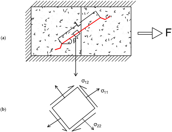
Figure 1.
Stress state for inclined hooked fibre embedded in cementitious matrix: (a) shows a single hooked-end inclined steel fibre embedded in a concrete matrix and (b) axial, transverse and shear components.
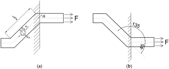
Figure 2.
Alternative left-side half-length arrangement used for (a) experiments and (b) bond failure prediction.
2.1. Fibre Failure Criteria
The transversely isotropic condition assumed here for the cold-drawn wire is similar to that which applies across a transverse section of a composite material in which many unidirectional fibres are embedded in a polymer resin matrix [24]. This composite has isotropic properties for all orientations in the plane of section 2–3 in Figure 3a, but is anisotropic, i.e., direction-dependent, in its two remaining orthogonal planes 1–2 and 1–3.
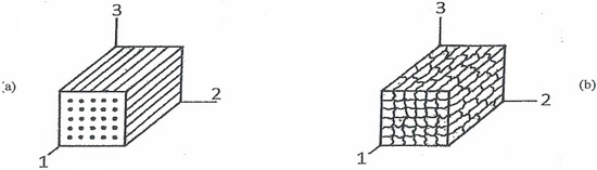
Figure 3.
Transversely isotropic plane (2B3) for (a) unidirectional fibres and (b) extruded grains.
Rolled sheet and cold-drawn metal wire have similar characteristics to those in Figure 3a, but to a lesser degree. Thus, in the plane 2B3 of the fibre cross-section shown in Figure 3b, the polycrystalline grains appear equiaxed and isotropic. However, in the extruded or cold-drawn direction (planes 1B2 and 1B3), elongated grains exhibited direction-dependent properties similar to a unidirectional reinforced composite. Hence, a transversely isotropic failure criterion was assumed for the fibre, which was deep-drawn to its final diameter (0.9 mm), having had its grains elongated by multiple reductions. Metallography revealed (see Figure 4a) elongated grains aligned with the fibres drawn in direction one, with an aspect ratio exceeding five. Figure 4b shows less directionality within a cross-section of an isotropic plane of the cross-section. The equiaxed grains that appeared had an average diameter of approximately 2 μm. Clearly, there were variations in grain size, but these did not appear in the macroscopic plasticity theory required for (i) a shank failure criterion at ultimate strength and (ii) straightening the fibre’s hooked ends during pull-out from the matrix.
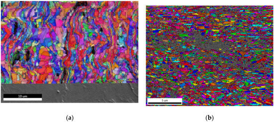
Figure 4.
Grain structures: (a) elongated and (b) transverse isotropy for deep-drawn fibre.
2.1.1. Transverse Isotropy
In Figure 2a, where the straight shank axis of a pre-bent fibre lies with an inclination θ to an applied tensile stress σ = F/A, a plane stress state (Equations (1)–(3)) exists within the fibre. Correspondingly, the fibre’s off-axis failure criterion for the plane stress state, shown in Figure 1b and Figure 2a, appears in a non-dimensional form [25]:
where σ1f, σ2f, and σ12f are, respectively, the ultimate strengths of the fibre in axial tension, transverse tension, and shear. Substituting Equations (1)–(3) into Equation (4) provides an off-axis failure criterion in terms of the applied tensile stress and fibre inclination:
in which σ = σθ = F/A is the applied tensile stress in the fibre with an inclination θ. Re-arranging Equation (5) provides the limiting applied stress (failure stress) σθ for an inclined fibre B, written in a normalised form to enable the off-axis strength to be compared more conveniently with experimental data:
σ11 (σ11 − σ22)/σ1f 2 + σ222/σ2f 2 + σ12 2/σ12f 2 = 1
(σ2cos2θ/σ1f2)(cos2θ − sin2θ) + (σ2sin4θ)/(σ2f 2) + (σ2sin22θ)/(4σ12 f 2) = 1
(σθ/σ1f)2 [cos2θ cos2θ + (σ1f/σ2f)2 sin4θ + (1/4) (σ1f/σ12f)2 sin22θ] = 1
As a check upon Equation (6), the oriented strengths in tension, compression, and shear are provided by orientations θ = 0°, 90°, and 45° respectively:
θ = 0°; (σ0°/σ1f)2 = 1, ∴ σ0° = σ1f
θ = 90°; (σ90°/σ2f)2 = 1, ∴ σ90° = σ2f, σ90°/σ1f = σ2f/σ1f
θ = 45°; (1/4) (σ45°/σ12f)2 = 1, ∴ σ45° = 2 σ12f, σ45°/σ1f = (2σ12f/σ1f)
An isotropic prediction (von Mises) from Equation (6) applies when: σ1f/σ2f = 1 and σ1f/σ12f = :
σθ/σ1f = (cos2θ cos2θ + sin4θ + (3/4) sin22θ) −1/2
Then, Equation (7) is equivalent to:
which predicts, as expected, a fibre strength that is not orientation-dependent. More realistically, anisotropic (orientation-dependent) strength ratios between the ultimate strengths in axial tension σ1f, transverse tension σ2f, and shear σ12f might be expected to lie in the range:
σθ/σ1f = (sin2θ + cos2θ) −1 = 1
4/3 < (σ1f/σ2f, σ1f/σ12f) < 2
or 2 < (σ2f/σ1f, σ12f/σ1f) < ¾
For example, Figure 5 shows one anisotropic off-axis plot according to Equation (6) for cold-drawn high-strength steel fibre, for which the two strength ratios in Equation (10) are assumed equal to two. This means that when θ = 90°, σθ = σ2f = σ1f/2 at the strength ratio assumed. Equation (6) applies only beyond a critical fibre orientation where the hooked end of the fibre is able to prevent slip by pull-out. Here, the fibre shank would fail to attain its tensile strength in bridging the gap between the free surfaces created by cracking in the concrete matrix. This is unlikely to occur for small orientations, given those experiments (3B5) on aligned fibres, which show that when pulled axially, a fibre slips out from its matrix accommodated by plastic unhinging of its hooked ends. Here, the maximum stress reached in the fibre under the maximum pull-out force is less (the lower bound) than its ultimate strength.
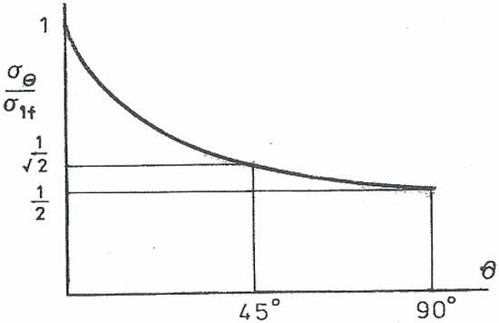
Figure 5.
Off-axis strength variation of anisotropic fibre for which σ2f/σ1f = σ12f/σ1f = 2.
The full strength of an inclined fibre shank is reached (upper bound) only in the absence of matrix spalling (brittle crumbling) at the fibre’s entry position on the cracked surface. Spalling enables the fibre to bend more easily into alignment with the increasing force, thereby widening the gap between the crack surfaces with a reduced embedded length [21]. It is expected, therefore, that an upper bound applies in the absence of spalling in a higher-quality cementitious matrix. It follows that inclined fibre pull-out is a complex combination of mechanisms and material behaviour, all of which depend upon the inclination in some manner. Despite these difficulties, it is possible to simplify critical applied force predictions using a global approach that subsumes these contributory factors. Here, the following bounds were placed on the applied force associated with the pull-out of inclined fibres, where this was likely to be interrupted by a fibre breakage.
2.1.2. Upper and Lower Bounds
An upper bound, representing the maximum pulling force, is provided when, as here, it is based on the influence of orientation on the fibre’s nominal strength σθ = F/A. Note: Each transversely isotropic strength σ1f, σ2f and σ12f in Equation (6) is a fixed material property referred to the 0°, 90° and 45° orientations. The lower bound inclined pulling force assumes a slip failure from unhinging at the fibre bend under its axial force component Fcosθ, as shown in Figure 2a. Thus, an inclined pull-out force is magnified by the factor 1/cosθ compared to the force required to pull out a fibre without an inclination (i.e., for θ = 0° in Figure 1a). That is:
where forces Fθ and F0° may be referred to the fibre’s cross-sectional area A in terms of nominal stress:
Fθ = (F0°/cosθ)
σθ = (σ0°/cosθ)
A lower bound non-dimensional prediction of σθ follows from Equation (11) by dividing by the fibre’s axial tensile strength:
σθ /σ1 f = (1/cosθ) (σ0°/σ1f) < 1
While a lower bound σθ/σ1f can be calculated from Equation (12) over a full inclination range of 0° < θ < 90°, it is cut off at the intersection with an upper bound from the failure criterion for an inclined fibre. It has been observed that the failure stress remains constant at all orientations for an isotropic fibre, as Equation (8) has shown. Otherwise, Equation (6) shows that the failure stress σθ is orientation-dependent, involving a transversely isotropic fibre’s anisotropic strength ratios σ1f/σ2f and σ1f/σ12f. For example, with each ratio at ½, Figure 5 shows that the upper bound failure stress decreases with increasing orientation from a maximum value of unity, corresponding to the ultimate tensile strength (UTS) of an aligned fibre (θ = 0°). This is far greater than the lower bound stress calculated from the force observed for the complete pull-out of an aligned fibre. The resolution of the inclined force (i.e., nominal stress) also shows normal and tangential shear stress in Equations (1)–(3), acting upon an inclined fibre (see Figure 1b), thereby reducing its resistance to pull-out from a high-strength matrix. Where a weaker matrix is damaged around the fibre at the entry to a crack surface, the re-entrant bending that occurs aids pull-out through a pincer action. It is concluded from these observations that a lower bound pull-out force for inclined fibre need not consider opposing influences that promote a slightly greater or lesser value than that found here from basic force resolution. Thus, for design requirements, it is expected that all experimental data would lie between the upper and lower bounds, thereby obviating the complexity involved in considering a more precise integration of all orientation-dependent mechanisms [21]. Taking only the peak loading applies to shallow orientations where a fibre does pull out fully under a slightly increased force compared to an aligned fibre. However, with increasing fibre orientation, the spalling damage it produces in the concrete around the fibre entry aids its release. It is expected that fibre rupture will occur consistently at and beyond a critical orientation.
2.1.3. Experimental Data
In Figure 6a–d, the peak value of the applied nominal stress σθ for an inclined fibre is normalised with the UTS (σ1f) of an aligned fibre. It follows from Equation (6) that the uniaxial strength σ1f can never be attained in the failure of an embedded inclined fibre. Therefore, a restriction must be placed on the range of strength ratios employed for an upper bound plot. With increasing θ, the reduced strength range for inclined fibre failure appears in the upper bound plot. Upper bounds, shown in Figure 6a–d, are based on fibres having transverse and shear strengths equal to 50% to 75% of the axial strength, i.e., strength ratios of ½ and ¾, as given in Equation (10).
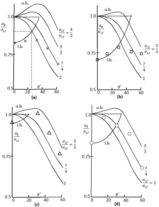
Figure 6.
Peak stress dependency on fibre inclination. Key: (u. b. upper bounds, l. b. lower bound).
It is observed that the upper and lower bounds predicted from Equations (6) and (10) capture published data [26,27,28] on fibre fracture for orientations 30° < θ < 60°, despite the wide variation in fibre diameter and tensile strength (Figure 6b–d: 0.5 mm, 1150 MPa [26]; 0.8 mm, 2117 MPa [27]; 1.0 mm, 860 MPa [25]). For these fibres and the test data in Figure 6a, it appears that for a 0.9 mm fibre with UTS = 860 MPa, all fibre strength ratio combinations lie within the range given in Equation (9) for their match. This shows that a close u. b. fit applies to equal strength ratios (σ1f/σ2f = σ1f/σ12f = 7/4), as assumed in Figure 5. Experimental methods for the determination of strength ratios follow. All results in Figure 6a–d apply to a high-strength concrete matrix in which, with spalling effects minimised, embedded fibre shank failures appeared with increasing orientation. Fibre shank failures provide upper bound solutions. Otherwise, it is observed that a lower bound, pull-out prediction from Equation (12) is adequate for fibre pull-out with lesser orientations in the range of 0° < θ < 30°. As θ increases, a critical σθ value divides the bounds. This value is found by equating Equations (6) and (12). For example, with σ1f/σ2f = σ1f/σ12f = 2,
giving, in Figure 6a, θc ~ 25° and σθ/σ1f ~ 0.9, where an aligned fibre intercept value σ0°/σ1f = 0.82 applies to σ1f/σ2f = 2, as shown. In a similar manner, other data (see Figure 6b–d), taken from the literature [26,27,28], lie between the two bounds when normalised with σ1f. Note: the nominal, critical applied stress ratio in Figure 6a–d interchanges directly with the ratio between the maximum pull-out/fracture force Fθ and the ultimate tensile force F0° for a 0° fibre with diameter d. That is:
(1/cos2θ)(σ0°/σ1f)2 (cos2θ cos2θ + 4sin4θ + sin22θ) = 1
(cos2θ + 4 sin4θ/cos2θ + 4sin2θ) = (σ1f/σ0°)2
Fθ/F0° = [(πd2/4) × σθ]/[(πd2/4) × σ1f] = σθ/σ1f
Note: F0° = σ1f × πd 2/4 is the ultimate tensile force for an aligned fibre. This is found from a standard tensile test in which σ1f corresponds to the fibre’s UTS. In Equation (14), Fθ = σθ × πd2/4 refers to either the maximum pull-out load or the fibre shank failure load, as observed from a withdrawal test upon an embedded, inclined fibre. Other tests that follow are required to determine the ultimate strength of the fibre in its transverse direction (σ1f) and under shear (σ12f), as the strength ratios appearing in Equation (6) need to be determined experimentally.
2.2. Fibre Strength Tests
High-tensile drawn wire is usually supplied with its strength and ductility properties aligned with the length direction. Equation (6) shows that in addition to the axial strength σ1f, the transverse strength σ2f and shear strength σ12f are necessary for an off-axis failure prediction. The wire is usually supplied with its uniaxial tensile strength only, denoted here as σ1f. It is most convenient to establish σ2f and σ12f from transverse compression and double shear tests using indenters between guides, as shown in Figure 7a,b, respectively. In the absence of hardening for a high strength 0.9 mm alloy steel wire (supplier Bekaert Dramix, Belgium), the minimum ultimate transverse strength σ2f is estimated from the load WE at full elastic compression:
where b is the die breadth and d is the wire diameter (see Figure 7a).
σ2f = WE/(bd)
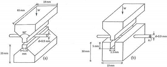
Figure 7.
Transverse compression (a) and double shear (b) tests for σ2f and σ12f.
Here, bd is the projected rectangular area under compression lying beneath the die within the wire’s central horizontal plane. The maximum transverse strength applies to the wire’s centre, where the principal lateral stresses σ2 and σ3 (co-ordinates 2 and 3 in Figure 3b) attain their maxima in compression and tension, respectively [26]:
σ2 = − (6WE)/(πdb) and σ3 = (2WE)/(πdb),
These combine to give a transverse, effective yield strength:
The coefficient 2.3 in Equation (16) is lowered to 2.23 when an axial stress σ1 = v(σ2 + σ3) is taken for the contact zone, with v = 1/4, to account for negligible axial strain due to being constrained by each unstrained length beyond the contact length b.
Ideally, an axial torsion test would be required to determine the shear strength σ12f, as required in Equation (6). The torque required to produce a fully plastic circular section has been well documented [4]. It is given as 4/3 times the yield torque:
where k, the shear yield stress, may be equated to σ12f in the absence of hardening. If a fine wire torsion machine is not available to determine Tult, then a transverse shear stress in the plane 2–3 of Figure 3b can be taken as the complement of σ12 in Figure 1b. Hence, under double shear (see Figure 7b), the shear strength of the fibre is approximated as:
in which there are two wire cross-section areas resisting the total transverse shear load W. More precisely, the maximum shear stress at the centre of a solid circular section under a single shear is given by 4W/3A [27]. It follows that, under double shear, the coefficient of 2 in Equation (17) becomes: 1/2 × 4/3 = 2/3. This gives:
Tult = 4/3 × πkr3/2
σ12f = (WS)/(2A)
σ12f = (2WS)/(3A)
Results and calculations of the strength ratios are shown in Table 1. Transverse and shear strength estimates were calculated as described above using Equations (16) and (18), with a die breadth b = 2.5 mm and high tensile wire of diameter (d = 0.9 mm), supplied with a given axial strength σ1f in three hook geometries.

Table 1.
Fibre strengths (MPa) from transverse compression (σ2f) and double shear (σ12f).
2.3. Matrix Composition and Materials
The composition, grading, and measured basic mechanical behaviour of the concrete matrix are summarized in Table 2. The mix included Portland limestone cement CEM II 32,5R, fine aggregates (0–4 mm), and coarse aggregates (6–10 mm), with 200 kg/m³ of water. The water-to-binder (W/B) ratio was 0.55. This mix was designed to achieve a compressive strength of 32 MPa after 28 days, indicating its suitability for normal-strength concrete applications. Additionally, the estimated modulus of elasticity after 28 days was 26,700 MPa, reflecting the concrete’s stiffness and resistance to deformation under load. These properties make the mix appropriate for various structural uses where moderate strength and stiffness are required. The mixing procedure, sample preparation, and testing method can be found elsewhere [4].
Table 2.
Materials and matrix mix proportions.
3. Pull-Out Tests of Inclined Fibres
Figure 8 shows the effect of inclination angle on the maximum pull-out load (Fθ) of inclined hooked-end fibres with the following inclinations: 0°, 15°, 30°, 45° and 60°. The mechanisms governing the pull-out behaviour of inclined hooked-end fibre were found to be similar to those in aligned straight fibres. These were initial debonding, followed by unbending, then frictional pull-out of the straightened fibre. First, the force applied overcame a chemical bonding and frictional resistance from the interface to the fibre. Slip occurred when an increased force released the mechanical anchorage provided by the hooked end. The unbending required for this release involved plastic deformation within hinges that formed successively at each bend of the fibre hook. When straightened, the complete pull-out of the fibre occurred under a much lower force that equated to the remaining sliding friction. The mechanical anchorage contribution provided by a hooked-end fibre significantly increased the pull-out load after debonding. In contrast, following the debonding of an embedded straight fibre, only frictional resistance remained to be overcome under a falling load. The pull-out load versus slip responses shown in Figure 8 reveal the load variations found from separate pull-out tests upon hooked-end fibres at five different orientations.
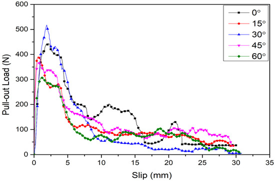
Figure 8.
Pull-out load vs. slip of inclined hooked-end fibre.
The pull-out plots are often presented as an average of a number of tests conducted under similar controlled test conditions, including temperature, straining rate, loading alignment, and material composition consistency. Although averaging removes vibrational scatter in the loading, an irregularity remains in each plot, which can hinder an accurate prediction. Despite this, most reports on pull-out testing continue to identify a sequence of failure events within the plot of pull-out load versus fibre slip [1,2,3,4,5,6,7,8,9,10,11,12,13,14,15,16,17,18,19,20]. The first event is the region along a rising curve within which fibre debonding has occurred. Thereafter, each flat load plateau is identified [20] with the bending required to straighten the fibre hook prior to its complete removal from the matrix at a slip displacement, which equals 30 mm as a straightened embedded length (see Figure 8). The anchorage offered by the hooked end raises the load to the maximum observed, which is required for straightening the fibre at its first bend. Thereafter, lower load plateaus have been associated successively with bending at the trailing ends of the hook, as necessary for the fibre to slip further in the straight region of the matrix tunnel. Some erosion of that straight region occurs with spalling in the matrix around the fibre at its exit surface. Therein, with some loss of fibre orientation, further load plateaus appear less distinct, and the number of these plateaus depends on the hook design. Spalling becomes more severe in fibres with a larger inclination to the pulling force. A bending of the fibre in a spalled surface cavity leads to premature failure [18,19,20,21] of the fibre before its complete removal. Such behaviour has motivated the present bounding approach to account for steeper fibre inclinations under loading, where fibre fracture interrupts complete withdrawal. Invoked by the bounding approach, the critical load for an incomplete pull-out, i.e., from fibre fracture, lends itself to a division between its upper and lower bound limits. It is also suggested here that a further intermediate bound be placed on the tensile strength of the concrete at the interface region where spalling occurs. The ratio of tensile strength of the concrete is a small fraction of that of the steel fibre. Consequently, spalling is expected to occur around the fibre’s entry position to a freed crack surface under a relatively low pull-out load. This behaviour arises in practice when a randomly orientated fibre distribution serves to bridge free crack surfaces that arise in a concrete matrix under service loading conditions, i.e., the primary role of reinforcement. In serving this role, a bridging fibre with an orientation is more likely to create a spalling cavity than an aligned fibre. Pulling on a misaligned fibre creates a bending moment at the entry to the matrix. Quite apart from its contribution to fibre failure, this bending imparts both tension and compression to the surrounding matrix, with the concrete on its tensile side being most likely to spall. There may appear opposing forces at work here. While spalling acts to lessen resistance to pull out, the shank inclination increases that resistance in a lower bound mode (see Figure 6a–d). Conversely, the upper bound mode shows that shank failure stress is reduced as the plane stress state (Figure 2a) within it is accentuated by the fibre’s orientation. The interplay between such influences upon the failure stress (i.e., the ‘pull-out force per unit area) depends on the orientation in a manner suggested by bounding failures: a lower bound failure from the complete pull-out of slightly misaligned fibre, and an upper bound shank failure for misaligned fibre beyond a critical orientation. In Figure 6a–d the unit ordinate cuts off a l. b. failure, i.e., when the applied stress attains the ultimate strength of the fibre. The experiment shows that this condition is never attained. Thus, with the straightening of the hook end, preceding its complete withdrawal, the applied stress is less than the ultimate strength. Fibre pull-out appears to be most consistent with an aligned stress condition. The implication drawn from Figure 6 is that a l. b. fibre pull-out applies only to a low range of ‘misaligned’ fibre. Figure 6 safely suggests that a range of θ < 10° applies to a l. b. pull-out plot before it is intercepted by an upper-bound fibre failure. The latter requires less loading to be applied to induce failure in the fibre with increasing orientation, as the stress components seen within the plane stress state, shown in Figure 1b, increase. Thus, a combined stress failure in an off-axis fibre occurs under an applied load less than the load required for a uniaxial tensile failure of an aligned fibre. The combined loading may also involve flexure of a fibre within a spalled cavity and further surface shear from any fibre slip from within the surrounding matrix. Again, each influence would contribute to combined stress yielding under a lower applied load compared to the load necessary for uniaxial yielding to occur. The experimental data lends support to the yield criterion. It can be observed in Figure 9 that the maximum pull-out load at 15° and 30° fibre shank inclinations are 3.2% and 5.3% higher than that for an aligned fire shank (0°). At 45° and 60° inclinations, the maximum pull-out load is 20.2% and 36.8% less than that of the aligned fibre. The maximum pull-out load of hooked-end fibres increased with an inclination angle of up to 30°, in accordance with the lower bound Equation (12). At greater inclinations of 45°and 60°, an upper bound failure occurs assisted by spalling. Here, with a fibre failure, a full deformation is reached in the shank at ultimate strength before the end can straighten to facilitate pull-out. Despite the change in failure mode, it is observed that the upper bound loading remains high within the orientation-dependent strength of cold-drawn steel fibre. Lower bound loads involve plastic hinging under flexure but at lower loading than that required to produce an off-axis tensile shank failure.
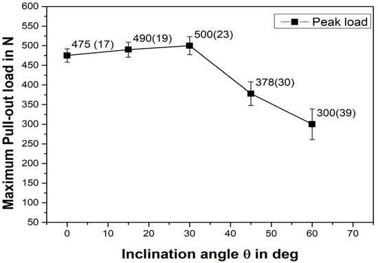
Figure 9.
Maximum pull-out load vs. fibre inclination.
The maximum pull-out load is observed for a fibre inclination of 30°. This is explained by a change in deformation mode, from plastic unhinging in the hook to shank plasticity, the latter reminiscent of triaxial necking in a tension test. Adding to the complexity of pull-out plasticity, the applied force must overcome the frictional resistance at the fibre bend when interfaced with coarse aggregate and also account for any relief in that force from the freed interface surface arising from the spalling that occurs. In combination, it appears that the respective changes in force cancel out such spurious influences, consistent with the force-bounding estimates given here. It appears from the peak loading plot that fibre orientations are resistant to tensile failure within a narrow range of 10°–30°. Here, a tensile failure of the fibre shank is preceded by a localised necking. This behaviour is similar to that when instability occurs under maximum load in a simple tensile test [26]. There, the inception of a neck corresponds to the ultimate tensile strength (UTS). The ultimate strength of the fibre equals its yield stress in a non-hardening material, as is the case here with a heavily drawn 1-mm fibre made of high-strength steel. An upper bound is derived by assuming a necking condition for the embedded fibre despite the low orientation, which only marginally augments the neck’s triaxial stress state. Fibre pull-out is more likely to occur for an aligned fibre (0°) because lower loading is required for sequential bond release and plastic unbending of the hook. Here, the lower bound assumes that complete pull-out of the hook will occur in the absence of tensile necking. These comments on two different failure modes within the embedded fibre are based upon the experimental observations reported herein. It is more likely that a fibre will pull out completely when the inclination between the fibre and the applied force is shallow. A low shank inclination enables the fibre hook to unbend and release completely more easily than a shank with a steeper inclination. The latter, when at 30 degrees, promotes failure in the fibre shank due to the off-axis stress state that prevails in a necking failure. Greater inclinations enhance the contribution from shear and transverse stress so that the axial stress, and hence the applied force, are lesser. Briefly, as the inclination increases, the non-uniaxial plane stress state becomes more severe, which lessens the applied force necessary to attain the fibre’s yield stress.
4. Bounding Model Refinements
In order to ascertain the reliability of the proposed approach to describe the failure of inclined hooked end fibres, various experimental results from data published in the literature [25,28,29] have been compared with the bounds found from Equations (6) and (12). The experimental data were chosen primarily to account for the embedded strength of hooked-end fibres with different shank orientations. Other variables included fibre diameter, the tensile strength of the fibre, and the compressive strength of the concrete. In the experiments, the embedded shank half-length varied together with its hook end geometry. The upper bound (u. b.) did not explicitly require these specific details, only that the hook provided sufficient anchorage for a shank failure to occur. The diameter appeared in the calculation for the nominal stress σθ under the applied force, and the diameter was also maintained during testing of the fibre for tensile and shear strength assessments, as described above. Concrete strength is important for an u. b. estimate, as the latter is lowered by bending when spalling occurs in a weaker matrix composition. Embedded length influences any slip that occurs but does not contribute to the shank failure load or the σθ calculation. The normalised unit ordinate in each of Figure 6a–d indicates that if a shank failure were to occur in an aligned failure, it would do so at a force corresponding to the fibre’s UTS. Hence, the normalised ordinate intercept of unity shown marks the start of all u. b. plots. This intercept refers to a pure (unlikely) tensile failure of aligned fibre and is therefore independent of the matrix composition. As the fibre misalignment to the force increases, the u. b. plot of transversely isotropic fibre depends on orientation in a manner controlled by its two strength ratios. Figure 10 examines the upper bound estimates in more detail. Five combinations of pairs of strength ratios are sufficient to show that the experimental data are captured by these u. b. plots. It is noted that u. b. plots may rise or fall from their unit intercept depending on the chosen strength combination, as shown in Figure 10. This figure presents, based on Equation (6), the upper bounds for the strength dependency of transversely isotropic fibres with embedded orientation. In Figure 10 anisotropic, off-axis plots apply to strength ratios typical of cold-drawn, high-strength metallic fibre. Specific strength ratios that appear are taken from the ranges: and.
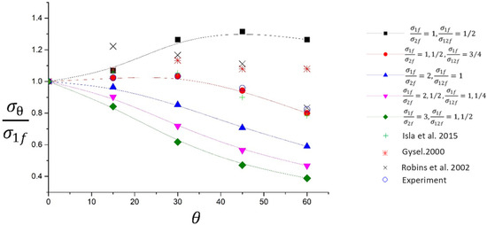
Figure 10.
Strength dependency of transversely isotropic fibre upon embedded orientation. Comparisons between Equation (3), experiment (o), and other published data [25,28,29].
Overlaid upon the five u. b. plots in Figure 10 are the available experimental data. The five upper bound predictions shown apply to their two strength ratios lying in the ranges: and. Overall, the experimental data mostly agrees with a strength ratio combination of and . For the new data (o), the reduction to upper bound strength at and beyond the 30° inclination angle was attributed to matrix spalling during the pull-out process. With the change from lower to upper bound, the fibre fails from having attained its off-axis combined strength under the applied force.
Considerably more experimental data [30] are available for aligned fibre where lower bound force/stress estimates apply to a complete pull-out. Further data [31,32,33] suggests that fibres will pull out when embedded with a slight misalignment to the force. In Figure 6, for example, the lower bound peak force attained was converted to a nominal stress and then normalised with the fibre’s axial tensile strength (see Equations (11) and (12)). The results (which include aligned fibre, θ = 0°) showed that the ultimate tensile strength of the fibre material was never reached under the peak load required to straighten the hook for a complete pull-out to occur. Therefore, the aligned fibre results indicate an intercept value of less than unity should be placed on the ordinate in Figure 10. This marks the start of the lower bound plot, which rises in proportion to 1/cosθ for a narrow orientation range. Here, Figure 6a–d show the range that applies to l. b. plots for four composites, where each aligned fibre–cement combination has a different intercept on the stress axis. Hence the intercepts for each u. b. plot depend on the fibre–cement combination. In contrast each u. b. plot in Figure 10 has a common intercept of unity at the UTS of the fibre.
It has been observed that the bounding approach relies on tensile and shear strength data obtained from the innovative testing methods proposed in this paper. In addition to providing data for pristine cementitious samples, as has been reported, so would the data from recycled composite constituents be found [34,35]. It is noted that the strengths of the fibre are dominant in presenting each failure bound, though creating a third bound for re-cycled concrete strength should account for a greater influence of spalling on fibre failure in these materials. The incidence of a deeper, wider cavity on a fracture surface around the entry position of a fibre would undoubtedly create plastic bending. The straightening of an inclined fibre through this action assists with the complete pull-out of the fibre before shank failure. It has been observed that shank failure is evident in the case of high-strength concrete with greater resistance to spalling.
This means that the spalling given is a direct consequence of the concrete’s weakness in tension. Pulling on an inclined fibre releases the bond within the region of concrete around the fibre, which is placed in tension from bending. The effect is to open a cavity on the free surface, which alters the fibre orientation angle locally. The bounding approach accounts for the uncertainty that spalling places on the initial orientation, as a transition from upper to lower bound may occur when spalling is severe in a weaker concrete mix.
5. Conclusions
- In this paper, a new bounding approach and associated novel testing methods have been developed to predict the pull-out response of misaligned hooked-end steel fibres embedded in a concrete matrix.
- An upper bound estimate of the pull-out strength is based upon a transversely isotropic failure condition that arises in the straight length of the inclined fibre shank. Therein, the bound accounts for the orientation and anisotropic strength properties of the deep-drawn fibre and the off-axis plane stress state that exists within its straight shank.
- The transversely isotropic failure criterion applies to deep-drawn wire, where grains are elongated through multiple reductions to achieve their final diameter. Metallography revealed that elongated grains, with an aspect ratio exceeding five, were aligned with the fibre’s length direction.
- Novel fibre strength tests have been proposed to measure the transverse and shear strengths required for positioning an upper bound limit curve in a plot of failure load versus fibre orientation.
- The lower bound limit is based on the complete pull-out of an aligned, hooked-end fibre embedded in a cementitious matrix. The peak force is that required to straighten the hook end. The experimental data are used to set the initial peak nominal stress (force/area) limit for an aligned fibre. For slightly inclined fibres, this stress increases, with it being inversely proportional to the cosine of the inclination angle. Normally, in a strong matrix, where spalling is absent, the lower bound mode is restricted to a range of 0–30°. Beyond this range, fibre failure occurs in the upper bound mode, where the shank undergoes necking.
- Where spalling occurs during pull-out, a lower bound range may be extended to allow the fibre to bend in closer to alignment with the pulling force. This applies, provided that such bending does not result in fibre breakage where then the bending has contributed to an upper bound failure, albeit with reduced orientation. To determine which failure mode spalling contributes to, it is suggested here that an additional intermediate bound be placed on the strength of the concrete mix in the interface region where spalling occurs.
- A comparison between the u. b. and l. b. modes of failure proposed here, and the division arising between them, has provided an explanation of all available experimental data thus far. Finally, the motivation for the present study was to account for the two failure modes observed in pull-out testing of misaligned hooked-end steel fibre. Such behaviour is relevant to concrete reinforcement with short fibres having random orientations, as seen in pre-cast concrete sections, such as tunnels and viaducts. Where loading is complex, a random fibre orientation ensures some alignment with varying principal stress directions. In contrast, the rebar method of reinforcement is restricted to alignment with the unvarying direction of maximum tension in beams and columns.
Author Contributions
Conceptualization, methodology formal analysis, writing—review and editing D.W.A.R.; validation; data curation, writing—original draft preparation; S.A. All authors have read and agreed to the published version of the manuscript.
Funding
This research received no external funding.
Data Availability Statement
All data are included within the paper.
Conflicts of Interest
The authors declare that they have no conflicts of interest.
References
- Domski, J.; Katzer, J.; Zakrzewski, M.; Ponikiewski, T. Comparison of the mechanical characteristics of engineered and waste steel fiber used as reinforcement for concrete. J. Clean. Prod. 2017, 158, 18–28. [Google Scholar] [CrossRef]
- Zīle, E.; Zīle, O. Effect of the fiber geometry on the pullout response of mechanically deformed steel fibers. Cem. Concr. Res. 2013, 44, 18–24. [Google Scholar] [CrossRef]
- Tai, Y.; El-Tawil, S. High loading-rate pullout behavior of inclined deformed steel fibers embedded in ultra-high performance concrete. Constr. Build. Mater. 2017, 148, 204–218. [Google Scholar] [CrossRef]
- Abdallah, S.; Fan, M. Anchorage mechanisms of novel geometrical hooked-end steel fibres. Mater. Struct. 2017, 50, 139. [Google Scholar] [CrossRef]
- Abdallah, S.; Fan, M.; Cashell, K.A. Bond-slip behaviour of steel fibres in concrete after exposure to elevated temperatures. Constr. Build. Mater. 2017, 140, 542–551. [Google Scholar] [CrossRef]
- Feng, J.; Sun, W.W.; Wang, X.M.; Shi, X.Y. Mechanical analyses of hooked fiber pullout performance in ultra-high-performance concrete. Constr. Build. Mater. 2014, 69, 403–410. [Google Scholar] [CrossRef]
- Abu-Lebdeh, T.; Hamoush, S.; Heard, W.; Zornig, B. Effect of matrix strength on pullout behavior of steel fiber reinforced very-high strength concrete composites. Constr. Build. Mater. 2011, 25, 39–46. [Google Scholar] [CrossRef]
- Tuyan, M.; Yazıcı, H. Pull-out behavior of single steel fiber from SIFCON matrix. Constr. Build. Mater. 2012, 35, 571–577. [Google Scholar] [CrossRef]
- Beglarigale, A.; Yazıcı, H. Pull-out behavior of steel fiber embedded in flowable RPC and ordinary mortar. Constr. Build. Mater. 2015, 75, 255–265. [Google Scholar] [CrossRef]
- Won, J.; Hong, B.; Lee, S.; Choi, S.J. Bonding properties of amorphous micro-steel fibre-reinforced cementitious composites. Compos. Struct. 2013, 102, 101–109. [Google Scholar] [CrossRef]
- Won, J.; Lee, J.; Lee, S. Bonding behaviour of arch-type steel fibres in a cementitious composite. Compos. Struct. 2015, 133, 117–123. [Google Scholar] [CrossRef]
- Abdallah, S.; Fan, M.; Zhou, X. Pull-Out Behaviour of Hooked End Steel Fibres Embedded in Ultra-high Performance Mortar with Various W/B Ratios. Int. J. Concr. Struct. Mater. 2017, 11, 301–313. [Google Scholar] [CrossRef]
- Abdallah, S.; Fan, M.; Rees, D.W.A. Effect of elevated temperature on pull-out behaviour of 4DH/5DH hooked end steel fibres. Compos. Struct. 2017, 165, 180–191. [Google Scholar] [CrossRef]
- Abrishambaf, A.; Barros, J.A.; Cunha, V.M.; Frazão, C. Time dependent behaviour of fibre pull-out in self-compacting concrete. Cem. Concr. Compos. 2017, 77, 14–28. [Google Scholar] [CrossRef]
- Georgiadi-Stefanidi, K.; Mistakidis, E.; Pantousa, D.; Zygomalas, M. Numerical modelling of the pull-out of hooked steel fibres from high-strength cementitious matrix, supplemented by experimental results. Constr. Build. Mater. 2010, 24, 2489–2506. [Google Scholar] [CrossRef]
- Chanvillard, G. Modeling the pullout of wire-drawn steel fibers. Cem. Concr. Res. 1999, 29, 1027–1037. [Google Scholar] [CrossRef]
- Alwan, J.M.; Naaman, A.E.; Guerrero, P. Effect of mechanical clamping on the pull-out response of hooked steel fibers embedded in cementitious matrices. Concr. Sci. Eng. 1999, 1, 15–25. [Google Scholar]
- Laranjeira, F.; Aguado, A.; Molins, C. Predicting the pullout response of inclined straight steel fibers. Mater. Struct. 2010, 43, 875–895. [Google Scholar] [CrossRef]
- Soetens, T.; Van Gysel, A.; Matthys, S.; Taerwe, L. A semi-analytical model to predict the pull-out behaviour of inclined hooked-end steel fibres. Constr. Build. Mater. 2013, 43, 253–265. [Google Scholar] [CrossRef]
- Lee, Y.; Kang, S.; Kim, J. Pullout behavior of inclined steel fiber in an ultra-high strength cementitious matrix. Constr. Build. Mater. 2010, 24, 2030–2041. [Google Scholar] [CrossRef]
- Laranjeira, F.; Molins, C.; Aguado, A. Predicting the pullout response of inclined hooked steel fibers. Cem. Concr. Res. 2010, 40, 1471–1487. [Google Scholar] [CrossRef]
- Zhan, Y.; Meschke, G. Analytical model for the pullout behavior of straight and hooked-end steel fibers. J. Eng. Mech. 2014, 140, 04014091. [Google Scholar] [CrossRef]
- Rees, D.W. Mechanics of Deformable Solids; Studium Press: Houston, TX, USA, 2012. [Google Scholar]
- Jones, R.M. Mechanics of Composite Materials; CRC Press: Boca Raton, FL, USA, 1998. [Google Scholar]
- Isla, F.; Ruano, G.; Luccioni, B. Analysis of steel fibers pull-out. Experimental study. Constr. Build. Mater. 2015, 100, 183–193. [Google Scholar] [CrossRef]
- Rees, D.W. Mechanics of Solids and Structures; World Scientific: Singapore, 2016. [Google Scholar]
- Rees, D.W. Mechanics of Elastic Solids; World Scientific: Singapore, 2018. [Google Scholar]
- Van Gysel, A. Studie van Het Uittrekgedrag van Staalvezels Ingebed in Een Cementgebonden Matrix Met Toepassing op Staalvezelbeton Onderworpen aan Buiging. Ph.D. Thesis, Ghent University, Gent, Belgium, 2000. [Google Scholar]
- Robins, P.; Austin, S.; Jones, P. Pull-out behaviour of hooked steel fibres. Mater. Struct. 2002, 35, 434–442. [Google Scholar] [CrossRef]
- Abdallah, S.; Fan, M.; Rees, D.W. Bonding Mechanisms and Strength of Steel Fiber–Reinforced Cementitious Composites: Overview. J. Mater. Civ. Eng. 2018, 30, 04018001. [Google Scholar] [CrossRef]
- Abdallah, S.; Fan, M.; Rees, D.W.A. Predicting pull-out behaviour of 4D/5D hooked end fibres embedded in normal-high strength concrete. Eng. Struct. 2018, 172, 967–980. [Google Scholar] [CrossRef]
- Ding, X.; Zhao, M.; Li, H.; Zhang, Y.; Liu, Y.; Zhao, S. Bond behaviors of steel fiber in mortar affected by inclination angle and fiber spacing. Materials 2022, 15, 6024. [Google Scholar] [CrossRef]
- MacGregor, J.G.; Wight, J.K.; Teng, S.; Irawan, P. Reinforced Concrete: Mechanics and Design; Prentice Hall: Upper Saddle River, NJ, USA, 1997. [Google Scholar]
- Wang, C.; Du, Z.; Zhang, Y.; Ma, Z. Elaborating the 3D microstructural characteristics and strength softening mechanical mechanism of fiber-reinforced recycled aggregate concrete. Constr. Build. Mater. 2024, 436, 137009. [Google Scholar] [CrossRef]
- Wang, C.; Guo, J.; Cao, L.; Zhang, Y.; Li, C.; Ma, Z. Mechanical behavior and fiber reinforcing mechanism of high-toughness recycled aggregate concrete under high strain-rate impact loads. Constr. Build. Mater. 2024, 437, 136960. [Google Scholar] [CrossRef]
Disclaimer/Publisher’s Note: The statements, opinions and data contained in all publications are solely those of the individual author(s) and contributor(s) and not of MDPI and/or the editor(s). MDPI and/or the editor(s) disclaim responsibility for any injury to people or property resulting from any ideas, methods, instructions or products referred to in the content. |
© 2024 by the authors. Licensee MDPI, Basel, Switzerland. This article is an open access article distributed under the terms and conditions of the Creative Commons Attribution (CC BY) license (https://creativecommons.org/licenses/by/4.0/).