Article

Identification of Effects of Parylene-C Coating on Electrospun Fibers

1
Department of Mechanical Engineering, Kyungpook National University, Daegu 41566, Republic of Korea
2
Daegu-Gyeongbuk Medical Innovation Foundation (K-MEDI hub), Daegu 41061, Republic of Korea
3
Institute of Mechanical Engineering Technology, Daegu 41566, Republic of Korea
4
ST1 Corp., Busan 46006, Republic of Korea
*
Author to whom correspondence should be addressed.
These authors contributed equally to this work.
Fibers 2024, 12(8), 69; https://doi.org/10.3390/fib12080069
Submission received: 12 July 2024 / Revised: 17 August 2024 / Accepted: 20 August 2024 / Published: 22 August 2024

Abstract

:
As various healthcare technologies such as regenerative medicine, precision medicine, and alternative approaches to animal testing develop, the interest in the use and application of nano- and microfibers is steadily increasing. In this study, the effect of parylene-C coating on electrospun fibers was investigated, and a pattern coating method was developed to expand the potential utilization of parylene-C-coated electrospun fibers. An SEM analysis demonstrated that parylene-C was successfully deposited on the electrospun fibers without any failure such as pinholes or air bubbles. Biocompatibility was investigated through cell tests, which indicated that the coated fibers were non-toxic and supported cell growth well. Tensile tests demonstrated a significant increase in the elastic modulus of the parylene-C-coated fibers, with it nearly quadrupling compared to the original PCL fibers, and the fracture strength almost doubled. At the same time, hydrophobicity was well maintained without any statistically significant changes. In particular, a non-adhesive magnet–metal masking was proposed in order to selectively coat the electrospun fibers with parylene-C with a specific pattern. Furthermore, it was presented that the magnet–metal mask-based coating electrospun nanofibers with parylene-C could be used in the fabrication of hybrid fibers composed of different diameters and materials.

1. Introduction

Electrospinning is a method of manufacturing continuous-phase fine fibers with diameters ranging from micro- (µm) to nanometers (nm) using an electric field. Electrospun fibers have been extensively studied across various fields since they were first reported by Zeleny in 1917 [1,2,3], owing to their advantages such as high volume-to-surface area ratio, porosity, and weak limitation in materials [4,5,6].
Electrospun nanofibers represent a versatile platform in biomedical applications, particularly in tissue engineering, regenerative medicine, and drug delivery [2,3,5,7,8]. In tissue engineering, these fibers emulate the human extracellular matrix, promoting cellular adhesion, proliferation, and differentiation, thereby supporting tissue regeneration and repair [9]. In regenerative medicine, electrospun fibers serve as matrices that promote cellular infiltration and tissue integration, aiding in wound healing by facilitating controlled release of growth factors and bioactive molecules to expedite healing processes and improve wound closure [8,10,11]. Moreover, in drug delivery systems these nanofibers offer precise control over drug release kinetics, minimizing systemic side effects and optimizing therapeutic outcomes by encapsulating drugs within the polymer matrix or incorporating them into coatings for targeted and sustained delivery at specific sites [12,13]. Despite their beneficial properties, the weak mechanical properties of electrospun fibers pose challenges in load-bearing applications and surgical implants [14,15]. Overcoming these limitations while maintaining biocompatibility remains pivotal for advancing electrospinning technologies towards clinical applications.
In recent years, parylene-C has garnered significant attention as a coating material for enhancing the properties of various substrates, particularly in biomedical applications. As a type of para-xylylene polymer, parylene-C possesses characteristics such as biostability, biocompatibility, moisture resistance, chemical resistance, corrosion resistance, and electrical insulation [16,17]. These properties make parylene-C especially suitable for applications where long-term stability and compatibility with biological tissues are critical. Furthermore, parylene-C’s FDA approval reinforces its compliance with rigorous medical safety standards, further justifying its selection for research in healthcare-related fields. Parylene-C has been effectively employed in several biomedical applications. For instance, parylene-C has been used to coat electrospun nanofibers in transdermal drug delivery systems, where it successfully modulates drug release kinetics. This coating prevents the burst release of hydrophilic drugs like pramipexole, providing a sustained release profile that is advantageous for targeted drug delivery applications [18]. Additionally, parylene-C has been utilized as a water vapor barrier in micropackaging technologies for implantable biomedical devices, significantly enhancing the longevity and reliability of these devices under harsh environmental conditions [19]. Moreover, the coating of stainless steel 316 L, a material commonly used in medical implants, with parylene-C has been shown to improve both its mechanical and protective properties by reducing metal ion release and enhancing corrosion resistance [20]. This protective quality is further evidenced in studies on implantable electrodes, where parylene-C coatings have been utilized to improve biocompatibility and bio-insulation, crucial factors for the long-term stability of medical devices [21]. The versatility of parylene-C extends beyond its use in standard coating applications. Research has demonstrated its effectiveness in creating hybrid coatings by combining parylene-C with other materials, such as aluminum, to enhance barrier properties and mechanical performance, thereby broadening its utility in various biomedical contexts [22]. The optimization of parylene-C and parylene-N thin films for biomedical implants has further underscored the superior mechanical properties and stability of parylene-C under physiological conditions [23]. Additionally, both in vitro and in vivo studies have confirmed the long-term durability of parylene-C as a coating material for chronically implanted devices, solidifying its status as a viable candidate for future biomedical applications [24]. Given these demonstrated benefits, previous studies have highlighted the utility of parylene-C in enhancing the mechanical properties and surface characteristics of different materials, making it an ideal candidate for addressing the inherent limitations of electrospun fibers. Notably, parylene-C is not only widely used in industrial applications but is also expected to see increased usage in the medical industry due to its cost effectiveness and widespread availability [25,26,27]. This study, therefore, aims to explore the effects of parylene-C coating on electrospun fibers and to develop a pattern coating method that could potentially expand the application of parylene-C-coated electrospun fibers in biomedical fields.
Here, it is shown that the properties of electrospun polycaprolactone (PCL) nanofibers can be improved through coating with parylene-C, and a process to selectively coat parylene-C is proposed to enhance its applicability. It is demonstrated that uniform and stable coating of electrospun nano- and microfibers with parylene-C through the CVD process can be achieved without pinholes or air bubbles. Additionally, various properties of parylene-C-coated electrospun fibers are investigated using an SEM analysis, contact angle measurement, mechanical properties tests, and live/dead feasibility assays. Considering the characteristics of electrospun fibers, which cannot be masked by conventional methods using adhesive masks or PR masks, a parylene-C pattern coating technique based on a magnet–metal masking is presented. Based on the parylene-C pattern coating, hybrid fibers composed of different diameters and materials can be fabricated, wherein nanofibers and microfibers coexist within a single fiber mesh. By employing this approach, we aimed to strategically incorporate the advantages of parylene-C coating, such as enhanced mechanical properties, moisture resistance, chemical resistance, corrosion resistance, and barrier properties, into specific locations within the electrospun fiber meshes. This method optimizes the overall functionality of the hybrid structures. Consequently, it is demonstrated that by depositing parylene-C, an FDA-approved material ensuring biological safety as per ISO 10993 [28], onto electrospun fibers, it not only addresses the limitations of conventional electrospun fibers but also introduces additional functionalities.

2. Materials and Methods

2.1. Electrospun Nano- and Microfibers

In this study, nanofibers and microfibers were obtained from Artipore (NNF84-LR30N00, MIF84-LR60N00, ST1 Corp., Busan, Republic of Korea). These nano- and microfibers were made of polycaprolactone (PCL) and were fabricated using a conventional solution-electrospinning process. According to the manufacturer, PCL mixed with chloroform (CF) and dimethylformamide (DMF) was used to manufacture nano- and microfibers through electrospinning. For electrospinning the nanofibers, a mixture of chloroform and dimethyl fluoride was used as the solvent, while chloroform alone was used as the solvent for electrospinning the microfibers. Both the nano- and microfibers were unaligned types, with a thickness of about 60 µm.

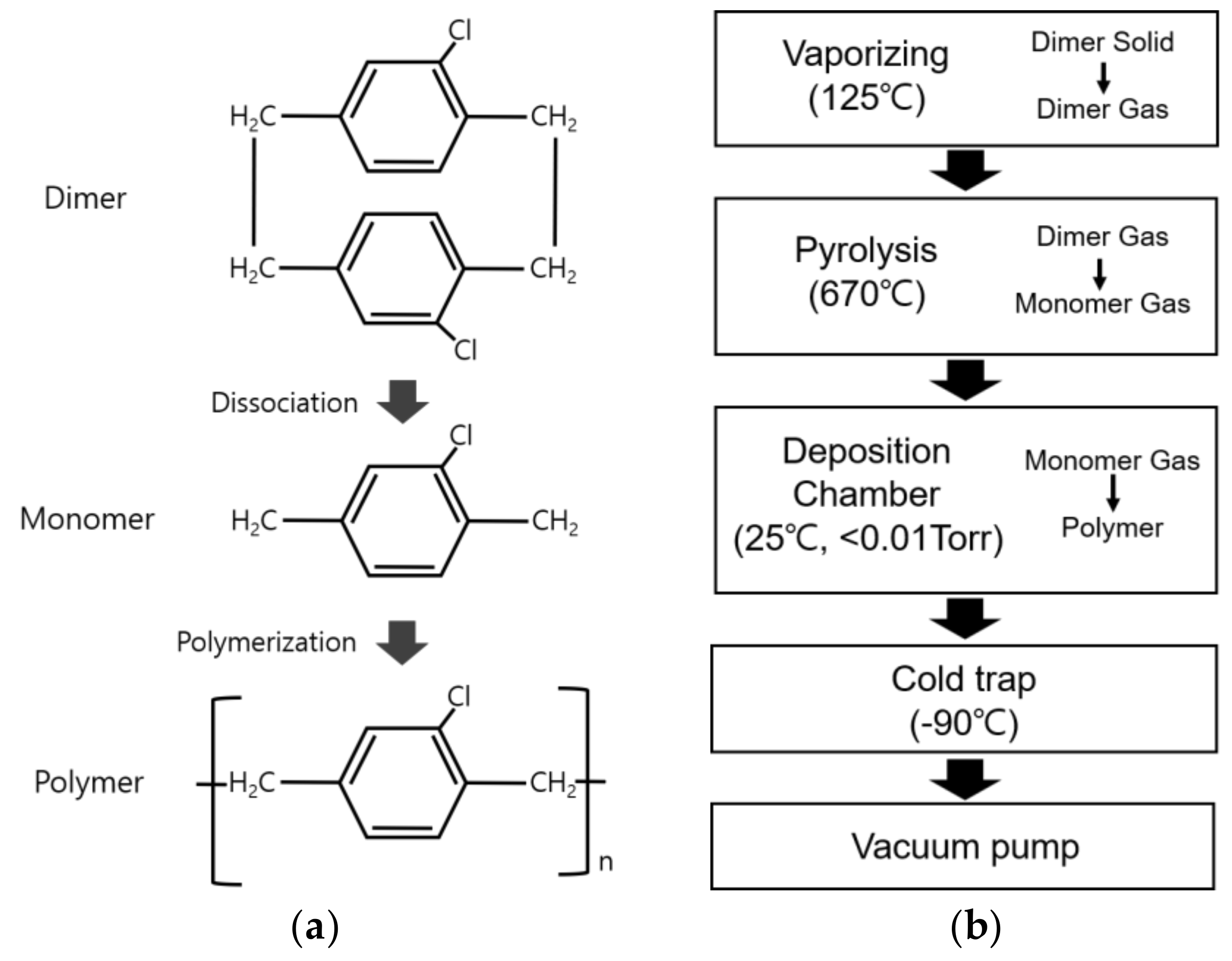
2.2. Parylene-C Coating Process

In the chemical vapor deposition (CVD) method employed for depositing a parylene-C thin layer, the parylene-C dimer (CAS NO. 28804-46-8, SCS, Indianapolis, IN, USA), with a molecular weight of 277.193 g/mol, in powder form dissociates into monomer molecules at the nanometer scale, facilitating the uniform coating of substrates such as electrospun fibers without pinholes or air bubbles [29,30]. Thus, it was concluded that fine structures such as electrospun nano- and microfibers could be uniformly coated with parylene-C (Figure 1a) [17].
Figure 1b illustrates the parylene-C coating process employed in this study. The process conditions are for a deposition thickness of about 500 nm. The coating process began with vaporizing 2.1 g of parylene-C powder in a chamber maintained at a pressure of 0.01 Torr or lower. The parylene-C dimer molecules dissociated into monomers at 670 °C in an electric furnace, followed by the coating of parylene-C in a vacuum chamber (<0.01 Torr) at room temperature. Finally, it was observed that all parylene-C raw materials were exhausted when the pressure in the vacuum chamber remained below 0.0056 Torr for 60 min or longer (Nuritech, Incheon, Republic of Korea).

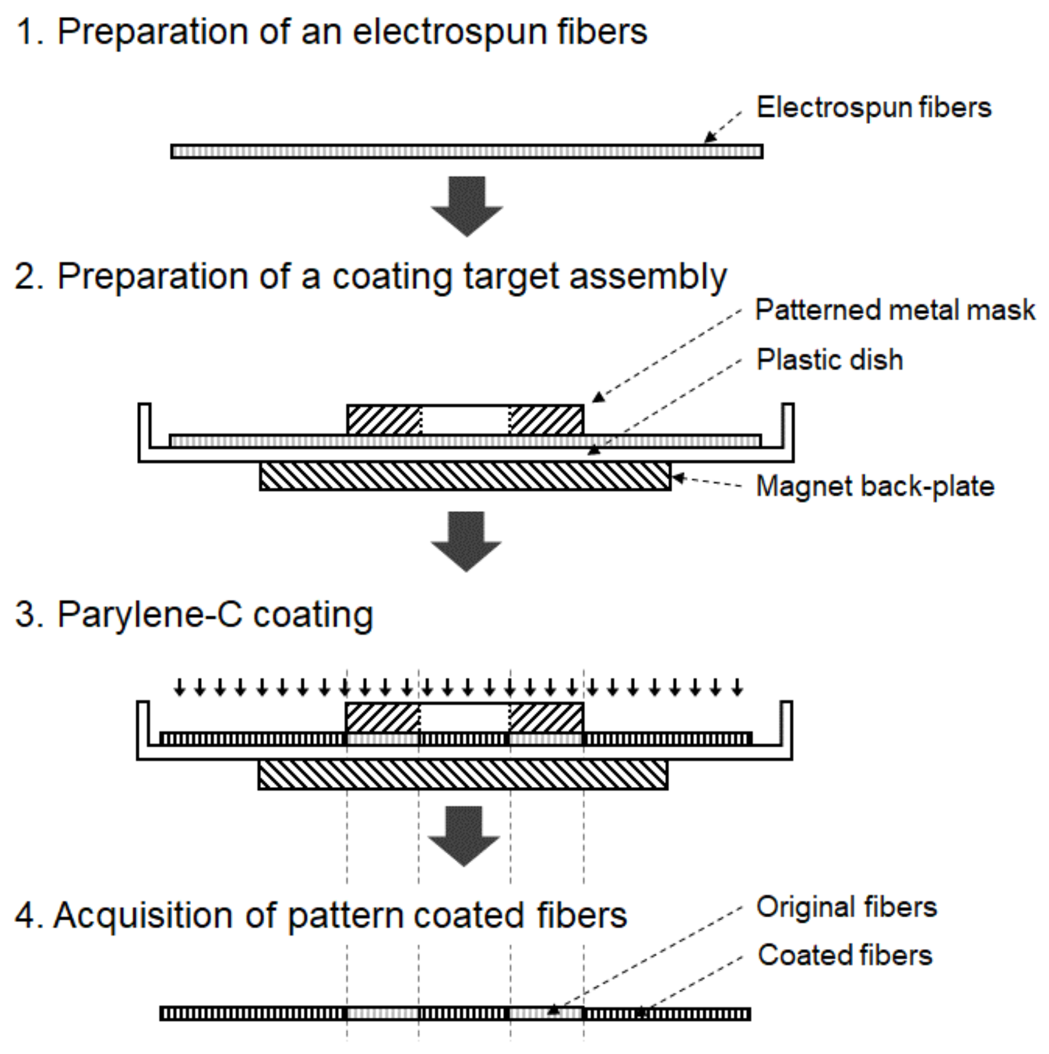
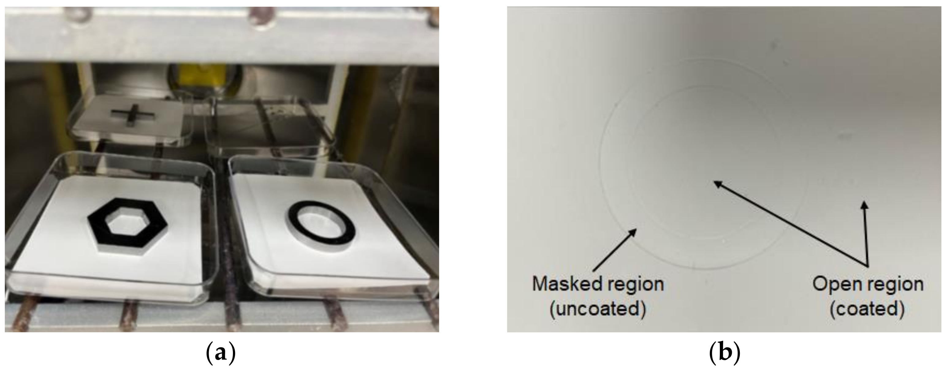
2.3. Pattern Coating of Parylene-C

Conventional pattern coating methods utilizing adhesive or photo-resist (PR) masks can potentially cause damage to nano- or microfibers. Therefore, in this study, a novel method for masking electrospun fibers using a magnet back-plate and a patterned metal mask was developed. Electrospun fibers are clamped between a magnet back-plate and a patterned metal mask, which are placed in a vacuum chamber, followed by parylene-C coating. Figure 2 shows the schematic diagram of the parylene-C pattern coating procedure for electrospun fibers with the help of magnet–metal masking.
A metal mask was designed according to the desired shape using 3D CAD (SolidWorks, Dassault Systemes, Vélizy-Villacoublay, France). S45C steel, chosen for its magnetic properties and ease of CNC machining, was selected as the mask material. Machining was performed using a machining center (Doosan, Changwon, Republic of Korea). The machined metal mask was positioned over the fibers within a vacuum chamber, with a neodymium magnet back-plate placed underneath to secure both the metal mask and the electrospun fibers. Subsequently, a thin layer of parylene-C was deposited on the fibers.

2.4. Morphology and Surface Properties Analyses

The morphology of the prepared samples was investigated using a field-emission scanning electron microscope (FE-SEM, Hitachi, Tokyo, Japan). All the specimens were coated with platinum using ion sputtering, and images were captured at acceleration voltages ranging from 5.0 kV to 10.0 kV, with magnifications up to 10,000×. The dimensions of the nano- and microfibers were measured using the ImageJ software (National Institutes of Health, Bethesda, MD, USA) based on the acquired SEM images.
The effect of parylene-C coating on electrospun PCL fibers was investigated by measuring the water contact angles of the original and parylene-C-coated electrospun microfibers using a water contact angle tester (Femtobiomed Inc., Seongnam, Republic of Korea). The water contact angle between a water droplet and its substrate surface can be expressed using Young’s equation, as shown in Equation (1).
γsv = γ cosθ + γsl
where θ is the water contact angle; γsv and γsl are the solid–vapor and solid–liquid interfacial tensions, respectively, and γ is the surface tension of the liquid [31]. Generally, solid surfaces with high surface energy are hydrophilic and exhibit low water contact angles, while solid surfaces with low surface energy are hydrophobic and exhibit high contact angles [32].

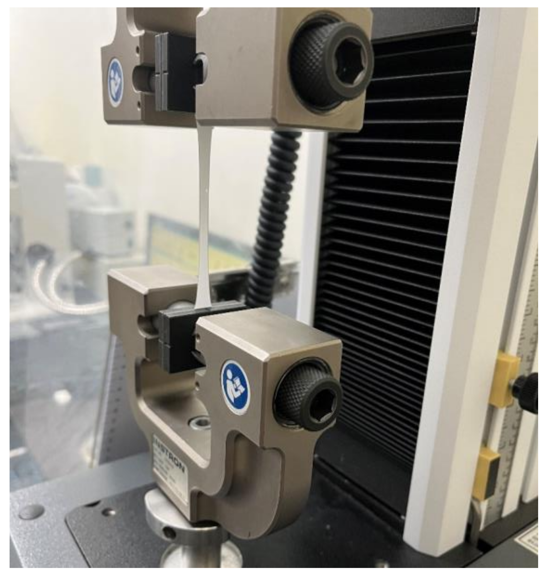
2.5. Mechanical Properties Analyses

To identify the mechanical properties of the original PCL electrospun microfibers and the parylene-C-coated ones, tensile tests were carried out using a universal testing machine (Instron Corp., Norwood, MA, USA) (Figure 3). Fiber mesh samples were cut to a gauge length of 50 mm and a gauge width of 10 mm. The tensile test was performed three times at a crosshead speed of 5 mm/min, and then, the stress–strain curves and elastic moduli were calculated from the force–displacement data obtained.

2.6. Cell Viability Test

To assess the cytotoxicity of the original and parylene-C-coated PCL electrospun microfibers, cell viability was experimentally evaluated using mouse fibroblast cells (NIH3T3, Korean Cell Line Bank, Seoul, Republic of Korea). Cells were cultured in an incubator with 5% CO2, supplemented with 10% fetal bovine serum (FBS, Invitrogen, Carlsbad, CA, USA) and 1% penicillin–streptomycin (P/S, Invitrogen, Carlsbad, CA, USA) in α-MEM cell culture medium.
The fibers were cut into 10 × 12 mm pieces, placed on a 6-well cell culture slide (SPL Life Sciences, Pocheon, Republic of Korea), immersed in 70% ethanol for 30 min, washed three times with phosphate-buffered saline (PBS, Invitrogen, Carlsbad, CA, USA), and sterilized by UV irradiation for 1 h. Cells were seeded onto the cut fibers at a density of 4 × 10⁴ cells/sample and cultured for 24 h to allow for cell adhesion, and cell viability was assessed using a live/dead cell assay kit (Invitrogen, Carlsbad, CA, USA). Living cells were stained green while dead cells were stained red, and these were observed using a confocal laser scanning microscope (Carl Zeiss, Oberkochen, Germany).

3. Results and Discussion

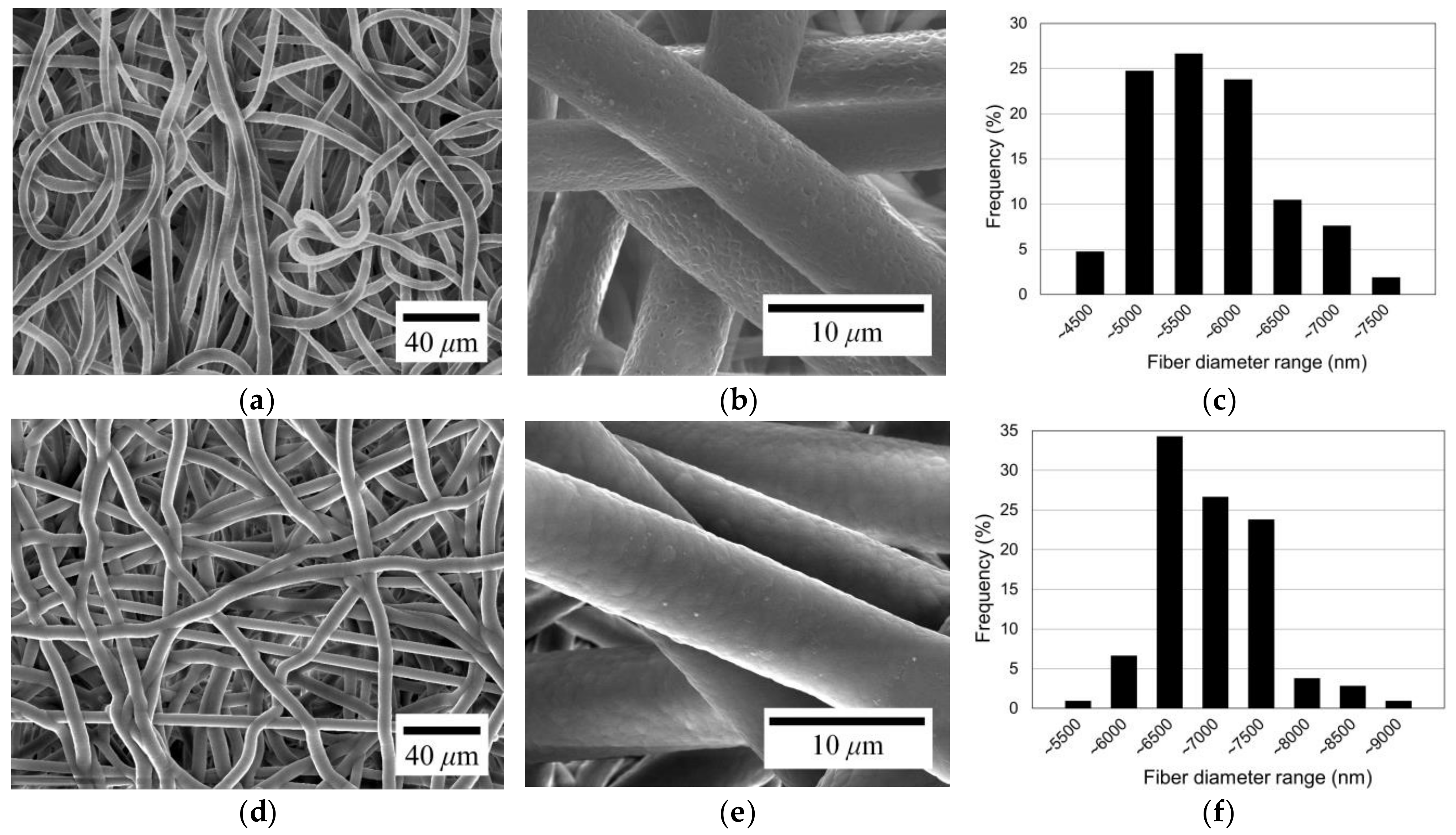
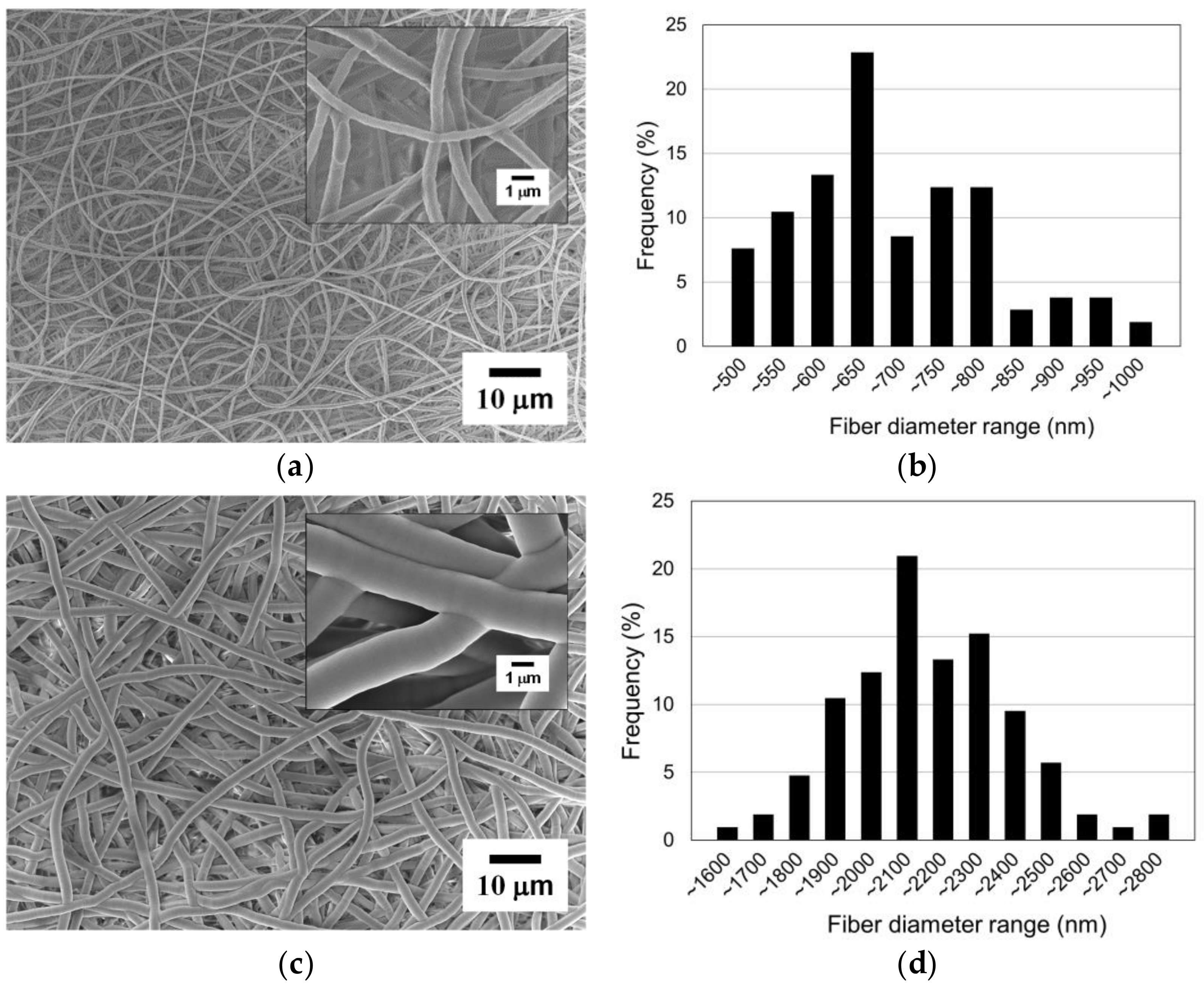
3.1. Morphological Properties

To investigate the morphological change after coating, electrospun microfibers with a diameter of about 5.5 µm were coated with parylene-C. The original electrospun microfibers, depicted in Figure 4a,b, exhibit the typical morphology of general electrospun microfibers. The fibers have a slight curl/buckling formation. Also, it can be seen from the figures that the original microfibers have a relatively rough surface. Figure 4c illustrates the diameter distribution of the electrospun fibers shown in Figure 4a. The fiber diameters range from about 4.0 to 7.5 µm, with the most frequent diameter falling within the 5.0 to 5.5 µm range. The mean diameter is 5.45 µm, and the standard deviation is 0.67 µm, which corresponds to 12.35% of the mean diameter, indicating a high degree of diameter uniformity among the fibers.
Figure 4d presents the SEM image of the microfibers after parylene-C coating, showing a slight increase in fiber diameter without a change in shape. However, the fiber surface has changed to a smooth texture, as shown in Figure 4e. It can be seen that parylene-C was successfully coated onto the fiber surface. The diameter distribution of the parylene-C-coated fibers is illustrated in Figure 4f. The diameter range of the parylene-C-coated fibers is between about 5.0 and 9.0 µm, with the most frequent diameters falling within the 6.0 to 6.5 µm range. The average diameter is 6.73 µm, with a standard deviation of 0.61 µm, which is 9.04% of the mean diameter. There is no significant change in the diameter deviation level of parylene-C-coated fibers from the original ones. Therefore, it can be seen that the fibers were uniformly coated with parylene-C.
Figure 5 shows a comparison in fiber diameter between the original and the parylene-C-coated electrospun PCL microfibers. As shown in the figure, the statistically meaningful difference in average diameters of original and parylene-C-coated fibers is 1.28 µm with a p-value less than 0.001, implying that the parylene-C coating thickness was about 630 nm. Consequently, although the initial design intended for a 500 nm thick parylene-C coating, it was determined that the parylene-C was uniformly applied to the fibers with a thickness of approximately 630 nm, indicating a minor deviation.

3.2. Water Contact Angles

Surface property modification through parylene-C coating was investigated via the water contact angle measurement, which was repeated five times for accuracy. The average water contact angle of the original PCL electrospun microfibers was 128.1° with a standard deviation of 8.27°, whereas the parylene-C-coated microfibers exhibited a contact angle of 134.2° with a standard deviation of 1.48° (Figure 6). It can be seen that the hydrophobic properties of the PCL microfibers were slightly but not significantly enhanced via the parylene-C coating despite PCL being inherently hydrophobic. Therefore, it can be concluded that parylene-C coating in this study did not significantly affect the hydrophobicity of the PCL microfibers.

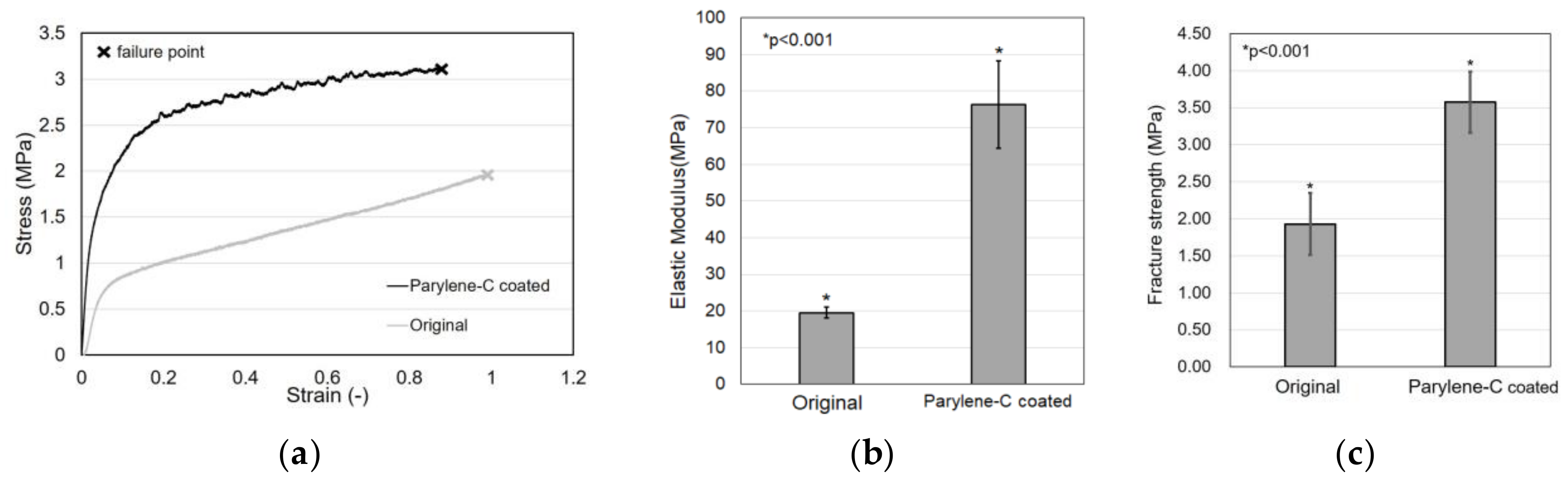
3.3. Mechanical Properties
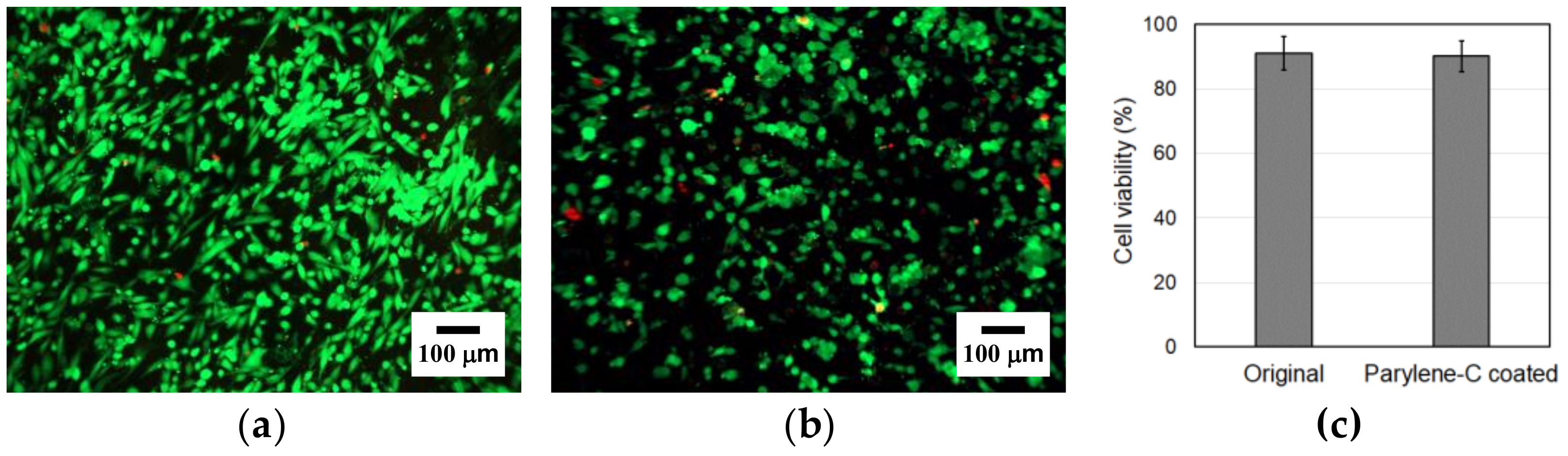
Tensile tests were carried out to evaluate the effect of parylene-C coating on electrospun PCL microfibers. Figure 7a shows the stress–strain curves of the original and the parylene-C-coated electrospun PCL microfibers, which shows that the parylene-C coating improved the mechanical properties of the electrospun PCL microfibers. However, the property of strain at break looks slightly reduced.
In particular, the elastic modulus of the original PCL microfiber meshes was 19.52 MPa, whereas the parylene-C-coated microfiber meshes exhibited an elastic modulus of 76.21 MPa, demonstrating a dramatic increase of about four times (Figure 7b). Additionally, Figure 7c shows that the fracture strength of the original microfiber meshes was 1.93 MPa, whereas the fracture strength of the parylene-C-coated microfiber meshes was 3.58 MPa. These results indicate that parylene-C coating can significantly enhance the mechanical properties of electrospun microfibers without causing significant changes in their morphology, except for their diameter.

3.4. Cytotoxicity

To investigate the impact of parylene-C coating on the cytotoxicity of PCL microfibers, a live/dead cell assay was carried out. The results demonstrated high cell viability with minimal cell death in both types of microfibers (Figure 8a,b). Additionally, we observed a higher number of cells on the original microfibers, suggesting that the parylene-C coating on the microfibers might cause a slight deterioration in cell adhesion.
Among the cells attached to the original and the parylene-C-coated PCL electrospun microfibers, 91.05% and 90.11% were live cells, respectively (Figure 8c). The difference in the percentage of live cells between the original and parylene-C-coated PCL electrospun microfibers is negligible and not statistically meaningful. Therefore, it can be concluded that the parylene-C coating does not cause a deterioration in the cell viability of the electrospun PCL microfibers. Moreover, stable cell settlement could be observed even 24 h after seeding, demonstrating excellent cell adhesion quality in both the original and the parylene-C-coated electrospun PCL microfibers.

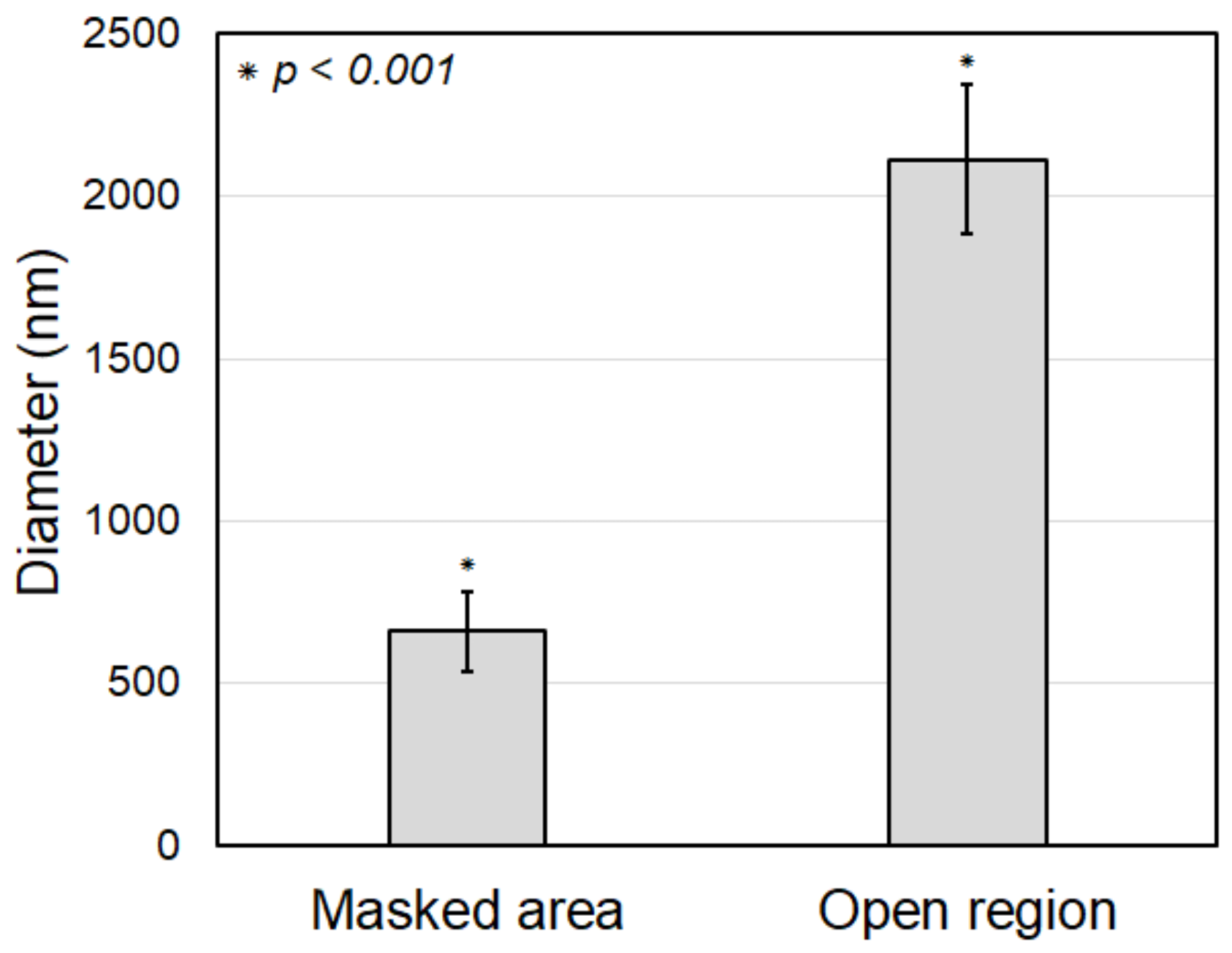
3.5. Fabrication of Hybrid Fiber Meshes via Parylene-C Pattern Coating

The feasibility of parylene-C pattern coating on electrospun fibers was experimentally evaluated, and its applicability in fabricating hybrid fiber meshes composed of nano- and microfibers was also investigated. For this purpose, electrospun PCL nanofibers were used as the coating target. Moreover, 4.2 g of parylene-C powder was vaporized to achieve a coating thickness of about 1 µm. Consequently, the coated nanofibers became thicker fibers, with a diameter greater than 2 µm, while the diameter of the original nanofibers under the mask remained at its original value of several hundred nanometers. A torus-shaped metal mask was used, as shown in Figure 9a.
Figure 9b shows the electrospun PCL nanofibers after parylene-C coating. In the obtained sample, compression traces can be seen in the area that was clipped with the mask. It was confirmed that the compression trace had the same shape and size as the mask because the compression was nearly uniform and strong enough. However, aside from the compression marks, it was difficult to visually discern any difference in color or surface properties between the fibers in the masked and open regions.
Figure 10a shows an SEM image of the PCL nanofibers covered with the mask (i.e., the masked region). It was difficult to find any clear damage or deformation on the nanofibers induced by the masking process. Therefore, it can be seen that the masking method did not significantly affect the nanofiber morphology or quality. Meanwhile, Figure 10c shows an SEM image of the parylene-C-coated nanofibers in the open region. The surface of the parylene-C-coated nanofibers was smoother compared to the original nanofibers, and their diameter increased significantly to the micrometer scale. Moreover, strong interconnectivity between the fibers was achieved through the thick coating of parylene-C.
The original electrospun PCL nanofibers in the masked region, without parylene-C coating, have diameters between 450 and 1000 nm, with an average diameter of 661.09 nm and a standard deviation of 122.23 nm, as shown in Figure 10b. It can be observed that the nanofibers were electrospun with a relatively uniform diameter. The parylene-C-coated electrospun microfibers in the open region have diameters between 1500 and 2800 nm, with an average diameter of 2113.42 nm and a standard deviation of 229.16 nm, as shown in Figure 10d. This demonstrates that all nanofibers in the open region were uniformly coated with a thick parylene-C layer, unlike the nanofibers in the masked region. The difference in average fiber diameter between the coated and the uncoated fibers is about 1452.33 nm (Figure 11). As previously mentioned, this experiment was performed under conditions for a 1000 nm thick parylene-C coating. However, there was a 14% increase, not a 100% increase, compared to the diameter difference of 1275 nm shown in Figure 5, which was performed under conditions for a 500 nm thick parylene-C coating. These results indicate that the parylene-C coating of electrospun nanofibers is less efficient than that of microfibers. This is presumed to be due to the increase in surface area caused by the high porosity and large pore size of nanofibers. Nevertheless, the experiment demonstrated that the electrospun nanofibers could be selectively coated with parylene-C through the proposed magnet–metal masking, and a hybrid fiber structure in which nanofibers and microfibers coexist in distinct sections within a single structure was successfully produced.

4. Conclusions

In this study, the effects of parylene-C coating on PCL electrospun fibers were investigated, and a pattern coating method was developed to expand the potential utilization of parylene-C-coated electrospun fibers. An SEM analysis revealed that parylene-C was uniformly coated on electrospun microfibers without any pinholes or air bubbles, resulting in a smooth surface. The mechanical properties were significantly enhanced, with the elastic modulus of parylene-C-coated microfibers increasing to 76.21 MPa compared to 19.52 MPa for the original microfibers. It was shown that the hydrophobicity of PCL microfibers was well maintained or slightly improved through parylene-C coating. In terms of cell viability, the live/dead assay demonstrated high cell viability with minimal cell death for both the original and parylene-C-coated microfibers. In detail, 91.05% of cells on the original microfibers and 90.11% on the coated microfibers were live, indicating no significant cytotoxicity due to the coating. Additionally, a novel magnet–metal masking technique was introduced to the coating process and it enabled precise parylene-C pattern coating on electrospun fibers without damaging the fiber structure, suggesting potential applications in creating hybrid fiber structures in which nanofibers and microfibers coexist in distinct sections within a single structure. The electrospun fibers with the patterned parylene-C thin film developed in this study are expected to be further advanced as a wound covering or drug delivery device capable of targeting specific local areas within single fiber meshes through various drug loading and in vivo evaluations. Additionally, it is anticipated that this development will address the major limitations of existing electrospinning fibers by enhancing their mechanical properties, thereby enabling their use as implantable scaffolds or wearable devices that require load-bearing capabilities.

Author Contributions

Conceptualization, Y.H.J. and T.-H.S.; methodology, T.-H.S., D.-G.K. and J.H.K.; validation, Y.H.J.; investigation, T.-H.S., J.R. and J.H.K.; resources, Y.H.J. and J.R.; data curation, T.-H.S. and J.H.K.; writing—original draft preparation, T.-H.S. and J.H.K.; writing—review and editing, Y.H.J., T.-H.S. and J.H.K.; supervision, Y.H.J.; project administration, Y.H.J.; funding acquisition, Y.H.J. and T.-H.S. All authors have read and agreed to the published version of the manuscript.

Funding

This work was supported by the Ministry of Trade, Industry and Energy (MOTIE) and Korea Institute for Advancement of Technology (KIAT) through the Industrial Technology Innovation Program (Project No. P0025996) and the National Research Foundation of Korea (NRF) grant funded by the Korea government (MSIT) (No. 2021R1A2C2014364).

Data Availability Statement

The datasets used and/or analysed during the current study are available from the corresponding author on reasonable request.

Conflicts of Interest

Young Hun Jeong is employed by ST1 Corp.

References

  1. Zeleny, J. The electrical discharge from liquid points, and a hydrostatic method of measuring the electric intensity at their surfaces. Phys. Rev. 1914, 3, 69. [Google Scholar] [CrossRef]
  2. Li, D.; Xia, Y. Electrospinning of nanofibers: Reinventing the wheel? Adv. Mater. 2004, 16, 1151–1170. [Google Scholar] [CrossRef]
  3. Pham, Q.P.; Sharma, U.; Mikos, A.G. Electrospinning of polymeric nanofibers for tissue engineering applications: A review. Tissue Eng. 2006, 12, 1197–1211. [Google Scholar] [CrossRef]
  4. Abd Razak, S.I.; Wahab, I.F.; Fadil, F.; Dahli, F.N.; Md Khudzari, A.Z.; Adeli, H. A review of electrospun conductive polyaniline based nanofiber composites and blends: Processing features, applications, and future directions. Adv. Mater. Sci. Eng. 2015, 2015, 356286. [Google Scholar] [CrossRef]
  5. Sattary, M.; Rafienia, M.; Khorasani, M.T.; Salehi, H. The effect of collector type on the physical, chemical, and biological properties of polycaprolactone/gelatin/nano-hydroxyapatite electrospun scaffold. J. Biomed. Mater. Res. Part B Appl. Biomater. 2019, 107, 933–950. [Google Scholar] [CrossRef]
  6. Arroyo-Reyes, B.L.; Gómez-Muñoz, C.L.; Zaca-Morán, P.; Galindo-Ramírez, F.; Morales-Sánchez, M.A. Fabrication of a PLA/PVA-BIO-HA Polymeric Membrane by the Electrospinning Technique. Fibers 2024, 12, 33. [Google Scholar] [CrossRef]
  7. Bambole, V.; Yakhmi, J.V. Tissue engineering: Use of electrospinning technique for recreating physiological functions. In Nanobiomaterials in Soft Tissue Engineering; Elsevier: Amsterdam, The Netherlands, 2016; pp. 387–455. [Google Scholar]
  8. Sill, T.J.; Von Recum, H.A. Electrospinning: Applications in drug delivery and tissue engineering. Biomaterials 2008, 29, 1989–2006. [Google Scholar] [CrossRef]
  9. Sell, S.; Barnes, C.; Smith, M.; McClure, M.; Madurantakam, P.; Grant, J.; Mcmanus, M.; Bowlin, G. Extracellular matrix regenerated: Tissue engineering via electrospun biomimetic nanofibers. Polym. Int. 2007, 56, 1349–1360. [Google Scholar] [CrossRef]
  10. Norouzi, M.; Nazari, B.; Miller, D.W. Injectable hydrogel-based drug delivery systems for local cancer therapy. Drug Discov. Today 2016, 21, 1835–1849. [Google Scholar] [CrossRef]
  11. Dolgin, J.; Hanumantharao, S.N.; Farias, S.; Simon, C.G., Jr.; Rao, S. Mechanical properties and morphological alterations in fiber-based scaffolds affecting tissue engineering outcomes. Fibers 2023, 11, 39. [Google Scholar] [CrossRef]
  12. Kenawy, E.-R.; Bowlin, G.L.; Mansfield, K.; Layman, J.; Simpson, D.G.; Sanders, E.H.; Wnek, G.E. Release of tetracycline hydrochloride from electrospun poly (ethylene-co-vinylacetate), poly (lactic acid), and a blend. J. Control. Release 2002, 81, 57–64. [Google Scholar] [CrossRef]
  13. Zhang, Y.; Ouyang, H.; Lim, C.T.; Ramakrishna, S.; Huang, Z.M. Electrospinning of gelatin fibers and gelatin/PCL composite fibrous scaffolds. J. Biomed. Mater. Res. Part B Appl. Biomater. Off. J. Soc. Biomater. Jpn. Soc. Biomater. Aust. Soc. Biomater. Korean Soc. Biomater. 2005, 72, 156–165. [Google Scholar] [CrossRef] [PubMed]
  14. Sell, S.A.; McClure, M.J.; Garg, K.; Wolfe, P.S.; Bowlin, G.L. Electrospinning of collagen/biopolymers for regenerative medicine and cardiovascular tissue engineering. Adv. Drug Deliv. Rev. 2009, 61, 1007–1019. [Google Scholar] [CrossRef] [PubMed]
  15. Zulkifli, M.Z.A.; Nordin, D.; Shaari, N.; Kamarudin, S.K. Overview of Electrospinning for Tissue Engineering Applications. Polymers 2023, 15, 2418. [Google Scholar] [CrossRef] [PubMed]
  16. Von Metzen, R.P.; Stieglitz, T. The effects of annealing on mechanical, chemical, and physical properties and structural stability of Parylene C. Biomed. Microdevices 2013, 15, 727–735. [Google Scholar] [CrossRef]
  17. Ortigoza-Diaz, J.; Scholten, K.; Larson, C.; Cobo, A.; Hudson, T.; Yoo, J.; Baldwin, A.; Weltman Hirschberg, A.; Meng, E. Techniques and considerations in the microfabrication of Parylene C microelectromechanical systems. Micromachines 2018, 9, 422. [Google Scholar] [CrossRef]
  18. Tort, S.; Han, D.; Frantz, E.; Steckl, A.J. Controlled drug release of parylene-coated pramipexole nanofibers for transdermal applications. Surf. Coat. Technol. 2021, 409, 126831. [Google Scholar] [CrossRef]
  19. Kuo, H.-I.; Zhang, R.; Ko, W.H. Development of micropackage technology for biomedical implantable microdevices using parylene C as water vapor barrier coatings. In Proceedings of the SENSORS, 2010 IEEE, Waikoloa, HI, USA, 1–4 November 2010; pp. 438–441. [Google Scholar]
  20. Cieślik, M.; Kot, M.; Reczyński, W.; Engvall, K.; Rakowski, W.; Kotarba, A. Parylene coatings on stainless steel 316L surface for medical applications—Mechanical and protective properties. Mater. Sci. Eng. C 2012, 32, 31–35. [Google Scholar] [CrossRef] [PubMed]
  21. Lin, C.-Y.; Lou, W.-S.; Chen, J.-C.; Weng, K.-Y.; Shih, M.-C.; Hung, Y.-W.; Chen, Z.-Y.; Wang, M.-C. Bio-Compatibility and Bio-insulation of implantable electrode prosthesis ameliorated by A-174 Silane Primed Parylene-C deposited embedment. Micromachines 2020, 11, 1064. [Google Scholar] [CrossRef]
  22. Sethi, J.; Glowacki, E.; Reid, M.S.; Larsson, P.A.; Wågberg, L. Ultra-thin parylene-aluminium hybrid coatings on nanocellulose films to resist water sensitivity. Carbohydr. Polym. 2024, 323, 121365. [Google Scholar] [CrossRef]
  23. Gholizadeh, S.; Lincoln, D.M.; Allahyari, Z.; Widom, L.P.; Carter, R.N.; Gaborski, T.R. Optimization of Parylene C and Parylene N thin films for use in cellular co-culture and tissue barrier models. Sci. Rep. 2023, 13, 4262. [Google Scholar]
  24. Lecomte, A.; Degache, A.; Descamps, E.; Dahan, L.; Bergaud, C. In vitro and in vivo biostability assessment of chronically-implanted Parylene C neural sensors. Sens. Actuators B Chem. 2017, 251, 1001–1008. [Google Scholar] [CrossRef]
  25. Golda-Cepa, M.; Engvall, K.; Hakkarainen, M.; Kotarba, A. Recent progress on parylene C polymer for biomedical applications: A review. Prog. Org. Coat. 2020, 140, 105493. [Google Scholar] [CrossRef]
  26. Chang, T.Y.; Yadav, V.G.; De Leo, S.; Mohedas, A.; Rajalingam, B.; Chen, C.-L.; Selvarasah, S.; Dokmeci, M.R.; Khademhosseini, A. Cell and protein compatibility of parylene-C surfaces. Langmuir 2007, 23, 11718–11725. [Google Scholar] [CrossRef]
  27. Song, J.S.; Lee, S.; Jung, S.H.; Cha, G.C.; Mun, M.S. Improved biocompatibility of parylene-C films prepared by chemical vapor deposition and the subsequent plasma treatment. J. Appl. Polym. Sci. 2009, 112, 3677–3685. [Google Scholar] [CrossRef]
  28. Selbmann, F.; Baum, M.; Wiemer, M.; Gessner, T. Deposition of Parylene C and Characterization of its Hermeticity for the Encapsulation of MEMS and Medical Devices. In Proceedings of the 2016 IEEE 11th Annual International Conference on Nano/Micro Engineered and Molecular Systems (NEMS), Sendai, Japan, 17–20 April 2016; pp. 427–432. [Google Scholar]
  29. Song, Z.; Im, J.-H.; Ko, H.; Park, J.-H.; Lee, G.-Y.; Kang, M.-J.; Kim, M.-H.; Pyun, J.-C. Plasma deposition of parylene-C film. Mater. Today Commun. 2021, 26, 101834. [Google Scholar] [CrossRef]
  30. Xu, H.; Yang, Z.; Guo, Y.; Xu, Q.; Dou, S.; Zhang, P.; Jin, Y.; Kang, J.; Wang, W. Copolymerization of Parylene C and Parylene F to Enhance Adhesion and Thermal Stability without Coating Performance Degradation. Polymers 2023, 15, 1249. [Google Scholar] [CrossRef] [PubMed]
  31. Kwok, D.Y.; Neumann, A.W. Contact angle measurement and contact angle interpretation. Adv. Colloid Interface Sci. 1999, 81, 167–249. [Google Scholar] [CrossRef]
  32. Good, R.J. Contact angles and the surface free energy of solids. In Surface and Colloid Science: Volume 11: Experimental Methods; Springer: Berlin/Heidelberg, Germany, 1979; pp. 1–29. [Google Scholar]
Figure 1. Parylene-C coating based on chemical vapor deposition (CVD). (a) Chemical structures of parylene-C in CVD; (b) procedure of parylene-C coating in this study.
Fibers 12 00069 g001
Figure 2. Parylene-C pattern coating process with magnet–metal masking.
Fibers 12 00069 g002
Figure 3. Tensile test of a parylene-C-coated electrospun microfiber specimen.
Fibers 12 00069 g003
Figure 4. SEM images and fiber diameter distribution of original PCL electrospun microfibers (ac) and parylene-C-coated microfibers (df).
Fibers 12 00069 g004
Figure 5. Comparison of fiber diameter between the original and the parylene-C-coated microfibers.
Fibers 12 00069 g005
Figure 6. Water contact angle measurement results for the original (a) and the parylene-C-coated (b) electrospun PCL microfibers, and a comparison of the contact angles (c). The average water contact angle of the original PCL microfibers was 128.1°, while for the parylene-C-coated ones it was 134.2°.
Fibers 12 00069 g006
Figure 7. Tensile test results. Comparison of stress–strain curve (a), elastic modulus (b), and fracture strength (c) between the original and parylene-C-coated electrospun PCL microfibers.
Fibers 12 00069 g007
Figure 8. Live/dead staining of the original (a) and the parylene-C-coated (b) electrospun microfibers at 1 day. Green indicates live cells and red indicates dead cells. (c) Comparison in cell viability between the original and the parylene-C-coated electrospun microfibers 1 day after seeding.
Fibers 12 00069 g008
Figure 9. Parylene-C pattern coating results: (a) Experimental setup with magnet–metal masking; (b) fabricated pattern-coated hybrid PCL fibers showing masked and open regions.
Fibers 12 00069 g009
Figure 10. Parylene-C pattern coating results: (a) SEM image of the electrospun nanofibers in the masked region (i.e., original); (b) fiber diameter distribution of the masked region; (c) SEM image of the electrospun nanofibers in the open region (i.e., coated with parylene-C); (d) fiber diameter distribution of the open region.
Fibers 12 00069 g010
Figure 11. Comparison of fiber diameter of the electrospun nanofibers in between masked (i.e., original fibers) and open (i.e., coated fibers) regions.
Fibers 12 00069 g011
Disclaimer/Publisher’s Note: The statements, opinions and data contained in all publications are solely those of the individual author(s) and contributor(s) and not of MDPI and/or the editor(s). MDPI and/or the editor(s) disclaim responsibility for any injury to people or property resulting from any ideas, methods, instructions or products referred to in the content.

