Article

Enhanced Impact Strength of Ultra-High-Performance Concrete Using Steel Fiber and Polyurethane Grout Materials: A Comparative Study

1
School of Civil Engineering, Tianjin University, Tianjin 300350, China
2
Engineering Management Department, College of Engineering, Prince Sultan University, Riyadh 11586, Saudi Arabia
*
Authors to whom correspondence should be addressed.
Fibers 2024, 12(9), 77; https://doi.org/10.3390/fib12090077
Submission received: 29 July 2024 / Revised: 6 September 2024 / Accepted: 11 September 2024 / Published: 23 September 2024

Abstract

:
This study examined the impact properties of ultra-high-performance concrete (UHPC) mixtures with steel fiber (SF) and retrofitted with polyurethane (PU) grouting using repeated drop-weight tests. Micro-steel fiber was added to UHPC mixes from 0 to 3% Vf, and PU grouting overlays of 5 mm, 10 mm, and 15 mm were applied. Digital image correlation (DIC) was used to analyze failure modes. The results showed significant impact durability and energy absorption improvements with increased SF content and thicker PU overlays. UHPC-15PU exhibited 363% and 449% higher first crack and failure strengths than UHPC-5PU. DIC analysis confirmed the failure patterns of the U-shaped UHPC specimen under impact load conditions.

1. Introduction

The accelerated expansion of the construction industry has led to the development of a growing quantity of multifunctional cementitious composites. Implementation of UHPC, also known as ultra-high-performance fiber reinforcement concrete (UHPFRC), has occurred over the last few decades. It has been incorporated into numerous engineering disciplines [1,2,3,4]. UHPC is renowned for its good hardening and durability properties [5,6]. Considerable efforts have been devoted to evaluating the impact resistance of UHPC and ordinary concrete to address growing normal issues about the protective performance of concrete structures over the years. Recently, UHPC has experienced rapid development and progression. In contrast to normal concrete, UHPC is made with a low water/binder ratio, yielding a more densified microstructure [7]. Furthermore, the tensile strength of UHPC has been substantially enhanced by increasing the volumetric fraction of incorporated steel fibers [8,9].
An increasing number of multi-purpose cementitious composites have emerged from the rapid expansion of the construction sector [10,11,12]. The development of UHPC adhered to the principle of densely packed particle arrangement. It has found applications across numerous engineering disciplines [13,14], owing to its exceptional mechanical capabilities (including distinctive strain-hardening, energy absorption, and high strength) as well as durability characteristics [15,16,17]. However, the inherent brittleness of UHPC, which becomes more pronounced as its strength increases, poses a limitation for structural applications, particularly in earthquake-prone areas [18]. Fibers and polymer materials have been incorporated to mitigate this brittleness, showing promising outcomes [19,20]. Nonetheless, fiber reinforcement comes with its challenges, including selecting the appropriate type, volume fraction, and size, which are crucial for optimizing the balance between hardening properties and cost. Higher fiber content can result in reduced workability, high density, lower permeability, and sensitivity to vibration duration, potentially leading to fiber clustering. This clustering can adversely affect the uniformity and performance of UHPC and negatively impact its mechanical and dynamic properties To overcome the brittleness and minimize fiber volume fraction increases, reinforcing UHPC with polyurethane-based polymers presents a viable solution. Polyurethane (PU), formed by polymerizing isocyanates and polyols, offers exceptional resistance to corrosion, impact, and blasts and excellent elongation and chemical stability [1,3].
Researchers have employed various testing approaches to investigate concrete impact strength [21,22,23,24,25,26]. The mechanism of applying impact load and the variables under investigation are the primary factors that differentiate the testing methods [27]. In addition to the DWI test, the dynamic mechanical, projectile, and weighted pendulum testing methods vary in their approach and criteria [28,29,30]. Due to the discrepancies in test results, it becomes difficult to compare these tests. Furthermore, some tests are difficult to conduct and require sophisticated apparatus. Consequently, ACI 544–2R [31] suggested a DWI test to evaluate the impact of cementitious materials. Nevertheless, scattered results have been encountered in this test, as found in [28,29,30,32]. The primary contributors to the substantial variation in test results are crack propagation within the test specimen (cylinder) and the absence of comprehensive guidelines governing failure mode mechanisms. Consequently, a U-shaped specimen configuration was adopted by Haruna et al. [33] and Zhu et al. [34] to mitigate these significant variations. The predictive prowess of the K&C model was substantiated by its ability to capture numerous experimental datasets encompassing diverse UHPC material traits, mix designs, projectile geometries, specimen configurations, and loading conditions. The authors affirmed the generation of satisfactory prediction results, thereby advocating for the realistic and confident adoption of the proposed model.
Therefore, this study aims to compare the effect of micro-steel fiber and polyurethane grouting materials in improving UHPC’s impact strength by increasing its ductility index. Comparing their effect in improving the impact strength of UHPC can provide insight, leading to deciding on the appropriate decision making on the application of UHPC in areas prone to seismic action. Different fiber contents were added to the UHPC mixture, and U-shaped UHPC was strengthened on the top surface with PU grout material, and multiple drop-weight tests were conducted. The DIC technique was employed to analyze the failure mode of the specimens under these impact loads.

2. Experimental Program
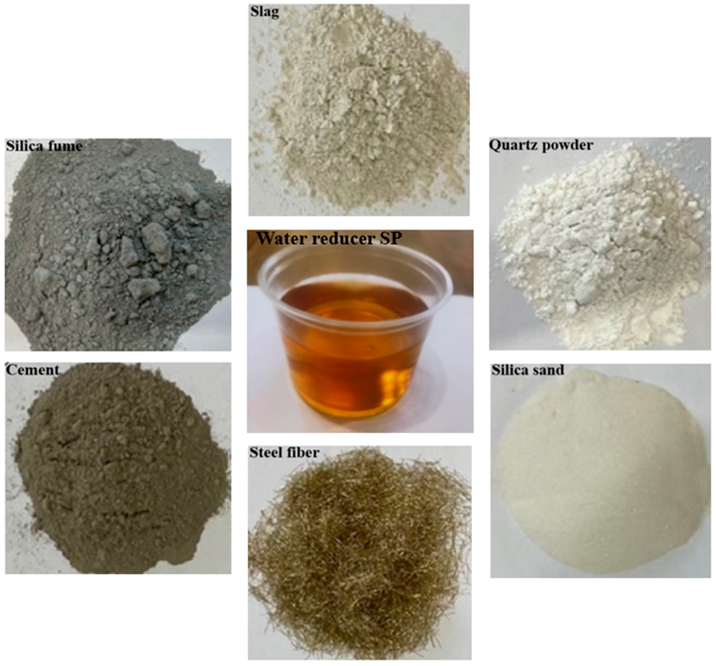
2.1. Materials

2.1.1. UHPC Materials
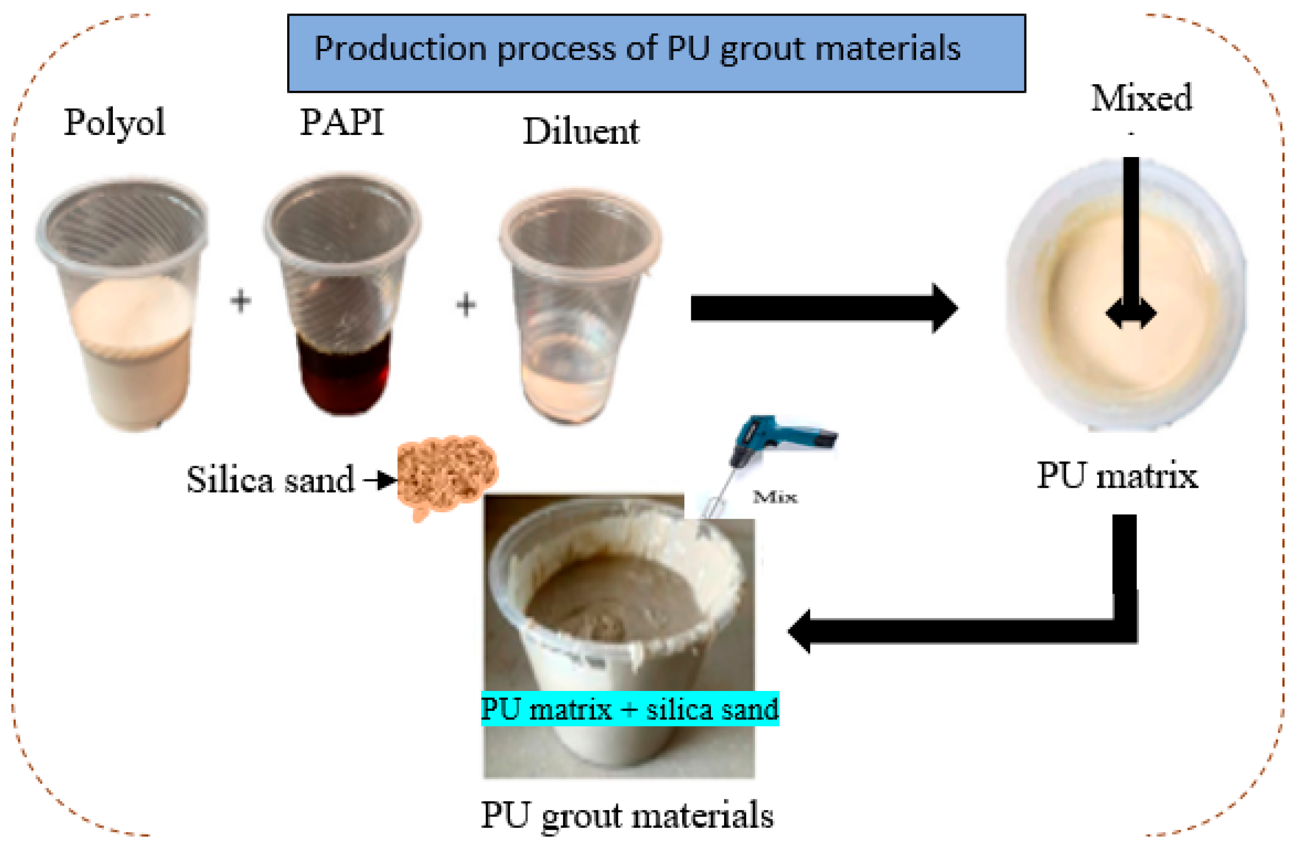
The UHPFRC mixture was prepared using Grade 52.5R cement. Silica fume, with a particle size of 0.1–0.2 μm and a specific surface area of 18,500 m2/kg, was included in the mix. Additionally, S95-grade slag powder was utilized, conforming to the national standard GB/T18046-2000 [35]. The silica sand employed had a particle size between 120 and 200 mesh, while quartz powder served as a filler. A polycarboxylate-based superplasticizer was added to maintain workability. The mixture was reinforced with 13 mm long and 0.2 mm diameter micro-steel fibers. Figure 1 illustrates the key materials involved in formulating the UHPFRC mixtures.

2.1.2. PUG Material

The two-component PU consisted of substances A and B. Substance A is a bio-based PU derived from castor oil, and substance B is a polydactyl polymethylene isocyanate (PAPI) with a viscosity of 250 Poise at 25 °C. PAPI and castor oil were combined in a 6:1 weight ratio to synthesize the PU matrix and mixed in a cup. The mixing process involved using a mechanical stirrer at 600 rpm for about 2 min at room temperature. Silica sand PU binder was combined using a 1:1 weight ratio to form PU grout and strengthen the U-shaped UHPC specimen.

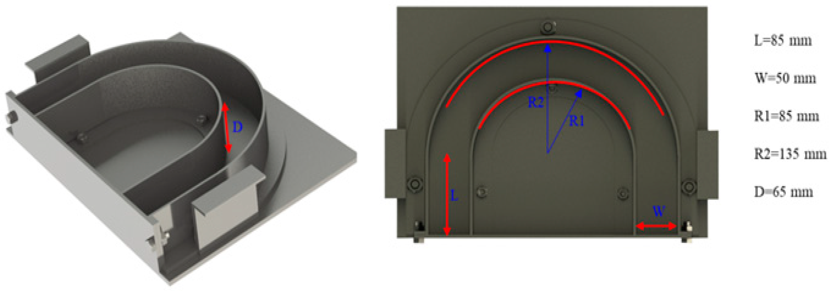
2.2. Specimen Preparation

The UHPC was developed by incorporating 25% silica fume into a binder-to-water ratio of 0.16. To achieve optimal workability, ranging from 195 to 210 mm, 20% of a water-reducing agent by weight of the binder was included in the mix design. The design mix of the UHPFRC components is detailed in Table 1. The mixing process began with a dry mixing of constituent materials under low speed in a 60 L concrete mixer for two to three minutes. Water and superplasticizer were added, and mixing continued for 10 min. The speed was set to high for one minute, resulting in a uniform UHPFRC mixture. Following a precise mixing and proportioning protocol, the mixture attained the required fresh and hardened properties. The mixture was then cast into U-shaped molds, with the geometry of the U-shape detailed in Figure 2.

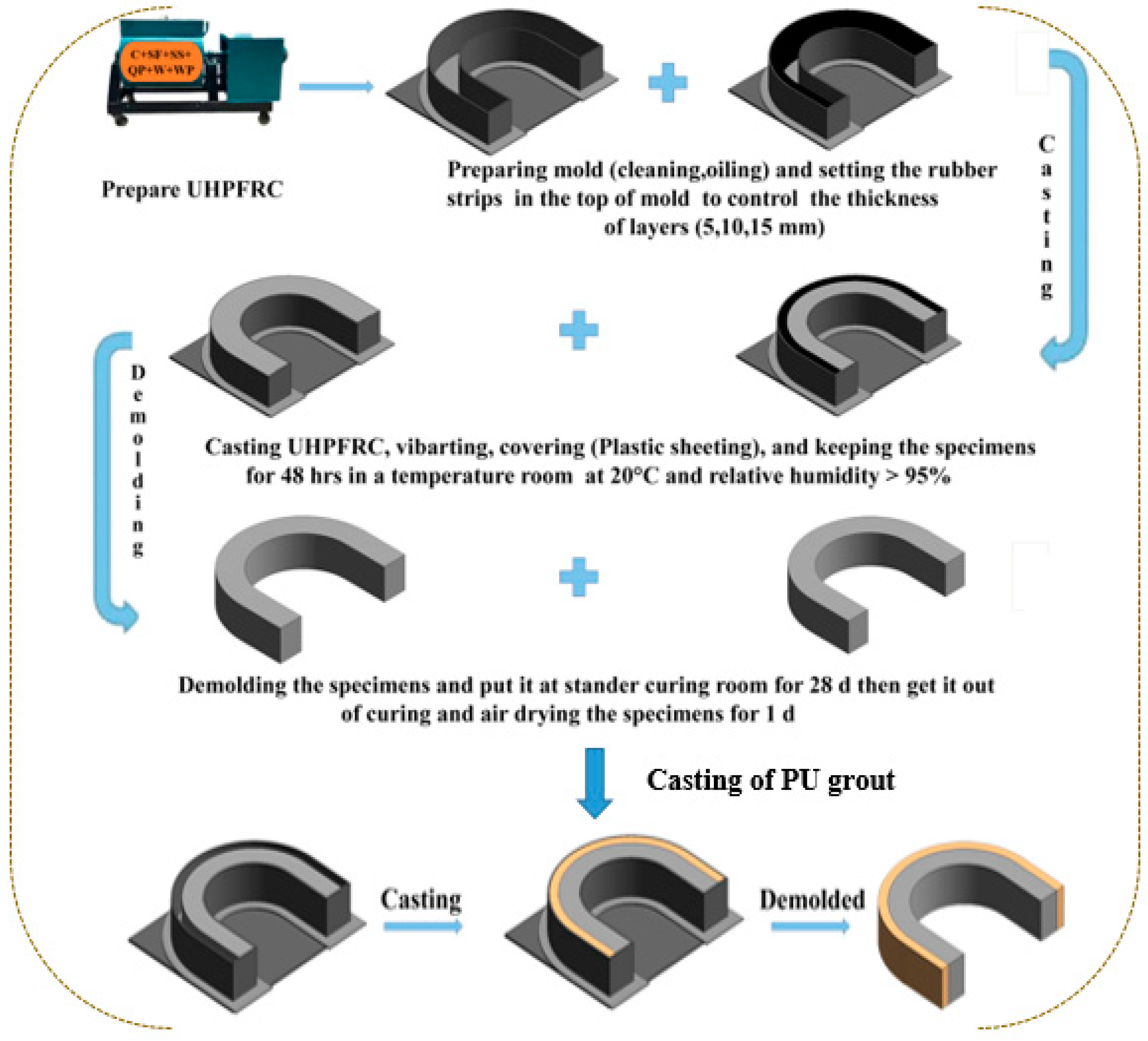
2.3. Fabrication of Samples

The fresh UHPFRC was cast in U-shaped and cube molds for impact and compression tests. The specimens were kept at room temperature for about 48 h before being de-molded and then cured in a standard curing room for 28 days. After curing, the U-shaped UHPC specimens from each group (12 specimens per group) were completely dried before casting the PU grout overlay. The grouting material was mixed in a cup using a mechanical mixer at 600 rpm until a uniform consistency was achieved. Table 2 details the formulation of the PU grout, and Figure 3 illustrates the process for creating the PU grout overlay. After curing, the UHPC specimens were removed from the curing room and allowed to air dry for five days to eliminate any remaining moisture, with no additional surface treatment performed before casting the PU grout. The U-shaped sample was then strengthened with a PUG layer with a depth of 5, 10, and 15 mm, as shown in Figure 4.

2.4. Testing Method

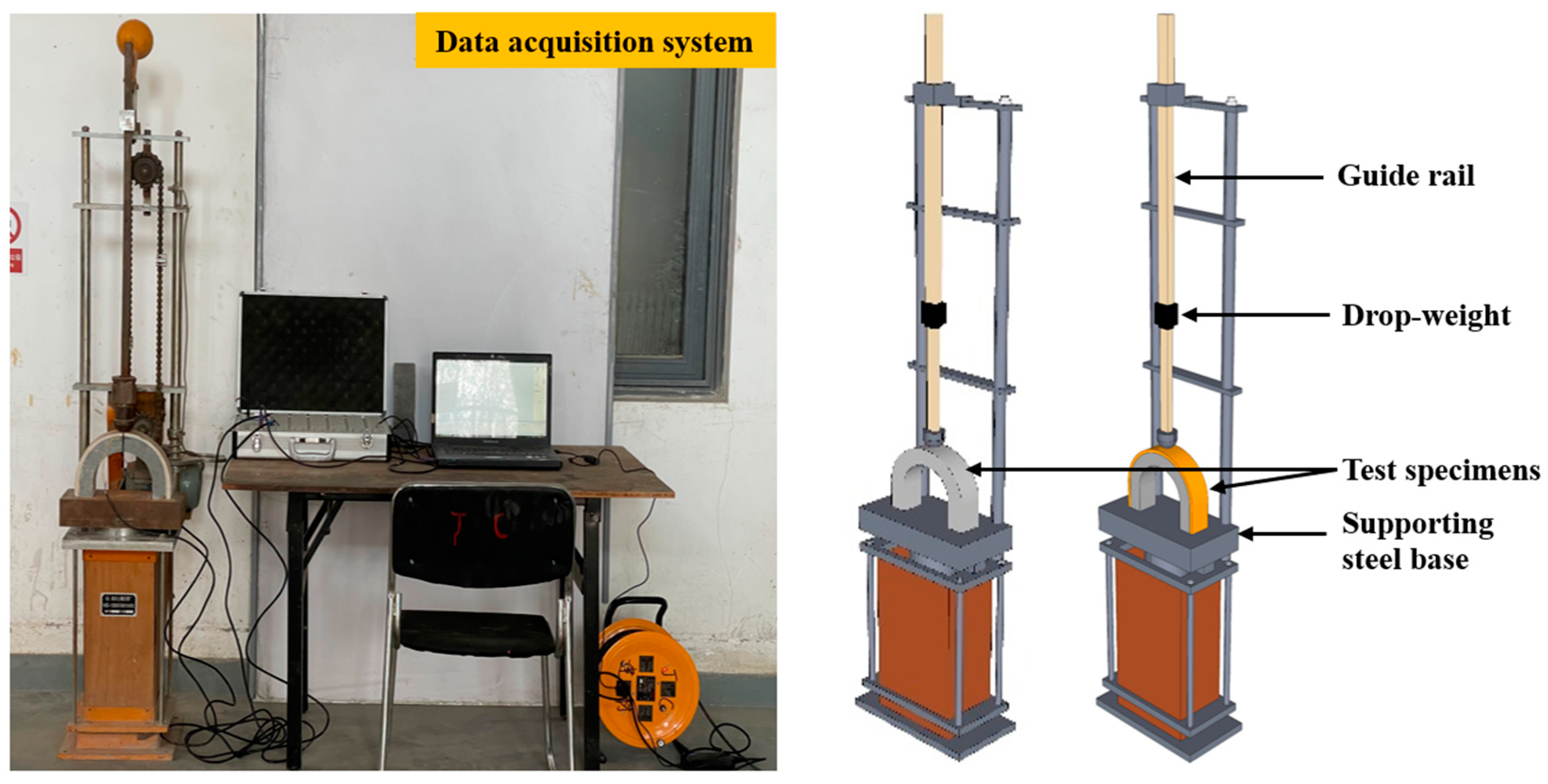
2.4.1. Drop-Weight Impact Test

The test setup of DWI for evaluating U-shaped UHPFRC’s impact strength is depicted in Figure 5. This testing method was adapted from the ACI 544 standards [31] due to its simplicity and widespread acceptance for assessing the impact performance of concrete. The testing approach was adapted from past studies [36,37,38,39]. The number of blows required to reach the first crack point (N1) and achieve failure (N2) measures the specimen’s resistance to crack initiation and failure under impact. The drop-weight was released at 2 s intervals to simulate the impact conditions. The energy absorbed at the two cracking stages (initial and failure) was calculated based on the number of blows, mass, height, and gravitational acceleration used to determine velocity Equations (1) and (2).
I E i = N 1 · w g h = N 1 w v 2 2
I E f = N 2 · w g h = N 2 w v 2 2
where g denotes the acceleration due to gravity (9.81 m/s2), v represent the velocity of the falling weight, h is the height from which the hammer is dropped (450 mm), w is the weight of the hammer, N1 is the number of drops until the first crack appears, and N2 the drops number until the complete failure of the specimen.

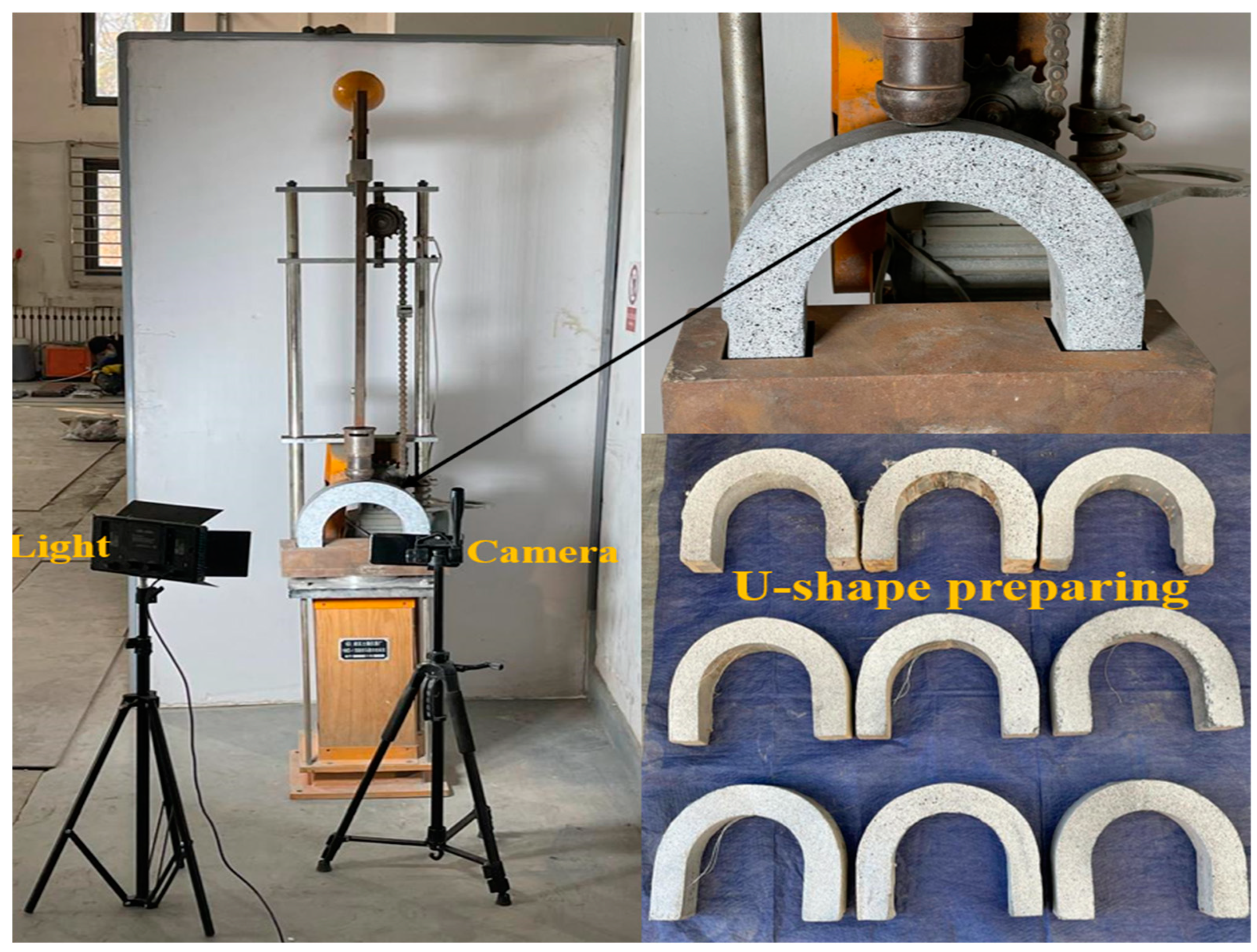
2.4.2. Digital Image Correlation Test

The dynamic DIC phase focused on capturing the failure behavior of U-shaped samples during DWI tests. Figure 6 illustrates the setup for the drop-weight impact test on U-shaped specimens and the DIC equipment. The DIC system comprised a high-resolution camera, a lighting setup, and a computer, all arranged in front of the specimen to monitor failure modes under repeated impact loading. To enable DIC analysis, a white and black speckled pattern was sprayed onto the front surface of the test sample. This speckled pattern consisted of randomly applied black and white dots or patches with particle sizes between 1 and 1.5 mm. The camera used was a 48-megapixel model with a 24 mm, 1.78-aperture, seven-element lens, providing an image resolution of 8064 × 6048 pixels. Consistent lighting was maintained during the test using a white LED spotlight mounted on a tripod next to the camera. The camera was positioned to focus on the front-facing area of the specimen. Image observation and analysis were conducted on a high-performance computer with a 16 GB Quadro graphics card, a 4.2 GHz Intel processor, and a 64-bit operating system.

3. Results and Discussions

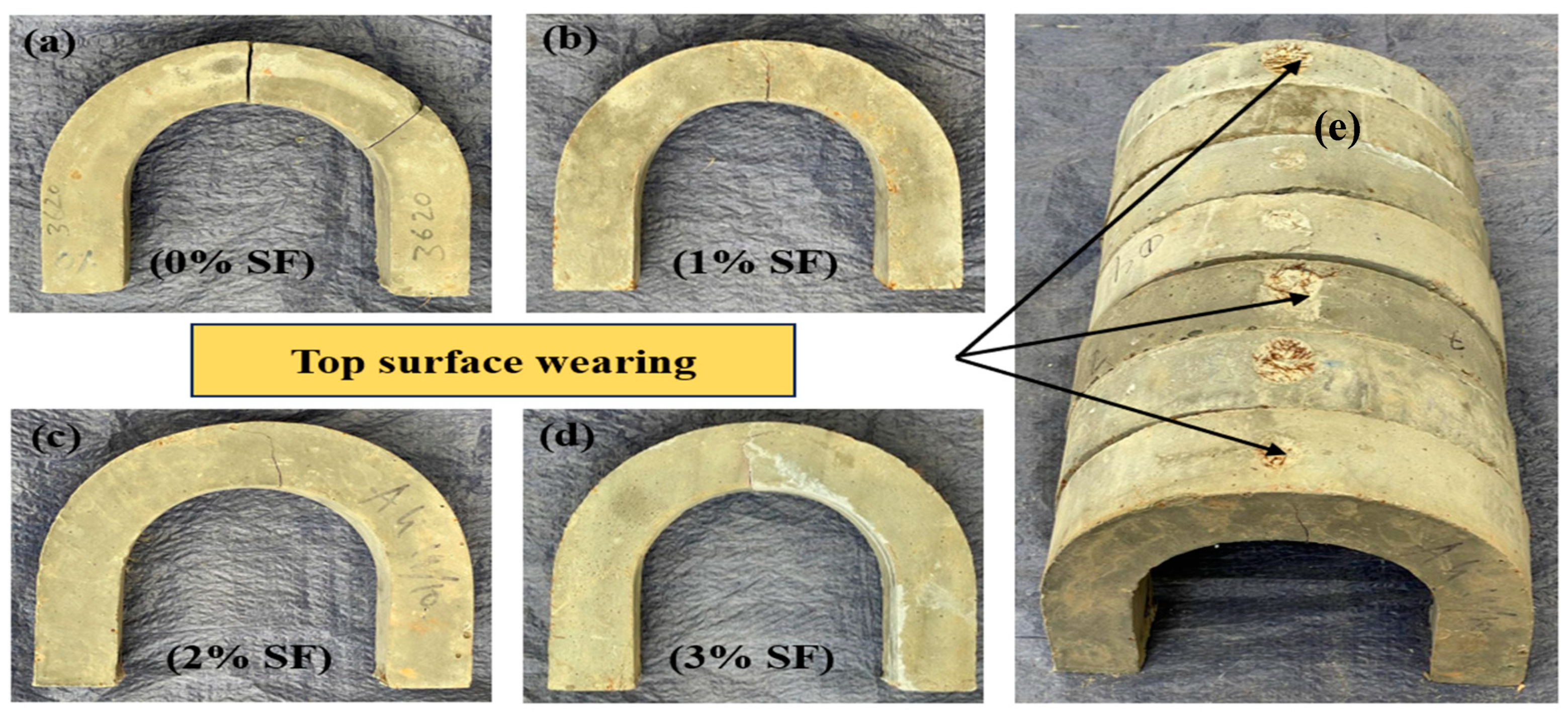
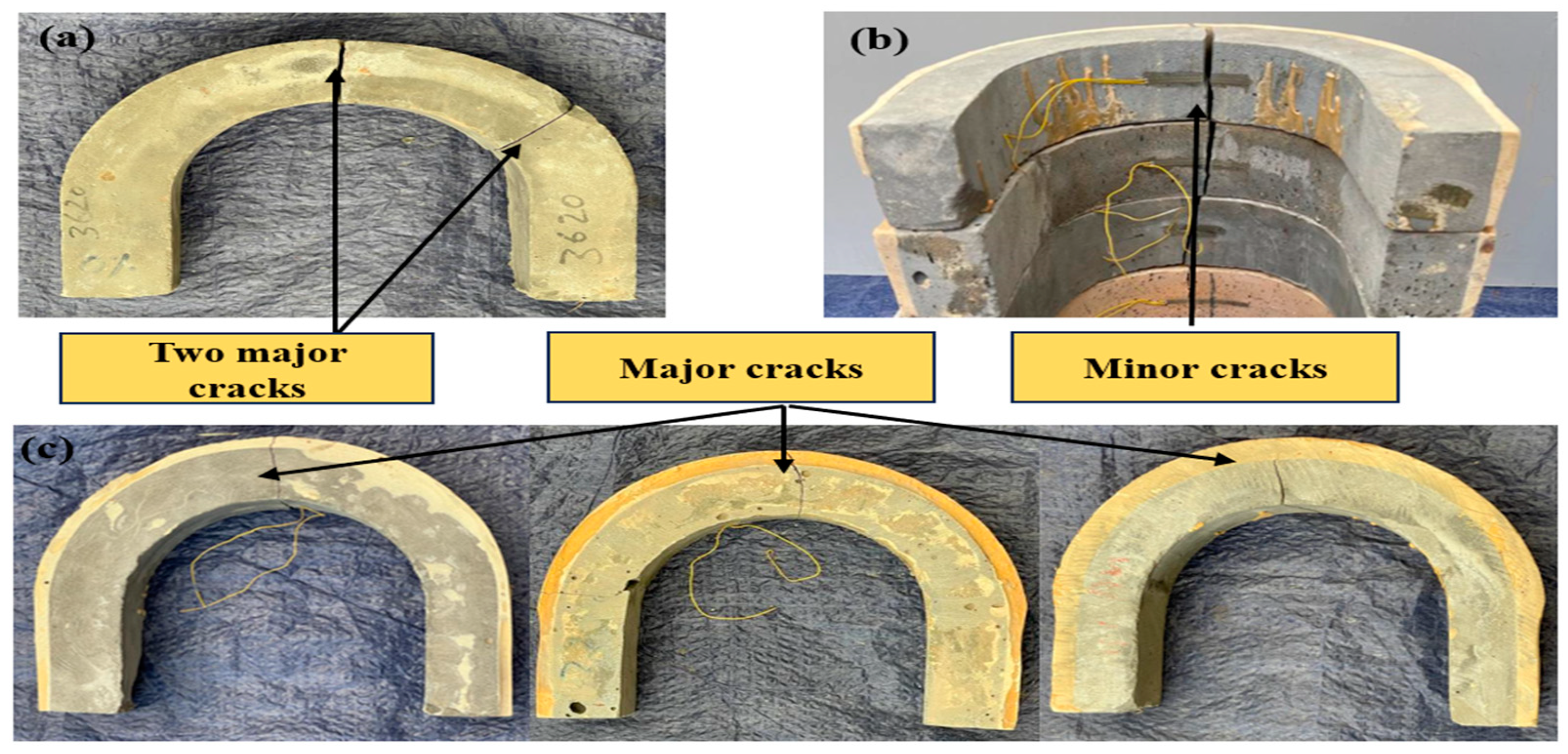
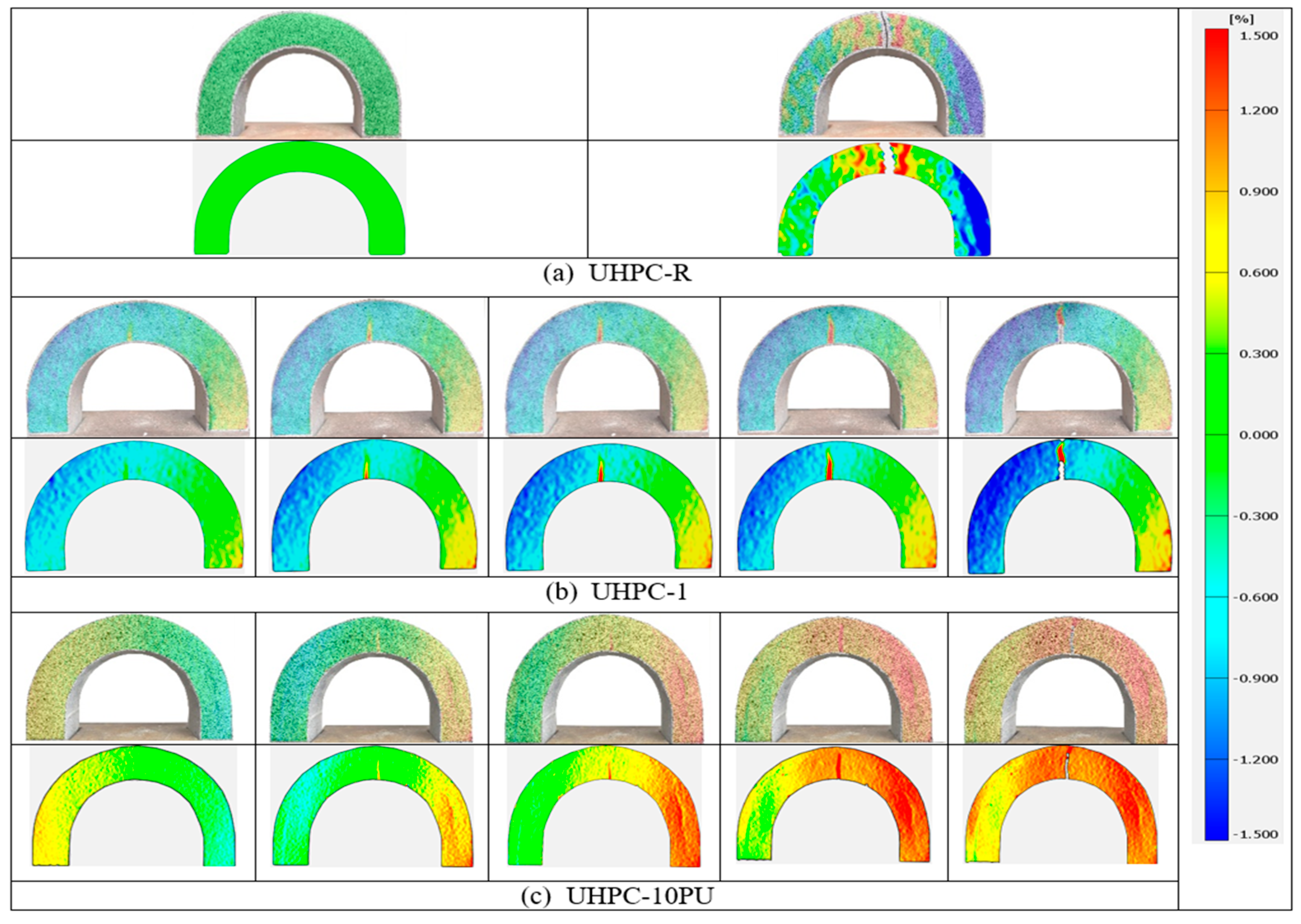
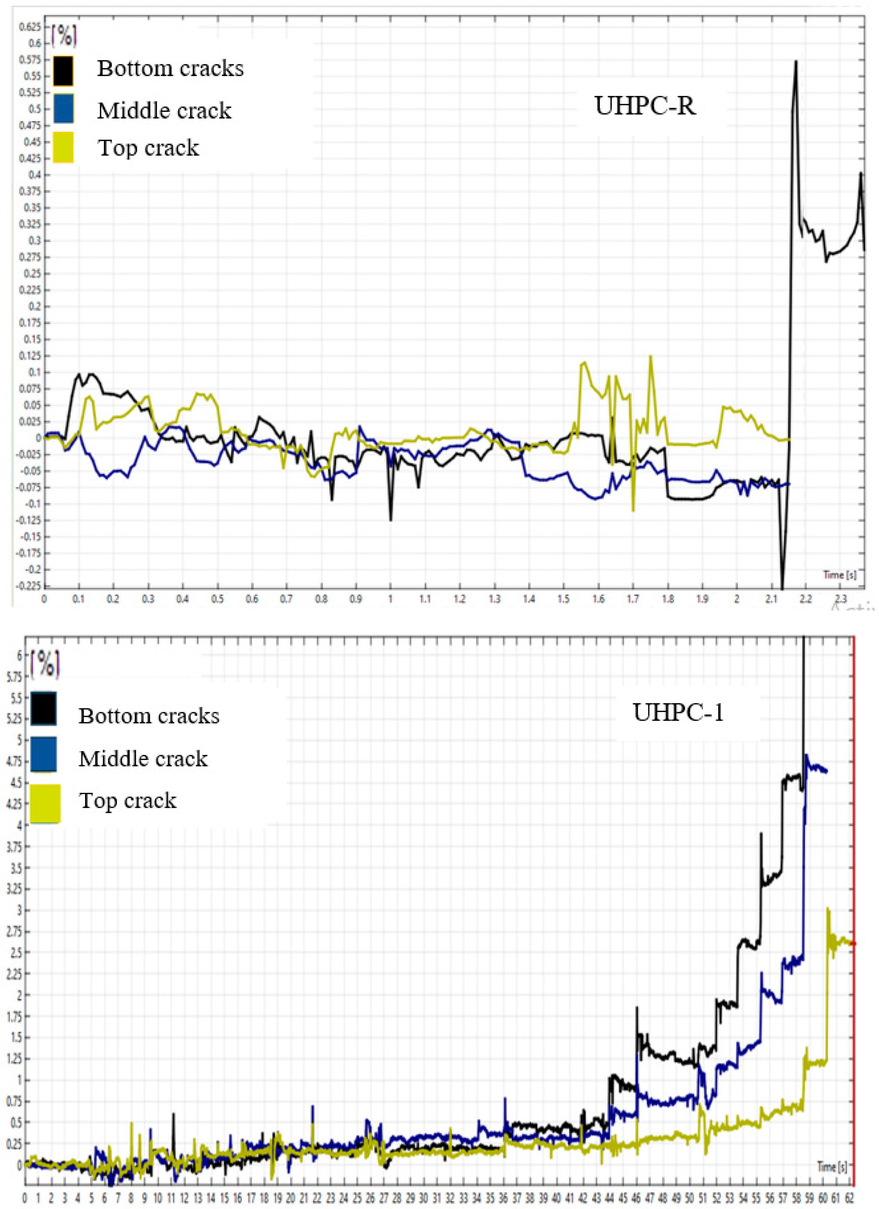
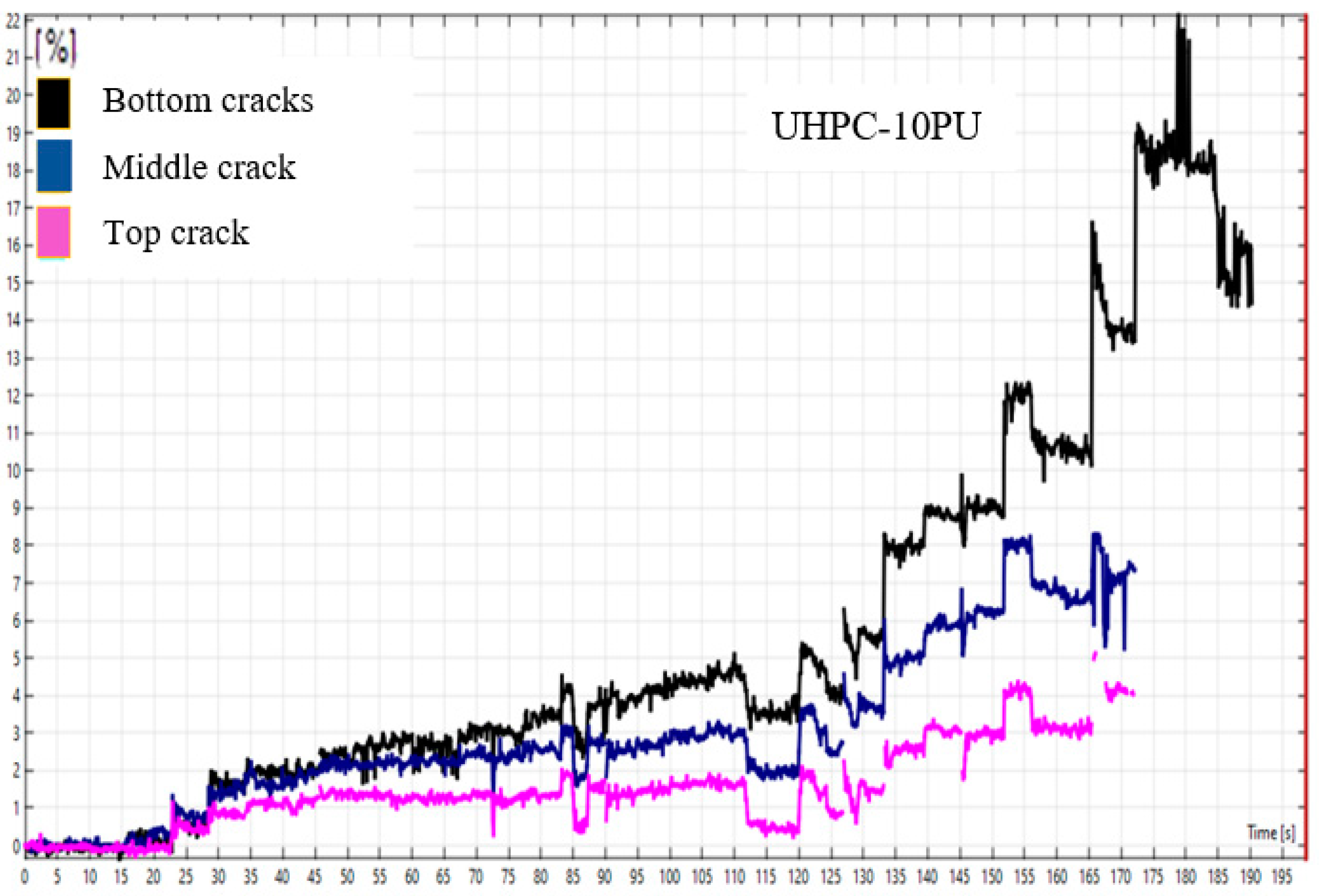
3.1. Failure Mode of U-Shaped UHPC

The failure pattern of U-shaped UHPC specimens is significantly influenced by the volume content of micro-steel fibers and the retrofit layer of PU grout material on the top surface of UHPC. For the control specimen without fibers or retrofit (Figure 7a and Figure 8c), a single major crack separates the specimen perpendicularly into two or three parts under drop-weight impact, indicating complete failure with a single drop due to the inherent brittleness of UHPC. In contrast, adding 1% steel fibers (UHPC-1, Figure 7b) causes crack deviation from the mid-section and a minor web crack compared to the control. A minor top web crack propagates to the mid-section at 2% fiber volume (Figure 7c), breaking the specimen into two parts. Increasing further to 3% fibers (UHPC-3, Figure 7d) allows the steel microfibers to overcome UHPC’s brittleness by enhancing ductility, resulting in minor middle web cracks propagating to the bottom. At the same time, the top surface disintegrates under repeated loads. When retrofitted with a PU grout overlay (Figure 8), the U-shaped specimens exhibit a single minor bottom-to-top crack in the mid-section, minimizing crack propagation compared to cylinder specimens per ACI 544 recommendations. The primary failure mode breaks the retrofit specimens into two parts without crushing or spalling, similar to previous studies. Importantly, no interfacial failure occurs between UHPC and overlay under impact loads. However, some control specimens without retrofit still crack in two critical areas at higher load intensity, separating into three pieces (Figure 8a) due to the intrinsic brittleness. The U-shape geometry concentrates stress at three key areas—the mid-section and two opposite bend sections—initiating another major outer-to-inner crack in the bend region.
Figure 9 and Figure 10 illustrate a detailed examination of the failure progression in UHPC specimens under dynamic loading via DWI tests. Figure 9 represents strain in the UHPC specimens under dynamic loading, where positive values (0% to 1.5%) indicate tensile strain (stretching), and negative values (0% to −1.5%) indicate compressive strain (compression). This helps visualize strain distribution and failure patterns in different UHPC types. Figure 9 offers a comprehensive visualization of the strain distribution over time. Figure 10 presents the corresponding strain–time curves for various specimen types, illustrating the differences in failure response among UHPC-R, UHPC-1, and UHPC-10PU. For the unmodified reference UHPC (UHPC-R), failure occurs rapidly, typically within the first or second impact, as shown in the sharp spike in the strain–time curve. The digital image correlation (DIC) technique captures this quick failure, with the strain localized and maximized at the impact points, indicating the brittleness and limited energy absorption capacity of the standard UHPC mix. In contrast, the UHPC-1 specimens, which include a 1% volume fraction of micro-steel fiber, show a more gradual increase in strain over larger impacts before initial propagation occurs. This suggests that the fiber reinforcement within the UHPC matrix improves the material’s toughness and resistance to crack initiation. The strain is more distributed throughout the U-shaped specimen, delaying the onset of a critical crack and allowing the specimen to absorb more energy.
The cracking behavior of the UHPC specimens under dynamic loading conditions complements the strain distribution data presented earlier (see Figure 10). The curves show the progression of cracks at different locations (bottom, middle, and top) of the specimens over time. For the UHPC-R specimen, the rapid rise in crack measurements, especially at the bottom, aligns with the strain localization. This behavior confirms a brittle failure mechanism where the specimen exhibits minimal resistance to dynamic loading, resulting in quick crack propagation. The sudden spike in crack levels indicates that once cracking initiates, it rapidly progresses due to the lack of reinforcing elements to distribute the stress. The cracking behavior under dynamic loads for different UHPC specimens—UHPC-R (reference), UHPC-1 (with 1% micro-steel fiber), and UHPC-10PU (with a 10 mm polyurethane layer) is shown in Figure 10. The strain–time curves for each specimen show how cracks initiate and propagate in different locations (bottom, middle, and top cracks).
The UHPC-10PU specimens, featuring a 10 mm polyurethane grouting layer, exhibit a distinct failure pattern, with the strain–time curves demonstrating an extended resistance to initial cracking and a higher threshold before catastrophic failure. This enhanced performance is attributable to the PU layer’s ability to dissipate energy and introduce a degree of flexibility and damping into the system, which is not present in the fiber-reinforced or reference specimens. The DIC technique, utilized in both figures, provides a high-fidelity view of the deformation and strain localization, which occurs primarily at the mid-section of the U-shaped specimens, which agrees with previous studies. This region experiences the highest stress concentration due to the dynamic loading conditions, making it the most likely site for initiating and propagating cracks. By comparing the failure progression across the three specimen types, it is evident that the addition of micro-steel fibers and the inclusion of a PU grouting layer each contribute uniquely to enhancing the dynamic impact resistance of UHPC. The fibers increase the energy required to initiate a crack. At the same time, the PU layer provides a significant boost to the energy needed for final failure, showcasing the potential for these modifications to tailor UHPC performance for applications where resistance to dynamic loading is critical.

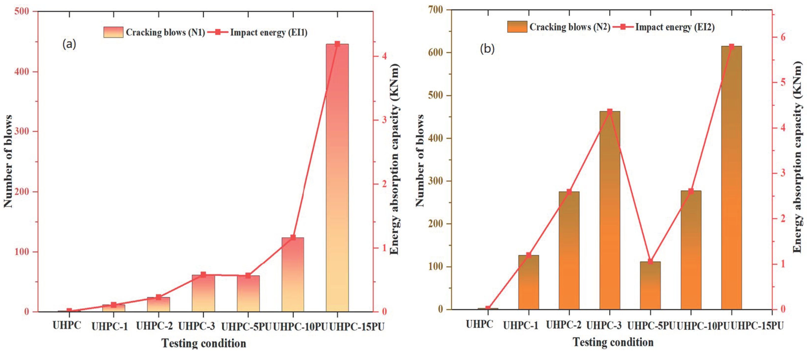
3.2. Impact Strength of UHPC

The impact resistance of UHPC under repetitive drop-weight impact loads was significantly improved by incorporating micro-steel fibers and applying polyurethane (PU) grout overlays, as shown in Table 3 and Figure 11a,b. Additionally, the energy absorption capacity (El) during the initial crack and failure stage was enhanced, increasing with the volume of steel fibers and the thickness of the PU grouting layer. The control UHPC-R specimens without reinforcement or overlay exhibited meager impact resistance, failing with a single blow. Introducing a 1% volume fraction of micro-steel fibers (UHPC-1) led to a remarkable improvement, with an average of 12 blows required for the first crack and 127 blows for failure, demonstrating the reinforcing effect of the fibers. Further increasing the fiber content to 2% (UHPC-2) resulted in a 100% increase in the first crack impact strength (24 blows) and a 117% increase in the failure impact strength (275 blows) compared to UHPC-1. The impact resistance was further amplified with 3% fiber volume fraction (UHPC-3), exhibiting a 408% higher first crack impact strength (49 blows) and a staggering 264.56% higher failure impact strength (336 blows) than UHPC-1 and 68.36% higher failure impact strength than UHPC-2. These substantial improvements highlight the effectiveness of micro-steel fibers in enhancing the impact properties of UHPC. Complementing the fiber reinforcement, applying PU grout overlays also yielded remarkable enhancements in impact resistance. While the control UHPC-R specimens failed with just a single blow, the UHPC specimens with a 5 mm PU grout overlay (UHPC-5PU) exhibited an increase in first crack impact strength from 60 blows and 112 blows for failure impact strength compared to the control. Increasing the overlay thickness further amplified the impact resistance, with UHPC-10PU achieving 107% and 147% higher first crack and failure impact strengths, respectively, compared to UHPC-5PU, and UHPC-15PU exhibiting a remarkable 363% and 449% higher first crack and failure impact strengths than UHPC-5PU. These findings underscore the synergistic effect of micro-steel fiber reinforcement and PU grout overlays in significantly enhancing the impact resistance and ductility of UHPC, making it a promising material for military and civil structures subjected to severe impact loads.

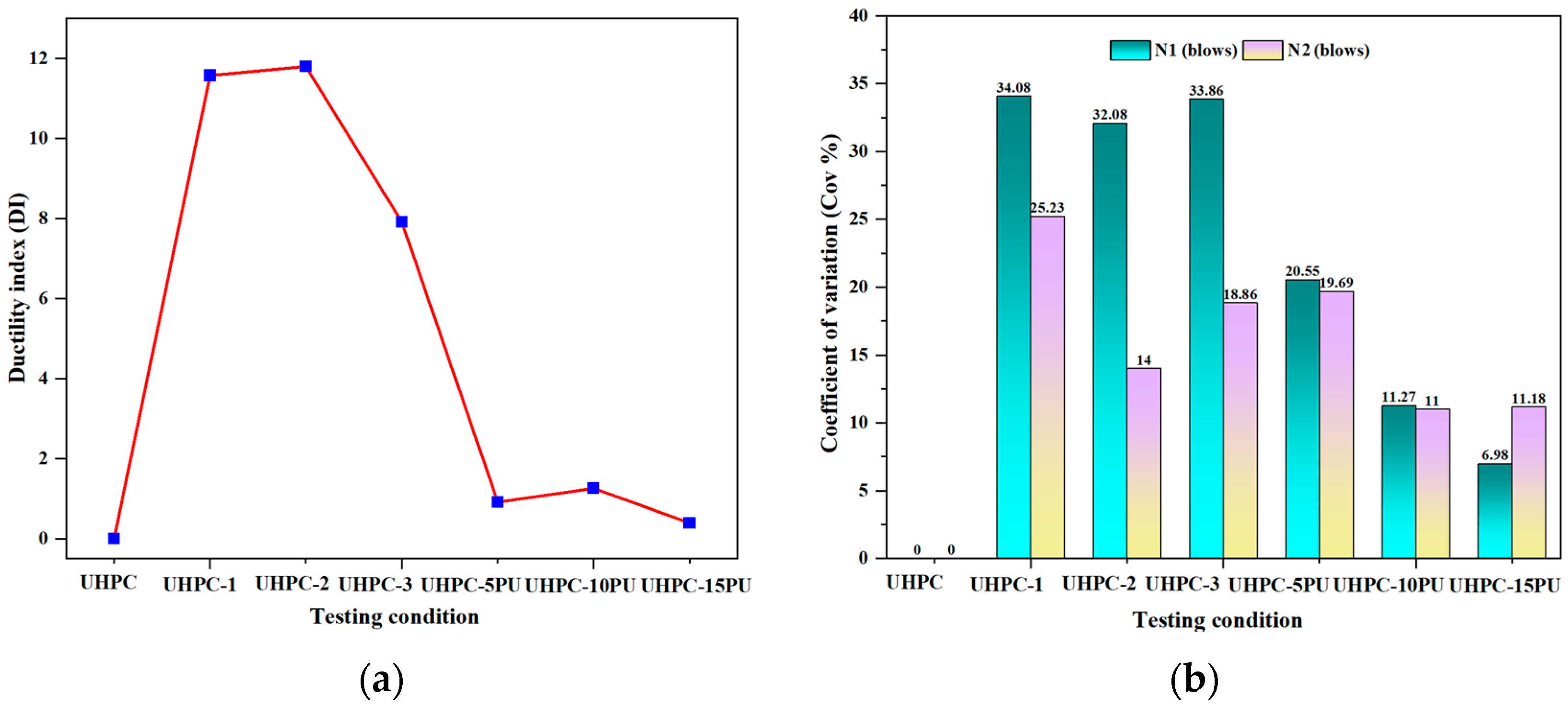
3.3. Ductility Index and Coefficient of Variation

The incorporation of fiber into cementitious composite and polyurethane (PU) grouting layers serves to alter their properties from brittle to ductile when subjected to impact stress. The ductility index (DI) quantifies the tenacity of these materials. Post-cracking behavior of UHPC is quantified as the ratio of impact blows to failure fracture (N2) from the initial crack (N1) during the two cracking phases [40,41].
D u c t i l i t y   i n d e x   ( D I ) = ( N 2 N 1 ) N 1
The ability of the test specimens to absorb kinetic energy is assessed by average DI values. Figure 12a illustrates the average DI-value for each UHPC group, which is utilized to characterize the kinetic energy absorption capability of U-shaped UHPC specimens [42]. The impact load caused a transformation in the properties of UHPC from brittle to ductile due to the micro-steel fiber. Due to the enhanced post-crack blows (N2) caused by the addition of steel fiber, the U-shaped UHPC exhibited a high degree of ductility, indicative of the mixture’s toughness as U-shaped UHPC. In contrast, the ductility index decreased due to the large steel fiber volume fraction. The average DI value rises and falls as the fiber volume fraction increases. UHPC-1 demonstrates a DI-value of 11.57, while UHPC-2 showed a slight increase. The DI-value was reduced to 7.91 for UHPC-3 specimens. A higher DI value is not expected for UHPC matrices with a high fiber volume fraction, as depicted in Figure 12a. High fiber content delays the formation of cracks at two stages, enhancing the impact behavior. Nonetheless, certain past studies have indicated a DI-value of 1.5 [43]. The reduction in DI value was attributed to the significant number of drops attained before the start of N1, which is responsible for elucidating the DI, as indicated in Equation 9. Furthermore, Figure 11 shows that UHPC-3 had higher N1 values than UHPC-1 and UHPC-2. This finding corroborated the findings seen in the literature [41,44]. In contrast, UHPC specimens with PU grouting layers displayed a different pattern of ductility improvement. The 5 mm PU layer reinforced UHPC-5PU and UHPC-10 exhibited a DI of 0.91 and 1.258, respectively, indicating an increase in toughness compared to reference specimen (UHPC-R), which is zero ductility. Remarkably, the UHPC-15PU, with the thickest PU grouting layer examined, displays a decrease in DI to 0.39, which might suggest a reduction in ductility, as mentioned above. The PU layer delays crack progress at two stages, improving impact strength. Also, adding fiber showed a higher DI value index than the PU layers. However, the PU layers showed more absorbing, dispersing, and delaying of the first and failure cracks than UHPC with microfibers (Table 3), which means it increases the ductility of UHPC more than adding microfiber. The UHPC specimens with 5mm PU grouting layers demonstrate even more significant impact resistance of UHPC-R and UHPC-1 by 5900% and 400%, respectively, for N1, which increases the N1 from 1 and 12 to 60 blows, and from 1 and 127 blows for N2 to 275; the same thing is observed with UHPC-10PU and UHPC-15 when compared with UHPC-2 and UHPC-3, increasing by 416% and 631% for N1 and 1% and 33% for N2. Figure 12b displays the coefficient of variation (CoV) of the number of drops at the two cracking stages. The investigation recorded 34.08% and 11.18% CoV values for the UHPC-1 and UHPC-15PU samples at first crack and failure, respectively. The significant difference occurs because the initial break must be detected through visual monitoring, as cracks might develop in various locations [45].

4. Conclusions

The influence of steel fiber and retrofitting on UHPC were compared to enhance the impact strength of UHPC. The SF was introduced into the UHPC mixes from 0 to 3% Vf (in 1% increments), and PU grouting overlays of varying thicknesses—5 mm, 10 mm, and 15 mm—were applied. The digital image correlation (DIC) method was implemented to process the experimental data for the failure crack N2 stage. In summary, the following conclusions were derived from the findings:
  • The U-shaped specimen facilitated the regulation of crack development. Reference UHPC experienced complete failure with a single drop, resulting in the test specimen being divided into two sections. In contrast, the UHPC containing fiber exhibited other web cracks alongside significant cracks.
  • The brittleness of UHPC has been mitigated by adding SF and retrofitting techniques. The ability of U-shaped UHPC mixtures to withstand impact loads is enhanced with an increase in fiber volume fraction or PU grouting thickness.
  • A thicker polyurethane (PU) overlay substantially improved the impact behavior of UHPC specimens by delaying cracking and enhancing failure loads. UHPC-10PU exhibited 107% and 147% higher first crack and failure impact strengths than UHPC-5PU, respectively. Remarkably, UHPC-15PU showed 363% and 449% higher first crack and failure strengths than UHPC5PU. Moreover, UHPC-5PU and UHPC-15PU demonstrated 400% and 33% superior impact performance over UHPC-1 and UHPC-3 at the first crack and failure stages, respectively.
  • Adopting a U-shaped specimen geometry-controlled crack propagation to predetermined locations reduces variability in impact resistance data compared to the standard ACI 544 testing procedure. The coefficient of variation in this study ranged from 11.93% to 31%, lower than typical variations observed with the ACI 544 method.

Author Contributions

H.Z. and Y.E.I.: conceptualization, investigation, supervision, resources, project administration, and funding acquisition; A.A.-s. and S.I.H.: conceptualization, methodology, investigation, data curation, writing—original draft, writing—review and editing, visualization, and formal analysis; S.A.L.: data curation, writing—original draft, and writing—review and editing. All authors have read and agreed to the published version of the manuscript.

Funding

This research was funded by the Natural Science Foundation of China (No. 51708314), and the APC was funded by the Structures and Materials Laboratory (S&M Lab) of the College of Engineering, Prince Sultan University, Riyadh, Saudi Arabia.

Data Availability Statement

Data are contained within the article.

Acknowledgments

The authors express their deep gratitude for the financial support provided by the Natural Science Foundation of China (Grant No. 51708314). Additionally, they appreciate the Structures and Materials Laboratory (S&M Lab) at the College of Engineering, Prince Sultan University, Riyadh, Saudi Arabia, for covering the article processing fees.

Conflicts of Interest

The authors declare no conflicts of interest.

References

  1. Wang, W.; Chouw, N. The behaviour of coconut fibre reinforced concrete (CFRC) under impact loading. Constr. Build. Mater. 2017, 134, 452–461. [Google Scholar] [CrossRef]
  2. Nili, M.; Afroughsabet, V. Combined effect of silica fume and steel fibers on the impact resistance and mechanical properties of concrete. Int. J. Impact Eng. 2010, 37, 879–886. [Google Scholar] [CrossRef]
  3. Murali, G.; Ramprasad, K. A feasibility of enhancing the impact strength of novel layered two stage fibrous concrete slabs. Eng. Struct. 2018, 175, 41–49. [Google Scholar] [CrossRef]
  4. Zhang, W.; Chen, S.; Zhang, N.; Zhou, Y. Low-velocity flexural impact response of steel fiber reinforced concrete subjected to freeze-thaw cycles in NaCl solution. Constr. Build. Mater. 2015, 101, 522–526. [Google Scholar] [CrossRef]
  5. Abid, S.R.; Shamkhi, M.S.; Mahdi, N.S.; Daek, Y.H. Hydro-abrasive resistance of engineered cementitious composites with PP and PVA fibers. Constr. Build. Mater. 2018, 187, 168–177. [Google Scholar] [CrossRef]
  6. Abid, S.R.; Hilo, A.N.; Daek, Y.H. Experimental tests on the underwater abrasion of Engineered Cementitious Composites. Constr. Build. Mater. 2018, 171, 779–792. [Google Scholar] [CrossRef]
  7. Wu, C.; Li, J.; Su, Y.D. Development of Ultra-High Performance Concrete against Blasts: From Materials to Structures; Woodhead Publishing: Sawston, UK, 2018. [Google Scholar]
  8. Su, Y.; Li, J.; Wu, C.; Wu, P.; Li, Z.-X. Effects of steel fibres on dynamic strength of UHPC. Constr. Build. Mater. 2016, 114, 708–718. [Google Scholar] [CrossRef]
  9. Chun, B.; Yoo, D.-Y. Hybrid effect of macro and micro steel fibers on the pullout and tensile behaviors of ultra-high-performance concrete. Compos. Part B Eng. 2019, 162, 344–360. [Google Scholar] [CrossRef]
  10. Zhang, B.; Feng, Y.; Xie, J.; He, J.; Yu, T.; Cai, C.; Huang, D. Compressive behaviours, splitting properties, and workability of lightweight cement concrete: The role of fibres. Constr. Build. Mater. 2022, 320, 126237. [Google Scholar] [CrossRef]
  11. Wang, J.; Xie, J.; Wang, Y.; Liu, Y.; Ding, Y. Rheological properties, compressive strength, hydration products and microstructure of seawater-mixed cement pastes. Cem. Concr. Compos. 2020, 114, 103770. [Google Scholar] [CrossRef]
  12. Abadi, P.M.S.; Baluch, A.H.; Sebaey, T.A.; Peeters, D.; Barzegar, M.; Lopes, C.S. Dispersed-ply design and optimization to improve the brittle flexural behaviour of composite laminates. Compos. Part A Appl. Sci. Manuf. 2023, 164, 107277. [Google Scholar] [CrossRef]
  13. Huang, L.; Su, L.; Xie, J.; Lu, Z.; Li, P.; Hu, R.; Yang, S. Dynamic splitting behaviour of ultra-high-performance concrete confined with carbon-fibre-reinforced polymer. Compos. Struct. 2022, 284, 115155. [Google Scholar] [CrossRef]
  14. Fan, D.; Yu, R.; Shui, Z.; Liu, K.; Feng, Y.; Wang, S.; Li, K.; Tan, J.; He, Y. A new development of eco-friendly Ultra-High performance concrete (UHPC): Towards efficient steel slag application and multi-objective optimization. Constr. Build. Mater. 2021, 306, 124913. [Google Scholar] [CrossRef]
  15. Bragov, A.M.; Petrov, Y.V.; Karihaloo, B.L.; Konstantinov, A.Y.; Lamzin, D.A.; Lomunov, A.K.; Smirnov, I.V. Dynamic strengths and toughness of an ultra high performance fibre reinforced concrete. Eng. Fract. Mech. 2013, 110, 477–488. [Google Scholar] [CrossRef]
  16. Su, Y.; Li, J.; Wu, C.; Wu, P.; Tao, M.; Li, X. Mesoscale study of steel fibre-reinforced ultra-high performance concrete under static and dynamic loads. Mater. Des. 2017, 116, 340–351. [Google Scholar] [CrossRef]
  17. Khosravani, M.R.; Silani, M.; Weinberg, K. Fracture studies of ultra-high performance concrete using dynamic Brazilian tests. Theor. Appl. Fract. Mech. 2018, 93, 302–310. [Google Scholar] [CrossRef]
  18. Pedram, Z.; Amir, M. Cyclic Behavior of Hybrid Columns Made of Ultra High Performance Concrete and Fiber Reinforced Polymers. J. Compos. Constr. 2012, 16, 91–99. [Google Scholar]
  19. Guo, Y.; Xie, J.; Xie, Z.; Zhong, J. Experimental study on compressive behavior of damaged normal-and high-strength concrete confined with CFRP laminates. Constr. Build. Mater. 2016, 107, 411–425. [Google Scholar] [CrossRef]
  20. Huang, L.; Xie, J.; Li, L.; Xu, B.; Huang, P.; Lu, Z. Compressive behaviour and modelling of CFRP-confined ultra-high performance concrete under cyclic loads. Constr. Build. Mater. 2021, 310, 124949. [Google Scholar] [CrossRef]
  21. Barr, B.; Baghli, A. A repeated drop-weight impact testing apparatus for concrete. Mag. Concr. Res. 1988, 40, 167–176. [Google Scholar] [CrossRef]
  22. Kishi, N.; Konno, H.; Ikeda, K.; Matsuoka, K.G. Prototype impact tests on ultimate impact resistance of PC rock-sheds. Int. J. Impact Eng. 2002, 27, 969–985. [Google Scholar] [CrossRef]
  23. Yıldırım, G.; Khiavi, F.E.; Anıl, Ö.; Şahin, O.; Şahmaran, M.; Erdem, R.T. Performance of engineered cementitious composites under drop-weight impact: Effect of different mixture parameters. Struct. Concr. 2020, 21, 1051–1070. [Google Scholar] [CrossRef]
  24. Madjlessi, N.; Cotsovos, D.M.; Moatamedi, M. Drop-weight testing of slender reinforced concrete beams. Struct. Concr. 2021, 22, 2070–2088. [Google Scholar] [CrossRef]
  25. Cao, Y.Y.Y.; Liu, G.; Brouwers, H.J.H.; Yu, Q. Enhancing the low-velocity impact resistance of ultra-high performance concrete by an optimized layered-structure concept. Compos. Part B Eng. 2020, 200, 108221. [Google Scholar] [CrossRef]
  26. Wu, Z.; Shi, C.; He, W.; Wang, D. Static and dynamic compressive properties of ultra-high performance concrete (UHPC) with hybrid steel fiber reinforcements. Cem. Concr. Compos. 2017, 79, 148–157. [Google Scholar] [CrossRef]
  27. Kamaruddin, Z.H.; Jumaidin, R.; Kamaruddin, Z.H.; Asyraf, M.R.M.; Razman, M.R.; Khan, T. Effect of Cymbopogan citratus Fibre on Physical and Impact Properties of Thermoplastic Cassava Starch/Palm Wax Composites. Polymers 2023, 15, 2364. [Google Scholar] [CrossRef] [PubMed]
  28. Song, P.S.; Wu, J.C.; Hwang, S.; Sheu, B.C. Statistical analysis of impact strength and strength reliability of steel–polypropylene hybrid fiber-reinforced concrete. Constr. Build. Mater. 2005, 19, 1–9. [Google Scholar] [CrossRef]
  29. Qi, H.J.; Boyce, M.C. Stress–strain behavior of thermoplastic polyurethanes. Mech. Mater. 2005, 37, 817–839. [Google Scholar] [CrossRef]
  30. Badr, A.; Ashour, A.F.; Platten, A.K. Statistical variations in impact resistance of polypropylene fibre-reinforced concrete. Int. J. Impact Eng. 2006, 32, 1907–1920. [Google Scholar] [CrossRef]
  31. ACI 544.2R-89; Measurement of Properties of Fiber Reinforced Concrete. American Concrete Institute: Farmington Hills, MI, USA, 1989; pp. 433–439.
  32. Abid, S.R.; Hussein, M.L.A.; Ali, S.H.; Kazem, A.F. Suggested modified testing techniques to the ACI 544-R repeated drop-weight impact test. Constr. Build. Mater. 2020, 244, 118321. [Google Scholar] [CrossRef]
  33. Haruna, S.I.; Zhu, H.; Jiang, W.; Shao, J. Evaluation of impact resistance properties of polyurethane-based polymer concrete for the repair of runway subjected to repeated drop-weight impact test. Constr. Build. Mater. 2021, 309, 125152. [Google Scholar] [CrossRef]
  34. Zhu, X.C.; Zhu, H.; Li, H.R. Drop-weight impact test on U-shape concrete specimens with statistical and regression analyses. Materials 2015, 8, 5877–5890. [Google Scholar] [CrossRef] [PubMed]
  35. GB/T 18046-2000; Ground Granulated Blast Furnace Slag Used for Cement and Concrete. Standard Press of China: Beijing, China, 2000.
  36. Haruna, S.I.; Zhu, H.; Ibrahim, Y.E.; Shao, J.; Adamu, M.; Farouk, A.I.B. Experimental and Statistical Analysis of U-Shaped Polyurethane-Based Polymer Concrete under Static and Impact Loads as a Repair Material. Buildings 2022, 12, 1986. [Google Scholar] [CrossRef]
  37. Haruna, S.I.; Zhu, H.; Shao, J. Experimental study, modeling, and reliability analysis of impact resistance of micro steel fiber-reinforced concrete modified with nano silica. Struct. Concr. 2022, 23, 1659–1674. [Google Scholar] [CrossRef]
  38. Al-shawafi, A.; Zhu, H.; Haruna, S.I.; Bo, Z.; Laqsum, S.A.; Borito, S.M. Experimental study and machine learning algorithms for evaluating the performance of U-shaped ultra-high performance reinforced fiber concrete under static and impact loads. J. Build. Eng. 2023, 70, 106389. [Google Scholar] [CrossRef]
  39. Al-shawafi, A.; Zhu, H.; Haruna, S.I.; Bo, Z.; Laqsum, S.A.; Borito, S.M. Impact resistance of ultra-high-performance concrete retrofitted with polyurethane grout material: Experimental investigation and statistical analysis. Structures 2023, 55, 185–200. [Google Scholar] [CrossRef]
  40. Prasad, N.; Murali, G. Exploring the impact performance of functionally-graded preplaced aggregate concrete incorporating steel and polypropylene fibres. J. Build. Eng. 2021, 35, 102077. [Google Scholar] [CrossRef]
  41. Abid, S.R.; Abdul-Hussein, M.L.; Ayoob, N.S.; Ali, S.H.; Kadhum, A.L. Repeated drop-weight impact tests on self-compacting concrete reinforced with micro-steel fiber. Heliyon 2020, 6, e03198. [Google Scholar] [CrossRef]
  42. Cao, H. Experimental investigation on the static and impact behaviors of basalt fiber-reinforced concrete. Open Civ. Eng. J. 2017, 11, 11–14. [Google Scholar] [CrossRef]
  43. Ding, Y.; Li, D.; Zhang, Y.; Azevedo, C. Experimental investigation on the composite effect of steel rebars and macro fibers on the impact behavior of high performance self-compacting concrete. Constr. Build. Mater. 2017, 136, 495–505. [Google Scholar] [CrossRef]
  44. Liu, Y.; Wei, Y. Drop-weight impact resistance of ultrahigh-performance concrete and the corresponding statistical analysis. J. Mater. Civ. Eng. 2022, 34, 4021409. [Google Scholar] [CrossRef]
  45. Mastali, M.; Dalvand, A. The impact resistance and mechanical properties of self-compacting concrete reinforced with recycled CFRP pieces. Compos. Part B Eng. 2016, 92, 360–376. [Google Scholar] [CrossRef]
Figure 1. UHPC materials used.
Fibers 12 00077 g001
Figure 2. The geometry and U-shaped mold sample.
Fibers 12 00077 g002
Figure 3. Formulation of PU grout materials.
Fibers 12 00077 g003
Figure 4. Systematic illustration for the formation of a composite U-shaped specimen.
Fibers 12 00077 g004
Figure 5. Setup for repeated DWI tests.
Fibers 12 00077 g005
Figure 6. DWI test setup equipped with DIC tools.
Fibers 12 00077 g006
Figure 7. Failure mode: (a) UHPC, (b) UHPC-1, (c) UHPC-2, (d) UHPC-3, and (e) common failure of UHPC specimens.
Fibers 12 00077 g007
Figure 8. The failure mode for (a) control UHPC specimens, (b) UHPC-5PU, and (c) UHPC-10PU and 15PU with single minor cracks.
Fibers 12 00077 g008
Figure 9. Failure development of UHPC-R (a), UHPC-1 (b), and UHPC-10PU (c) technique under dynamic load.
Fibers 12 00077 g009
Figure 10. The Cracking behavior of UHPC-R, UHPC-1, and UHPC-10PU under dynamic loads.
Fibers 12 00077 g010aFibers 12 00077 g010b
Figure 11. The average impact energy and number of drops absorbed at (a) N1 and (b) N2 (blows).
Fibers 12 00077 g011
Figure 12. (a) Ductility index and (b) coefficient of variation of the drop number.
Fibers 12 00077 g012
Table 1. UHPC mixture proportion relative to cement weight.
Mixture IDCementSilica FumeSlagSilica SandQuartz
Powder
WaterSF (Vf%)SP
UHPC-R10.250.21.20.050.23200.2
UHPC-110.250.21.20.050.23210.2
UHPC-210.250.21.20.050.23220.2
UHPC-310.250.21.20.050.23230.2
Note: SF is the steel fiber, and SP is the superplasticizer.
Table 2. Mixed proportions of the PU matrix.
Specimen IDPU ResinDiluent (kg/m3)
Polyol (kg/m3)PAPI (kg/m3)
PU matrix362607.2
Table 3. Impact strength of UHPC.
Mixture IDN1 (Blows)N2 (Blows)(N2N1)/N1IE1 (N.mm2)IE2 (N.mm2)
UHPC-R1100.0090.009
UHPC-11212711.5680.1081.196
UHPC-22427511.7910.2262.56
UHPC-3614637.9080.5774.36
UHPC-5PU601120.910.5641.054
UHPC-10PU1242771.2581.1652.608
UHPC-15PU4466160.394.1945.789
Disclaimer/Publisher’s Note: The statements, opinions and data contained in all publications are solely those of the individual author(s) and contributor(s) and not of MDPI and/or the editor(s). MDPI and/or the editor(s) disclaim responsibility for any injury to people or property resulting from any ideas, methods, instructions or products referred to in the content.

