Review

Mechanical and Dielectric Properties of Aligned Electrospun Fibers

1
Department of Chemical and Radiation Measurement, Idaho National Laboratory, Idaho Falls, ID 83415, USA
2
Department of Mechanical and Aerospace Engineering, The University of Texas at Arlington, Arlington, TX 76039, USA
*
Author to whom correspondence should be addressed.
Fibers 2021, 9(1), 4; https://doi.org/10.3390/fib9010004
Submission received: 17 October 2020 / Revised: 7 December 2020 / Accepted: 11 December 2020 / Published: 6 January 2021
(This article belongs to the Special Issue Synthesis and Characterization of Nanomaterials)

Abstract

:
This review paper examines the current state-of-the-art in fabrication of aligned fibers via electrospinning techniques and the effects of these techniques on the mechanical and dielectric properties of electrospun fibers. Molecular orientation, system configuration to align fibers, and post-drawing treatment, like hot/cold drawing process, contribute to better specific strength and specific stiffness properties of nanofibers. The authors suggest that these improved, aligned nanofibers, when applied in composites, have better mechanical and dielectric properties for many structural and multifunctional applications, including advanced aerospace applications and energy storage devices. For these applications, most fiber alignment electrospinning research has focused on either mechanical property improvement or dielectric property improvement alone, but not both simultaneously. Relative to many other nanofiber formation techniques, the electrospinning technique exhibits superior nanofiber formation when considering cost and manufacturing complexity for many situations. Even though the dielectric property of pure nanofiber mat may not be of general interest, the analysis of the combined effect of mechanical and dielectric properties is relevant to the present analysis of improved and aligned nanofibers. A plethora of nanofibers, in particular, polyacrylonitrile (PAN) electrospun nanofibers, are discussed for their mechanical and dielectric properties. In addition, other types of electrospun nanofibers are explored for their mechanical and dielectric properties. An exploratory study by the author demonstrates the relationship between mechanical and dielectric properties for specimens obtained from a rotating mandrel horizontal setup.

1. Introduction

Many advanced applications can benefit from electrospun materials with superior mechanical and dielectric properties, especially in the fields of composite reinforcement and energy. Aligned electrospun fibers, more specifically, have applications in structural reinforcement of materials and energy storage devices. For these applications, it is paramount to understand the effects of electrospun fiber alignment on mechanical and dielectric properties. Though adding appropriate fillers to the polymers changes mechanical and dielectric properties, better fiber alignment alone improves these properties and keeps the composition uniform throughout. Mechanical and dielectric properties depend on the density and porosity of nanofiber mats, as well as the fiber morphology, including the fiber diameter, and the effect of degree of alignment [1,2,3]. Therefore, it is necessary to understand the knowledge on both mechanical and dielectric properties of polymer mats together. Mechanical and dielectric properties are among the most important parameters to determine the performance of the polymeric nanomaterials [4,5]. Electrospinning influences both mechanical and dielectric properties of nanofiber membranes [4]. Electrospinning is the process of producing micro- and nanofibers, using a polymer solution with a syringe pump, syringe, needle, collector, and high-voltage power supply. The typical setup of an electrospinning apparatus is either horizontal electrospinning or vertical electrospinning [6]. Figure 1 shows the schematic setup of both types.

1.1. History of Electrospinning

The idea of electrospinning can be traced back to 1900, when John. F Cooley received the patent for his apparatus for electrically separating the relatively volatile liquid component from the component of relatively fixed substances of composites [7]. Later in 1902, John F. Cooley invented an apparatus for electrically dispersing fluids [8] and William James Morton invented methods of dispersing fluids by the process of separating the volatile components and breaking up the fixed component from composite fluids [9]. Anton Formhals received a patent in the year 1934 for his invention of producing polymer threads, using electrostatic force. In his paper titled “Process and apparatus for preparing artificial threads” [10], solutions of cellulose esters, specifically cellulose acetate were used for spinning. In US Patent No. 2,160,962 (1939), artificial fibers were collected as substantially parallel to each other on a moving collecting device [11]. There he introduced the term “electrical spinning” of fibers. In the spinning process there were difficulties in solidifying the formed fibers. In addition, the as-processed fibers were so sticky that, not only would they stick to the collecting device, but also they would stick to each other. He observed that it was difficult to control the paths of high-speed liquid streams and the corresponding fibers out of it. As shown in Figure 2, fiber direction guide (55 in Figure 2), which consists of shields (57 in Figure 2) to direct the fibers along fixed, predetermined paths toward the collecting electrodes was used. This invention made it possible to obtain smooth, continuous, compact, and coherent fiber bands composed of heterogeneous filaments arranged substantially parallel to each other.
Zhang et al. (2016) reported that different nanofiber production methods include vapor growth, arc discharge, laser ablation, and chemical vapor deposition [12]. These processes are very expensive because of low product yield and high equipment cost. However, electrospinning employs a top-down engineering approach, which can produce fibers with diameters ranging from 10 nm to 10 µm, from a polymer solution, under the application of an electrostatic force [13,14]. These fibers have a high surface area to volume ratio, high porosity, and tunable porosity [6]. According to Luo et al. (2012), there are various spinning techniques available for producing micro and nanofibers [14]. Solution electrospinning compared to melt electrospinning requires a solvent. The melt electrospinning method uses a molten polymer, but the absence of solvent excludes the effect of solvent properties on the fiber formation. In emulsion electrospinning, two immiscible fluids are used as in food-processing [15]. Magnetic electrospinning and near-field electrospinning are good examples of interdisciplinary technological convergence between magnetism and electric potential methods. Dip-pen nanolithography with traditional electrospinning can also be used, but the alignment of fibers is not satisfactory [14].

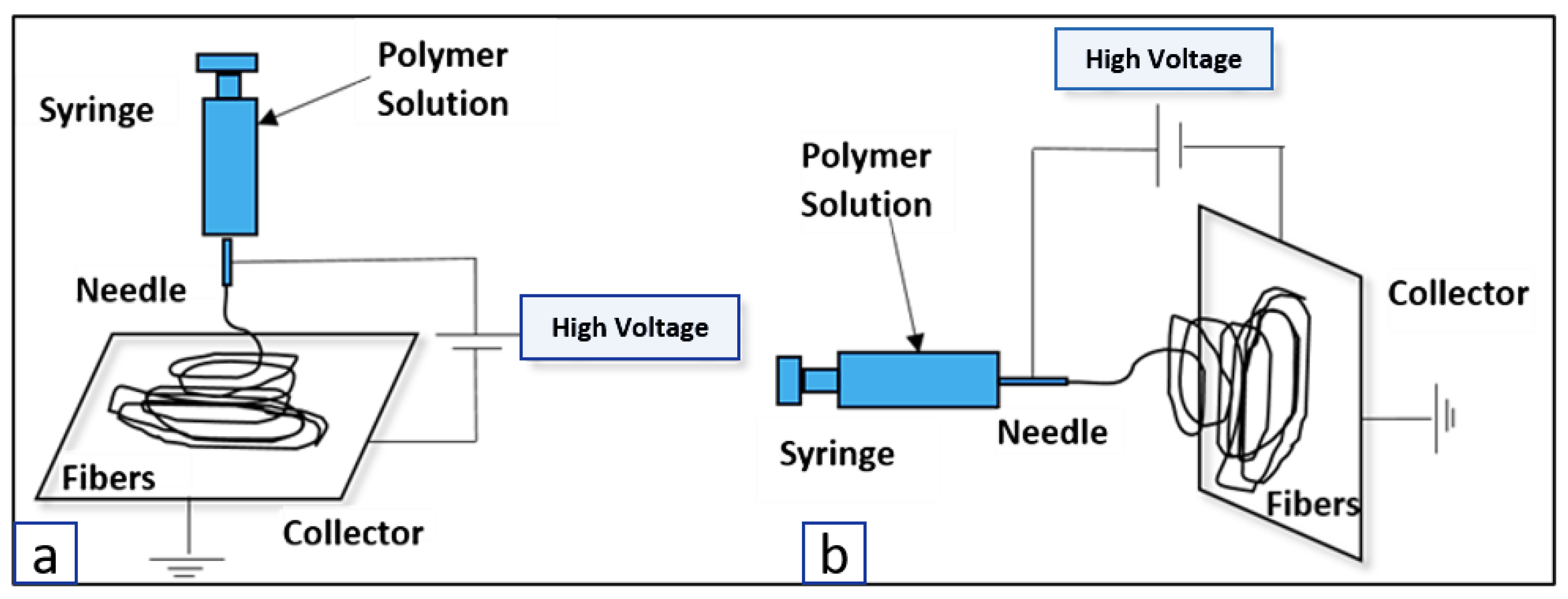
1.2. Working Principle of Electrospinning

The working principle for electrospinning is shown in the Figure 3. A sufficiently high voltage is applied at the location of the liquid droplets formed at the tip of the needle. The local body of the liquid becomes charged. Electrostatic repulsion counteracts the surface tension. Thus, the droplet is stretched, and at a critical point, a stream of liquid erupts from the surface. The point of eruption is called a Taylor Cone. Sir Geoffrey Taylor developed the equation which shows the relationship between the critical voltage and the surface tension as shown in Equation (1) [16,17].
V c 2 = 4 H 2 L 2 ( ln 2 L R 3 2 ) ( 0.117 γ R )
where V c is the critical voltage, H is distance between the needle tip and the collector, L is the length of the needle with radius R, and γ is the surface tension of the liquid (units: V c   in kilovolts; H, L, and R in cm; and γ in dyne per cm). Afshari (2017) showed that electrostatic forces play a key role on the electrospinning of polymer solutions [18]. As such, the Coulomb’s force is considered as the driving factor for better design. In Equation (2) shown below, F is the Coulomb’s force, k is the constant of proportionality, q 1     and   q 2 are charges, and r is the distance between the charges. In principle, the smaller the distance, the greater the electrostatic force on a charged particle.
F = k q 1   q 2 r 2
When an electric field is applied, the liquid jet ejected from the tip of the nozzle/needle travels on a straight line for a short distance. The diameter of the jet, in the straight line, decreases monotonically with the distance from tip, after that a radially outward bending instability happens. The electrostatic force from the charge carries with the jet causes the jet to continue to elongate as it coils and the thin fluid jet solidifies into nanofiber [19].

1.3. Applications of Electrospun Fibers

The typical applications of electrospun fibers include filtration, energy, structures, biomedical, textiles, and others [6] as shown in Figure 4. Other applications include optical and chemical sensors, textiles, reinforcement of composites, health care, and defense and security. Electrospun fibers are projected to play an important role in the development of air filtration, energy storage devices, super-capacitors, and rechargeable batteries [20,21,22,23,24,25,26].
The applications of nanofiber mats in the reinforcement of nanocomposites are discussed by Huang et al. (2003), who executed mechanical characterization of nanofibrous membranes of various polymers and examined their potential applications [17]. Nanofibers can have better mechanical properties than microfibers and therefore superior structural properties can be anticipated. Jiang et al. (2018) provided an overview of nanofiber composite application [27]. Bergshoef and Vancso (1999) showed that smooth nylon-4, six electrospun fibers with diameters in the range of 30–200 nm can be produced from formic acid solutions. These fibers demonstrated reinforcement of transparent composites with an epoxy matrix [28]. Highly porous nanofibers with pore interconnectivity and relatively uniform pore distributions improve membrane performance in the application of desalination (water filtration) [29]. The large surface area of the constituent fibers provides high functionalization capability and mechanical bonding to limit delamination between laminae [30]. Biomedical applications include tissue engineering scaffolds, wound dressing, drug delivery [31], and creation of artificial blood vessels. The non-woven nanofibrous mats produced by electrospinning techniques mimic the extracellular matrix components.
Some important issues and challenges in the 21st century are addressed by using electrospun fibers in the domains of tissue regeneration, energy conversion and storage, and water treatment. Large surface areas, high porosity, and the unique mat structure of electrospun nanofibers have provided improvements over the last decade in the fields of tissue regeneration (skin [32,33,34], nerve [35,36,37], heart [38,39,40], and bone [41,42,43]), energy conversion and storage (solar cells [44,45,46,47], fuel cells [48,49,50,51], and batteries [52,53,54,55]), and water treatment (adsorption [56,57,58], photocatalysis [59,60,61], and filtration [62,63,64]). Potential applications and promising advantages are overviewed by Bhardwaj and Kundu (2010), who highlighted more than 200 polymers that are electrospun for various applications. Teo and Ramakrishna (2006) gave a detailed review on electrospinning design and nanofiber assemblies [65].

1.4. Recent Review Papers on Electrospun Nanofiber

Table 1 lists twelve recent review papers on electrospun fiber applications and characterizations. Of the papers considered, reviews of applications dominate the literature, are a few on mechanical, energy, medical, and processing characterizations. However, there is little work found in the literature on dielectric and mechanical properties together that should contribute to both composite reinforcement and energy applications.

1.5. Parameters and Parameter Optimizations

Important parameters that affect the quality of electrospun fibers formed from polymer solutions can be categorized as solution-specific parameters, process-specific parameters, and environmental-specific parameters [6,17,71].
(a)
Solution parameters: The solution-specific parameters include viscosity, polymer concentration, surface tension, conductivity, and evaporation rate of solvent [18,72,73,74,75,76]. It is observed that low viscosity is typically responsible for bead generation and significant increase in fiber diameter. A similar conclusion was made on polyacrylonitrile/dimethylformamide (PAN/DMF) solution where beads were easier to form at low concentration of 5 wt.% than that formed at higher concentration of 7 wt.% [77,78]. Typically, viscosity and concentration are directly proportional to each other [79]. Additionally, polymer concentration directly controls fiber diameter [79]. In general, an increase in fiber diameter can be achieved by increasing the polymer concentration. Higher surface tension causes bead formation and reduced surface tension favors smooth fiber formation [80].
(b)
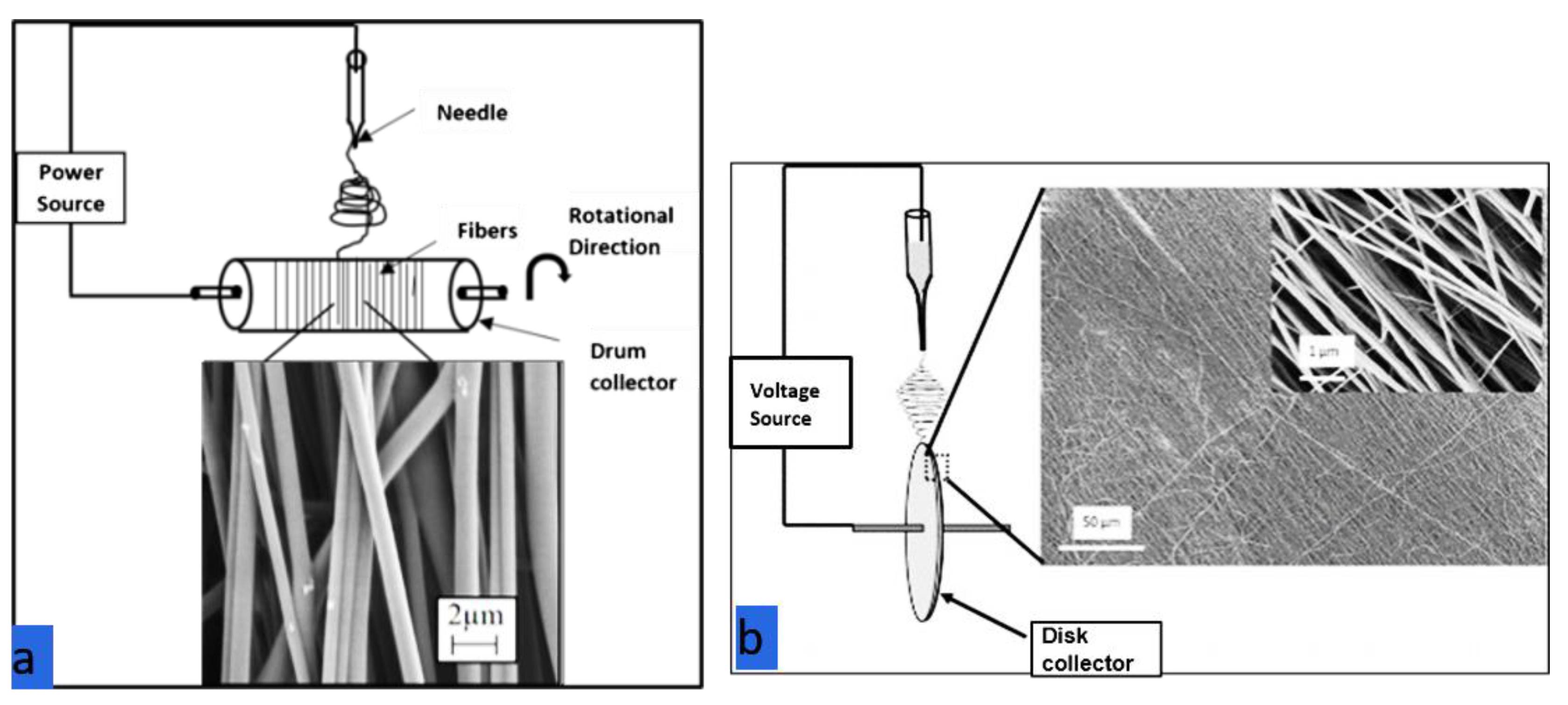
Process parameters: Applied voltage, distance between the nozzle tip and collector, rotating speed of the collector (if drum is used), and solution feed rate are the parameters that are regarded as process specific [18,81,82,83]. In general, fiber diameter can be reduced by increasing applied voltage and vice versa. If the applied voltage reaches a critical value, a charged jet initiates the electrospinning process. This critical voltage is closely related to surface tension of the solution. Lee et al. (2003) reported that there was a linear relationship between voltage applied and surface tension of polystyrene (PS) dissolved in a mixture of tetrahydofuran and DMF [84]. The distance between the tip and the collector mainly controls fiber solidification because a minimum distance is required to allow the fibers sufficient time to dry before reaching the collector. Distances that are too close or too far can cause beads to form. Fang et al. (2010) studied 7 wt.% PAN/DMF electrospun at 2–10 cm away from nozzle tip. The experiments concluded that beads were producing until the distance reached 7 cm [78]. Longer distance between nozzle tip and collector produced bead free fibers.
(c)
Environmental parameters: Humidity and temperature are treated as environment-specific parameters [18,85,86]. According to De Vrieze et al. (2009), the evaporation rate increases with increase in temperature [87]. Moreover, the viscosity of solution generally decreases with an increase in temperature. As the humidity increases, the average fiber diameter increases.
Parameter optimization: Formation of nanofibers involve many input parameters, as mentioned above, to evaluate outputs such as fiber diameter, tensile strength, modulus, and dielectric properties of nanofibers. Parameter optimization helps to achieve desired outputs by tailoring the input parameters. One among the many mathematical modeling techniques for parameter optimization is Design of Experiment (DoE), which is an approach that helps to find the relationship between different inputs over outputs. Parameter optimization based on applied voltage and concentration has been studied by using the DoE approach by Gu et al. (2005) [88]. The study concluded that concentration of solution played an important role to the diameter of nanofibers. Gu et al. (2005) used two factors and four and three respective levels for finding average fiber diameter. Senthil and Anandhan (2005) examined three variables and seven, four, and three respective factor levels for finding the average fiber diameter [89]. Isaac et al. (2018) used DoE approach with two factors and three levels for optimizing the two outputs, namely, specific dielectric constant and specific mechanical strength [90,91]. A mathematical modeling, including the leaky dielectric model which describes the deformation of a Newtonian drop in an electric field and whipping model which depicts the interaction between the electric field and fluid properties for electrospinning processes, has been portrayed by Rafiei et al. (2013) [92]. Ismail et al. (2016) developed a model for stable region and unstable region in the jet propulsion stream for predicting the fiber diameter [93]. Rafiei et al. (2014) modeled and simulated viscoelastic elements for jet propulsion to predict and improve control of nanofiber diameter [94]. Modeling electrospinning of nanofibers for short-range and long-range electrostatic interactions, using a discrete slender model, was conducted by Kowalewski et al. (2009) [95]. The whipping instability in the unstable region of the electrospinning jet propagation has been studied in three polymeric solutions by Kowalewski et al. (2005) [96]. The fiber gets stretched into fractions of initial diameter at the instability region. Ghaly (2014) modeled the electrospinning jet with an inkjet printer technique, using computer-aided fluid/multi-physics/multi-phase flow simulations in COMSOL multiphysics software [97].

2. Molecular Orientation and System Configurations of Nanofibers

Two key factors affecting mechanical and dielectric properties are (a) molecular orientation due to elongation of fibers on the periphery of the rotating mandrel [98] and (b) system configuration improvement for obtaining improved properties due to better alignment [99]. Other properties, such as thermal and electrical properties [100] are also often improved by alignment.

2.1. Molecular Orientation of Nanofibers

High orientation of polymer molecular chains along the fiber axis and aligned electrospun fibers have important consequences in the field of carbon fiber-reinforced nanocomposites. The electrospun fibers are generally stronger than traditional fibers because of their higher orientation of macromolecular polymer chains along the fiber axis. The polymer jet under the influence of an electrostatic field experiences a high degree of molecular orientation due to high elongation strains and shear forces. As explained later, in Section 2.2, System Configuration to Align Fibers, optimal speed of fiber collecting drum brings about better alignment. In addition, optimal speed of collecting drum causes maximum molecular orientation. Beyond the optimal speed, the orientation can decrease slightly. According to Fennessey and Farris (2004), twisted yarns of higher degree of molecular orientation resulted in better mechanical properties [99]. The degree of orientation can be quantified by the X-ray diffraction analysis of the samples. The nitrile group in PAN is oriented in approximately perpendicular to the draw direction. The absorbance of perpendicular polarization showed nitrile-stretching vibration with strong dichroism, and therefore better orientation. A twist angle of 11° in as-spun PAN fiber improved the initial modulus and ultimate strength of 2.6 GPa and 56 MPa, respectively, to 2.2 times and 2.9 times, respectively. Molecular orientation results in better mechanical properties in general, Young’s modulus in particular, of the resulting carbon fibers [101,102]. Baji et al. (2010) studied the effects of electrospun polymers on oriented morphology and tensile properties. The lower the diameter of the fibers, the higher the modulus and strength of the fibers. They observed that finer fibers have enhanced properties because of gradual ordering of molecular chains and increase in crystallinity [103]. Baji et al. (2010) noticed that the modulus and tensile properties of polycaprolactone (PCL) fibers increased significantly when the fiber diameter was reduced to below 500 nm. The molecular orientation improves gradually as the fiber diameter is reduced. Moreover, Beese et al. (2013) concluded that electrospun PAN fibers have better mechanical properties at lower diameters [104]. Arshad et al. (2011) observed that the strength of the carbonized nanofibers at 800 °C increased by 100% when the diameter was reduced from 800 to 200 nm [105]. For composite applications, a decrease in diameter of fiber at the nanoscale level can improve mechanical properties as the specific reinforcement area per unit mass increases. Uyar et al. (2009) observed self-aligned bundled fibers of polyphenylene-g-polystyrene/poly (a-caprolactone) (PP-g-PS/PCL) when blended with polystyrene (PS) or polymethyl methacrylate (PMMA). This is because of the unique molecular architecture of PP-g-PS/PCL and its interaction with PS or PMMA [106].

2.2. System Configuration to Align Fibers

In addition to molecular orientation, physical alignment of electrospun fibers contributes to the production of high strength/high toughness fiber reinforced composites [12]. Among the many ways to produce aligned fibers by using an electrospinning technique, drum collection and rotating disk collectors are the two most popular designs, as shown in Figure 5a,b [65,107,108,109,110,111].
In the drum collector method, the drum collector rotates at high speed and the deposited fiber diameter can be controlled based on the rotational speed of the drum [112,113,114]. The linear speed at the surface of the rotational drum should match the evaporation rate of the solvent so that fibers are deposited and taken up on the surface of the drum. At a rotational speed less than the fiber take-up speed, randomly oriented fibers are obtained on the drum. At higher speed, the fiber take-up velocity breaks the fiber, and continuous fibers are not collected. Therefore, the optimal speed of the rotating drum that matches the evaporation rate is required for maximum alignment [115].
In the rotating disk collector, higher alignment is possible but the production rate is lower because fibers are effectively deposited at only a small area at the disk edge. Theron et al. (2001) reported a conical and an inverted conical instability region of polyethylene-based polymer nanofibers. These finer fibers with diameters ranging from 100 to 300 nm got aligned and wound on a sharp edge disk wheel-like bobbin [116].
Other collection methods that are suitable for fiber alignment are the parallel conductor method, the wire drum collector method, and the wheel rotor collector method as shown in Figure 6a–d. In the parallel conductor method [117,118,119,120], the length of aligned fibers is restricted by the distance between conductive stripes as shown in Figure 6a. Jalali et al. (2006) reported the fundamental parameters affecting the uniaxially aligned PAN nanofibers. The best alignment of nanofibers with a specific gap distance depends on concentration, voltage, and tip to collector distance. As shown in Figure 6b, a bundle collector is moved across the gap to another side for depositing bundle of nanofibers. The best alignment was formed between 10 and 15 wt.% solutions. Uniaxially aligned fibers formed had an aspect ratio (l/d) of higher than 5000 and these fibers are useful in composite reinforcement application. Fryer et al. (2018) studied the effect of alignment on fiber modulus, using the electrostatic gap method. Aligned polyethylene oxide (PEO) fibers have a higher modulus than the non-aligned fibers of similar diameter [121]. Cai et al. (2017) provided an insight in to fabricating ultra-long polyvinylidene fluoride (PVDF) fibers. Here, parallel conducting U-shaped collectors are used to fabricate fibers [122]. According to Lei et al. (2018), more than a meter long aligned PVDF nanofibers were fabricated by using gap electrospinning, where the needle is connected to positive power supply and the parallel plates are connected to the negative power supply [123]. Yang et al. (2007) demonstrated a method that generates parallel fibers, using magnetic-particle-doped polymers in two parallel placed magnets. The magnetic field guides the magnetized electrospun polyvinyl alcohol (PVA) fibers to align in a parallel fashion [124]. Park and Yang (2011) built uniaxial aligned PCL fibers by introducing an inclined gap into dual collectors that consisted of two conductive stripes which were arranged vertically and horizontally [125]. Dabirian et al. (2009) used a hollow metallic cylinder with needle placed at the center of the cylinder. Fibers produced by this method are claimed to be well aligned and spread over large area [126]. Next, in the wire drum collector method, shown in Figure 6c, fibers are deposited without the need for high speed rotation [126]. However, aligned thick films are not possible with this method. Finally, a wheel rotor collector, as shown in Figure 6d, provides elongation strain and therefore more strength to the fibers. However, the many electrodes on the rotating wheel complicate apparatus design [127]. The limitations of other methods imply that drum collection is more likely to be scalable to commercial capacities than other electrospinning methods for fiber alignment. Despite the simplicity of the electrospinning methodologies, industrial applications are relatively rare due to low fiber throughput for existing fiber collection methods. This throughput limitation could be addressed with larger drum sizes and other innovations.
In addition to the design methods mentioned above, there a few unconventional design configurations for aligning fibers. Grasl et al. (2013) developed a technique, using two parallel rotatable auxiliary electrodes applied with time-varying square wave potential, which led to aligned fiber-deposition of PEO [131]. Lei et al. (2017) used a collecting system consisting of insulating hollow cylinder and grating-like electrodes for aligning PVDF fibers, using whipping instability [131]. Khamforoush and Mahjob (2011) used a modified rotating jet method for aligning fibers. The degree of alignment enhanced by more than two times and the average amount of produced fiber is 40% more than that of the simple rotating jet method [132,133].

3. Mechanical and Dielectric Properties of Nanofibers

Carbonaceous materials such as carbon black, fullerene, carbon nanotubes, carbon nanofibers, and graphene extend the functionalities of polymers from lightweight and cost-effective to new applications such as electrically and thermally conductive, electromagnetic shielded, etc. With ever-increasing utilities of multifunctional polymer composites applicable in the electronics, sensors, energy, automobile, and aerospace industries, the mechanical properties and electrical are among the two most important parameters to determine the performance of polymeric nanocomposites [70].

3.1. Mechanical Properties

Among many nanofibers that have mechanical properties, PAN nanofibers are widely preferred because of their excellent tensile strength and modulus. In this section, mechanical properties of PAN nanofibers (in general) and carbon nanofillers are discussed. The mechanical properties of electrospun nanofibers, including PCL, polyvinyl pyrrolidone (PVP), and PEO, are also reviewed. Post-treatment techniques, such as drawing and annealing processes, are discussed, since these post-treatments can improve molecular orientation and crystallinity [134]. Moreover, PAN nanofibers in composite applications and other types of nanofibers are discussed in the end.

3.1.1. PAN Nanofibers and Carbon Fillers

Edie (1998) reported that PAN-based carbon fibers have higher tensile strengths and reasonable tensile moduli compared to pitch-based carbon (micro-size) fibers [135]. PAN precursor is used for carbon nanofiber (CNF) production in nanocomposite structures [136] and in energy storage devices [137] due to their good electrospinning property, high carbonization yield, excellent nanostructure, ultrahigh specific surface area, good electrical conductivity, and stability. PAN is soluble in polar solvents like dimethylformamide (DMF), dimethylsulfone (DMSO2), dimethylsulfoxide (DMSO), and dimethylacetamide (DMAc) [13]. Among organic solvents, DMF and DMSO are known to be good solvents of PAN and for production of high-performance PAN fibers, DMSO is preferred [138].
Chawla et al. (2017) observed that carbon nanofibers obtained from hot-drawn samples demonstrated strength as high as 5.4 GPa and modulus 287 GPa as shown in Figure 7a,b. Here, 400 nm PAN nanofibers reached a maximum strength (5.4 GPa) after hot-drawn and carbonized at 1100 °C [139].
As shown in Figure 8a, the thinnest fiber had the highest strength when compared to other thicker fibers. Moreover, it is evident from Figure 8b that the thinnest fiber had the highest modulus. Papkov et al. (2013) [140] studied simultaneous improvement in strength, modulus, and toughness in ultrafine as-spun PAN electrospun nanofibers as shown in Figure 8a,b. A reduction of as-spun PAN nanofiber diameter from 2.8 μm to 100 nm resulted in higher modulus, strength, and toughness. The 100 nm annealed PAN fibers showed a modulus of 48 GPa and strength of 1.75 GPa. This study recorded dramatic increase in strength and modulus for nanofibers finer than 200–250 nm.
Beese et al. (2013) [104] compared the result with Arshad et al. (2011) [105] and showed the dependence of fiber diameter on strength and modulus as shown in Figure 9. As the fiber diameter decreases, the tensile strength and modulus increase. Beese et al. (2013) observed that individual PAN nanofibers with 108 nm in diameter, heat treated at 800 °C, showed a maximum modulus of 262 GPa and strength of 7.3 GPa.
Arshad et al. (2011) [105] showed that individual PAN nanofibers with 9 wt.% and other given parameters had the stress–strain relationship shown in Figure 10. The plot shows a linear relationship until 125 MPa and thereafter a strain hardening region where crystallinity occurs. The maximum ultimate strength was found with 1 kV/cm and 430 nm in diameter. Arshad et al. demonstrated that increase in carbonization temperature in CNFs monotonically increases elastic modulus, while highest strength of CNFs was observed at a carbonization temperature of 1400 °C. This study revealed the fiber diameter and carbonization temperature had effect on strength and modulus of PAN nanofibers.
Wan et al. (2015) [1] reported that tensile strength of carbon nanofiber mats can be approximately estimated as the sum of individual nanofibers as shown in Figure 11. The nanofiber mat reached their maximum strength where the curves dropped sharply, which means the majority of nanofibers break simultaneously. Wan et al. (2015) showed that a quantitative relationship exists between the tensile strength of a nanofiber mat and that of individual nanofibers as in Figure 12. The tensile strength of nanofiber mat is described by Equation (3).
σ = ( 1 P ) ( θ + s i n θ c o s θ ) 2 2 π s i n θ σ f
where σ f is the fiber strength and θ is the diagonal angle of fibers to the longitudinal axis of loading. The value of θ can be obtained from L = D cosθ and W = D sinθ, where L, W, and D are the length, width, and diagonal of rectangular tensile testing specimen. According to Wan et al. (2015), tensile strength is also a function of the porosity of a nanofiber mat as shown in Figure 13. Specific tensile strength is calculated by using Equation (5). Fiber volume is determined by using Equation (4).
σ sp = σ ρ ( 1 P )
ρ is the fiber density and P is the porosity.
  V f = V m ( 1 P )
V m is the volume of mat and P is the porosity.
Zhang et al. (2016) reported that carbon nanofibers are used in reinforcement of nanocomposites [12]. A carbon nanotube (CNT) is one of the allotropes of carbon. According to Naebe et al. (2010), electrospinning of CNT/polymer has been shown to induce alignment of nanotubes within the matrix. Electropsun CNT/polymer nanofibers showed significant improvement in fiber strength, modulus, and conductivity [141]. One dimensional CNF and CNT have high aspect ratios (typically over a few hundred) that enable them to form a conductive network and they possess excellent mechanical properties. According to Zhang et al. (2016), CNF, compared to CNT, exhibits good dispersion and low fabrication cost. CNT has excellent electrical conductivities, a large surface area to volume ratio, and structural stability [12]. As noticed by Chung (2016), CNT and CNF are difficult to disperse and bond relatively weakly in a matrix. The large area of interface associated with small diameter CNT and CNF aggravate the issue [142]. Addition of small amount of CNT’s in PAN precursor nanofibers can improve graphitic order and mechanical properties of carbon nanofibers [143,144]. Both single-walled carbon nanotube (SWCNT) and multi-walled carbon nanotube (MWCNT) [145] can be used as fillers in PAN to enhance molecular orientation. Two types of MWCNT are possible; one is long MWCNT and the other is short MWCNT. Short MWCNTs are 0.5–2 µm in length and the diameter could be 30–50 nm. Graphene is another nanofiller used as a reinforcing material. Compared to CNT and graphene, CNF is considered as a promising reinforcement material due to its relatively high mechanical performance and low fabrication cost. Adding fillers to precursor nanofibers improves tensile strength and tensile modulus as evident in the session, drawing process below.

Drawing Process

Hot drawing of polymers is achieved by drawing the precursors at temperature above the glass transition temperature. Chawla et al. (2017) successfully carried out hot-drawing of PAN electrospun ribbons to enhance molecular orientation. PAN nanofiber ribbons were hot-drawn to two times and four times their original length. These ribbons were further stabilized at 250–300 °C and then carbonized at 1100 °C for 1 h. The tensile modulus and strength of four times hot-drawn ribbons showed maximum values of 287 and 5.4 GPa, which are 71% and 111% increment respectively as compared to as-spun electrospun CNFs. Cai and Naraghi (2019) studied the templating effect of functionalized SWCNTs in CNFs and the contribution of that to mechanical properties of CNFs. To enhance the packing of polymer chains of the precursor around CNT’s, PAN as-spun electrospun fibers were subjected to thermomechanical processing (hot-drawing). The MEMS-based single-nanofiber mechanical testing result showed a strong relationship between the modulus, strength improvement and hot-drawing process. The average tensile strength and modulus of CNF/SWCNT were measured to be 7.6 ± 1.72 and 268 ± 29 GPa respectively [146]. Polyamide (PA) fibers are undergone post-drawing process to obtain moderate molecular orientation and crystallinity. After the post-drawing process, PA is found to be with good mechanical strength and abrasion resistance [134]. Yu et al. (2020) revealed enhanced effect of graphene oxide (GO) in PAN nanofiber yarns. The alignment of PAN chains and GO in nanofibers was enhanced by hot-drawing which resulted in increased orientation induced crystallization [147]. Peng et al. (2019) experimentally found that hot-drawn polyethylene fibers with decreasing fiber diameter, Young’s modulus increase rapidly. That is due to the fact that chain orientation parameter increases with increasing hot-drawing ratio [148]. Inai et al. (2006) reported that higher rotational speed of fiber collecting disc and post-processing such as annealing and hot-drawing on molecular structure of PLLA nanofibers improved crystalline structure orientation and mechanical strength of fibers. Better mechanical properties were found at higher hot-drawing ratio [149]. Isotactic polypropylene (iPP) nanofibers with the diameter range of 75–375 nm were made from the blends of cellulose acetate butyrate (CAB) and iPP with a ratio of 97.5–2.5. The hot-drawn nanofibers with the ratio of 25 resulted in lower crystallinity than that of bulk iPP. The increase in the amount of CAB in blends gave rise to higher crystallinity in iPP fibers [150].
Cold drawing of polymers is normally done below the glass transition temperature. Cold-drawn nanofibrillated cellulose nanopaper increases its modulus and strength from 10 GPa and 185 MPa to 24.6 GPa and 428 Mpa, at the draw ratio of 1.6 [151]. Cold-drawn blend fibers of PVA and PTFE increased the degree of crystallinity in PTFE/PVA fibers [152]. The addition of hydroxyethyl cellulose (HEC) in cellulose nanofiber improved mechanical property. An aqueous solution of low concentration cellulose nanofiber with HEC promoted nanofiber alignment which was further improved by cold drawing [153].

3.1.2. Other Electrospun Nanofibers

In this session, Alarifi et al. (2009) reported the mechanical property of a PAN-derived carbon nanofiber composite and the effect of molecular orientation along the fiber direction [154]. The study placed electrospun carbonized PAN nanofibers on a stacking sequence of 0, 45, −45, and 45 to create a laminate of ten plies. The tensile testing of PAN-derived carbon nanofiber composites revealed that they possess a high elastic modulus due to stabilization at a high temperature (280 °C), for 1 h, in an oxygen atmosphere. Thermogravimetric analysis (TGA), dynamic mechanical analysis (DMA), thermomechanical analysis (TMA), and differential scanning calorimetry (DSC) analyses confirmed that the nanofibers were crystalline and had good mechanical and thermal properties. Thinner nanofibers have larger surface-area-to-volume ratios. Therefore, thinner fibers have better mechanical integrity between the matrix and the surface of the reinforcing agent for effective load transfer in composites. Baji et al. (2010) proved that as the PCL fiber diameter reduces, the tensile strength and modulus increase [103]. Figure 14a shows the tensile strength and modulus versus fiber diameter. For fiber diameters greater than 2 µm, both tensile modulus and tensile strength appear not to change with diameter. The degree of crystallinity increases gradually as the PCL fiber diameter is reduced as shown in Figure 14b. As for polymers, in general, an increase in the degree of crystallinity increases the density, stiffness, strength, and toughness [155]. Huang et al. (2016) showed that with the addition of conductive filler materials, the diameter of fibers reduced due to increasing composition of PVP/cellulose nanocrystal (CNC)/silver particle [156]. The addition of CNC increased the tensile strength.
The mechanical properties of different nanofibers are shown in Table 2. According to Kancheva et al. (2015), the mechanical strength of various combinations of polylactic acid (PLA) and PCL mats was reported to be enhanced after thermal treatment at 60 °C. The melting of PCL enabled the sealing of the fibers, thus enhancing the mechanical properties of mats [157]. Wang et al. (2004) reported an increase in modulus of silk/PEO fibers from as-spun to methanol-treated and to water-extracted fibers [158]. The mechanical properties of single fibers were characterized by AFM nanoindentation. Tan et al. (2005) studied tensile property, using an approach that uses an atomic force microscope tip to stretch a single electrospun PEO nanofiber. The elastic modulus of PEO nanofiber was found to be 45 MPa [159]. Lin et al. (2012) demonstrated characterization of mechanical properties of ultra-thin electrospun polymer fibers. Electrospun techophilic, tecoflex, nylon 6, PVP, and PEOX fibers were captured directly on the testing device, stretched at controlled rates, and deflected with forces created by different velocities of streams of air [160].

3.2. Dielectric Properties

In this section, the dielectric properties of PAN fibers, carbon nanofillers, and other electrospun fibers and different nanomaterials are discussed. According to classical theory, the dielectric constant (k) is defined as the ratio of the permittivity (E) of a substance to the permittivity of free space (E0). Values of k are always greater than or equal to 1. For most polymers, k values are in the range of 2 to 10.

3.2.1. PAN Nanofibers and Carbon Fillers

According to Li et al. (2010), the dielectric property depends on porosity and density [2]. The Figure 15 shows the dependence of density and porosity of PAN nanofiber membranes at the frequency of 1 MHz. The dielectric constant gradually increases with density ranging from 0.164 to 0.182 g/cm3. Moreover, the dielectric decreases with increasing porosity from 84.4% to 86.1%. The apparent porosity can be found by Equation (6). Figure 16 shows the dielectric constant of PAN at 8 wt.% in the radio frequency range.
P   ( % )   =   ( 1   ρ M ρ P ) * 100
where P is the porosity, ρ M is the membrane density, and ρ P is the polymer density.
Khan et al. (2014) reported the dielectric constant of PAN and PMMA as a function of graphene nano flakes as in Figure 17. The physical properties, including the dielectric constant, were significantly increased with graphene concentrations [161].
According to Im et al. (2011), the increase in dielectric property of permittivity increases the electromagnetic interference shielding effectiveness (EMI-SE), as shown in Figure 18a,b. The permittivity of carbon fibers with different proportions of ZrO2 is shown in Figure 18a, and the EMI-SE of the same proportions is shown in Figure 18b. This relationship is more evident below 2000 MHz [162].
Among many conventional carbon fillers, CNTs have been preferred for high dielectric constant. Bhattacharya (2016) gave a detailed review of processing of CNTs as potential nanofillers to form nanocomposites [163]. CNFs have been widely used in electrochemical energy storage devices as reviewed by Zhang et al. (2016) [12]. Electrospun polymer/CNF or CNT fibers have been used in energy storage devices. The comparison between the CNF and CNT is shown in Table 3.

3.2.2. Other Electrospun Fibers and Nanoparticles

The dielectric properties of different nanofibers are shown in Table 4. Lee et al. (2003) studied that dielectric constant strongly depends on solvent content and diameter of PCL electrospun fibers. As the solvent content increases, the fiber diameter decreases and dielectric constant increases [164]. Wei et al. (2014) reported the dielectric characterization of annealed electrospun BaTiO3 fibers. Crystallized BaTiO3 nanofibers showed better dielectric permittivity [165]. Electrospun PVDF fibers have higher β-crystalline content which enhances the piezoelectric property and its energy-harvesting application. Jabbarnia et al. (2016) reported various electrospun PVDF/PVP mats fabricated with different percentages of carbon black nanoparticles for the applications such as supercapacitor separators and other energy storage devices. The dielectric constant values were increased with the carbon black loading [166]. Lee et al. (2016) studied the effect of Fe and Co mixed with PVP. The analysis of FE-SEM images of electrospun products obtained by using solutions with and without citric acids was carried out. The composite showed excellent electromagnetic (EM) wave absorption properties where the power loss of the FeCo nanofibers increased to 20 GHz [167]. EM waves with frequencies in the microwave range of 12 to 18 GHz are widely used in wireless communication networks, radar systems, military aircraft, and satellite communication devices. Wang et al. (2011) studied that an increase in dielectric constant was achieved in a combination of high aspect ratio barium titanate (BaTiO3) and graphene platelets in a silicon rubber matrix compared to their spherical counterparts. Higher volume fractions of ferroelectric particles lead to increased dielectric constant but also to lower mechanical properties. Composites with high aspect ratio fillers at lower loading exhibit higher dielectric constant [168]. Issa et al. (2017) reported an increase in permittivity by the addition of silver nanoparticles (AgNP) in PVDF. This is due to the interfacial polarization associated with entrapment of free charges generated at the interfaces between the AgNPs and PVDF [4]. Anita and Natarajan (2015) studied the potential of ZnO nanopowders with PVA matrix for the use of UV shielding [169].
The in situ sol–gel method (ISM) and direct deposition method (DDM) have been discussed to analyze the effect of UV shielding. The ISM–PVA/ZnO composite showed better UV absorption in optical transmission measurements due to the uniform dispersion of the ZnO in the fibrous matrix. Kim et al. (2016) analyzed the EMI-SE of multiwalled carbon nanotube (MWCNT) reinforced polyurethane (PU) in the DMF with tetrahydrofuran solvents and coated with conductive poly(3,4-ethylenedioxythiophene) (PEDOT) [170]. The EMI-SE from a network analyzer shows 25 dB at the frequency range of 50 MHz–10 GHz.

4. Applications of Aligned Fibers

The authors of this paper, Isaac et al. (2017), observed improvements in the mechanical strength and dielectric strength with increase in degree of alignment of fibers [171]. Aligned fibers are greatly beneficial when they are used in applications including field effect transistors, gas and optical sensors, fiber reinforced composite materials, and tissue engineering [172,173]. Bashur (2009) discussed the application of aligned fibers in the field of tissue engineering [174]. Moreover, Lawrence and Liu (2006) and Katti et al. (2004) stated that there are other applications found in the variety of areas if the fibers are in aligned form [175,176]. This section discusses mechanical and dielectric applications of aligned electrospun fibers.

4.1. Influence of Aligned Fibers on Mechanical Properties of Nanofiber Mats

Hou et al. (2005) showed that well-aligned, multi-walled carbon nanotubes (MWCNT) can improve the mechanical properties of a PAN-based nanofiber mat [177]. Kannan et al. (2007) demonstrated that electrospun polymer/CNT leads to nanocomposite fibers with embedded CNTs orienting parallel to the nanofiber axis [178]. Moreover, alignment of CNTs in the fiber direction can improve thermal conductivity [179]. Dhakate et al. (2016) reported that semi-aligned electrospun carbon nanofiber composites show excellent bending strength and interlaminar shear strength [180]. High-performance aramid copolymer fibers underwent four treatment factors. Among them, the degree of stretching after coagulation resulted in high degree of molecular orientation. The increased tensile strength of aramid fibers improved the cut resistance of aramid fibers, and therefore can be used in cut protection [181]. Ultra-high molecular weight polyethylene fibers with the tensile strength of 1.5 GPa were successfully prepared and structure and tensile property were studied. The increase in draw ratio improved the crystallinity of ultra high molecular weight polyethylene fibers. The molecular orientation degree increased, and tensile property also improved [182]. Increasing the draw-ratio resulted in an increased molecular orientation, Young’s modulus, and tensile strength of poly(amide-block-aramid) fibers comprised of alternating rigid aramid blocks of poly(p-phenylene terephthalamide) (PPTA) and flexible blocks of polyamide 6,6. Heat treatment at 300 °C of the fibers resulted in an increase of Young’s modulus and minor increase of strength [183].
Aligned micro scale fibers (7µm diameter) have application in composite reinforcement. There is increased need to manufacture complex composites for light weight applications. Carbon/epoxy composites have greater application in aircraft, sports cars, and space crafts because of a better strength to weight ratio than that of metals like aluminum alloys. They are thermally stable because of the lower coefficients of thermal expansion properties of carbon fibers. Yu et al. (2014) showed that short carbon fiber composites can be used in places where complex shapes and ductile properties are required [184]. Short carbon fibers, with an aspect ratio of 400, resulted in composites with a tensile modulus of 119 GPa and strength of 1211 GPa.
Compton and Lewis (2014) reported that cellular composites with controlled alignment of multi-scale and high aspect ratio fibers can result in reinforcement of hierarchical structures [185]. They demonstrated the first 3D printed cellular composites composed of oriented fiber-filled epoxy with exceptional mechanical properties. Malek et al. (2017) developed a new carbon fiber reinforced epoxy for 3D printing which resulted in printing materials with longitudinal Young’s modulus up to 57 GPa [186].

4.2. Influence of Aligned Fibers on Dielectric Properties of Nanofiber Mats

Ning et al. (2014) showed that aligned MWCNT/PVA has high dielectric constant, low dielectric loss, high breakdown strength, and high energy density. These properties contribute in applications such as artificial muscles, energy storage, flexible electronics, and sensors [187]. Aligned MWCNT/PVA composite films were prepared by using electrospinning in situ film-forming technique. Additionally, Liu et al. (2012) confirmed the tailoring of dielectric property by controlling the alignment of CNTs [187]. Ma et al. (2012) reported that aligned PVDF had better molecular orientation than its random fiber counterparts. This is because of the smaller diameter of the aligned fibers. These nanofibers have applications in the field of sensors and actuators [188]. Agarwal et al. (2009) reported that aligned fibers have applications in nanofluidics, superhydrophobic patterning, nanoelectronics, and nanophotonic circuits [189]. Edmondson et al. (2012) demonstrated the significance of fiber alignment in improving the piezoelectric property, using centrifugal electrospinning. PVDF and PEO have piezo-, pyro-, and ferro-electric properties, and these aligned fibers can provide for applications in actuators, transistors, textiles, and composites [190]. P. Kumar et al. (2017) showed that aligned graphene films improved EMI shielding. Electromagnetic (EM) waves cause interference or device malfunction and also can cause harm to human bodies [191]. Song et al. (2013) observed that aligned carbon-based fillers enhanced EMI shielding. The alignment produced anisotropic characteristics that achieve enhancement in absorption and reflection performance [192].

5. Electrospinning System for Dielectric and Mechanical Property Studies

The authors of this paper, Isaac et al. (2017) studied the effect of electrospun fiber alignment on mechanical and dielectric properties, using a setup designed and drawn in 3D modeling software, as shown in Figure 19. The electrode, mandrel holding sheet, acrylonitrile butadiene styrene (ABS) sheet for adjusting the distance between needle tip and mandrel, and the sliding front door are shown above. The final physical setup of electrospinning device is shown in Figure 20.
The whole apparatus is placed under a fume hood, for safety purposes, so that any toxic solvent escapes through the fume hood. Using this setup, electrospun fiber mats were fabricated, fiber morphology was analyzed, and tensile and dielectric properties were characterized.

5.1. Material Builds

PAN/DMF solution was prepared with 8 wt.% concentration. The electrospinning device ran for ten minutes in order to form sufficient fibers on the aluminum foil wrapped on the mandrel. Figure 21a,b shows the fiber mat formed on the mandrel and the fiber mat unfolded from the mandrel.

5.2. Fiber Morphological Analysis

The electrospun fiber mat formed was examined under a NanoSEM 230 SEM microscope to measure fiber diameter. As shown in Figure 22a,b, the fiber diameter decreases as the needle size decreases from 18G to 22G. The feed rate was 0.3 mL/h. The 18G needle produced fibers with average diameter of 1 µm, whereas the 22G needle produced fibers in the range of 300 to 900 nm diameters with an average diameter of 600 nm. The smaller the fiber diameter, the better the mechanical properties.

5.3. Tensile and Dielectric Test Results of Electrospun Mats

PAN precursor with DMF solution at 8 wt.% concentration, using a 22G needle, is used for electrospinning. More than thirteen experimental runs were carried out to determine suitable process parameter settings. The three best samples were taken, to analyze the degree of fiber alignment. The tensile and dielectric test results for the three samples are given below in Figure 23a–c. The SEM images are shown in Figure 24.
The SEM image of Sample 1 shows loosely packed nanofibers. Samples 2 and 3 have more closely packed fibers and better alignment of fibers, and Sample 3 has the highest densely packed fibers. These images are viewed at 20 μm magnification. Tensile strengths of Samples 2 and 3 are better than that of Sample 1, since they are better aligned and closely packed. As evident from Figure 23a, Samples 2 and 3 show higher tensile strength, and Sample 1 has the least. Better alignment combined with dense fibers contributed to the better tensile strengths of Samples 2 and 3. Sample 2 shows a tensile strength of 4.47 MPa. As shown below, in Figure 23b, Sample 3 shows the highest dielectric constant. The dielectric constant for Sample 3 is 2.56 Hz at 0.1 Hz. The best parameters are chosen by comparing the three given samples for their SEM images, tensile strengths, and dielectric properties as shown in Figure 23c. Sample 3 gives consistent and uniform fibers. The best parameters at 8 wt.% correspond to Sample 3. The Sample 3 has uniform fiber distribution with the lowest range in diameters. Moreover, the fibers are formed without beads. The tensile strength and dielectric constant of Sample 3 is found to be 4.43 MPa and 2.56, respectively.

6. Future Work

While a few studies have methodically experimented with system parameter optimization for limited sets of parameters, none has studied the nonlinear effects of two or more factors with three levels per factor for obtaining the mechanical and dielectric responses. Consequently, parameter interactions and nonlinearities have were studied, in-depth, to optimize alignment for mechanical and dielectric properties. Very few studies have been conducted on the nanofiber orientation variations along the fiber direction, using a rotating mandrel and its effect on mechanical and dielectric properties. The variability of data in both dielectric and tensile tests needs to be quantitatively addressed, and therefore a modified improved system should be developed. The improved system will lead to consistencies in the behavior of nanofiber specimens and acceptable standard deviations in variability that indicate meaningful parameter levels and trends. Future work will focus on system improvements and methodical experimentation (Design of Experiments), to optimize system parameters for improved mechanical and dielectric responses and application of PAN nanofiber mat materials in advanced mechanical and energy applications. Future research work will determine the nature of the trade-off between mechanical strength and dielectric properties—whether it is linear or non-linear, synergistic, or detrimental.

7. Conclusions

This work has provided a detailed review and analysis of methods for alignment of electrospun fibers and their resulting mechanical and dielectric properties. A key consideration is the molecular orientation of fibers along the fiber direction, as it is important for improvement in mechanical properties. Design configuration options for electrospinning apparatuses were surveyed in order to analyze the ability of each to improve fiber alignment. Given the mechanical and dielectric performance improvement possible with increasing fiber alignment, the need to improve electrospinning apparatus capabilities for fiber alignment is paramount and worthy of further study and experimentation.

Author Contributions

B.I., R.M.T. and K.R. discussed the contribution of electrospinning in various fields and outlined the manuscript with the focus on mechanical and dielectric properties. B.I wrote the manuscript, and R.M.T. and K.R. verified and edited it. All authors have read and agreed to the published version of the manuscript.

Funding

There is no funding for this project.

Acknowledgments

Blesson Isaac would like to thank Robert V. Fox, supervisor at Idaho National Laboratory for his guidance and The University of Texas at Arlington Research Institute for supplying the materials for experiments.

Conflicts of Interest

The authors declare that they have no conflict of interest.

References

  1. Wan, L.Y.; Wang, H.; Gao, W.; Ko, F. An analysis of the tensile properties of nanofiber mats. Polymer 2015, 73, 62–67. [Google Scholar] [CrossRef]
  2. Li, Y.; Lu, X.; Liu, X.; Zhang, C.; Li, X.; Zhang, W.; Wang, C. Ultra-low dielectric performance of polymer electrospun nanofiber mats. Appl. Phys. A 2010, 100, 207–212. [Google Scholar] [CrossRef]
  3. Liu, L.; Lv, F.; Li, P.; Ding, L.; Tong, W.; Chu, P.K.; Zhang, Y. Preparation of ultra-low dielectric constant silica/polyimide nanofiber membranes by electrospinning. Compos. Part A Appl. Sci. Manuf. 2016, 84, 292–298. [Google Scholar] [CrossRef]
  4. Issa, A.A.; Al-Maadeed, M.A.; Luyt, A.S.; Ponnamma, D.; Hassan, M.K. Physico-mechanical, dielectric, and piezoelectric properties of PVDF electrospun mats containing silver nanoparticles. C J. Carbon Res. 2017, 3, 30. [Google Scholar] [CrossRef] [Green Version]
  5. Dwivedi, S.; Sakamoto, S.; Kato, S.; Mitsumata, T.; Kaneko, T. Effects of biopolyimide molecular design on their silica hybrids thermo-mechanical, optical and electrical properties. RSC Adv. 2018, 8, 14009–14016. [Google Scholar] [CrossRef] [Green Version]
  6. Bhardwaj, N.; Kundu, S.C. Electrospinning: A fascinating fiber fabrication technique. Biotechnol. Adv. 2010, 28, 325–347. [Google Scholar] [CrossRef]
  7. Cooley, J.F. Improved Methods of and Apparatus for Electrically Separating the Relatively Volatile Liquid Component from the Component of Relatively Fixed Substances of Composite Fluids. United Kingd. Pat. 1900, 6385, 19. [Google Scholar]
  8. Cooley, J.F. Apparatus for Electrically Dispersing Fluids. U.S. Patents 6,926,31A, 4 February 1902. [Google Scholar]
  9. Morton, W.J. Method of Dispersing Fluids. U.S. Patents 7,056,91A, 29 July 1902. [Google Scholar]
  10. Anton, F. Process and Apparatus for Preparing Artificial Threads. U.S. Patents 19,755,04A, 2 October 1934. [Google Scholar]
  11. Anton, F. Method and Apparatus for Spinning. U.S. Patents 21,609,62A, 6 June 1939. [Google Scholar]
  12. Zhang, B.; Kang, F.; Tarascon, J.-M.; Kim, J.-K. Recent advances in electrospun carbon nanofibers and their application in electrochemical energy storage. Prog. Mater. Sci. 2016, 76, 319–380. [Google Scholar] [CrossRef]
  13. Nataraj, S.; Yang, K.; Aminabhavi, T. Polyacrylonitrile-based nanofibers—A state-of-the-art review. Prog. Polym. Sci. 2012, 37, 487–513. [Google Scholar] [CrossRef]
  14. Luo, C.; Stoyanov, S.D.; Stride, E.; Pelan, E.; Edirisinghe, M. Electrospinning versus fibre production methods: From specifics to technological convergence. Chem. Soc. Rev. 2012, 41, 4708–4735. [Google Scholar] [CrossRef]
  15. Zhang, C.; Feng, F.; Zhang, H. Emulsion electrospinning: Fundamentals, food applications and prospects. Trends Food Sci. Technol. 2018, 80, 175–186. [Google Scholar] [CrossRef]
  16. Taylor, G.I. Electrically driven jets. Proc. R. Soc. Lond. A Math. Phys. Sci. 1969, 313, 453–475. [Google Scholar]
  17. Huang, Z.-M.; Zhang, Y.Z.; Kotaki, M.; Ramakrishna, S. A review on polymer nanofibers by electrospinning and their applications in nanocomposites. Compos. Sci. Technol. 2003, 63, 2223–2253. [Google Scholar] [CrossRef]
  18. Afshari, M. 4.3.1.3 Effect of Electric Charge. In Electrospun Nanofibers; Elsevier: Amsterdam, The Netherlands, 2017. [Google Scholar]
  19. Reneker, D.H.; Yarin, A.L. Electrospinning jets and polymer nanofibers. Polymer 2008, 49, 2387–2425. [Google Scholar] [CrossRef] [Green Version]
  20. Gibson, P.; Schreuder-Gibson, H.; Rivin, D. Transport properties of porous membranes based on electrospun nanofibers. Colloids Surf. A Physicochem. Eng. Asp. 2001, 187, 469–481. [Google Scholar] [CrossRef]
  21. Bruce, P.G.; Freunberger, S.A.; Hardwick, L.J.; Tarascon, J.-M. Li–O2 and Li–S batteries with high energy storage. Nat. Mater. 2012, 11, 19–29. [Google Scholar] [CrossRef]
  22. Goodenough, J.B. Electrochemical energy storage in a sustainable modern society. Energy Environ. Sci. 2014, 7, 14–18. [Google Scholar] [CrossRef]
  23. Peng, S.; Jin, G.; Li, L.; Li, K.; Srinivasan, M.; Ramakrishna, S.; Chen, J. Multi-functional electrospun nanofibres for advances in tissue regeneration, energy conversion & storage, and water treatment. Chem. Soc. Rev. 2016, 45, 1225–1241. [Google Scholar]
  24. Khil, M.S.; Cha, D.I.; Kim, H.Y.; Kim, I.S.; Bhattarai, N. Electrospun nanofibrous polyurethane membrane as wound dressing. J. Biomed. Mater. Res. Part B 2003, 67, 675–679. [Google Scholar] [CrossRef]
  25. Mao, X.; Hatton, T.A.; Rutledge, G.C. A review of electrospun carbon fibers as electrode materials for energy storage. Curr. Org. Chem. 2013, 17, 1390–1401. [Google Scholar] [CrossRef] [Green Version]
  26. Mei, Y.; Yao, C.; Fan, K.; Li, X. Surface modification of polyacrylonitrile nanofibrous membranes with superior antibacterial and easy-cleaning properties through hydrophilic flexible spacers. J. Membr. Sci. 2012, 417, 20–27. [Google Scholar] [CrossRef]
  27. Jiang, S.; Chen, Y.; Duan, G.; Mei, C.; Greiner, A.; Agarwal, S. Electrospun nanofiber reinforced composites: A review. Polym. Chem. 2018, 9, 2685–2720. [Google Scholar] [CrossRef]
  28. Bergshoef, M.M.; Vancso, G.J. Transparent nanocomposites with ultrathin, electrospun nylon-4, 6 fiber reinforcement. Adv. Mater. 1999, 11, 1362–1365. [Google Scholar] [CrossRef]
  29. Ahmed, F.E.; Lalia, B.S.; Hashaikeh, R. A review on electrospinning for membrane fabrication: Challenges and applications. Desalination 2015, 356, 15–30. [Google Scholar] [CrossRef]
  30. Musiari, F.; Pirondi, A.; Moroni, F.; Giuliese, G.; Belcari, J.; Zucchelli, A.; Brugo, T.; Minak, G.; Ragazzini, C. Feasibility study of adhesive bonding reinforcement by electrospun nanofibers. Procedia Struct. Integr. 2016, 2, 112–119. [Google Scholar] [CrossRef] [Green Version]
  31. Mirjalili, M.; Zohoori, S. Review for application of electrospinning and electrospun nanofibers technology in textile industry. J. Nanostruct. Chem. 2016, 6, 207–213. [Google Scholar] [CrossRef] [Green Version]
  32. Sekiya, N.; Ichioka, S.; Terada, D.; Tsuchiya, S.; Kobayashi, H. Efficacy of a poly glycolic acid (PGA)/collagen composite nanofibre scaffold on cell migration and neovascularisation in vivo skin defect model. J. Plast. Surg. Hand Surg. 2013, 47, 498–502. [Google Scholar] [CrossRef]
  33. Kumbar, S.G.; Nukavarapu, S.P.; James, R.; Nair, L.S.; Laurencin, C.T. Electrospun poly(lactic acid-co-glycolic acid) scaffolds for skin tissue engineering. Biomaterials 2008, 29, 4100–4107. [Google Scholar] [CrossRef] [Green Version]
  34. Jin, G.; Prabhakaran, M.P.; Ramakrishna, S. Stem cell differentiation to epidermal lineages on electrospun nanofibrous substrates for skin tissue engineering. Acta Biomater. 2011, 7, 3113–3122. [Google Scholar] [CrossRef]
  35. Mukhatyar, V.J.; Salmerón-Sánchez, M.; Rudra, S.; Mukhopadaya, S.; Barker, T.H.; García, A.J.; Bellamkonda, R.V. Role of fibronectin in topographical guidance of neurite extension on electrospun fibers. Biomaterials 2011, 32, 3958–3968. [Google Scholar] [CrossRef] [Green Version]
  36. Lim, S.H.; Liu, X.Y.; Song, H.; Yarema, K.J.; Mao, H.-Q. The effect of nanofiber-guided cell alignment on the preferential differentiation of neural stem cells. Biomaterials 2010, 31, 9031–9039. [Google Scholar] [CrossRef] [PubMed] [Green Version]
  37. Xie, J.; Liu, W.; MacEwan, M.R.; Bridgman, P.C.; Xia, Y. Neurite Outgrowth on Electrospun Nanofibers with Uniaxial Alignment: The Effects of Fiber Density, Surface Coating, and Supporting Substrate. ACS Nano 2014, 8, 1878–1885. [Google Scholar] [CrossRef] [PubMed]
  38. Zong, X.; Bien, H.; Chung, C.Y.; Yin, L.; Fang, D.; Hsiao, B.S.; Chu, B.; Entcheva, E. Electrospun fine-textured scaffolds for heart tissue constructs. Biomaterials 2005, 26, 5330–5338. [Google Scholar] [CrossRef] [PubMed]
  39. Kharaziha, M.; Nikkhah, M.; Shin, S.R.; Annabi, N.; Masoumi, N.; Gaharwar, A.K.; Camci-Unal, G.; Khademhosseini, A. PGS:Gelatin nanofibrous scaffolds with tunable mechanical and structural properties for engineering cardiac tissues. Biomaterials 2013, 34, 6355–6366. [Google Scholar] [CrossRef] [PubMed] [Green Version]
  40. Hussain, A.; Collins, G.; Yip, D.; Cho, C.H. Functional 3-D cardiac co-culture model using bioactive chitosan nanofiber scaffolds. Biotechnol. Bioeng. 2013, 110, 637–647. [Google Scholar] [CrossRef] [PubMed]
  41. Nerurkar, N.L.; Baker, B.M.; Sen, S.; Wible, E.E.; Elliott, D.M.; Mauck, R.L. Nanofibrous biologic laminates replicate the form and function of the annulus fibrosus. Nat. Mater. 2009, 8, 986–992. [Google Scholar] [CrossRef] [Green Version]
  42. Surrao, D.C.; Waldman, S.D.; Amsden, B.G. Biomimetic poly(lactide) based fibrous scaffolds for ligament tissue engineering. Acta Biomater. 2012, 8, 3997–4006. [Google Scholar] [CrossRef]
  43. Coburn, J.M.; Gibson, M.; Monagle, S.; Patterson, Z.; Elisseeff, J.H. Bioinspired nanofibers support chondrogenesis for articular cartilage repair. Proc. Natl. Acad. Sci. USA 2012, 109, 10012–10017. [Google Scholar] [CrossRef] [Green Version]
  44. Kumar, P.S.; Sundaramurthy, J.; Sundarrajan, S.; Babu, V.J.; Singh, G.; Allakhverdiev, S.I.; Ramakrishna, S. Hierarchical electrospun nanofibers for energy harvesting, production and environmental remediation. Energy Environ. Sci. 2014, 7, 3192–3222. [Google Scholar] [CrossRef]
  45. Krishnamoorthy, T.; Thavasi, V.; Ramakrishna, S. A first report on the fabrication of vertically aligned anatase TiO 2 nanowires by electrospinning: Preferred architecture for nanostructured solar cells. Energy Environ. Sci. 2011, 4, 2807–2812. [Google Scholar] [CrossRef]
  46. Kumar, E.N.; Jose, R.; Archana, P.; Vijila, C.; Yusoff, M.; Ramakrishna, S. High performance dye-sensitized solar cells with record open circuit voltage using tin oxide nanoflowers developed by electrospinning. Energy Environ. Sci. 2012, 5, 5401–5407. [Google Scholar] [CrossRef]
  47. Batmunkh, M.; Macdonald, T.J.; Shearer, C.J.; Bat-Erdene, M.; Wang, Y.; Biggs, M.J.; Parkin, I.P.; Nann, T.; Shapter, J.G. Carbon nanotubes in TiO2 nanofiber photoelectrodes for high-performance perovskite solar cells. Adv. Sci. 2017, 4, 1600504. [Google Scholar] [CrossRef] [PubMed] [Green Version]
  48. Dong, Z.; Kennedy, S.J.; Wu, Y. Electrospinning materials for energy-related applications and devices. J. Power Sources 2011, 196, 4886–4904. [Google Scholar] [CrossRef]
  49. Liu, D.; Guo, Q.; Hou, H.; Niwa, O.; You, T. PdxCoy Nanoparticle/Carbon Nanofiber Composites with Enhanced Electrocatalytic Properties. ACS Catal. 2014, 4, 1825–1829. [Google Scholar] [CrossRef]
  50. Dong, B.; Gwee, L.; Salas-de la Cruz, D.; Winey, K.I.; Elabd, Y.A. Super Proton Conductive High-Purity Nafion Nanofibers. Nano Lett. 2010, 10, 3785–3790. [Google Scholar] [CrossRef]
  51. Kim, M.; Kwon, C.; Eom, K.; Kim, J.; Cho, E. Electrospun Nb-doped TiO2 nanofiber support for Pt nanoparticles with high electrocatalytic activity and durability. Sci. Rep. 2017, 7, 44411. [Google Scholar] [CrossRef] [Green Version]
  52. Cheng, F.; Liang, J.; Tao, Z.; Chen, J. Functional materials for rechargeable batteries. Adv. Mater. 2011, 23, 1695–1715. [Google Scholar] [CrossRef]
  53. Xu, J.J.; Xu, D.; Wang, Z.L.; Wang, H.G.; Zhang, L.L.; Zhang, X.B. Synthesis of perovskite-based porous La0. 75Sr0. 25MnO3 nanotubes as a highly efficient electrocatalyst for rechargeable lithium-oxygen batteries. Angew. Chem. Int. Ed. 2013, 52, 3887–3890. [Google Scholar] [CrossRef]
  54. Sun, Y.; Sills, R.B.; Hu, X.; Seh, Z.W.; Xiao, X.; Xu, H.; Luo, W.; Jin, H.; Xin, Y.; Li, T.; et al. A Bamboo-Inspired Nanostructure Design for Flexible, Foldable, and Twistable Energy Storage Devices. Nano Lett. 2015, 15, 3899–3906. [Google Scholar] [CrossRef]
  55. Zhang, X.; Suresh Kumar, P.; Aravindan, V.; Liu, H.H.; Sundaramurthy, J.; Mhaisalkar, S.G.; Duong, H.M.; Ramakrishna, S.; Madhavi, S. Electrospun TiO2—Graphene composite nanofibers as a highly durable insertion anode for lithium ion batteries. J. Phys. Chem. C 2012, 116, 14780–14788. [Google Scholar] [CrossRef]
  56. Lee, C.-G.; Javed, H.; Zhang, D.; Kim, J.-H.; Westerhoff, P.; Li, Q.; Alvarez, P.J.J. Porous Electrospun Fibers Embedding TiO2 for Adsorption and Photocatalytic Degradation of Water Pollutants. Environ. Sci. Technol. 2018, 52, 4285–4293. [Google Scholar] [CrossRef] [PubMed]
  57. Liao, Y.; Loh, C.-H.; Tian, M.; Wang, R.; Fane, A.G. Progress in electrospun polymeric nanofibrous membranes for water treatment: Fabrication, modification and applications. Prog. Polym. Sci. 2018, 77, 69–94. [Google Scholar] [CrossRef]
  58. Zhu, F.; Zheng, Y.-M.; Zhang, B.-G.; Dai, Y.-R. A critical review on the electrospun nanofibrous membranes for the adsorption of heavy metals in water treatment. J. Hazard. Mater. 2020, 123608. [Google Scholar] [CrossRef] [PubMed]
  59. Roongraung, K.; Chuangchote, S.; Laosiripojana, N.; Sagawa, T. Electrospun Ag-TiO2 Nanofibers for Photocatalytic Glucose Conversion to High-Value Chemicals. ACS Omega 2020, 5, 5862–5872. [Google Scholar] [CrossRef] [PubMed] [Green Version]
  60. Blanco, M.; Monteserín, C.; Angulo, A.; Pérez-Márquez, A.; Maudes, J.; Murillo, N.; Aranzabe, E.; Ruiz-Rubio, L.; Vilas, J.L. TiO2-doped electrospun nanofibrous membrane for photocatalytic water treatment. Polymers 2019, 11, 747. [Google Scholar] [CrossRef] [PubMed] [Green Version]
  61. Norouzi, M.; Fazeli, A.; Tavakoli, O. Phenol contaminated water treatment by photocatalytic degradation on electrospun Ag/TiO2 nanofibers: Optimization by the response surface method. J. Water Process Eng. 2020, 37, 101489. [Google Scholar] [CrossRef]
  62. Khin, M.M.; Nair, A.S.; Babu, V.J.; Murugan, R.; Ramakrishna, S. A review on nanomaterials for environmental remediation. Energy Environ. Sci. 2012, 5, 8075–8109. [Google Scholar] [CrossRef]
  63. Das, R.; Ali, M.E.; Hamid, S.B.A.; Ramakrishna, S.; Chowdhury, Z.Z. Carbon nanotube membranes for water purification: A bright future in water desalination. Desalination 2014, 336, 97–109. [Google Scholar] [CrossRef]
  64. Kaur, S.; Gopal, R.; Ng, W.J.; Ramakrishna, S.; Matsuura, T. Next-Generation Fibrous Media for Water Treatment. Mrs Bull. 2008, 33, 21–26. [Google Scholar] [CrossRef]
  65. Teo, W.E.; Ramakrishna, S. A review on electrospinning design and nanofibre assemblies. Nanotechnology 2006, 17, R89. [Google Scholar] [CrossRef]
  66. Pham, Q.P.; Sharma, U.; Mikos, A.G. Electrospinning of polymeric nanofibers for tissue engineering applications: A review. Tissue Eng. 2006, 12, 1197–1211. [Google Scholar] [CrossRef] [PubMed] [Green Version]
  67. Shuakat, M.N.; Lin, T. Recent developments in electrospinning of nanofiber yarns. J. Nanosci. Nanotechnol. 2014, 14, 1389–1408. [Google Scholar] [CrossRef] [PubMed]
  68. Shi, X.; Zhou, W.; Ma, D.; Ma, Q.; Bridges, D.; Ma, Y.; Hu, A. Electrospinning of nanofibers and their applications for energy devices. J. Nanomater. 2015, 2015. [Google Scholar] [CrossRef] [Green Version]
  69. Shekh, M.I.; Patel, N.N.; Patel, K.P.; Patel, R.M.; Ray, A. Nano silver-embedded electrospun nanofiber of poly (4-chloro-3-methylphenyl methacrylate): Use as water sanitizer. Environ. Sci. Pollut. Res. 2017, 24, 5701–5716. [Google Scholar] [CrossRef] [PubMed]
  70. Li, Y.; Huang, X.; Zeng, L.; Li, R.; Tian, H.; Fu, X.; Wang, Y.; Zhong, W.-H. A review of the electrical and mechanical properties of carbon nanofiller-reinforced polymer composites. J. Mater. Sci. 2019, 54, 1036–1076. [Google Scholar] [CrossRef]
  71. Zafar, M.; Najeeb, S.; Khurshid, Z.; Vazirzadeh, M.; Zohaib, S.; Najeeb, B.; Sefat, F. Potential of electrospun nanofibers for biomedical and dental applications. Materials 2016, 9, 73. [Google Scholar] [CrossRef]
  72. Zhao, Z.; Li, J.; Yuan, X.; Li, X.; Zhang, Y.; Sheng, J. Preparation and properties of electrospun poly (vinylidene fluoride) membranes. J. Appl. Polym. Sci. 2005, 97, 466–474. [Google Scholar] [CrossRef]
  73. Zeng, J.; Haoqing, H.; Schaper, A.; Wendorff, J.H.; Greiner, A. Poly-L-lactide nanofibers by electrospinning–Influence of solution viscosity and electrical conductivity on fiber diameter and fiber morphology. e-Polymers 2003, 3. [Google Scholar] [CrossRef] [Green Version]
  74. Gupta, P.; Elkins, C.; Long, T.E.; Wilkes, G.L. Electrospinning of linear homopolymers of poly (methyl methacrylate): Exploring relationships between fiber formation, viscosity, molecular weight and concentration in a good solvent. Polymer 2005, 46, 4799–4810. [Google Scholar] [CrossRef]
  75. Koski, A.; Yim, K.; Shivkumar, S. Effect of molecular weight on fibrous PVA produced by electrospinning. Mater. Lett. 2004, 58, 493–497. [Google Scholar] [CrossRef]
  76. Mit-uppatham, C.; Nithitanakul, M.; Supaphol, P. Ultrafine electrospun polyamide-6 fibers: Effect of solution conditions on morphology and average fiber diameter. Macromol. Chem. Phys. 2004, 205, 2327–2338. [Google Scholar] [CrossRef]
  77. Fong, H.; Chun, I.; Reneker, D.H. Beaded nanofibers formed during electrospinning. Polymer 1999, 40, 4585–4592. [Google Scholar] [CrossRef]
  78. Fang, J.; Wang, H.; Niu, H.; Lin, T.; Wang, X. Evolution of fiber morphology during electrospinning. J. Appl. Polym. Sci. 2010, 118, 2553–2561. [Google Scholar] [CrossRef]
  79. Uyar, T.; Besenbacher, F. Electrospinning of uniform polystyrene fibers: The effect of solvent conductivity. Polymer 2008, 49, 5336–5343. [Google Scholar] [CrossRef]
  80. Zuo, W.; Zhu, M.; Yang, W.; Yu, H.; Chen, Y.; Zhang, Y. Experimental study on relationship between jet instability and formation of beaded fibers during electrospinning. Polym. Eng. Sci. 2005, 45, 704–709. [Google Scholar] [CrossRef]
  81. Demir, M.M.; Yilgor, I.; Yilgor, E.; Erman, B. Electrospinning of polyurethane fibers. Polymer 2002, 43, 3303–3309. [Google Scholar] [CrossRef]
  82. Ki, C.S.; Baek, D.H.; Gang, K.D.; Lee, K.H.; Um, I.C.; Park, Y.H. Characterization of gelatin nanofiber prepared from gelatin–formic acid solution. Polymer 2005, 46, 5094–5102. [Google Scholar] [CrossRef]
  83. Sill, T.J.; Von Recum, H.A. Electrospinning: Applications in drug delivery and tissue engineering. Biomaterials 2008, 29, 1989–2006. [Google Scholar] [CrossRef]
  84. Lee, K.H.; Kim, H.Y.; Bang, H.J.; Jung, Y.H.; Lee, S.G. The change of bead morphology formed on electrospun polystyrene fibers. Polymer 2003, 44, 4029–4034. [Google Scholar] [CrossRef]
  85. Casper, C.L.; Stephens, J.S.; Tassi, N.G.; Chase, D.B.; Rabolt, J.F. Controlling surface morphology of electrospun polystyrene fibers: Effect of humidity and molecular weight in the electrospinning process. Macromolecules 2004, 37, 573–578. [Google Scholar] [CrossRef]
  86. Reneker, D.H.; Chun, I. Nanometre diameter fibres of polymer, produced by electrospinning. Nanotechnology 1996, 7, 216. [Google Scholar] [CrossRef] [Green Version]
  87. De Vrieze, S.; Van Camp, T.; Nelvig, A.; Hagström, B.; Westbroek, P.; De Clerck, K. The effect of temperature and humidity on electrospinning. J. Mater. Sci. 2009, 44, 1357–1362. [Google Scholar] [CrossRef]
  88. Gu, S.; Ren, J.; Vancso, G. Process optimization and empirical modeling for electrospun polyacrylonitrile (PAN) nanofiber precursor of carbon nanofibers. Eur. Polym. J. 2005, 41, 2559–2568. [Google Scholar] [CrossRef]
  89. Senthil, T.; Anandhan, S. Fabrication of styrene–acrylonitrile random copolymer nanofiber membranes from N, N-dimethyl formamide by electrospinning. J. Elastomers Plast. 2015, 47, 327–346. [Google Scholar] [CrossRef]
  90. Isaac, B.; Taylor, R.M.; Reifsnider, K. Anisotropic Characterizations of Electrospun PAN Nanofiber Mats Using Design of Experiments. Nanomaterials 2020, 10, 2273. [Google Scholar] [CrossRef]
  91. Isaac, B.; Taylor, R.M. Electrospinning Approach for the Improvement of Mechanical and Dielectric Properties of Anisotropic Nanofiber Mat by Using a Novel Fiber Alignment Technique; The University of Texas at Arlington: Arlington, TX, USA, 2018. [Google Scholar]
  92. Rafiei, S.; Maghsoodloo, S.; Noroozi, B.; Mottaghitalab, V.; Haghi, A. Mathematical modeling in electrospinning process of nanofibers: A detailed review. Cellul. Chem. Technol. 2013, 47, 323–338. [Google Scholar]
  93. Ismail, N.; Maksoud, F.J.; Ghaddar, N.; Ghali, K.; Tehrani-Bagha, A. Simplified modeling of the electrospinning process from the stable jet region to the unstable region for predicting the final nanofiber diameter. J. Appl. Polym. Sci. 2016, 133. [Google Scholar] [CrossRef]
  94. Rafiei, S.; Maghsoodloo, S.; Saberi, M.; Lotfi, S.; Motaghitalab, V.; Noroozi, B.; Haghi, A. New horizons in modeling and simulation of electrospun nanofibers: A detailed review. Cellul. Chem. Technol. 2014, 48, 401–424. [Google Scholar]
  95. Kowalewski, T.A.; Barral, S.; Kowalczyk, T. Modeling electrospinning of nanofibers. In Proceedings of the IUTAM Symposium on Modelling Nanomaterials and Nanosystems, Aalborg, Denmark, 19–22 May 2008; pp. 279–292. [Google Scholar]
  96. Kowalewski, T.; Błoński, S.; Barral, S. Experiments and modelling of electrospinning process. Bull. Pol. Acad. Sci. Tech. Sci. 2005, 53, 385–394. [Google Scholar]
  97. Ghaly, M. Fem of Electrospinning Compared to Inkjet Printing Model. Master’s Thesis, New Jersey Institute of Technology, Newark, NJ, USA, 2014. [Google Scholar]
  98. Yee, W.A.; Kotaki, M.; Liu, Y.; Lu, X. Morphology, polymorphism behavior and molecular orientation of electrospun poly(vinylidene fluoride) fibers. Polymer 2007, 48, 512–521. [Google Scholar] [CrossRef]
  99. Fennessey, S.F.; Farris, R.J. Fabrication of aligned and molecularly oriented electrospun polyacrylonitrile nanofibers and the mechanical behavior of their twisted yarns. Polymer 2004, 45, 4217–4225. [Google Scholar] [CrossRef]
  100. Isaac, B.; Vaagensmith, B.C.; Reeves, J.L. Silica Nanofiber Mat for Thermal Insulator Using Electrospinning; Idaho National Lab (INL): Idaho Falls, ID, USA, 2019. [Google Scholar]
  101. Bahl, O.P.; Mathur, R.B.; Kundra, K.D. Structure of PAN fibres and its relationship to resulting carbon fibre properties. Fibre Sci. Technol. 1981, 15, 147–151. [Google Scholar] [CrossRef]
  102. Chari, S.S.; Bahl, O.P.; Mathur, R.B. Characterisation of acrylic fibres used for making carbon fibres. Fibre Sci. Technol. 1981, 15, 153–160. [Google Scholar] [CrossRef]
  103. Baji, A.; Mai, Y.-W.; Wong, S.-C.; Abtahi, M.; Chen, P. Electrospinning of polymer nanofibers: Effects on oriented morphology, structures and tensile properties. Compos. Sci. Technol. 2010, 70, 703–718. [Google Scholar] [CrossRef]
  104. Beese, A.M.; Papkov, D.; Li, S.; Dzenis, Y.; Espinosa, H.D. In situ transmission electron microscope tensile testing reveals structure–property relationships in carbon nanofibers. Carbon 2013, 60, 246–253. [Google Scholar] [CrossRef]
  105. Arshad, S.N.; Naraghi, M.; Chasiotis, I. Strong carbon nanofibers from electrospun polyacrylonitrile. Carbon 2011, 49, 1710–1719. [Google Scholar] [CrossRef]
  106. Uyar, T.; Cianga, I.; Cianga, L.; Besenbacher, F.; Yagci, Y. Self-aligned and bundled electrospun fibers prepared from blends of polystyrene (PS) and poly (methyl methacrylate)(PMMA) with a hairy-rod polyphenylene copolymer. Mater. Lett. 2009, 63, 1638–1641. [Google Scholar] [CrossRef] [Green Version]
  107. Alfaro De Prá, M.A.; Ribeiro-do-Valle, R.M.; Maraschin, M.; Veleirinho, B. Effect of collector design on the morphological properties of polycaprolactone electrospun fibers. Mater. Lett. 2017, 193, 154–157. [Google Scholar] [CrossRef]
  108. Han, T.H.; Nirmala, R.; Kim, T.W.; Navamathavan, R.; Kim, H.Y.; Park, S.J. Highly aligned poly(vinylidene fluoride-co-hexafluoro propylene) nanofibers via electrospinning technique. J. Nanosci. Nanotechnol. 2016, 16, 595–600. [Google Scholar] [CrossRef]
  109. Kanu, N.J.; Gupta, E.; Vates, U.K.; Singh, G.K. Electrospinning process parameters optimization for biofunctional curcumin/gelatin nanofibers. Mater. Res. Express 2020, 7, 035022. [Google Scholar] [CrossRef]
  110. Munir, M.M.; Nuryantini, A.Y.; Iskandar; Suciati, T.; Khairurrijal, K. Mass Production of Stacked Styrofoam Nanofibers Using a Multinozzle and Drum Collector Electrospinning System. Adv. Mater. Res. 2014, 896, 20–23. [Google Scholar] [CrossRef]
  111. Yee, W.A.; Nguyen, A.C.; Lee, P.S.; Kotaki, M.; Liu, Y.; Tan, B.T.; Mhaisalkar, S.; Lu, X. Stress-induced structural changes in electrospun polyvinylidene difluoride nanofibers collected using a modified rotating disk. Polymer 2008, 49, 4196–4203. [Google Scholar] [CrossRef]
  112. El-hadi, A.M.; Al-Jabri, F.Y. Influence of electrospinning parameters on fiber diameter and mechanical properties of poly (3-hydroxybutyrate)(PHB) and polyanilines (PANI) blends. Polymers 2016, 8, 97. [Google Scholar] [CrossRef] [PubMed] [Green Version]
  113. Kameoka, J.; Craighead, H. Fabrication of oriented polymeric nanofibers on planar surfaces by electrospinning. Appl. Phys. Lett. 2003, 83, 371–373. [Google Scholar] [CrossRef]
  114. Yu, L.; Shao, Z.; Xu, L.; Wang, M. High throughput preparation of aligned nanofibers using an improved bubble-electrospinning. Polymers 2017, 9, 658. [Google Scholar] [CrossRef] [Green Version]
  115. Lingaiah, S.; Shivakumar, K.N.; Sadler, R.; Sharpe, M. Electrospinning of nanofabrics. In Proceedings of the SAMPE ‘07: M and P—From Coast to Coast and Around the World, Baltimore, MD, USA, 3–7 June 2007. SAMPE Baltimore/Washington Chapter. [Google Scholar]
  116. Theron, A.; Zussman, E.; Yarin, A. Electrostatic field-assisted alignment of electrospun nanofibres. Nanotechnology 2001, 12, 384. [Google Scholar] [CrossRef]
  117. Karayeğen, G.; Koçum, İ.C.; Çökeliler Serdaroğlu, D.; Doğan, M. Aligned polyvinylpyrrolidone nanofibers with advanced electrospinning for biomedical applications. Bio-Med Mater. Eng. 2018, 29, 685–697. [Google Scholar] [CrossRef]
  118. Liu, H.Y.; Xu, L.; Tang, X.P.; Si, N. Fabrication of aligned PAN nanofiber by electrospinning with parallel electrode. Adv. Mater. Res. 2014, 905, 19–22. [Google Scholar] [CrossRef]
  119. Secasanu, V.P.; Giardina, C.K.; Wang, Y. A novel electrospinning target to improve the yield of uniaxially aligned fibers. Biotechnol. Prog. 2009, 25, 1169–1175. [Google Scholar] [CrossRef] [Green Version]
  120. Karatay, O.; Doğan, M.; Uyar, T.; Çökeliler, D.; Koçum, İ.C. An Alternative Electrospinning Approach With Varying Electric Field for 2-D-Aligned Nanofibers. IEEE Trans. Nanotechnol. 2014, 13, 101–108. [Google Scholar] [CrossRef]
  121. Fryer, C.; Scharnagl, M.; Helms, C. Electrostatic alignment of electrospun PEO fibers by the gap method increases individual fiber modulus in comparison to non-aligned fibers of similar diameter. AIP Adv. 2018, 8, 065023. [Google Scholar] [CrossRef]
  122. Cai, X.; Zhu, P.; Lu, X.; Liu, Y.; Lei, T.; Sun, D. Electrospinning of very long and highly aligned fibers. J. Mater. Sci. 2017, 52, 14004–14010. [Google Scholar] [CrossRef]
  123. Lei, T.; Xu, Z.; Cai, X.; Xu, L.; Sun, D. New Insight into Gap Electrospinning: Toward Meter-long Aligned Nanofibers. Langmuir 2018, 34, 13788–13793. [Google Scholar] [CrossRef] [PubMed]
  124. Yang, D.; Lu, B.; Zhao, Y.; Jiang, X. Fabrication of aligned fibrous arrays by magnetic electrospinning. Adv. Mater. 2007, 19, 3702–3706. [Google Scholar] [CrossRef]
  125. Park, S.H.; Yang, D.Y. Fabrication of aligned electrospun nanofibers by inclined gap method. J. Appl. Polym. Sci. 2011, 120, 1800–1807. [Google Scholar] [CrossRef]
  126. Dabirian, F.; Sarkeshik, S.; Kianiha, A. Production of uniaxially aligned nanofibers using a modified electrospinning method: Rotating jet. Curr. Nanosci. 2009, 5, 318–323. [Google Scholar] [CrossRef]
  127. Afifi, A.M.; Nakajima, H.; Yamane, H.; Kimura, Y.; Nakano, S. Fabrication of Aligned Poly (L-lactide) Fibers by Electrospinning and Drawing. Macromol. Mater. Eng. 2009, 294, 658–665. [Google Scholar] [CrossRef]
  128. Li, D.; Wang, Y.; Xia, Y. Electrospinning of polymeric and ceramic nanofibers as uniaxially aligned arrays. Nano Lett. 2003, 3, 1167–1171. [Google Scholar] [CrossRef]
  129. Jalili, R.; Morshed, M.; Ravandi, S.A.H. Fundamental parameters affecting electrospinning of PAN nanofibers as uniaxially aligned fibers. J. Appl. Polym. Sci. 2006, 101, 4350–4357. [Google Scholar] [CrossRef]
  130. Katta, P.; Alessandro, M.; Ramsier, R.D.; Chase, G.G. Continuous Electrospinning of Aligned Polymer Nanofibers onto a Wire Drum Collector. Nano Letters 2004, 4, 2215–2218. [Google Scholar] [CrossRef]
  131. Grasl, C.; Arras, M.M.; Stoiber, M.; Bergmeister, H.; Schima, H. Electrodynamic control of the nanofiber alignment during electrospinning. Appl. Phys. Lett. 2013, 102, 053111. [Google Scholar] [CrossRef]
  132. Khamforoush, M.; Mahjob, M. Modification of the rotating jet method to generate highly aligned electrospun nanofibers. Mater. Lett. 2011, 65, 453–455. [Google Scholar] [CrossRef]
  133. Badrossamay, M.R.; McIlwee, H.A.; Goss, J.A.; Parker, K.K. Nanofiber assembly by rotary jet-spinning. Nano Lett. 2010, 10, 2257–2261. [Google Scholar] [CrossRef] [PubMed] [Green Version]
  134. Yao, J.; Bastiaansen, C.W.; Peijs, T. High strength and high modulus electrospun nanofibers. Fibers 2014, 2, 158–186. [Google Scholar] [CrossRef]
  135. Edie, D. The effect of processing on the structure and properties of carbon fibers. Carbon 1998, 36, 345–362. [Google Scholar] [CrossRef]
  136. Dzenis, Y.; Wen, Y. Continuous Carbon Nanofibers For Nanofiber Composites. MRS Proc. 2001, 702, U5.4.1. [Google Scholar] [CrossRef]
  137. Wang, H.; Wang, H.; Wang, W.; Jin, X.; Lin, T. Research Progress in Polyacrylonitrile (PAN) Based Carbon Nanofibers Electrode Materials for Supercapacitor. Cailiao Daobao/Mater. Rev. 2018, 32, 730–734, 748. [Google Scholar] [CrossRef]
  138. Eom, Y.; Kim, B.C. Solubility parameter-based analysis of polyacrylonitrile solutions in N, N-dimethyl formamide and dimethyl sulfoxide. Polymer 2014, 55, 2570–2577. [Google Scholar] [CrossRef]
  139. Chawla, S.; Cai, J.; Naraghi, M. Mechanical tests on individual carbon nanofibers reveals the strong effect of graphitic alignment achieved via precursor hot-drawing. Carbon 2017, 117, 208–219. [Google Scholar] [CrossRef]
  140. Papkov, D.; Zou, Y.; Andalib, M.N.; Goponenko, A.; Cheng, S.Z.; Dzenis, Y.A. Simultaneously strong and tough ultrafine continuous nanofibers. Acs Nano 2013, 7, 3324–3331. [Google Scholar] [CrossRef]
  141. Naebe, M.; Lin, T.; Wang, X. Carbon Nanotubes Reinforced Electrospun Polymer Nanofibres; Croatia, UK, 2010; Available online: https://www.intechopen.com/books/nanofibers/carbon-nanotubes-reinforced-electrospun-polymer-nanofibres (accessed on 11 December 2020).
  142. Chung, D.D. Carbon Composites: Composites with Carbon Fibers, Nanofibers, and Nanotubes; Butterworth-Heinemann: Oxford, UK, 2016. [Google Scholar]
  143. Chae, H.G.; Minus, M.L.; Rasheed, A.; Kumar, S. Stabilization and carbonization of gel spun polyacrylonitrile/single wall carbon nanotube composite fibers. Polymer 2007, 48, 3781–3789. [Google Scholar] [CrossRef]
  144. Papkov, D.; Goponenko, A.; Compton, O.C.; An, Z.; Moravsky, A.; Li, X.Z.; Nguyen, S.T.; Dzenis, Y.A. Improved graphitic structure of continuous carbon nanofibers via graphene oxide templating. Adv. Funct. Mater. 2013, 23, 5763–5770. [Google Scholar] [CrossRef]
  145. Prilutsky, S.; Zussman, E.; Cohen, Y. The effect of embedded carbon nanotubes on the morphological evolution during the carbonization of poly(acrylonitrile) nanofibers. Nanotechnology 2008, 19, 165603. [Google Scholar] [CrossRef] [PubMed]
  146. Cai, J.; Naraghi, M. The formation of highly ordered graphitic interphase around embedded CNTs controls the mechanics of ultra-strong carbonized nanofibers. Acta Mater. 2019, 162, 46–54. [Google Scholar] [CrossRef]
  147. Yu, Y.; Tan, Z.; Zhang, J.; Liu, G. Microstructural evolution and mechanical investigation of hot stretched graphene oxide reinforced polyacrylonitrile nanofiber yarns. Polym. Adv. Technol. 2020. [Google Scholar] [CrossRef]
  148. Peng, K.; Nain, A.; Mirzaeifar, R. Tracking the origins of size dependency in the mechanical properties of polymeric nanofibers at the atomistic scale. Polymer 2019, 175, 118–128. [Google Scholar] [CrossRef]
  149. Inai, R.; Kotaki, M.; Ramakrishna, S. Structure and properties of electrospun PLLA nanofibers. In Proceedings of the 55th Society of Polymer Science Japan Symposium on Macromolecules, Toyama, Japan, 20–22 September 2006; p. 5507. [Google Scholar]
  150. Wang, D.; Sun, G.; Chiou, B.S.; Hinestroza, J.P. Controllable fabrication and properties of polypropylene nanofibers. Polym. Eng. Sci. 2007, 47, 1865–1872. [Google Scholar] [CrossRef]
  151. Sehaqui, H.; Ezekiel Mushi, N.; Morimune, S.; Salajkova, M.; Nishino, T.; Berglund, L.A. Cellulose Nanofiber Orientation in Nanopaper and Nanocomposites by Cold Drawing. ACS Appl. Mater. Interfaces 2012, 4, 1043–1049. [Google Scholar] [CrossRef]
  152. Zhang, Z.; Tu, W.; Peijs, T.; Bastiaansen, C.W.M. Fabrication and properties of poly(tetrafluoroethylene) nanofibres via sea-island spinning. Polymer 2017, 109, 321–331. [Google Scholar] [CrossRef]
  153. Hooshmand, S.; Aitomäki, Y.; Berglund, L.; Mathew, A.P.; Oksman, K. Enhanced alignment and mechanical properties through the use of hydroxyethyl cellulose in solvent-free native cellulose spun filaments. Compos. Sci. Technol. 2017, 150, 79–86. [Google Scholar] [CrossRef]
  154. Alarifi, I.M.; Alharbi, A.; Khan, W.S.; Rahman, A.S.; Asmatulu, R. Mechanical and thermal properties of carbonized PAN nanofibers cohesively attached to surface of carbon fiber reinforced composites. In Proceedings of the Macromolecular Symposia, Lincoln, CA, USA, 11–15 May 2015; pp. 140–150. [Google Scholar]
  155. Groover, M.P. Fundamentals of Modern Manufacturing: Materials Processes, and Systems; John Wiley & Sons: Hoboken, NJ, USA, 2007. [Google Scholar]
  156. Huang, S.; Zhou, L.; Li, M.-C.; Wu, Q.; Kojima, Y.; Zhou, D. Preparation and properties of electrospun poly (vinyl pyrrolidone)/cellulose nanocrystal/silver nanoparticle composite fibers. Materials 2016, 9, 523. [Google Scholar] [CrossRef] [PubMed]
  157. Kancheva, M.; Toncheva, A.; Manolova, N.; Rashkov, I. Enhancing the mechanical properties of electrospun polyester mats by heat treatment. Express Polym. Lett. 2015, 9, 49–65. [Google Scholar] [CrossRef] [Green Version]
  158. Wang, M.; Jin, H.-J.; Kaplan, D.L.; Rutledge, G.C. Mechanical properties of electrospun silk fibers. Macromolecules 2004, 37, 6856–6864. [Google Scholar] [CrossRef]
  159. Lin, Y.; Clark, D.M.; Yu, X.; Zhong, Z.; Liu, K.; Reneker, D.H. Mechanical properties of polymer nanofibers revealed by interaction with streams of air. Polymer 2012, 53, 782–790. [Google Scholar] [CrossRef]
  160. Tan, E.; Goh, C.; Sow, C.; Lim, C. Tensile test of a single nanofiber using an atomic force microscope tip. Appl. Phys. Lett. 2005, 86, 073115. [Google Scholar] [CrossRef]
  161. Khan, W.S.; Asmatulu, R.; Rodriguez, V.; Ceylan, M. Enhancing thermal and ionic conductivities of electrospun PAN and PMMA nanofibers by graphene nanoflake additions for battery-separator applications. Int. J. Energy Res. 2014, 38, 2044–2051. [Google Scholar] [CrossRef]
  162. Im, J.S.; Kim, J.G.; Bae, T.-S.; Lee, Y.-S. Effect of heat treatment on ZrO2-embedded electrospun carbon fibers used for efficient electromagnetic interference shielding. J. Phys. Chem. Solids 2011, 72, 1175–1179. [Google Scholar] [CrossRef]
  163. Bhattacharya, M. Polymer nanocomposites—A comparison between carbon nanotubes, graphene, and clay as nanofillers. Materials 2016, 9, 262. [Google Scholar] [CrossRef]
  164. Lee, K.H.; Kim, H.Y.; Khil, M.S.; Ra, Y.M.; Lee, D.R. Characterization of nano-structured poly(ε-caprolactone) nonwoven mats via electrospinning. Polymer 2003, 44, 1287–1294. [Google Scholar] [CrossRef]
  165. Wei, Y.; Song, Y.; Deng, X.; Han, B.; Zhang, X.; Shen, Y.; Lin, Y. Dielectric and ferroelectric properties of BaTiO3 nanofibers prepared via electrospinning. J. Mater. Sci. Technol. 2014, 30, 743–747. [Google Scholar] [CrossRef]
  166. Jabbarnia, A.; Khan, W.; Ghazinezami, A.; Asmatulu, R. Tuning the Ionic and Dielectric Properties of Electrospun Nanocomposite Fibers for Supercapacitor Applications. Int. J. Eng. Res. Appl. 2016, 6, 65–73. [Google Scholar]
  167. Lee, Y.-I.; Jang, D.-H.; Choa, Y.-H. Synthesis, morphology control and electromagnetic wave absorption properties of electrospun FeCo alloy nanofibers. J. Nanosci. Nanotechnol. 2016, 16, 5190–5194. [Google Scholar] [CrossRef] [PubMed]
  168. Wang, Z.; Nelson, J.; Koratkar, N.; Schadler, L.; Hillborg, H.; Zhao, S. Dielectric properties of electrospun barium titanate fibers/graphene/silicone rubber composites. In Proceedings of the 2011 Annual Report Conference on Electrical Insulation and Dielectric Phenomena, Cancun, Mexico, 16–19 October 2011; pp. 640–643. [Google Scholar]
  169. Anitha, S.; Natarajan, T. Electrospun Fibrous Nanocomposite Membrane for UV Shielding Applications. J. Nanosci. Nanotechnol. 2015, 15, 9705–9710. [Google Scholar] [CrossRef] [PubMed]
  170. Kim, S.M.; Kim, S.H.; Choi, M.S.; Lee, J.Y. Electrospun Carbon Nanotube-Reinforced Nanofiber. J. Nanosci. Nanotechnol. 2016, 16, 2908–2911. [Google Scholar] [CrossRef] [PubMed]
  171. Isaac, B.; Taylor, R.; Adnan, A.; Raihan, R. Electrospinning Approach for the Improvement of Mechanical and Shielding Properties of Nanofiber Mats. In Proceedings of the American Society for Composites—Thirty-Second Technical Conference, West Lafayette, IN, USA, 23–25 October 2017. [Google Scholar]
  172. Yang, D.; Jiang, X. Progress in Ordered Nanofibers via Electrospinning. Synth. Fiber China 2008, 2. [Google Scholar]
  173. Arras, M.M.; Grasl, C.; Bergmeister, H.; Schima, H. Electrospinning of aligned fibers with adjustable orientation using auxiliary electrodes. Sci. Technol. Adv. Mater. 2012, 13, 035008. [Google Scholar] [CrossRef]
  174. Bashur, C.A. Effect of Electrospun Mesh Diameter, Mesh Alignment, and Mechanical Stretch on Bone Marrow Stromal Cells for Ligament Tissue Engineering. Ph.D. Thesis, Virginia Tech, Blacksburg, VA, USA, 2009. [Google Scholar]
  175. Lawrence, C.; Liu, P. Relation of structure, properties and performance of fibrous media for gas filtration. Chem. Eng. Technol. Ind. Chem. Plant Equip. Process Eng. Biotechnol. 2006, 29, 957–967. [Google Scholar] [CrossRef]
  176. Katti, D.S.; Robinson, K.W.; Ko, F.K.; Laurencin, C.T. Bioresorbable nanofiber-based systems for wound healing and drug delivery: Optimization of fabrication parameters. J. Biomed. Mater. Res. Part B 2004, 70, 286–296. [Google Scholar] [CrossRef]
  177. Hou, H.; Ge, J.J.; Zeng, J.; Li, Q.; Reneker, D.H.; Greiner, A.; Cheng, S.Z. Electrospun polyacrylonitrile nanofibers containing a high concentration of well-aligned multiwall carbon nanotubes. Chem. Mater. 2005, 17, 967–973. [Google Scholar] [CrossRef]
  178. Kannan, P.; Eichhorn, S.J.; Young, R.J. Deformation of isolated single-wall carbon nanotubes in electrospun polymer nanofibres. Nanotechnology 2007, 18, 235707. [Google Scholar] [CrossRef]
  179. Terao, T.; Zhi, C.; Bando, Y.; Mitome, M.; Tang, C.; Golberg, D. Alignment of boron nitride nanotubes in polymeric composite films for thermal conductivity improvement. J. Phys. Chem. C 2010, 114, 4340–4344. [Google Scholar] [CrossRef]
  180. Dhakate, S.; Chaudhary, A.; Gupta, A.; Pathak, A.; Singh, B.; Subhedar, K.; Yokozeki, T. Excellent mechanical properties of carbon fiber semi-aligned electrospun carbon nanofiber hybrid polymer composites. RSC Adv. 2016, 6, 36715–36722. [Google Scholar] [CrossRef]
  181. Moreland, J.C. Production and Characterization of Aramid Copolymer Fibers for Use in Cut Protection; ProQuest LLC.: Bethesda, MD, USA, 2010. [Google Scholar]
  182. Zhang, Q.; Wang, Q.; Chen, Y. Structure and tensile properties of melt spun UHMWPE fibers in drawing process. Gaofenzi Cailiao Kexue Yu Gongcheng/Polym. Mater. Sci. Eng. 2014, 30, 80–84. [Google Scholar]
  183. Picken, S.J.; de Ruijter, C.; Mendes, E.; Boerstoel, H. Orientational order and mechanical properties of poly(amide-block-aramid) alternating block copolymer films and fibers. Polymer 2006, 47, 8517–8526. [Google Scholar] [CrossRef]
  184. Yu, H.; Potter, K.D.; Wisnom, M.R. A novel manufacturing method for aligned discontinuous fibre composites (High Performance-Discontinuous Fibre method). Compos. Part A Appl. Sci. Manuf. 2014, 65, 175–185. [Google Scholar] [CrossRef]
  185. Compton, B.G.; Lewis, J.A. 3D-printing of lightweight cellular composites. Adv. Mater. 2014, 26, 5930–5935. [Google Scholar] [CrossRef]
  186. Malek, S.; Raney, J.R.; Lewis, J.A.; Gibson, L.J. Lightweight 3D cellular composites inspired by balsa. Bioinspir. Biomim. 2017, 12, 026014. [Google Scholar] [CrossRef]
  187. Ning, N.; Bai, X.; Yang, D.; Zhang, L.; Lu, Y.; Nishi, T.; Tian, M. Dramatically improved dielectric properties of polymer composites by controlling the alignment of carbon nanotubes in matrix. RSC Adv. 2014, 4, 4543–4551. [Google Scholar] [CrossRef]
  188. Ma, X.; Liu, J.; Ni, C.; Martin, D.C.; Chase, D.B.; Rabolt, J.F. Molecular orientation in electrospun poly (vinylidene fluoride) fibers. ACS Macro Lett. 2012, 1, 428–431. [Google Scholar] [CrossRef]
  189. Agarwal, S.; Greiner, A.; Wendorff, J.H. Electrospinning of manmade and biopolymer nanofibers—Progress in techniques, materials, and applications. Adv. Funct. Mater. 2009, 19, 2863–2879. [Google Scholar] [CrossRef]
  190. Edmondson, D.; Cooper, A.; Jana, S.; Wood, D.; Zhang, M. Centrifugal electrospinning of highly aligned polymer nanofibers over a large area. J. Mater. Chem. 2012, 22, 18646–18652. [Google Scholar] [CrossRef]
  191. Kumar, P.; Kumar, A.; Cho, K.Y.; Das, T.K.; Sudarsan, V. An asymmetric electrically conducting self-aligned graphene/polymer composite thin film for efficient electromagnetic interference shielding. AIP Adv. 2017, 7, 015103. [Google Scholar] [CrossRef] [Green Version]
  192. Song, W.-L.; Cao, M.-S.; Lu, M.-M.; Yang, J.; Ju, H.-F.; Hou, Z.-L.; Liu, J.; Yuan, J.; Fan, L.-Z. Alignment of graphene sheets in wax composites for electromagnetic interference shielding improvement. Nanotechnology 2013, 24, 115708. [Google Scholar] [CrossRef] [PubMed]
Figure 1. (a) Schematics of electrospinning apparatus of vertical setup and (b) horizontal setup.
Fibers 09 00004 g001
Figure 2. Electrospinning setup by A. Formhals [11].
Fibers 09 00004 g002
Figure 3. Working principle of electrospinning.
Fibers 09 00004 g003
Figure 4. Applications of electrospun nanofibers.
Fibers 09 00004 g004
Figure 5. (a) Rotating drum collector. (b) Rotating disk collector [103].
Fibers 09 00004 g005
Figure 6. (a) Parallel conductor stripes method (reprinted with permission from Reference [128]. Copyright (2003) American Chemical Society). (b) Uniaxially aligned nanofibers [129]. (c) Wire drum collector (reprinted with permission from Reference [130]. Copyright (2004) American Chemical Society). (d) Wheel rotor collector.
Fibers 09 00004 g006
Figure 7. (a) Typical stress–strain curve and (b) the average fiber diameter of carbon nanofibers (CNFs) [139].
Fibers 09 00004 g007
Figure 8. (a) Stress–strain graph of as-spun polyacrylonitrile (PAN) nanofibers. (b) Strength and modulus of annealed nanofibers. (Reprinted with permission from Reference [140]. Copyright (2004) American Chemical Society).
Fibers 09 00004 g008
Figure 9. Strength and modulus of individual carbon nanofiber obtained from PAN nanofiber mat [104].
Fibers 09 00004 g009
Figure 10. Stress–strain relationship of individual PAN nanofibers [105].
Fibers 09 00004 g010
Figure 11. Stress–strain curve of carbon nanofiber mats [1].
Fibers 09 00004 g011
Figure 12. Predicted tensile strength of individual nanofiber vs tensile strength of nanofiber mat [1].
Fibers 09 00004 g012
Figure 13. Tensile strength as a function of porosity [1].
Fibers 09 00004 g013
Figure 14. (a) Tensile strength/modulus vs fiber diameter [103]. (b) Crystallinity vs. fiber diameter [103].
Fibers 09 00004 g014
Figure 15. Dependence of density and porosity of PAN nanofiber membranes at frequency of 1 MHz [2].
Fibers 09 00004 g015
Figure 16. Dielectric constant of PAN at 8 wt.% in the radio frequency range [2].
Fibers 09 00004 g016
Figure 17. Dielectric constant of PAN as a function of graphene nano flakes concentrations [161].
Fibers 09 00004 g017
Figure 18. (a) Permittivity (ε′) and (b) electromagnetic interference shielding effectiveness (EMI-SE) of carbon fibers with different proportions of ZrO2 [162].
Fibers 09 00004 g018
Figure 19. Enclosure, mandrel in the 3D model [171].
Fibers 09 00004 g019
Figure 20. The final electrospinning setup [171].
Fibers 09 00004 g020
Figure 21. (a) Fiber mat is being formed on mandrel. (b) Fiber mat on an aluminum foil [171].
Fibers 09 00004 g021
Figure 22. (a) Fiber mats using 18G needle magnified at 10 µm and (b) using 22G needle magnified at 5 µm [171].
Fibers 09 00004 g022
Figure 23. (a) Tensile strength of best three samples [171]. (b) Dielectric strength of best three samples [171]. (c) Tensile and dielectric properties of three samples [171].
Fibers 09 00004 g023
Figure 24. SEM images at 20 and 5 μm of Samples 1, 2, and 3 [171].
Fibers 09 00004 g024
Table 1. Recent review papers on electrospun nanofibers.
AuthorsYearMain Criteria of Review Papers
Huang et al.2003Processing, structure, characterization, applications, modeling and simulation, and different polymers in solution and melt form [17]
Pham et al.2006Tissue engineering (scaffolds) [66]
Bhardwaj and Kundu2010Polymers, parameters, melt electrospinning, and applications [6]
Luo et al.2012Scale-up challenges and applications [14]
Shuakat et al.2014Nanofiber yarns and nanofiber alignment [67]
Shi et al. 20151D nanomaterials have high surface-area-to-volume (specific surface area), high aspect ratio, and high pore volume. Well-aligned and highly ordered are suitable for energy harvesting and storage devices. More advantageous than conventional materials [68]
Ahmed et al.2015Desalination [29]
Zhang et al.2016Energy storage [12]
Peng et al.2016Tissue regeneration, energy conversion and storage, and water treatment [23]
Shekh et al.2017Water purification [69]
Zhang et al.2018Food packaging [15]
Li et al. 2019Electrical and mechanical performance of polymer nanocomposites [70]
Table 2. Mechanical properties of nanofibers.
NanofibersTensile
Strength
Tensile
Modulus
Characteristics
PAN CNF5.4 GPa287 GPaHot drawn and carbonized at 1100 °C, 400 nm in diameter [139]
7.3 GPa262 GPaCarbonized at 800 °C, 108 nm in diameter [104]
PCL66 MPa340 MPa400 nm in diameter [102]
PVP2.30 MPa [156]
7 MPa [160]
-
500 MPa [160]
300 nm in diameter [156]
800 nm in diameter [160]
PEO-
45 MPa [159]
0.75 GPa [158]
22 MPa [159]
200 nm in diameter [158]
700 nm in diameter [159]
Nylon 6900 MPa304 MPa800 nm in diameter [160]
PCL, polycaprolactone; PVP, polyvinyl pyrrolidone; PEO, polyethylene oxide.
Table 3. Comparison of carbon nanotube (CNT) and CNF [12].
Allotropes of Carbon Specific   Gravity   ( g c m 3 ) Electric   Conductivity   ( S c m 1   ) Thermal Conductivity
( W m 1 K 1 )
CNF1.5–2.0 10 7 10 3 5–1600
CNT0.8–1.8 10 2 10 6 2000–6000
Table 4. Dielectric properties of different nanoparticles.
Pure PolymersDielectric ConstantProperty
PAN~3.5Physical properties can increase with graphene [161]
PMMA~3.5Physical properties can increase with graphene [161]
PVDF~11Physical properties can increase with addition of AgNP [4]
PVP-EMI increases with addition of FeCo (ε′~EMI) [167]
PVA-Uniform distribution of ZnO increases EMI (ε′~EMI) [169]
PU-EMI increases with PEDOT (ε′~EMI) [170]
PCL~10Dielectric increases with DMF concentration [164]
PMMA, polymethyl methacrylate; PVDF, polyvinylidene fluoride; PEDOT, conductive poly(3,4-ethylenedioxythiophene); DMF, dimethylformamide; PU, polyurethane.
Publisher’s Note: MDPI stays neutral with regard to jurisdictional claims in published maps and institutional affiliations.

