Article

Engineering Systems with Standards and Digital Models: Development of a 15288-SysML Grid

by
Kevin MacG. Adams
*,
Irfan Ibrahim
and
Steven Krahn
Department of Civil & Environmental Engineering, Vanderbilt University, Nashville, TN 37235, USA
*
Author to whom correspondence should be addressed.
Systems 2024, 12(8), 276; https://doi.org/10.3390/systems12080276
Submission received: 4 June 2024 / Revised: 26 July 2024 / Accepted: 29 July 2024 / Published: 31 July 2024
(This article belongs to the Section Systems Engineering)

Abstract

:
The paradigm shift that has spurred the fourth industrial revolution, in what is termed Industry 4.0, has ushered in the need to adopt digital technologies throughout the worldwide industrial base to support system design efforts. The adoption of digital technologies with a digital enterprise and the creation of cyber–physical systems are central tenets of Industry 4.0 and directly support profitable business models, improvements in efficiency, and ensure durable quality for the modern industrial base. However, the techniques for engineering systems require new, improved, digital life cycle process models if Industry 4.0—and the goals for its integrated systems—are to be realized. The development of a technique that improves the life cycles for systems within the digital enterprise is required. The 15288-SysML Grid described herein supports the Industry 4.0 paradigm and its associated digital enterprise. This is accomplished through (1) the application of a modern life cycle process model (i.e., the adapted diamond); (2) the utilization of international standards for systems; and (3) the adoption of the four fundamental aspects of system design supported by model-based systems engineering (MBSE) and the systems modeling language (SysML).

1. Introduction

Klaus Schwab, founder and executive chairman of the World Economic Forum, is credited with popularizing the term the fourth industrial revolution [1]. Schwab used this term to describe the rapid technological advancement occurring in the 21st century.
A core concept of the fourth industrial revolution is the utilization of digital technologies in the worldwide industrial base to support system design efforts; where digital technologies sustain profitable business models, improve efficiency, and ensure durable quality.
The sections that follow will address the four major industrial revolutions and how the digital enterprise of Industry 4.0 is essential in the current paradigm.

1.1. The Fourth Industrial Revolution

There have been four major paradigm shifts in industry, three were described by Kuhn [2], and the fourth introduced by Schwab [1]. Table 1 identifies each revolutionary paradigm, the time period, and describes the principal driver of change in industry. In each of these paradigm shifts, revolutionary changes have occurred where the processes used to support system realization have been improved, and contemporary approaches realigned with the state-of-the-art in the corresponding time period—thus causing major shifts in entire industries.
In the current fourth industrial revolution, or Industry 4.0, a major driver for the paradigm shift is the creation and utilization of digital data in real-world objects. The real-world objects possess digital data and resultant information sets, which are embedded in objects that are labeled cyber–physical systems [3]. The types of cyber–physical systems are grouped into either physical technologies or digital technologies.
Physical technologies: Focused upon (1) manufacturing, where digitally driven methods are utilized to add materials together to form parts [4]; and (2) the internet of things, where physical systems can cooperate and communicate with each other and with humans in real time [5].
Digital technologies: Focused upon information and communication technologies which include (3) cloud technologies, (4) industrial wireless networks, (5) standards, (6) integration technologies, (7) virtual engineering, (8) information systems, (9) company strategies, (10) service provision, (11) life cycle models, (12) ubiquitous computing technologies, and (13) agent-based technologies [6].
The creation and subsequent implementation of a digital enterprise directly supports the participation of industry, government, and professional organizations in Industry 4.0.
Industry 4.0 has, as its central premise, the utilization of digital technologies in the creation of systems. Industry, government, and professional organizations are creating and adopting new strategies to shift their organizations away from the previous paradigm of the third industrial revolution. The sections that follow will give three examples of digital enterprise strategies and the vision that supports the movement to Industry 4.0.

1.2. Industry 4.0 and the Digital Enterprise

The United States Department of Defense [7], NASA [8], and the International Council on Systems Engineering (INCOSE) [9] have issued strategies for transforming their domains through the adoption of digital enterprises. In doing so, each of the application domains seek to improve their respective system life cycles by addressing rapidly evolving design environments, characterized by an increasing number of stakeholders, an increasing reliance on integrated systems of these organizations, and strict budgets and schedules. The sections that follow will describe the strategies and a supporting lexicon for the digital enterprise.

1.2.1. United States Department of Defense (DoD)

The United States Department of Defense (DoD) has five goals as part of their digital engineering strategy [7]:
  • Formalize the development, integration, and use of models to inform enterprise and program decision making;
  • Provide an enduring, authoritative source of truth;
  • Incorporate technological innovation to improve the engineering practice;
  • Establish a supporting infrastructure and environment to perform activities, collaborate and communicate across stakeholders; and
  • Transform the culture and workforce to adopt and support digital engineering across the life cycle.
To achieve these goals, the DoD has conceptualized a framework in which a digital engineering-based ecosystem is developed that supports the establishment of the digital enterprise. The DoD’s digital engineering development and integration strategy includes a vision of the capabilities provided by the integrated elements, shown in Figure 1.

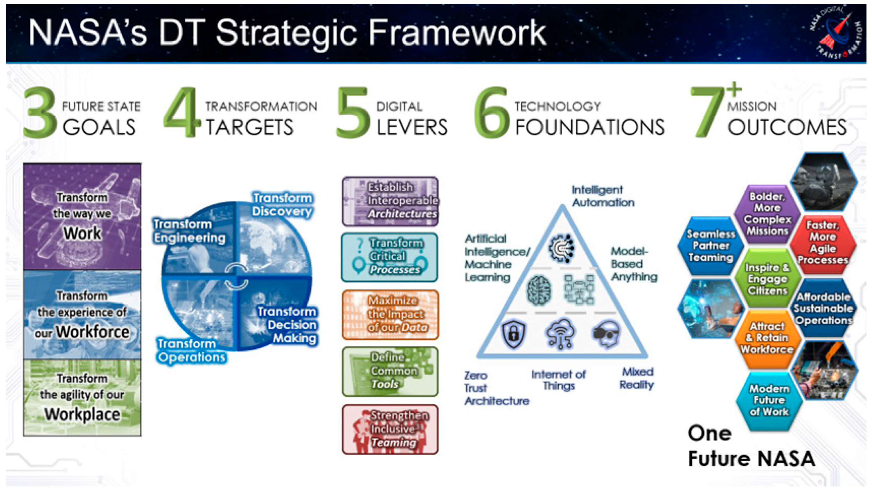
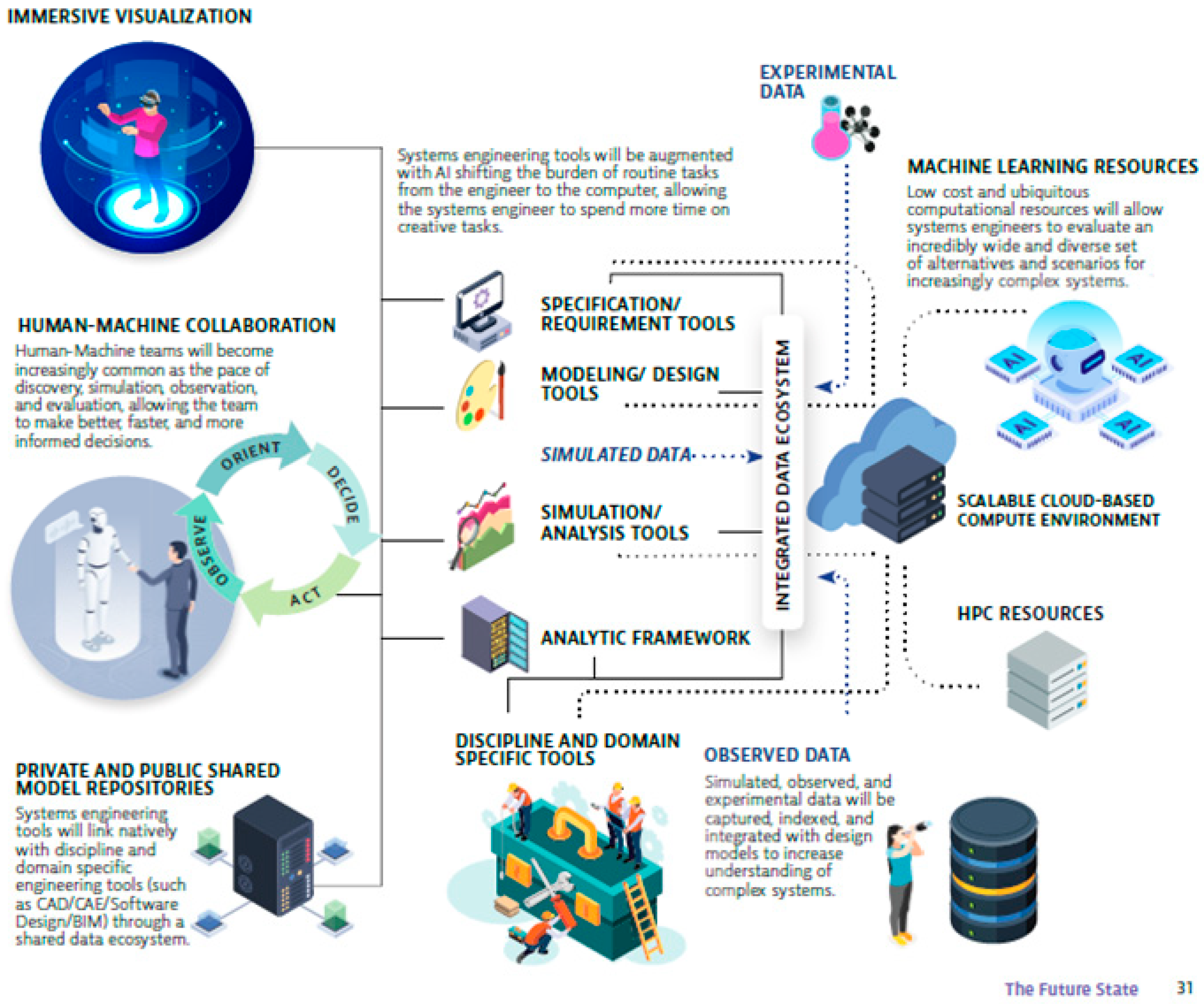
1.2.2. United States National Aeronautics and Space Administration (NASA)

The United States National Aeronautics and Space Administration (NASA) has issued a strategic framework for their digital enterprise that includes three goals; four transformation targets; six digital levers; six technology foundations; and seven mission outcomes [8]. The portion of NASA’s framework that is most pertinent to the subject of this paper is the six (6) technology foundations depicted in Figure 2.

1.2.3. International Council on Systems Engineering (INCOSE)

The International Council on Systems Engineering (INCOSE) is a professional organization founded to develop and disseminate the transdisciplinary principles and practices that enable the realization of successful systems. In their report Systems engineering vision 2035: Engineering solutions for a better world [11], the future state vision projects that “systems engineering environments fully leverage advances in digital technologies and modeling standards to enable rapid exploration of designs using high fidelity simulation, data visualization, and semantic web technologies” [11] (p. 31). Figure 3 is INCOSE’s visualization of the impacts of the digital transformation on systems engineering in the year 2035.
The digital enterprise described in each of the three strategies is supported by unique terminology defined in a digital engineering lexicon that describes the use of digital artifacts in all elements of a system or product life cycle. The next section introduces a digital enterprise lexicon synthesized by the authors from several sources.

1.2.4. Digital Engineering Lexicon

The essential lexicon surrounding the utilization of digital artifacts in the engineering of systems includes:
Artifact: the general understanding of the term artifact in the context of design endeavors is that it is “an object made by humans with the intention that it is used to address a practical problem” [12] (p. 2). In Industry 4.0, artifacts are expected to be digitally contained and will serve as the single authoritative source of system data.
Digital engineering (DE): “An integrated digital approach that uses authoritative sources of systems’ data and models as a continuum across disciplines to support lifecycle activities from concept through disposal” [13] (p. 2).
Digital enterprise: “A term that covers all aspects of the implementation of digital systems in the traditional design process at companies of every scale” [14].
Digital thread: The original notion of the digital thread defined it as “The lifecycle architecture for supporting the development, management, and communication of enduring, authoritative truth sources encompassing all knowledge flows across ideation, design, engineering, manufacturing, testing, operations, and sustainment to inform decision makers through a system’s lifecycle by providing the capability to access, integrate, and transform disparate data into actionable information. The Digital Thread is a feed-forward and feed-back knowledge loop over the system lifecycle” [15] (p. 3). As such, the digital thread is envisioned as “containing all the information necessary to generate and provide updates to a Digital Twin” [16] (p. 4516).
Digital twin: A digital twin is the product of a model-based engineering endeavor and is “a set of virtual information constructs that fully describes a potential or actual physical manufactured product from the micro atomic level to the macro geometrical level. At its optimum, any information that could be obtained from inspecting a physical manufactured product can be obtained from its Digital Twin” [17] (p. 94). Additional information on the history and evolution of the digital twin may be found in [18,19].
Model-centric engineering (MCE): “Model-centric engineering can be characterized as an overarching digital engineering approach that integrates different model types with simulations, surrogates, systems and components at different levels of abstraction and fidelity across disciplines throughout the lifecycle” [20] (p. xiii).
Model-based engineering (MBE): “The model-based engineering (MBE) approach uses these models rather than documents as the data source for all engineering activities throughout the product life cycle. The core MBE tenet is that models are used to drive all aspects of the product lifecycle and that data is created once and reused by all downstream data consumers”. [21] (p. 3).
Model-based systems engineering (MBSE): Model-based systems engineering is a specific technique for conducting model-based engineering (MBE). MBSE is defined as “The formalized application of modeling to support system requirements, architecture, design, analysis, verification and validation activities throughout the life cycle” [22] (p. 101).
Standard: “A document that provides, for common and repeated use, rules, guidelines or characteristics for activities or their results, aimed at the achievement of the optimum degree of order in a given context” [23] (p. 562).

1.3. Summary of Problem Being Addressed

The utilization of digital technologies in Industry 4.0 requires the modification and adaptation of design methodologies to support system design efforts. The utilization of model-based systems engineering (MBSE) within the digital enterprise is necessary to support reproducible, replicable, and generalizability designs for modern cyber–physical systems. The extant literature cited in this paper provides the foundation for understanding how system design efforts may be modified to successfully sustain these systems and their design artifacts through the use of life cycle models and international standards.
The next section will provide an explanation of the foundation life cycle model and international standards for the design of systems for Industry 4.0.

2. Systems in an Industry 4.0 Digital Enterprise

Over time, systems have increased in scale and are characterized by a growing reliance on interoperation to achieve desired outcomes [24]. To address issues associated with increasing system complexity—and the domain pressures caused by competition, time-to-market, and their worldwide adoption and application—traditional third industrial revolution methods and processes utilized to conceive, design, construct, operate, maintain, and dispose of these systems require modification for use in Industry 4.0.
Cyber–physical systems are ubiquitous in Industry 4.0. The term cyber–physical system (CPS) was coined by Helen Gill at the National Science Foundation in the United States in 2006. “CPS is about the intersection, not the union, of the physical and the cyber. It combines engineering models and methods from mechanical, environmental, civil, electrical, biomedical, chemical, aeronautical and industrial engineering with the models and methods of computer science” [25] (p. 4838). Industry 4.0 systems increasingly display all of the characteristics of CPS in the previous paragraph, and are thus referred to hereafter as systems.
The systems supporting Industry 4.0 cannot be developed using techniques and approaches from the third industrial revolution, where engineering systems are conceived in independent stages in one silo, then designed in another silo, and so on. Each time there is a hand-off from one silo or stage to the next, there is potential for loss of momentum and fidelity of the design—or perhaps more severely, the loss or misinterpretation of crucial data and information required to support the evolution of the system design. The Industry 4.0 environment calls for systems to be addressed in toto. An in toto approach requires integration between and among (1) the conception, design, construction, operation, maintenance, replacement, retirement, and disposal stages in what is termed a life cycle; and (2) the subject matter experts and discipline specific tools that support each stage in the life cycle. A life cycle is defined as the “evolution of a system, product, service, project or other human-made entity from conception through retirement” [22] (p. 250).

2.1. International Standards for the Engineering of Systems

To support improved communication and understanding among stakeholders involved with each of the life cycle stages when employing engineering systems, formal systems engineering practices have been developed to define a set of processes that can be used to help establish a technical template for system design endeavors. These practices are contained in a series of international standards. The standards are developed, issued, and maintained by a tripartite of standards organizations: (1) the International Organization for Standardization—ISO; (2) the International Electrotechnical Commission—IEC; and (3) the Institute of Electrical and Electronics Engineers—IEEE. Table 2 is a partial listing of the international standards relevant to the life cycles of systems.

2.2. Life Cycle Models

In order to adequately address the integration of the various specialized engineering practices required throughout the life cycle of a modern system, and to guide the overall life cycle development, a model for the system’s life cycle is utilized. A system life cycle model is defined as the “framework of processes and activities concerned with the life cycle that may be organized into stages, which also acts as a common reference for communication and understanding” [22] (p. 251). Life cycle models typically include a number of unique stages, which are defined as a “period within the life cycle of an entity that relates to the state of its description or realization” [22] (p. 435). The type of life cycle model may vary depending upon the domain for the system-of-interest (SoI), but every life cycle model is a depiction of the flow of stages from conception through retirement and disposal. Life cycle models are differentiated by the number and types of stages and how their flows are represented in the movement from stage-to-stage. Typical life cycle models include waterfall models, spiral models, Vee models, iterative models, etc. [26].

2.3. Life Cycle Process Models

The most important aspect of the life cycle model is that it is serves as the overarching structure or framework that will be utilized to move a system, stage-by-stage, from conception through to, ultimately, retirement and disposal. Each stage in the life cycle model contains formal processes which specify the inputs, outputs, and outcomes necessary for the successful accomplishment of the stage. The addition of the formal processes aid the transition from a life cycle model to a life cycle process model. The life cycle process model describes the specific processes that must be performed to successfully accomplish the stages defined in the life cycle model. The most widely adopted life cycle process model for systems of the third industrial revolution was the Vee model, first proposed by Forsberg in 1991 [27,28]. Figure 4 is a depiction of a generic systems engineering Vee life cycle process model and its associated stages.

2.4. Life Cycle Model for Industry 4.0

The Vee life cycle process model depicted in Figure 4 was adequate for the systems approaches of the third industrial revolution; however, it will not support the approaches needed by the digital enterprise of Industry 4.0. A newer diamond-shaped model was developed to relate the life cycle relationships described in the traditionally used Vee life cycle process model with the concepts introduced in the digital enterprise. This model is the Boeing Diamond©.
The Boeing Corporation has encapsulated the tenets described in the digital enterprise in an advanced life cycle model, termed the Boeing Diamond© [30]. The Boeing Diamond© is a life cycle model that transforms needs into solutions by combining aspects of the third industrial revolution’s Vee life cycle process model represented in Figure 4 with elements from the digital enterprise. The Boeing Diamond© is depicted in Figure 5.
In Figure 5, the design and delivery elements of the physical system are represented by the lower half of the diamond. In the lower Vee, design elements flow down and the delivery elements flow up, resulting in a solution that takes the form of either a product or system. Figure 6 provides the authors’ detailed decomposition of the lower Vee of the Boeing Diamond© using information from the international standard for life cycle processes—ISO/IEC/IEEE Std 15288 [31]. The 15288 standard provides guidance on the processes necessary to facilitate a system life cycle development effort. Because of its wide acceptance across the systems engineering domain, and because of its general applicability to system design efforts, the life cycle processes described in the 15288 are well-suited to represent the processes typically included in a life cycle development effort. The standard is described in more detail in Section 2.5, and it is used as a baseline technical document for the development of the 15288-SysML Grid concept discussed later on in Section 4.
The top half of the diamond represents the virtual system, which is the digital representation of the physical system. The elements of the top half of the diamond include virtual elements from both modeling and simulation endeavors. As the upper Vee ascends, system models are developed that feature increasing levels of technical detail of the system of interest (SoI). As the upper Vee descends, simulations are performed to verify and validate the developed virtual models.
The modeling elements that comprise the model development process for the upper Vee are (1) the system model; (2) sub-system models; (3) component models; and (4) the production model. Each of these models includes additional detail as the design process advances. The simulation elements that comprise the simulation processes for the upper Vee are (5) virtual assembly models; (6) virtual qualification models; (7) virtual certification models; (8) virtual operations models; and (9) virtual support models. Figure 7 depicts the virtual modeling and simulation elements that constitute the upper Vee of the diamond.
The linkage between the upper and lower halves of the diamond relate the physical and the virtual elements, specifically (1) the design and modeling elements; and (2) the delivery and simulation elements. The red and green rectangles in Figure 8 are an example which illustrates three of these linkages. In the depiction, the horizontal linkages in green relate to (1) the relationship between the design and delivery elements for component design and component verification; and (2) the relationship between component models and model certification. Similarly, the vertical linkage in red depicts the relationship between the delivery and simulation elements for component design and component models. All three of the relationship links are enabled by the digital thread where the design, delivery, modeling, and simulation elements are digitized and stored within a common repository.
The interior of the diamond contains a visualization of the digital thread which includes the mechanisms for the creation, storage, and utilization of the digital artifacts that form the data, relationships, perspectives, and views that enable the processes. The digital thread will be discussed further in Section 2.6.

2.5. ISO/IEC/IEEE Life Cycle Processes

The stages within life cycle models are accomplished through the planning and execution of dedicated processes. The international community has specified the processes for the stages of the systems life cycle in the international standards presented earlier in Table 1. Each of the international standards include the processes and an associated hierarchy of activities and tasks that provide the inputs, outputs and outcomes required to successfully accomplish the life cycle processes [32]. The elements of the hierarchy are defined as follows:
Process: “Set of interrelated or interacting activities that transforms inputs into outputs”
[22] (p. 337).
Activity: “set of cohesive tasks of a process”
[22] (p. 9).
Task: “Required, recommended, or permissible action, intended to contribute to the achievement of one or more outcomes of a process”
[22] (p. 460).
The utilization of formal standards-based processes—with their supporting activities and tasks—provides a common approach from which system life cycle stages in any life cycle model may be executed. Using this common standards-based approach directly supports improved communication and understanding amongst stakeholders involved in the system endeavor.
As shown in Table 2, several standards exist that are associated with the life cycle of systems. The ISO/IEC/IEEE Standard 15288 [31] has generally been recognized as the de facto standard used to define the processes generally applicable across system life cycle efforts for various application domains. The 15288 standard for systems comprises four (4) major process areas which are further decomposed into thirty (30) constituent processes. Taken in its entirety, each of the processes in the 15288 standard span the entire life cycle of a system—from conception to retirement and disposal. The major process areas and their respective processes are summarized in Figure 9.
The technical processes (in blue) in Figure 9 are most commonly associated with life cycle process models and can be used as a general outline for system life cycle development efforts. These technical processes are listed sequentially; however, they can be performed iteratively or in a unique sequence, dependent upon the needs of the organization involved with the system. Most importantly, the insights and results from a downstream process may be used to enhance the insights obtained from a previously conducted process, and the process flows may be arranged for iterative, recursive, or concurrent execution.
The 15288 technical processes in the blue box of Figure 9 address the design and delivery (6.4.1 to 6.4.14) elements of the physical system and further refine the concepts initially defined in the lower half of the diamond. Their relationships with other international standards are depicted in Figure 10.
Similarly, the 15288 technical management processes in the yellow box of Figure 9 (6.3.1 to 6.3.8) are interrelated with other standards, as depicted in Figure 11.
Given the 15288 standard’s general applicability, complemented by its international acceptance as a baseline technical document, the guidance provided in the 15288 standard represents a unique opportunity for integration and application to support the concepts encapsulated in digital engineering approaches for engineering systems [33,34,35,36,37]. However, to date, a description of the potential nexus between digital engineering efforts and standards published to support life cycle development have not been addressed.
The section that follows will describe a system life cycle process model that combines the guidance from international standards with the Boeing Diamond© life cycle model to produce a framework for the design of Industry 4.0 systems.

2.6. An Articulated Boeing Diamond© as a Life Cycle Process Model for Industry 4.0

The Boeing Diamond© life cycle model, with the upper Vee, lower Vee, and digital thread are populated with the ISO/IEC/IEEE 15288 technical processes from Figure 9 to create a new articulated diamond-shaped life cycle process model. The addition of the technical processes adds a level of granularity that permits practitioners to execute the design and delivery processes. Figure 12 is a depiction of the diamond-shaped life cycle process model with the relevant 15288 technical processes from Figure 10, integrating the roles played by the management processes from Figure 11 (process highlighted in red).

2.7. The Digital Thread

The concept of the digital thread was introduced in Section 1.2.4 as a key term in the digital engineering lexicon. The digital thread is the source of authoritative truth within the articulated diamond life cycle process model in Figure 12. It provides the digital artifacts that form the relationships, perspectives, and views that enable the 14 technical processes, the 8 technical management; 2 agreement; and 6 organizational enabling processes contained in the 15288 life cycle process standard in Figure 9 (Note: The authors have not addressed (1) the two (2) agreement processes contained in Section 6.1 of 15288 nor (2) the six (6) organizational enabling processes contained in Section 6.2 of 15288, as they have little impact on the technical modeling aspects of the system design process). The digital thread serves to merge all of the engineering discipline-specific models within a central repository where “its ultimate goal is to be the definitive repository of authoritative information containing everything we know about the system at that instant of time” [38] (p. 47). As such, the digital thread is able to address time and accurately represent the SoI as it changes over time. The system model and the physical model use the data as a function of time, where the “Digital Thread then can be viewed as containing all the information necessary to generate and provide updates to a Digital Twin” [16] (p. 4516).
The next major section will focus on the execution of the fourteen (14) 15288 technical processes and how they are utilized to create, utilize, and maintain authoritative system data, within the digital thread, through the use of model-based systems engineering (MBSE) techniques.

3. Model-Based Systems Engineering (MBSE)

Model-based systems engineering (MBSE) is defined as:
“The formalized application of modeling to support system requirements, architecture, design, analysis, verification and validation activities throughout the life cycle”
[22] (p. 101).
MBSE is part of a long-term trend toward model-centric approaches adopted by a number of engineering disciplines. In Systems Engineering Vision 2035: Engineering systems for a better world, INCOSE reports that MBSE is supported by “Descriptive models created using semantically rich modeling standards that provide systems abstraction, data traceability, separation of views, and leverage AI/ML-based (i.e., Artificial Intelligence/Machine Learning) reference model reuse at both systems and product realization levels” [11] (p. 34).
The structure of MBSE and its relationship to a system in (1) physical models, (2) virtual models or a digital twin, as well as (3) modeling tools, analysis tools, and the notional life cycle, are depicted in Figure 13.
“MBSE is an approach to reduce the complexity of working with increasingly complex systems” [39] (p. 305). As such, MBSE’s raison d’être is to support development of digital models that serve as representations of the designs under development at a mutually agreed upon level of granularity. Moreover, the model-based representations are intended to serve as the technical baseline of design-related information for the SoI, and the models can support the delivery and communication of design artifacts that are produced throughout the system life cycle. Before describing the details associated with modeling systems using an MBSE approach, it is worth reviewing the four broad concepts that underly all MBSE applications, which Delligatti [40] has labeled the Pillars of MBSE. These concepts are elements essential for the successful implementation of a model-based approach for systems engineering endeavors.

3.1. Pillar I: Modeling Language

The modeling language defines the elements that are input to the model, and it establishes the semantics and notation used to display elements and relationships on various diagram types that are also defined by the language. While the implementation of MBSE may be realized through a small set of modeling languages, the Object Management Group’s Systems Modeling Language™ (OMG SysML® located at www.omg.org), hereafter referred to as SysML, is the de facto standard and the most prevalent language used for system modeling. SysML is an object-oriented modeling language derived from the Object Management Group’s Unified Modeling Language™ (UML®). Unlike many other modeling languages that have been developed to facilitate MBSE applications, the modeling constructs of SysML are described in the ISO/IEC International Standard 19514 [41]. As such, it is the only open international standard that has the scale and vendor support to tackle the problem of supporting digital systems engineering efforts across a variety of engineering domains.
Nine diagram types are used to represent the system in terms of its behavior, requirements, and structure. The organization of the nine SysML diagram types is shown in Figure 14.
Table 3 is a description of how each of the nine (9) SysML diagram types are utilized in modeling the structure, behavior, and requirements aspects of systems.
Through the utilization of each of the nine SysML diagram types described in Table 3, four fundamental aspects of system design are able to be captured and presented in system models [42]. The fundamental design aspects captured in SysML models are (1) behavior; (2) requirements; (3) structure; and (4) parametric relations. These design aspects represent the system-of-interest (SoI), and the SoI’s hierarchical structure of sub-systems, and components with the nine (9) diagram types. The diagram types are able to include the fidelity necessary to establish and integrate the information contained within and between each diagram. For example:
  • Behavior: Behavioral aspects (i.e., how it responds to its environment) of a system, including states and transitions, that can be integrated with the respective components in the SoI that enable its behavior.
  • Requirements: Requirement aspects represent the specification of a capability or condition that a system must satisfy. Requirements are hierarchical and initially specified at the system level. The system-level requirements are further refined and allocated to the sub-systems and components. SysML diagrams support the ability to specify, derive, satisfy, verify, refine, trace, and relate requirements throughout the model, which enables the clear definition of requirements and their relation to the system throughout each of the stages of the life cycle.
  • Structure: The structural aspects are based upon a central principle of systems engineering: hierarchy [43]. Nobel Laureate Herbert Simon [1916–2001] stated “By a ‘hierarchic system,’ or hierarchy, I mean a system that is composed of interrelated subsystems, each of the latter being, in turn, hierarchic in structure until we reach some lowest level of elementary subsystem” [44] (p. 68). Hierarchy in design is typically implemented through decomposition, where the overall concept for a design can be formulated at a high level and decomposed into system, subsystem, and lower-level components, all the way down to unique parts. In addition, structure describes interconnections and interfaces between systems, subsystems, and components.
  • Parametric Relations: Parametric relationships constrain the system design to certain values or parameters that can be allocated to the appropriate behavioral or structural feature of the design that has been specified in a SysML diagram. As such, the parametric aspect supports establishment of constraints and mathematical statements.
The four fundamental aspects of system design, captured with SysML diagrams, are used to create a single unified model of the system that can represent all of its varied aspects and their inter-relations.

3.2. Pillar II: Modeling Method

Since modeling languages only specify the elements that can be used to develop system models, a modeling method is necessary to dictate how the elements should be used to develop coherent system models. Modeling methods are largely user-driven and can vary depending on the desired outcome of the modeling effort. In the context of MBSE, several modeling methods have been developed, spanning several modeling languages and application domains [45,46]. A brief summary of the prominent modeling methods are summarized in Table 4.

3.3. Pillar III: Modeling Tool

The modeling tool enables Pillars I and II (the modeling language and the modeling method) to be realized in a digital environment. The chosen environment and enabling tools (i.e., Dassault Systemes’ Cameo systems modeler; IBM’s Telelogic Harmony, Rational, and Rhapsody, etc.) are often driven by user preference, but may be specified by stakeholders. The modeling tool can also feature packages or libraries—unique to the specific environment—which enable specialized applications of modeling to be applied (e.g., model simulation or safety and reliability analysis). Regardless of the environment chosen, each modeling tool is designed to comply with the rules, semantics, and notations established in the embedded language (i.e., SysML, LML, etc.).

3.4. Pillar IV: Organizational Support

In addition to Delligatti’s three established pillars [40], there is a proposed fourth pillar that addresses the organization that adopts an MBSE approach [69]. A common misunderstanding in the engineering community is that the modeling language itself is enough to successfully apply MBSE within an organization. However, life cycle models, combined with formalized guidance from standards, such as the 15288 standard, must be included as a framework for MBSE to be useful in supporting system endeavors [70]. To realize the successful implementation of MBSE, there are a number of organizational challenges that must be overcome that have little to do with either the model-based (MB) or the systems engineering (SE) elements of MBSE. These challenges include executive-level sponsorship, awareness, and resistance to change [69]. To that end, the proposed fourth pillar emphasizes the importance of the organizational and cultural acceptance of the practice of MBSE, which is oftentimes characterized by a paradigm shift away from a document-centric approach to system development and onwards to a model-centric approach.
In summary, the system model created through the application of MBSE not only captures vital aspects of the system design, but also acts as a centralized repository that can integrate digital design artifacts from the various technical disciplines featured throughout the system life cycle. These design artifacts can serve as elements that are input to the model, and the resulting information—now contained in the system model—can supply important design-related information to other discipline specific models. In doing so, a single source of relevant data for the production of information in support of model-wide analyses and simulations is supported.
The next section describes the creation of a grid concept that relates the four fundamental aspects of design captured in system models with the 15288 standard’s technical processes.

4. Engineering Systems Using the 15288-SysML Grid

Although the articulated diamond life cycle process model, shown in Figure 12, serves as an initial outline for the integration of the technical processes described in the 15288 standard and the digital enterprise, the realization of such an approach has not yet been achieved. MBSE approaches—facilitated using SysML—have the potential to bridge the gap between the digital enterprise and the processes outlined in the 15288 standard. However, a direct correlation between the modeling elements in SysML (i.e., the diagram types described in Section 3.1) and the relevant processes from the 15288 standard must first be established. To that end, the 15288-SysML Grid framework was conceptualized by the authors to correlate guidance from the 15288 standard with SysML. The creation of such a framework directly supports the concepts described in the articulated diamond life cycle process model by providing a template for the realization of each of the life cycle stages in a self-contained system model—which is consistent with the principles of the digital enterprise and Industry 4.0. This section will further describe the Grid framework and how it can be used to guide a SysML model development approach that is consistent with the technical processes described in the 15288 standard.

4.1. Foundation for the 15288-SysML Grid

The foundation for the creation of the 15288-SysML Grid is based upon the following supporting elements:
  • Paradigm: Industry 4.0, described in Section 1.1, is the moniker for the fourth industrial revolution and the current paradigm shift toward the creation and utilization of digital data in real-world objects. The real-world objects possess digital data and resultant information, embedded in modern systems.
  • Digital Enterprise: Industry, government, and professional organizations have conceptualized strategies to support the objectives of Industry 4.0. The digital enterprises, described in Section 1.2, provide strategies and a vision for implementation of a digital environment for Industry 4.0’s modern systems. Section 1.3 provides a lexicon of terminology for the digital enterprise.
  • Articulated Diamond Life Cycle Process Model: The Boeing Diamond© life cycle model is adapted and transitioned to a life cycle process model that includes: (1) design and delivery elements for the physical system; (2) modeling and simulation elements for the virtual system; (3) a digital thread, which contains the mechanisms for the creation, storage, and utilization of the digital artifacts that are the source of the data, relationships, perspectives, and views; and (4) the formal life cycle processes contained in international standards.
  • ISO/IEC/IEEE Standards: The international standards in Table 2 contain the formal systems engineering processes needed to address all aspects of the systems life cycle.
  • Four Fundamental Design Aspects: The four fundamental aspects of system design captured through system models are (1) behavior; (2) requirements; (3) structure; and (4) parametric relationships. These aspects enable the modeling of the system-of-interest (SoI), the SoI’s sub-systems, and components within structured diagram types.

4.2. Methodolgy for 15288-SysML Grid Development

Building upon an approach first conceptualized by Mazeika, et al. [71] and Morkevicius, et al. [72], the articulated diamond life cycle process model and four fundamental aspects of system design in SysML are aligned in a grid labeled the 15288-SysML Grid.
The design and delivery elements, depicted in the articulated diamond life cycle process model in Figure 12, may be represented at any level (i.e., process, activity, task, outputs, outcomes) contained in the 15288 processes on the vertical axis. The four fundamental aspects of system design serve as the horizontal axis.
The utilization of the Grid, in conjunction with a formal life cycle model and international standards, is intended to have a positive impact on the system design process. Specifically, reproducibility, replicability, and generalization, as herein defined:
Reproducibility: In this sense we are addressing computational reproducibility where the design process is “obtaining consistent computational results using the same input data, computational steps, methods, and code, and conditions of analysis“ [73] (p. 1).
Replicability: “Obtaining consistent results across studies aimed at answering the same scientific question, each of which has obtained its own data” [73] (p. 1).
Generalizability: “Refers to the extent that results of a study apply in other contexts or populations that differ from the original one” [73] (p. 1).
All three elements, reproducibility, replicability, and generalizability, are intended to be improved through use of the 15288-SysML Grid. This is accomplished through a repeatable process from the ISO/IEC/IEEE Standard 15288 and the use of the SysML modeling language. The combination of the two axes result in a Zachman [74,75] type grid where the resultant inner cells reveal the relevant SysML diagram types that may be utilized to support the realization of the process outcome. Table 5 is the notional 15288-SysML Grid for technical processes.
Conceptually, a similar grid may be also constructed for the other three 15288 standard process areas: (1) an agreement process area with two processes; (2) an organizational process-enabling area with six processes; and (3) a technical management process area with eight processes. However, because the technical processes are most commonly associated with life cycle design and delivery elements, they were prioritized for the 15288-SysML Grid framework.
Nine SysML diagram types may appear within 15288-SysML Grid. The diagram types and their abbreviations are those listed in Table 3. Using the four fundamental design aspects of SysML as the organizational construct, certain diagram types are able to be appropriately used to satisfy the outcome described in the 15288 standard. Specifically, the design aspects can be captured using one or more of the nine prescribed SysML diagram types from Table 3. The approach taken to relate the outcomes defined in the 15288 technical process was to evaluate the outcome, and its supporting activities and tasks, and determine what fundamental design aspect the outcome is intended to address. Once this determination is made, the potential diagram types are narrowed down to those that are able to accurately capture the design aspect. This taxonomy was initially conceptualized in the SysML diagram hierarchy depicted in Figure 14. However, the concept is further refined to support the Grid development as follows:
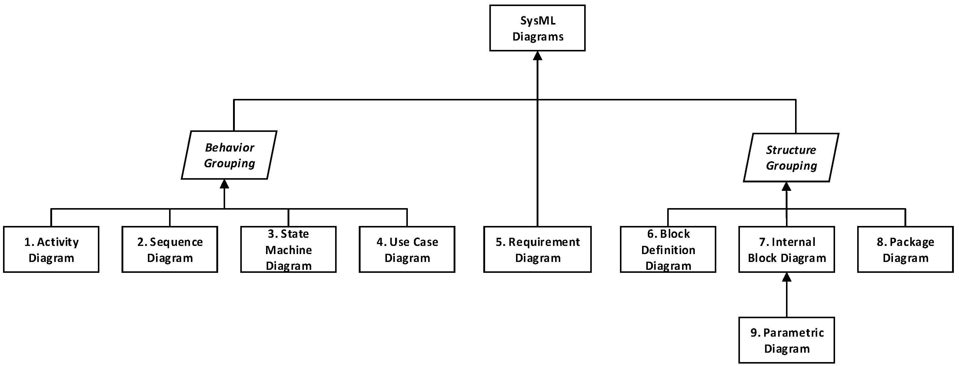
  • Behavior-related design aspects are captured in SysML using the uc, act, stm, and seq diagram types.
  • Requirement-related design aspects are captured using the req diagram type.
  • Structural-related design aspects are captured using the pkg, bdd, and ibd diagram types.
  • Parametric relations are captured using the par diagram type.
Using this taxonomy, and the design aspect being addressed by the 15288 outcome, a preliminary determination of the appropriate diagram type (or types) that can be used to satisfy the outlined guidance is made. The determinations of the appropriate realizing diagram (or diagrams) used to capture the 15288 outcome were made by analyzing the content of the outcome and using the formal definitions of the relevant diagram types from Table 3, and the author’s experience applying SysML to complex systems design [76,77]. Specifically, the natural language of each of the outcomes was assessed and, based on the description, the fundamental design aspect being addressed by the outcome was assigned.
For those outcomes that pertain to establishing the system users or potential stakeholders associated with the system, the fundamental design aspect being addressed is categorized as being behavior-related and uc diagrams can be used to support the outcome realization. For those outcomes that specify the definition of operational concepts or the establishment of system behavior (either in terms of inputs and outputs, temporally driven sequences, or explicit system states), act, seq, and stm diagrams can be used to support the outcome realization. The selection of the appropriate diagram type is ultimately dictated by the specified outcome, and, depending on the outcome specification, the use of multiple behavior-related diagrams may be necessary to fully address the process step.
Outcomes that are requirement-related are addressed using req diagrams. These diagram types are used to refine stakeholder needs and capabilities into defined system requirements which can then be traced and allocated to realizing the system features modeled using other diagram types. Depending on the requirement-related process specification described in the outcome, certain features of the requirements diagram will need to be used. Guidance on the use of which modeling features of a given diagram type are out of the scope of the current development effort; however, the general constructs available using the req diagram can be used by the practitioner to satisfy the specified process outcome using the desired methodology listed in Table 4.
Structural-related outcomes are those outcomes that either specify the need to establish the system context (i.e., to support the definition of system boundaries, interfaces, subsystems, components or enabling systems). The pkg diagram is used to organize the contents of the model and is used to support outcomes that involve the identification of multiple system elements—such as relevant stakeholders—and enabling systems required for the realization of the outcome. The use of pkg diagrams for these specific outcome types provides an initial outline for the structure of the model, as they can be used to access other portions of the system model. With respect to outcomes that explicitly require the definition of system features such as interfaces or boundaries, bdds and ibds are used to represent high-level system depictions and the associated internal structure of the high-level depictions. Blocks within bdds are used to define relevant design features included in the system, as well as the inherent properties associated with them. Furthermore, bdds are able to formally define structural hierarchies (such as system–subsystem–component relationships) found within the system. When outcomes specify the need for additional detail for a potential solution system, bdds alone may not be sufficient. In this case, ibds are used to supplement the higher-level bdds by providing internal models of the blocks in terms of their properties and interconnections.
The final outcome types specified in the 15288 standard are those that describe parametric relationships. In the context of SysML model development, these relationships define measurable parameters that are used to assess the system design’s ability to satisfy defined requirements. Additionally, they are used to formalize design constraints imposed on the system. Regardless of the type of parametric relationship used to support the outcome, the SysML diagram type that must be used is the par diagram. Therefore, any process outcome that specifies the establishment of system constraints or performance measures will be supported using par diagrams.
Using the conceptual mapping of the 15288 process outcome to the appropriate SysML diagram type, the 15288-SysML Grid enables practitioners to understand the relationship of a particular standards-based process with a particular SysML diagram. Specifically, the Grid provides the type of information that can be included in the model to satisfy the 15288 process outcome (depicted in the Grid using non-italicized text) and the SysML diagram type that can be used to capture the information from the process outcome (depicted in italics using the diagram abbreviations defined in Table 3). The SysML diagram may be used to capture the relevant data and information from the inputs, outputs, and outcomes of the respective technical process. There are, however, several considerations to account for in the present iteration of the 15288-SysML Grid. Foremost, due to the conceptual nature of the framework, several assumptions were made in relating the 15288 process outcomes to the appropriate realizing SysML diagram type(s). For example, it is assumed that the diagram types mentioned are sufficient to satisfy the outcome. However, in practice, the use of additional diagram types may be necessary to fully realize the outcome of the process. The current determinations of the SysML diagram types were made based on the design aspect being addressed by the outcome and the formal definition of the SysML diagram types. Additionally, previous modeling experience by the authors was used to supplement the determination when needed. The criteria that were used to make the appropriate diagram determinations were based on a combination of the natural language of the outcome description, the formal definition of the SysML diagrams, and previous modeling experience. Another consideration to note for the application of the 15288-SysML Grid approach is the level of familiarity with SysML. It is assumed that a potential user of the developed approach is familiar with the concepts of SysML and the associated diagrams used to support model development efforts. However, if a potential practitioner is not versed in SysML model development, time would need to be dedicated to gain familiarity with the language so that the approach may be properly utilized. Other potential considerations for the application of the Grid approach include an organizational buy-in for the use of MBSE (see Section 3.4) and the integration of the 15288 processes with existing design practices.
The next section provides two examples of how the Grid may be utilized with 15288 technical processes.

4.3. Example 1: Implementing 15288-SysML Grid for Technical Process 6.4.2

The defined purpose of the stakeholder needs and requirements definition process (15288 process 6.4.2) is to “define the stakeholder requirements for a system that can provide the capabilities needed by users and other stakeholders in a defined environment. It identifies stakeholders, or stakeholder classes, involved with the system throughout its life cycle, and their needs. It analyzes and transforms these needs into a common set of stakeholder requirements that express the intended interaction the system will have with its operational environment and that are the reference against which each resulting operational capability is validated. The stakeholder requirements are defined considering the context of the system-of-interest with the interoperating systems and enabling systems” [31] (p. 62). There are nine (9) outcomes for the process. Each of the outcomes may be accomplished through the use of one or more SysML diagrams. The 15288-SysML Grid serves as a guide for the practitioner using MBSE with SysML; specifically, the selection of appropriate SysML diagram types during the design process.
An analysis of the stakeholder needs and requirements definition outcomes in the 15288 standard revealed that, oftentimes, multiple aspects of design may be addressed. When this is the case, the relevant diagram types corresponding to the design aspects associated with the outcome guidance may also be included in the Grid. For example, outcome 3 of the stakeholder needs and requirements definition process necessitates that constraints on a system are defined. Constraints on a system are formalized in SysML using par diagrams to establish constraints on properties associated with blocks. The use of par diagrams, then, necessarily involve the development of bdds that define blocks with the properties that must be constrained. Additionally, the constraint on the system is formally defined using requirements established using a req diagram. The foregoing analysis points to a total of three design aspects that must be considered to satisfy the overall outcome. The three corresponding diagram types that are then required to support the realization of the outcome in SysML are the req, bdd, and par diagrams. The results from this process are included in Table 6, which represents the 15288-SysML Grid addressing the stakeholder needs and requirements definition process (15288 process 6.4.2).
A practitioner can use the 15288-SysML Grid depicted in Table 6 to identify the process outcome of interest, verify the design aspect, and then select the appropriate SysML diagram indicated in the Grid. Following this approach supports an MBSE approach to system life cycle development while also adhering to the technical processes outlined in the 15288 standard.

4.4. Example 2: Implementing the 15288-SysML for Technical Process 6.4.3

The defined purpose of the system requirements definition process (15288 process 6.4.3) is to “transform the stakeholder, user-oriented view of desired capabilities into a technical view of a solution that meets the operational needs of the user. This process creates a set of measurable system requirements that specify, from the supplier’s perspective, what characteristics, attributes, and functional and performance requirements the system is to possess, in order to satisfy stakeholder requirements. As far as constraints permit, the requirements should not imply any specific implementation”. [31] (p. 66). There are six (6) outcomes for the process. Each of the outcomes may be accomplished through the use of one or more SysML diagrams. Using the same process described in the previous example, the appropriate SysML diagram type (or types) is allocated to the outcome described in the 15288 standard. The results of this process, captured in Table 7, can serve as a guide for a potential MBSE practitioner performing the systems requirements definition process outlined in the 15288 standard.

5. Recommendations for Future Research

The authors’ future research direction for this work includes the development of the 15288-SysML Grid concept for each of the 15288 life cycle processes and the creation of a companion 15288 SysML metamodel—similar to the metamodel in use by NASA [78,79]. This research would formalize the associations described in the 15288-SysML Grid as a distinct MBSE methodology. Conceptually, this research path would include a methodology that includes items such as a user manual, template for each 15288 process, and associated workflow. At the conclusion of this research the articulated diamond life cycle model completed with all of the elements of the 15288-SysML Grid may be considered to be a foundation for the 15288-SysML toolbox.
In addition, future research should explore, validate and build on the framework using other cases, with emphasis on different industry sectors, application domains, and system types. Investigation within these expanded areas may be used to validate and improve the 15288-SysML Grid through case studies, industry applications, or empirical research.
Finally, future research could include engaging with organizations that have recently started to implement MBSE and doing pilot projects as a source for the generation and of empirical data and information on the validity of the proposed framework

6. Conclusions

The 15288-SysML Grid described in this article supports Industry 4.0 and its supporting digital enterprise through application of a modern life cycle process model in the adapted diamond, the utilization of international standards for systems, and the four fundamental aspects of system design supported by MBSE and SysML. The impacts and outcomes of the 15288-SysML Grid on the system engineering practice, and both its potential benefits and drawbacks, are worthy of consideration.
The benefits and obstacles to the utilization of the 15288-SysML Grid mirror those reported for the implementation of MBSE [80]. The most important benefits are multidisciplinary participation through the inclusion of all relevant stakeholders and the ability to improve reproducibility, replicability, and generalizability of system designs. Obstacles include a quantifiable benefit to implementing organizations and the needs to develop expertise in both MBSE and the SysML language.
Despite the identified obstacles, the authors believe that the development of the 15288-SysML Grid provides systems practitioners and those responsible for the life cycle design of Industry 4.0 systems with an improved perspective of the digital enterprise. The integration of all elements of the digital enterprise provides improved communication and understanding for Industry 4.0 systems. The authors’ experience with the design of nuclear power plant systems [76,77] improved the design process by (1) avoiding the delays caused by handoffs between silos and stages most often encountered with the traditional approaches associated with the third industrial revolution; and (2) improving the reproducibility of a previous design [77].
A specific benefit provided by the 15288-SysML Grid is the intersection of the processes contained in the ISO/IEC/IEEE life cycle standards with the four fundamental design aspects captured by SysML during a MBSE design approach. The intersection within the 15288-SysML Grid allows for the creation, storage, and utilization of digital artifacts to form the data, relationships, perspectives, and views that enable the 14 technical, 2 agreement, 6 organizational-enabling, and 8 technical management processes contained in the 15288 standard. In describing the implementation of the 15288-SysML Grid, the authors have used terms such as necessary and sufficient to address expectations for attributes like granularity and elucidate the level of detail of the system. Such qualitative descriptors are fully consistent with the early conceptualization of 15288-SysML Grid; in addition, it brought to mind, for one author, the six year evolution of the safety standard system of the U.S. Department of Energy as it transitioned from an expert-based safety system to one based on national and international consensus standards; they described the resultant set of standards as both necessary and sufficient [81].

Author Contributions

Conceptualization, K.M.A. and S.K.; methodology, K.M.A. and I.I.; writing—original draft preparation, K.M.A. and I.I.; writing—review and editing, S.K. All authors have read and agreed to the published version of the manuscript.

Funding

Irfan Ibrahim’s work was supported under Cooperative Agreement DE-NE0009086 awarded by the US Department of Energy Office of Nuclear Energy (DOE-NE) Nuclear Energy University Program (NEUP) Fellowship and Scholarship support program.

Data Availability Statement

Data are contained within the article.

Conflicts of Interest

The authors declare no conflicts of interest.

References

  1. Schwab, K. The Fourth Industrial Revolution; Crown Publishing: New York, NY, USA, 2016. [Google Scholar]
  2. Kuhn, T.S. The Structure of Scientific Revolutions, 3rd ed.; University of Chicago Press: Chicago, IL, USA, 1996. [Google Scholar]
  3. NIST. Framework for Cyber-Physical Systems: Volume 1, Overview; National Institutes of Standards and Technology: Gaithersburg, MD, USA, 2017. [Google Scholar]
  4. Gibson, I.; Rosen, D.; Stucker, B.; Khorasani, M. Additive Manufacturing Technologies, 3rd ed.; Springer: Cham, Switzerland, 2021. [Google Scholar]
  5. Dutton, W.H. Putting things to work: Social and policy challenges for the internet of things. Information 2014, 16, 1–21. [Google Scholar] [CrossRef]
  6. Liao, Y.; Deschamps, F.; Loures, E.d.F.R.; Ramos, L.F.P. Past, present and future of Industry 4.0—A systematic literature review and research agenda proposal. Int. J. Prod. Res. 2017, 55, 3609–3629. [Google Scholar] [CrossRef]
  7. DoD. Digital Engineering Strategy; Department of Defense: Washington, DC, USA, 2018. [Google Scholar]
  8. Marlowe, J.M.; Haymes, C.L.; Murphy, P.L. NASA Enterprise Digital Transformation Initiative Strategic Framework & Implementation Approach; National Aeronautics and Space Administration: Washington, DC, USA, 2022. [Google Scholar]
  9. INCOSE. Systems Engineering Vision 2025: A World in Motion; International Council on Systems Engineering: San Deigo, CA, USA, 2014. [Google Scholar]
  10. DoD. Digital Engineering; Department of Defense: Washington, DC, USA, 2023. [Google Scholar]
  11. INCOSE. Systems Engineering Vision 2035: Engineering Solutions for a Better World; International Council on Systems Engineering: San Diego, CA, USA, 2021. [Google Scholar]
  12. Weigand, H.; Johannesson, P.; Andersson, B. An artifact ontology for design science research. Data Knowl. Eng. 2021, 133, 101878. [Google Scholar] [CrossRef]
  13. DAU. DAU Glossary of Defense Acquisition Acronyms and Terms; Defense Acquisition University (DAU): Fort Belvoir, VA, USA, 2021. [Google Scholar]
  14. Kargin, Y.O.; Barnes, A.A.; Uysal, O.D.; Pinon-Fischer, O.J.; Balchanos, M.G.; Mavris, D.N.; Hughes, M.; LaJeunesse, J.; Karl, A.; Matlik, J.F. Digital enterprise across the lifecycle. In Proceedings of the AIAA Scitech 2021 Forum (AIAA 2021-0240), Virtual, 19–21 January 2021; pp. 1–22. [Google Scholar] [CrossRef]
  15. Kraft, E.M. Decision analytics in a lifecycle digital engineering environment. In Proceedings of the AIAA Scitech 2019 Forum (AIAA 2019-1364), San Diego, CA, USA, 7–11 January 2019; pp. 1–24. [Google Scholar] [CrossRef]
  16. Singh, V.; Willcox, K.E. Engineering design with digital thread. AIAA J. 2018, 56, 4515–4528. [Google Scholar] [CrossRef]
  17. Grieves, M.; Vickers, J. Digital twin: Mitigating unpredictable, undesirable emergent behavior in complex systems. In Transdisciplinary Perspectives on Complex Systems: New Findings and Approaches; Kahlen, F.-J., Flumerfelt, S., Alves, A., Eds.; Springer: Cham, Switzerland, 2016; pp. 85–113. [Google Scholar]
  18. Zhou, J.; Zhang, S.; Gu, M. Revisiting digital twins: Origins, fundamentals, and practices. Front. Eng. Manag. 2022, 9, 668–676. [Google Scholar] [CrossRef]
  19. Singh, M.; Fuenmayor, E.; Hinchy, E.P.; Qiao, Y.; Murray, N.; Devine, D. Digital twin: Origin to future. Appl. Syst. Innov. 2021, 4, 36. [Google Scholar] [CrossRef]
  20. Blackburn, M. Transforming Systems Engineering through Model-Centric Engineering; Systems Engineering Research Center: Hoboken, NJ, USA, 2018. [Google Scholar]
  21. Lubell, J.; Chen, K.; Horst, J.; Frechette, S.; Huang, P. Model Based Enterprise/Technical Data Package Summit Report; National Institute of Standards and Technology: Gaithersburg, MD, USA, 2012. [Google Scholar]
  22. ISO/IEC/IEEE 24765:2010(E); ISO/IEC/IEEE. International Standard ISO/IEC/IEEE 24765: Systems and Software Engineering—Vocabulary. IEEE: New York, NY, USA, 2017. [CrossRef]
  23. PMI. A Guide to the Project Management Body of Knowledge (PMBOK® Guide), 5th ed.; Project Management Institute: Newtown Square, PA, USA, 2013. [Google Scholar]
  24. Sjarov, M.; Kißkalt, D.; Lechler, T.; Selmaier, A.; Franke, J. Towards “design for interoperability” in the context of systems engineering. Procedia CIRP 2021, 96, 145–150. [Google Scholar] [CrossRef]
  25. Lee, E.A. The past, present and future of cyber-physical systems: A focus on models. Sensors 2015, 15, 4837–4869. [Google Scholar] [CrossRef] [PubMed]
  26. Wynn, D.C.; Clarkson, P.J. Process models in design and development. Res. Eng. Des. 2018, 29, 161–202. [Google Scholar] [CrossRef]
  27. Forsberg, K.; Mooz, H. The relationship of system engineering to the project cycle. In Proceedings of the Joint Conference Sponsored by the National Council on Systems Engineering (NCOSE) and the American Society for Engineering Management (ASEM), Chattanooga, TN, USA, 20–23 October 1991. [Google Scholar]
  28. Forsberg, K.; Mooz, H. The relationship of system engineering to the project cycle. INCOSE Int. Symp. 1991, 1, 57–65. [Google Scholar] [CrossRef]
  29. Forsberg, K.; Mooz, H.; Cotterman, H. Visualizing Project Management: Models and Frameworks for Mastering Complex Systems, 3rd ed.; John Wiley & Sons: New York, NY, USA, 2005. [Google Scholar]
  30. Hatakeyama, S.J.; Seal, D.; Farr, D.; Haase, S.C. Systems engineering “V” in a model-based engineering environment: Is it still relevant? In Proceedings of the 2018 AIAA SPACE and Astronautics Forum and Exposition (AIAA 2018-5326), Orlando, FL, USA, 17–19 September 2018; pp. 1–7. [Google Scholar] [CrossRef]
  31. ISO/IEC/IEEE 15288; ISO/IEC/IEEE. International Standard ISO/IEC/IEEE 15288: Systems and Software Engineering—System Life Cycle Processes. IEEE: New York, NY, USA, 2023. [CrossRef]
  32. Sales, D.C.; Becker, L.B. Systematic literature review of system engineering design methods. In Proceedings of the 2018 VIII Brazilian Symposium on Computing Systems Engineering (SBESC), Salvador, Brazil, 5–8 November 2018; pp. 213–218. [Google Scholar] [CrossRef]
  33. Blackburn, M. Transforming Systems Engineering through Model-Centric Engineering; Stevens Institute of Technology, Systems Engineering Research Center: Hoboken, NJ, USA, 2017. [Google Scholar]
  34. EPRI. Digital Engineering Guide: Decision Making Using Systems Engineering; Electric Power Research Institute (EPRI): Palo Alto, CA, USA, 2021. [Google Scholar]
  35. Weiland, K.J. Future Model-Based Systems Engineering Vision and Strategy Bridge for NASA.; National Aeronautics and Space Administration, Glenn Research Center: Cleveland, OH, USA, 2021. [Google Scholar]
  36. Assef, P.; Geiger, J. Adoption of model-based systems engineering in traditional DoD systems. Def. Acquis. Res. J. 2023, 30, 46–73. [Google Scholar] [CrossRef]
  37. Duprez, J.; Paper, P.; Fraj, A.; Royer, L.; Petteys, B. An approach to integrated digital requirements engineering. In Proceedings of the 33rd Annual INCOSE International Symposium, Honolulu, HI, USA, 15–20 July 2023; Volume 33, pp. 133–149. [Google Scholar] [CrossRef]
  38. West, T.D.; Pyster, A. Untangling the digital thread: The challenge and promise of model-based engineering in defense acquisition. Insight 2015, 18, 45–55. [Google Scholar] [CrossRef]
  39. Holland, O.T. Model-based systems engineering. In Modeling and Simulation in the Systems Engineering Life Cycle: Core Concepts and Accompanying Lectures; Loper, M.L., Ed.; Springer: London, UK, 2015; pp. 299–306. [Google Scholar]
  40. Delligatti, L. SysML Distilled: A Brief Guide to the Systems Modeling Language; Addison-Wesley Professional: Upper Saddle River, NJ, USA, 2013. [Google Scholar]
  41. ISO/IEC. International Standard ISO/IEC 19514 Information Technology—Object Management Group Systems Modeling Language (OMG SysML). 2017. Available online: https://www.iso.org/standard/65231.html (accessed on 27 July 2024).
  42. Friedenthal, S.; Moore, A.; Steiner, R. A Practical Guide to SysML: The Systems Modeling Language, 3rd ed.; Elsevier: Waltham, MA, USA, 2014. [Google Scholar]
  43. Adams, K.M.; Hester, P.T.; Bradley, J.M.; Meyers, T.J.; Keating, C.B. Systems theory: The foundation for understanding systems. Syst. Eng. 2014, 17, 112–123. [Google Scholar] [CrossRef]
  44. Simon, H.A. The architecture of complexity. Proc. Am. Philos. Soc. 1962, 106, 467–482. [Google Scholar]
  45. Estefan, J.A. Survey of Candidate Model-Based Engineering (MBSE) Methodologies, Revision B.; INCOSE: San Deigo, CA, USA, 2008. [Google Scholar]
  46. Estefan, J.A.; Weilkiens, T. MBSE methodologies. In Handbook of Model-Based Systems Engineering; Madni, A.M., Augustine, N., Sievers, M., Eds.; Springer: Cham, Switzerland, 2023; pp. 47–85. [Google Scholar]
  47. Wang, H.; Li, H.; Tang, C.; Zhang, X.; Wen, X. Unified design approach for systems engineering by integrating model-based systems design with axiomatic design. Syst. Eng. 2020, 23, 49–64. [Google Scholar] [CrossRef]
  48. Friedenthal, S.; Oster, C. Architecting Spacecraft with SysML: A Model-Based Systems Engineering Approach; CreateSpace Independent Publishing: Scotts Valley, CA, USA, 2017. [Google Scholar]
  49. Rational. Rational Unified Process for Systems Engineering (RUP SE 1.0); Rational Software Corporation: Cupertino, CA, USA, 2001. [Google Scholar]
  50. Hoffmann, H.-P. System Engineering Best Practices with the Rational Solution for Systems and Software Engineering Deskbook, Release 4.1; IBM Corporation: Somers, NY, USA, 2011. [Google Scholar]
  51. Douglass, B.P. Harmony a MBSE Deskbook Version 1.0: Agile Model-Based Systems Engineering Best Practices with IBM Rhapsody; IBM Corporation: Somers, NY, USA, 2017. [Google Scholar]
  52. Douglass, B.P. Agile Model-Based Systems Engineering Cookbook: Improve System Development by Applying Proven Recipes for Effective Agile Systems Engineering; Packt: Birmingham, UK, 2021. [Google Scholar]
  53. Dori, D. Model-Based Systems Engineering with OPM and SysML.; Springer: New York, NY, USA, 2016. [Google Scholar]
  54. Soffer, A.; Dori, D. Model-based requirements engineering framework for systems life-cycle support. In Managing Requirements Knowledge; Maalej, W., Thurimella, A.K., Eds.; Springer: Berlin/Heidelberg, Germany, 2013; pp. 291–311. [Google Scholar]
  55. ISO/PAS. International Standard ISO 19450: Automation Systems and Integration—Object-Process Methodology. 2015. Available online: https://www.iso.org/standard/62274.html (accessed on 27 July 2024).
  56. Dori, D. Model-based standards authoring: ISO 15288 as a case in point. Syst. Eng. 2024, 27, 302–314. [Google Scholar] [CrossRef]
  57. ISO. International Standard ISO 19450: Automation Systems and Integration—Object-Process Methodology. 2022. Available online: https://www.iso.org/standard/84612.html (accessed on 27 July 2024).
  58. Moore, B.; Dean, D.; Gerber, A.; Wagenknecht, G.; Vanderheyden, P. Eclipse Development Using the Graphical Editing Framework and the Eclipse Modeling Framework; IBM Corporation: Armonk, NY, USA, 2004. [Google Scholar]
  59. Voirin, J.-L. Model-Based System and Architecture Engineering with the Arcadia Method; ISTE Press: London, UK; Elsevier: Oxford, UK, 2018. [Google Scholar]
  60. Voirin, J.-L. Method & tools for constrained system architecting. INCOSE Int. Symp. 2008, 18, 981–995. [Google Scholar] [CrossRef]
  61. Di Maio, M.; Weilkiens, T.; Hussein, O.; Aboushama, M.; Javid, I.; Beyerlein, S.; Grötsch, M. Evaluating MBSE methodologies using the FEMMP framework. In Proceedings of the 7th IEEE International Symposium on Systems Engineering (ISSE 2021), Vienna, Austria, 13 September–13 October 2021; pp. 53–60. [Google Scholar] [CrossRef]
  62. Long, D.; Scott, Z. A Primer for Model-Based Systems Engineering, 2nd ed.; Vitech Corporation: Blacksburg, VA, USA, 2011. [Google Scholar]
  63. Vitech. GENESYS 6.0 System Definition Guide; Vitech Corporation: Blacksburg, VA, USA, 2018. [Google Scholar]
  64. Wagner, D.A.; Bennett, M.B.; Karban, R.; Rouquette, N.; Jenkins, S.; Ingham, M. An ontology for state analysis: Formalizing the mapping to SysML. In Proceedings of the 2012 IEEE Aerospace Conference, Big Sky, MT, USA, 3–10 March 2012; pp. 3444–3459. [Google Scholar] [CrossRef]
  65. Ingham, M.D.; Rasmussen, R.D.; Bennett, M.B.; Moncada, A.C. Engineering complex embedded systems with state analysis and the mission data aystem. J. Aerosp. Comput. Inf. Commun. 2005, 2, 507–536. [Google Scholar] [CrossRef]
  66. Ingham, M.D.; Rasmussen, R.D.; Bennett, M.B.; Moncada, A.C. Generating requirements for complex embedded systems using State Analysis. Acta Astronaut. 2006, 58, 648–661. [Google Scholar] [CrossRef]
  67. Dam, S.H. Real MBSE: Model-Based Systems Engineering (MBSE) Using LML and Innoslate; SPEC Innovations: Manassas, VA, USA, 2019. [Google Scholar]
  68. Vaneman, W.K.; Dam, S.H.; Sellers, J.J. Essential LML: Lifecycle Modeling Language (LML)—A Thinking Toll for Capturing, Connecting and Communicating Complex Systems; SPEC Innovations: Manassas, VA, USA, 2019. [Google Scholar]
  69. Chami, M.; Aleksandraviciene, A.; Morkevicius, A.; Bruel, J.-M. Towards solving MBSE adoption challenges: The D3 MBSE adoption toolbox. In Proceedings of the 28th Annual INCOSE International Symposium, Washington, DC, USA, 7–12 July 2018; Volume 28, pp. 1463–1477. [Google Scholar] [CrossRef]
  70. Šilingas, D.; Butleris, R. Towards implementing a framework for modeling software requirements in MagicDraw UML. Inf. Technol. Control. 2009, 38, 153–164. [Google Scholar]
  71. Mazeika, D.; Morkevicius, A.; Aleksandraviciene, A. MBSE driven approach for defining problem domain. In Proceedings of the 11th System of Systems Engineering Conference, Kongsberg, Norway, 12–16 June 2016; pp. 283–288. [Google Scholar] [CrossRef]
  72. Morkevicius, A.; Aleksandraviciene, A.; Mazeika, D.; Bisikirskiene, L.; Strolia, Z. MBSE grid: A simplified SysML-based approach for modeling complex systems. In Proceedings of the 27th Annual INCOSE International Symposium, Adelaide, Australia, 15–20 July 2017; Volume 27, pp. 136–150. [Google Scholar] [CrossRef]
  73. NAESM. Reproducibility and Replicability in Science; The National Academies Press: Washington, DC, USA, 2019. [Google Scholar]
  74. Sowa, J.F.; Zachman, J.A. Extending and formalizing the framework for information systems architecture. IBM Syst. J. 1992, 31, 590–616. [Google Scholar] [CrossRef]
  75. Zachman, J.A. A framework for information system architecture. IBM Syst. J. 1987, 26, 276–292. [Google Scholar] [CrossRef]
  76. Ibrahim, I.; Krahn, S.; Adams, K.M. Development of a PWR feedwater system model using MBSE and SysML. Proc. ANS Winter Meet. 2022, 2022, 755–758. [Google Scholar] [CrossRef]
  77. Ibrahim, I.; Krahn, S.; Adams, K.M.; Tomlin, C. Insights from model-based systems engineering applications in the nuclear industry. In Proceedings of the 2023 ANS Winter Conference and Expo, Washington DC, USA, 12–15 November 2023; pp. 774–777. [Google Scholar] [CrossRef]
  78. NASA. NASA Systems Engineering Processes and Requirements; National Aeronautics and Space Administration: Washington, DC, USA, 2020. [Google Scholar]
  79. NASA. NASA Systems Modeling Handbook for Systems Engineering; National Aeronautics and Space Administration: Washington, DC, USA, 2022. [Google Scholar]
  80. Gausemeier, J.; Dumitrescu, R.; Steffen, D.; Czaja, A.; Wiederkehr, O.; Tschirner, C. Systems Engineering in Industrial Practice; Heinz Nixdorf Institute, Fraunhofer Institute for Production Technology IPT, and UNITY AG: Paderborn, Germany, 2015. [Google Scholar]
  81. DoE. Technical Basis for U. S. Department of Energy Nuclear Safety Policy; United States Department of Energy: Washington, DC, USA, 2011. [Google Scholar]
Figure 1. DoD digital engineering framework [10] (p. 11).
Systems 12 00276 g001
Figure 2. NASA’s digital transformation strategic framework [8] (p. 5).
Systems 12 00276 g002
Figure 3. Impacts of the digital transformation [11] (p. 31).
Systems 12 00276 g003
Figure 4. Vee life cycle process model with associated stages (based upon [29]).
Systems 12 00276 g004
Figure 5. Boeing Diamond© life cycle model (adapted from [30]).
Systems 12 00276 g005
Figure 6. Physical design and delivery elements of the Boeing Diamond© lower Vee.
Systems 12 00276 g006
Figure 7. Virtual modeling and simulation elements of the Boeing Diamond© upper Vee.
Systems 12 00276 g007
Figure 8. Upper and lower Vee relationships in the Boeing Diamond©.
Systems 12 00276 g008
Figure 9. ISO/IEC/IEEE Standard 15288 processes.
Systems 12 00276 g009
Figure 10. Interrelationships between ISO/IEC/IEEE standards and 15288 technical processes.
Systems 12 00276 g010
Figure 11. Interrelationships between ISO/IEC/IEEE standards and 15288 management processes.
Systems 12 00276 g011
Figure 12. Articulated diamond life cycle process model.
Systems 12 00276 g012
Figure 13. Intersection of MBSE with digital twins, physical twins, and the notional system life cycles stages.
Systems 12 00276 g013
Figure 14. Nine SysML diagram types (based upon a figure in [41]).
Systems 12 00276 g014
Table 1. Paradigm shifts in industry.
Industrial RevolutionTimeframeDescription and Principal Driver of Change
First1760–1840Shift from manual manufacturing to machine manufacturing. The underlying technologies for this revolution were the application of power (i.e., steam and water) to manufacturing.
Second1870–1920Introduction of the production line. The underlying technology for this revolution were transportation and telegraph networks to connect supply chains.
Third1950–1990Introduction of digital electronics. The underlying technologies were the application of binary floating-point numbers and Boolean logic.
Fourth2010–presentAutomation and data exchange in industrial manufacturing. The underlying technology is the ability to utilize digital data in providing information to objects in the physical world (i.e., cyber–physical systems).
Table 2. Partial listing of relevant international standards for the life cycle of systems.
Standard NumberYearDescription
ISO/IEC/IEEE 150262021Systems and software assurance
ISO/IEC/IEEE 152882023System life cycle processes
ISO/IEC/IEEE 159392017Measurement process
ISO/IEC/IEEE 160852021Life cycle processes—Risk management
ISO/IEC/IEEE 163262019Life cycle processes—Project management
ISO/IEC 195142017Object management group systems modeling language (OMG SysML)
ISO/IEC/IEEE 246412023Methods and tools for model-based systems and software engineering
ISO/IEC/IEEE 24748-22018Guide to the application of ISO/IEC 15288
ISO/IEC/IEEE 247652017Vocabulary
ISO/IEC/IEEE 247742021Life cycle management—Guidelines for process description
ISO/IEC/IEEE 291482018Life cycle processes—Requirements engineering
ISO/IEC/IEEE 420202019Architecture processes
IEEE 8282012Configuration management in systems and software engineering
IEEE 10122017System, software, and hardware verification and validation
Table 3. Nine (9) SysML diagram types (sources annotated).
Diagram and Abbreviation in SysMLModeling Utilization
1. Activity, act“Emphasizes the inputs, outputs, sequences, and conditions for coordinating other behaviors. It provides a flexible link to blocks owning those behaviors” [41] (p. 105). In SysML, activities (1) can enable actions to start; (2) may disable actions; and (3) may restrict the rate at which entities flow.
2. Block definition, bdd“Define features of blocks and relationships between blocks such as associations, generalizations, and dependencies. It captures the definition of blocks in terms of properties and operations, and relationships such as a system hierarchy or a system classification tree” [41] (p. 33).
3. Internal block, ibd“Captures the internal structure of a block in terms of properties and connectors between properties. A block can include properties to specify its values, parts, and references to other blocks. Ports are a special class of property used to specify allowable types of interactions between blocks” [41] (p. 33).
4. Package, pkg“Represents the organization of a model in terms of packages that contain model elements” [42] (p. 29).
5. Parametric, par“Describes the constraints among the properties associated with blocks. This diagram is used to integrate behavior and structure models with engineering analysis models such as performance, reliability, and mass property models” [41] (p. 190).
6. Requirement, req“Specifies a capability or condition that must (or should) be satisfied. A requirement may specify a function that a system must perform or a performance condition a system must achieve. SysML provides modeling constructs to represent text-based requirements and relate them to other modeling elements. The requirements diagram described in this clause can depict the requirements in graphical, tabular, or tree structure format. A requirement can also appear on other diagrams to show its relationship to other modeling elements. The requirements modeling constructs are intended to provide a bridge between traditional requirements management tools and the other SysML models” [41] (p. 157).
7. Sequence, sd“The Sequence diagram describes the flow of control between actors and systems (blocks) or between parts of a system. This diagram represents the sending and receiving of messages between the interacting entities called lifelines, where time is represented along the vertical axis. The sequence diagrams can represent highly complex interactions with special constructs to represent various types of control logic, reference interactions on other sequence diagrams, and decomposition of lifelines into their constituent parts” [41] (p. 127).
8. State machine, stm“Models discrete behavior through finite state transition systems. The state machine represents behavior as the state history of an object in terms of its transitions and states” [41] (p. 135).
9. Use case, uc“The use case diagram describes the usage of a system (subject) by its actors (environment) to achieve a goal, that is realized by the subject providing a set of services to selected actors” [41] (p. 141).
Table 4. MBSE methodologies and modeling languages [47].
Methodology and ReferenceModeling Language
1.
Object-oriented systems engineering methodology (OOSEM) [40,42,48]
OMG Systems Modeling Language™ (OMG SysML®)
2.
IBM’s Rational Unified Process for Systems Engineering (RUP SE) with Telelogic Harmony SE and Rational Rhapsody [49,50,51,52]
OMG Systems Modeling Language™ (OMG SysML®)
3.
Object-Process Methodology (OPM) [53,54,55] and Object-Process Language (OPL) [56,57]
OMG Systems Modeling Language™ (OMG SysML®) and Object Process Language (OPL)
4.
Architecture Analysis and Design Integrated Approach—ARCADIA [58,59,60]
Eclipse modeling framework (EMF)
5.
Vitech model-based systems engineering with CORE®, STRATA™, and GENESYS [61,62,63]
System definition language (SDL)
6.
Jet Propulsion Lab State Analysis (JPL-SA) [64,65,66]
OWL, UML, SysML
7.
Model based analysis and design (MBAD) with SPEC Innovations Innoslate [67,68]
Life cycle modeling language (LML)
Table 5. The notional 15288-SysML Grid for technical processes.
ISO/IEC/IEEE Standard 15288 Technical ProcessFour Design Aspects
BehaviorRequirementsStructureParametric
6.4.1 Business or Mission Analysis
6.4.2 Stakeholder Needs and Requirements Definition
6.4.3 System Requirements Definition
6.4.4 Architecture Definition
6.4.5 Design Definition
6.4.6 System Analysis
6.4.7 Implementation
6.4.8 Integration
6.4.9 Verification
6.4.10 Transition
6.4.11 Validation
6.4.12 Operation
6.4.13 Maintenance
6.4.14 Disposal
Table 6. 15288 Grid that addresses Technical Process 6.4.2.
Technical Process 6.4.2 Stakeholder Needs and Requirements DefinitionFour Design Aspects
BehaviorRequirementsStructureParametric
(1) Stakeholders of the system are identified.Stakeholders of the system. uc. Structure of system. pkg.
(2) Required characteristics and context of use of capabilities and concepts in the life cycle stages, including operational concepts, are defined. Use cases. uc.
Scenarios. act.
System requirements. req.
(3) Constraints on a system are identified. System requirements. req.Context diagram for system and enabling systems. bdd.
Requirements allocation. bdd
Values for specific parameters. par.
(4) Stakeholder needs are defined. Stakeholder mission, goals, objectives, and sub-objectives. req
(5) Stakeholder needs are prioritized and transformed into clearly defined stakeholder requirements. Stakeholder mission, goals, objectives, and sub-objectives. req
(6) Critical performance measures are defined. Stakeholder mission, goals, objectives, and sub-objectives. req Critical operational issues (COI) are linked to goals. par.
(7) Stakeholder agreement that their needs and expectations are reflected adequately in the requirements is achieved. Use cases. uc.Stakeholder mission, goals, objectives, and sub-objectives. req
(8) Any enabling systems or services needed for stakeholder needs and requirements are available.Stakeholder linkages to enabling systems. uc. Context diagram for system and enabling systems. bdd.
Interfaces. pkg.
(9) Traceability of stakeholder requirements to stakeholders and their needs is established.Stakeholder linkages to requirements. uc.System requirements. req.
Table 7. 15288 Grid that addresses Technical Process 6.4.3.
Technical Process 6.4.3 System Requirements DefinitionFour Design Aspects
BehaviorRequirementsStructureParametric
(1) The system description, including system interfaces, functions and boundaries for a system solution, is defined. Context diagram for system and enabling systems. bdd.
Internal structure. ibd.
(2) System requirements (functional, performance, process, non-functional, and interface) and design constraints are defined. System requirements. req.
(3) Critical performance measures are defined. Performance requirements. req. Measure of effectiveness (MOE) is linked to objectives. par.
Values for specific parameters. par.
(4) The system requirements are analyzed. Stakeholder mission, goals, objectives, and sub-objectives and matched to system requirements. req
(5) Any enabling systems or services needed for system requirements definition are available. Interfaces. pkg.
(6) Traceability of system requirements to stakeholder requirements is developed. Stakeholder mission, goals, objectives, and sub-objectives are traced to system requirements. reqContext diagram for system and enabling systems. bdd.
b. Internal structure. ibd.
Disclaimer/Publisher’s Note: The statements, opinions and data contained in all publications are solely those of the individual author(s) and contributor(s) and not of MDPI and/or the editor(s). MDPI and/or the editor(s) disclaim responsibility for any injury to people or property resulting from any ideas, methods, instructions or products referred to in the content.

