Article

A Testing and Evaluation Method for the Car-Following Models of Automated Vehicles Based on Driving Simulator

Jiangsu Key Laboratory of Urban ITS, Jiangsu Province Collaborative Innovation Center of Modern Urban Traffic Technologies, School of Transportation, Southeast University, Nanjing 211189, China
*
Authors to whom correspondence should be addressed.
Systems 2024, 12(8), 298; https://doi.org/10.3390/systems12080298
Submission received: 3 July 2024 / Revised: 8 August 2024 / Accepted: 10 August 2024 / Published: 12 August 2024

Abstract

:
The continuous advancement of connected and automated driving technologies has garnered considerable public attention regarding the safety and reliability of automated vehicles (AVs). Comprehensive and efficient testing is essential before AVs can be deployed on public roads. Current mainstream testing methods involve high costs in real-world settings and limited immersion in numerical simulations. To address these challenges and facilitate testing in mixed traffic scenarios involving both human-driven vehicles (HDVs) and AVs, we propose a testing and evaluation approach using a driving simulator. Our methodology comprises three fundamental steps. First, we systematically classify scenario elements by drawing insights from the scenario generation logic of the driving simulator. Second, we establish an interactive traffic scenario that allows human drivers to manipulate vehicles within the simulator while AVs execute their decision and planning algorithms. Third, we introduce an evaluation method based on this testing approach, validated through a case study focused on car-following models. The experimental results confirm the efficiency of the simulation-based testing method and demonstrate how car-following efficiency and comfort decline with increased speeds. The proposed approach offers a cost-effective and comprehensive solution for testing, considering human driver behavior, making it a promising method for evaluating AVs in mixed traffic scenarios.

1. Introduction

In recent years, automated vehicles (AVs) have attracted significant global attention due to rapid advancements in information technology [1,2,3,4]. Compared to traditional human-driven vehicles (HDVs), AVs offer potential advantages in addressing various traffic challenges, such as reducing fuel emissions and improving road capacity [5,6]. However, the complexity of the transportation system renders AVs susceptible to safety issues, particularly when operating in mixed environments. As of 15 May 2022, the National Highway Traffic Safety Administration reported 392 crashes involving vehicles equipped with Level 2 advanced driver assistance systems [7], with an additional 11 fatalities confirmed from May to September 2022 in crashes involving automated vehicles [8]. These incidents have heightened public concerns regarding the safety and reliability of AVs. Thus, ensuring that AVs can operate safely, reliably, and efficiently under various scenarios—including high dynamic traffic, adverse weather conditions, and various driving tasks—requires comprehensive, systematic, and rigorous testing before deployment [9,10]. With the increasing deployment of AVs, mixed traffic flows comprising both AVs and HDVs are expected to become commonplace [11]. Consequently, testing AV driving performance in such mixed environments emerges as a critical challenge.
Various testing approaches are employed across different stages of automated driving system development and verification. Huang et al. [12] summarized the integrated method of automated driving testing, including software in the loop (SIL), hardware in the loop [13], vehicles in the loop (VEHIL), and real traffic driving tests. Currently, AV testing primarily relies on two main methodologies: virtual simulation testing and field testing [5]. Virtual simulation employs various software platforms such as PreScan (v8.5.0), PanoSim (v5.0), and CarSim (v2020), each offering distinct advantages in vehicle dynamics, sensor accuracy, and scenario modeling [14,15]. However, its ability to replicate real-world scenarios is limited. In contrast, field testing provides more realistic AV scenarios but is constrained by high costs and limited repeatability, thereby restricting the size of the testing scenario library.
To overcome these limitations, driving simulators equipped with advanced scenario generation logic have emerged as pivotal tools in AV testing methodologies. Originating in the 1930s [16], driving simulators have become foundational in research, enabling detailed exploration of diverse driver behaviors within evolving technological landscapes. These simulators facilitate investigations into the impacts of various technologies and infrastructure elements, ranging from variable information signs [17], in-vehicle systems [18,19], and mobile phone usage [20], to AV integration [21]. With the maturation of autonomous driving technology, driving simulators have significantly expanded, offering a controlled environment that eliminates real-world risks and enables the precise manipulation of variables. Operating within a closed environment enhances the safety and controllability of experimental processes, allowing for precise variable settings and seamless replication of scenarios. This cost-effective approach is underpinned by robust scenario generation logic, ensuring comprehensive integration of software and hardware for scenario testing.
This paper investigates the methodology for testing and evaluating AVs’ car-following models using driving simulators, presenting a novel perspective on AV testing methods and processes. Driving simulators contribute to a more scientific and comprehensive approach by defining scenario elements and generating scenarios. This methodology facilitates the creation of mixed driving environments involving interaction between human-controlled driving simulators and AVs, guided by embedded car-following models. It effectively simulates the behavioral uncertainties of human drivers in response to AV decision and planning models [22].
The contributions of this paper are threefold. Firstly, it proposes a novel testing approach using driving simulators, integrating virtual simulation with real-world testing to ensure precise parameter control and reproducible experimental environments for AV testing. Secondly, it introduces a methodological framework for generating mixed traffic scenarios involving HDVs and AVs, facilitating accurate AV modeling and realistic human driver interactions. Thirdly, it establishes an evaluation framework with comprehensive metrics for assessing AV performance in terms of safety, legal compliance, driving behavior, and comfort.
The remainder of this paper is structured as follows: Section 2 provides an overview of existing work; Section 3 introduces the testing and evaluation methods of AV decision and planning models based on driving simulators; Section 4 details the method verification using a driving simulator (SCANeRTMstudio and compact driving cockpit CDS-650) to validate the proposed method with car-following behavior examples; Section 5 concludes the paper and discusses the future work.

2. Literature Review

2.1. AV Testing Scenario

The generation of scenarios for AV testing represents a critical first step in the evaluation process. Schieben et al. [23] were pioneers in introducing the concept of “scenario” into the field of AV testing, leading to various interpretations and definitions by other scholars. Elrofai et al. [24] defined the scenario as “the combination of actions and maneuvers of the host vehicle in the passive environment, and the ongoing activities and maneuvers of the immediate surrounding active environment for a certain period”. Several innovative methods have been proposed for scenario generation. Feng et al. [25,26,27,28] introduced a framework that combines augmented reality (AR) testing and testing scenario library generation (TSLG) to assess the safety of highly automated driving systems (ADS) on test tracks. Furthermore, an adaptive testing scenario library generation (ATSLG) method was introduced, offering more efficiency and robustness than TSLG. Fellner et al. [29] applied the rapid search random tree (RRT) method in path planning for scenario generation, resulting in over 2300 scenario elements. Rocklage et al. [30] devised a scenario generation approach based on the backtracking algorithm, enabling random generation of dynamic and static elements within the scenario. Schilling et al. [13] adopted machine learning to alter scenario elements randomly, including changes in white balance, lighting, and motion blur. Gao et al. [31] introduced a test scenario generation method for AVs using a test matrix (TM) and combinatorial testing (CT), along with an improved CT algorithm that balances test efficiency, condition coverage, and scenario complexity, enhancing the complexity of the scheme. Finally, Zhao et al. [32] developed an accelerated test algorithm based on the Monte Carlo method, selectively targeting critical scenarios for random tests, substantially reducing test mileage while improving efficiency. To address the issue of the rarity of safety-critical events, Feng et al. [9] created an adversarial environment for the automated vehicle under test by training the motion of background vehicles. The results showed that the proposed method could accelerate the testing process of AVs and improve efficiency.

2.2. AV Testing Methods

In practical applications of CAV testing, scenario-based testing demonstrates significant advantages in effectively simulating and evaluating the performance of autonomous driving systems in varied and complex environments. It not only aids in revealing system performance under specific conditions but also enhances overall test efficiency and quality, allowing developers to more accurately target potential risks. Therefore, although distance-based testing provides valuable real-world road experience for autonomous driving systems, scenario-based testing has increasingly become the mainstream approach due to its critical role in ensuring overall system safety and adaptability. Based on testing objectives, current research on testing methodologies involves functionality testing, safety testing, compliance and standards testing, and user experience testing. While different testing objectives may share similar testing processes, the underlying scientific questions differ, leading to varying requirements for scenario generation. Based on the execution environment, scenario-based CAV safety testing is primarily divided into simulation testing, closed-track testing, and real-world testing. Additionally, to accelerate the testing process and evaluate CAV safety performance in low-probability, safety-critical scenarios, there is increasing research focused on testing methods specifically targeting corner cases or edge cases.
(1)
Simulation Testing: High-fidelity simulations leverage advanced platforms to create realistic driving environments, enabling safe and controlled testing. These simulations replicate complex interactions and various conditions, allowing developers to assess the CAV’s safety performance and protocols [33,34,35,36]. By integrating Extended Reality (XR), an immersive environment is created [37,38,39], enhancing the understanding of how CAVs perceive and respond to different safety-critical scenarios, which is crucial for identifying potential risks and ensuring robust safety measures.
(2)
Closed-Track Testing: Conducted in controlled environments, closed-track testing mimics real-world conditions, allowing for the safe execution of high-risk scenarios. By systematically running predefined safety scenarios, researchers can observe and measure the CAV’s behavior, response times, and decision-making processes [40,41]. This method ensures precise evaluation of safety performance metrics and highlights areas for improvement before progressing to public road testing, thereby mitigating risks associated with real-world deployment. Some notable closed-track testing facilities around the world include Mcity (Michigan, USA) [42], Millbrook Proving Ground (Bedfordshire, UK) [43], AstaZero (Sweden) [44], and National Intelligent Connected Vehicle Pilot Demonstration Zone (Shanghai, China) [45].
(3)
Real-World Testing: Deploying CAVs on public roads gathers performance data in actual traffic conditions, revealing how well the vehicles handle real-world unpredictability. This phase is crucial for validating the safety of CAVs in dynamic environments. By continuously monitoring and analyzing the CAV’s response to various traffic situations, developers can ensure the vehicle’s ability to manage real-world risks and maintain high safety standards [46,47].
(4)
Corner Case Testing: Focusing on rare but critical scenarios, corner case testing ensures that CAVs can manage unexpected and high-risk situations [48,49]. Stress testing subjects CAVs to extreme conditions, evaluating their robustness and safety under the most challenging circumstances. These tests are essential for ensuring that CAVs are prepared for a wide range of potential hazards, thereby enhancing their reliability and overall safety performance.
As AV testing grows increasingly complex and the potential scenarios become infinitely diverse, simulation testing has gained popularity among researchers and automotive companies due to its efficiency and cost effectiveness. However, field testing remains an indispensable verification step for AVs, bridging the gap between development and market readiness.

2.3. Driving Simulator Applications in AV Testing

In the era of maturing autonomous driving technology, driving simulators’ application has increasingly become prominent. For instance, Zhang et al. [50] designed a human-in-the-loop simulation experiment using a driving simulator to enhance their game-theoretic model predictive controller’s capability in handling mandatory lane changes among multiple vehicles. Human drivers can operate the simulator to exert specific interventions on the test vehicle and further assess the model’s performance. Koppel et al. [51] examined human drivers’ lane-changing behavior using a driving simulator and found significant variability in human lane-changing actions. Suzuki et al. [52] developed an intention inference system that recommends suitable deceleration times to diminish collision risks; the system was rigorously assessed via driving simulator experiments. Mohajer et al. [53] utilized a driving simulator to conduct both subjective and objective evaluations of AVs’ performance, leveraging immersive virtual environments and high-fidelity driving experiences. Manawadu et al. [54] harnessed a driving simulator to analyze individuals’ autonomous driving experiences and the process of manually driving the vehicle.
In conclusion, virtual simulation testing often struggles to create a convincing mixed traffic scenario for AVs, whereas real vehicle testing faces hurdles due to high costs and low repeatability when altering scenarios. Driving simulators, possessing comprehensive scenario generation logic, fill this gap by providing software and hardware support for low-cost testing scenario modeling. Simultaneously, they establish a secure mixed traffic scenario for the testing process. Hence, this paper focuses on studying the testing and evaluation methods of AV planning and decision-making models using a driving simulator.

3. Methodology

3.1. Testing Methods for AVs in Mixed Traffic Scenarios
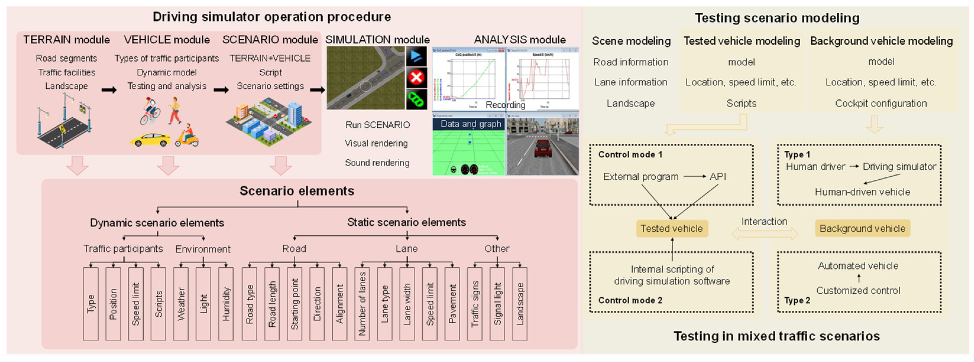
3.1.1. Framework

Experiments conducted by Kalra and Paddock [55] underscore the necessity for extensive testing of AVs, highlighting the limitations of distance-based approaches. Consequently, the focus of AV testing has shifted towards scenario-based methods [33,56,57,58,59], prioritizing the examination of critical, high-risk situations crucial for evaluating safety and decision-making processes. This approach enables focused and repeated testing of low-probability “long-tail” scenarios and high-risk scenarios, ensuring a comprehensive assessment of autonomous vehicle capabilities across diverse operational conditions. This transition underscores the superior effectiveness of scenario-based testing in simulating diverse driving environments, surpassing mere cost and efficiency considerations. Therefore, the design and generation of scenarios have become the initial steps in the testing process. In the phase of mixed traffic flow, numerous potential traffic safety issues may arise from the unpredictability of HDV operations, the lack of uniform control methods among automated vehicles (AVs) of different levels, and the uncertainties stemming from interactions between HDVs and AVs [60]. Hence, this paper focuses on mixed traffic scenarios, encompassing environments characterized by interactions between AVs and HDVs. Testing in mixed traffic scenarios differs significantly from both traditional vehicle testing and the idealized future testing of fully automated AVs. A comparative summary of these distinctions is outlined in Table 1 below.
As the intelligence of transportation systems has advanced, human involvement in the driving process has significantly diminished. The roles of human drivers have evolved from active operators to supervisors, often becoming passive observers or completely disengaging from the driving task. Consequently, vehicle-to-vehicle interactions now encompass varying degrees of autonomous driving technology [61]. Traditional interactions limited to human-driven vehicles (HDV-HDV) have given way to interactions involving vehicles with diverse levels of autonomous driving capabilities. Similar to human drivers, who undergo assessments and licensure before operating on public roads, autonomous vehicles, as they assume more driving responsibilities, also require specific assessment criteria.
Therefore, alongside traditional vehicle-centric testing paradigms such as wind tunnel experiments and collision assessments, it is increasingly imperative to integrate testing elements that address human–vehicle interactions. Moreover, unlike the homogeneity and standardization typical of traditional and idealized intelligent traffic scenarios, mixed traffic environments exhibit disparities in automation levels and manufacturing standards, rendering interactions more vulnerable to safety challenges. Consequently, refining testing protocols becomes critical in mixed traffic scenarios. Real-world vehicle testing in mixed traffic settings presents logistical challenges and significant costs, underscoring the need for reliable simulation or X-in-the-loop testing to ensure safety and feasibility.
At the core of this testing paradigm lies the creation of testing scenarios. The approach for generating mixed traffic scenarios in this study draws inspiration from scenario generation processes used in driving simulation software and incorporates the conceptual framework outlined earlier. This architectural framework is illustrated in Figure 1 below.
Figure 1 illustrates the methodology for creating mixed traffic scenarios and conducting autonomous driving tests. Initially, the analysis involves examining the operational procedures of the driving simulator and identifying critical scenario elements. Constraints are then established to tailor these elements for AV testing scenarios. The modeling of testing scenarios entails developing tested vehicle (TV) and background vehicle (BV) models for the scene. Ultimately, the interaction between human-driven and automated vehicles is facilitated through the driving simulator.

3.1.2. Scenario Modeling

Following the framework of scenario elements, testing scenario modeling is conducted through the development of a scene model, a TV model, and a BV model. The details of the scenario modeling are as follows:
  • Scene modeling: This involves defining critical road characteristics such as road type, length, starting coordinates, direction, and alignment. Lane specifications include the number of lanes, lane types, permissible vehicle types, lane width, speed limits, and pavement materials. Additionally, the modeling includes surrounding infrastructures such as buildings, integrated traffic signage, street lights, trees, and other static objects. Environmental conditions such as weather, lighting, and air quality are meticulously adjusted to simulate various driving conditions. Collectively, these elements construct a comprehensive and realistic testing environment, facilitating detailed evaluations of automated vehicles’ performance across diverse simulated driving scenarios.
  • TV modeling: Modeling the TV is a complex process tailored to meet specific testing scenario requirements. This process entails selecting the TV’s type, brand, model, and color, and positioning it within the designated driving lane at predetermined coordinates. The TV is also subject to speed constraints, typically aligned with the lane’s speed limit. The TV’s planning and decision-making model is structured into a three-tier system: global path planning generates an initial path, behavioral decisions respond to environmental factors, and a trajectory adheres to specific constraints. Software scripting functions then control the TV, ensuring the model accurately reflects real-world driving complexity and responds dynamically to elements introduced in testing scenarios.
  • BV modeling: Following the setup of static scenario elements, attention shifts to dynamic scenarios critical for assessing AV driving capabilities. These dynamic scenarios create varied environmental conditions for the TV, ensuring comprehensive testing across diverse contexts. Simulation data from these scenarios provide a holistic evaluation of model performance. BV behavior significantly influences the TV within these dynamic scenarios, with BVs controlled by human drivers using the simulator, introducing realistic driving variations in judgment and behavior.

3.1.3. Testing Method of AV Decision and Planning Model

The testing method for the AV planning and decision-making model utilizes generated scenarios within a driving simulator to create a realistic and immersive virtual driving environment. Experimenters interact with this environment through the simulator’s controls, embedding the AV planning and decision-making model for testing in mixed traffic scenarios. This setup involves two vehicle types: the BV and the TV. The BV is operated by a human driver using a compact driving cockpit equipped with realistic controls such as a steering wheel, transmission, and switches (Figure 2a). This setup enables real-time interaction with the virtual environment, including speed and directional adjustments.
Conversely, the TV is virtually represented in SCANeR Studio and controlled through scripting functions. The model implementation employs a tree-view structure comprising Rules, Conditions, Actions, and Functions (Figure 2b), enabling dynamic and customizable scenarios incorporating road characteristics, vehicle positions, and weather conditions. Detailed scripting within SCANeR Studio enhances control over the TV, ensuring precise evaluation of AV behavior and responsiveness under complex driving conditions.

3.2. Evaluation Method

The evaluation method consists of two components: evaluation indicators and evaluation standards. Evaluation indicators assess the performance of AVs, while evaluation standards define the acceptable ranges for these indicators and are used to measure the testing outcomes.

3.2.1. Evaluation Indicator

This paper categorizes evaluation indicators into two types: qualitative and quantitative. According to the evaluation standards, if all qualitative indicators meet the required thresholds, scores from both qualitative and quantitative indicators are combined to determine the total evaluation score. Conversely, if any qualitative indicator fails to meet these thresholds, the overall testing outcome is deemed unsatisfactory.
  • Qualitative indicators. Qualitative indicators evaluate the safety of the TV, including its compliance with regulations and rules, and its adherence to the behavioral attributes expected of the test item.
  • Safety indicator Q.
During the testing, the position coordinates (xn, yn) of the center point of TV and the position coordinates (xn−1, yn−1) of the center point of BV need to be extracted, then the real-time distance D1 between the two vehicles can be calculated as follows:
D 1 = ( x n x n 1 ) 2 + ( y n y n 1 ) 2 l n + l n 1 2
where ln denotes the length of the testing vehicle body, set to 4.95 m, and ln−1 denotes the length of the testing vehicle ahead, set to 2.07 m.
Furthermore, the theoretical safety distance Gapsafe, and the safety indicator Q also can be calculated as follows:
Q = D 1 G a p s a f e
  • Distance D2 from the contour of the vehicle to the edge of the roadway.
During the testing, the position coordinates (xn, yn) of the center point of TV and the ordinate yb of the edge of the roadway are extracted, and then, the distance from the contour of the vehicle to the edge of the roadway can be calculated as follows:
D 2 = y n y b w n 2
where wn denotes the width of the TV.
  • Distance D3 from the vehicle contour to the roadway boundary line.
During the testing, the position coordinates (xn, yn) of the TV center point and the ordinate yf of the roadway boundary line are extracted, and then the distance from the vehicle contour to the roadway edge line can be calculated as follows:
D 3 = y f y n w n 2
  • Behavior attribute indicator G.
It is determined according to the expected behavior of TV in the testing; generally, it is the difference in actual value and theoretical safety value.
G = X 0 X s a f e
where X0 denotes the actual value of the behavior attribute of TV, and Xsafe denotes the theoretical safety value of the behavior attribute.
2.
Quantitative indicators. Quantitative indicators are used to evaluate the comfort level of TV and the completion efficiency of the expected behavior of the tested item.
  • Expected behavior completion efficiency u.
It can be achieved through the actual value of the behavior attribute indicator divided by its maximum range as follows:
u = G G max G min
where Gmax and Gmin, respectively, denote maximum and minimum boundary values within the allowable range of behavioral attribute indicators.
  • Comfort indicator j.
In an autonomous driving environment, the comfort indicator is a key factor in evaluating the driving ability of an AV. The comfort indicator can be judged by the maximum acceleration in the lateral and longitudinal directions.
j x = a x ˜ a ˜ x max
j y = a y ˜ a ˜ y max
where jx denotes the comfort indicator of the tested vehicle in the longitudinal direction, jy denotes the comfort indicator of the tested vehicle in the lateral direction, ax denotes the maximum longitudinal acceleration of the tested vehicle, set to 3 m/s2, a ˜ x max denotes the maximum allowable longitudinal acceleration in comfortable, ay denotes the maximum lateral acceleration of the tested vehicle, set to 5 m/s2, and a ˜ y max denotes the maximum lateral acceleration allowed in comfortable.

3.2.2. Evaluation Criteria

  • Safety evaluation. The actual distance between TV and BV must be no closer than the theoretical safe distance, namely,
    Q > 0
  • Violation evaluation. The outline of the vehicle must not cross the edge of the roadway and the boundary line of the roadway, namely,
    D 2 > 0 , D 3 > 0
  • Behavioral attribute evaluation. Determine the range of behavioral attribute indicators based on experimental conditions. The range is used as the benchmark of calculation efficiency, and the real result in the testing should be in the range.
G 1 < G < G 2
where G1 denotes the minimum boundary value of the expected behavior attribute, and G2 denotes the maximum boundary value of the expected behavior attribute.
4.
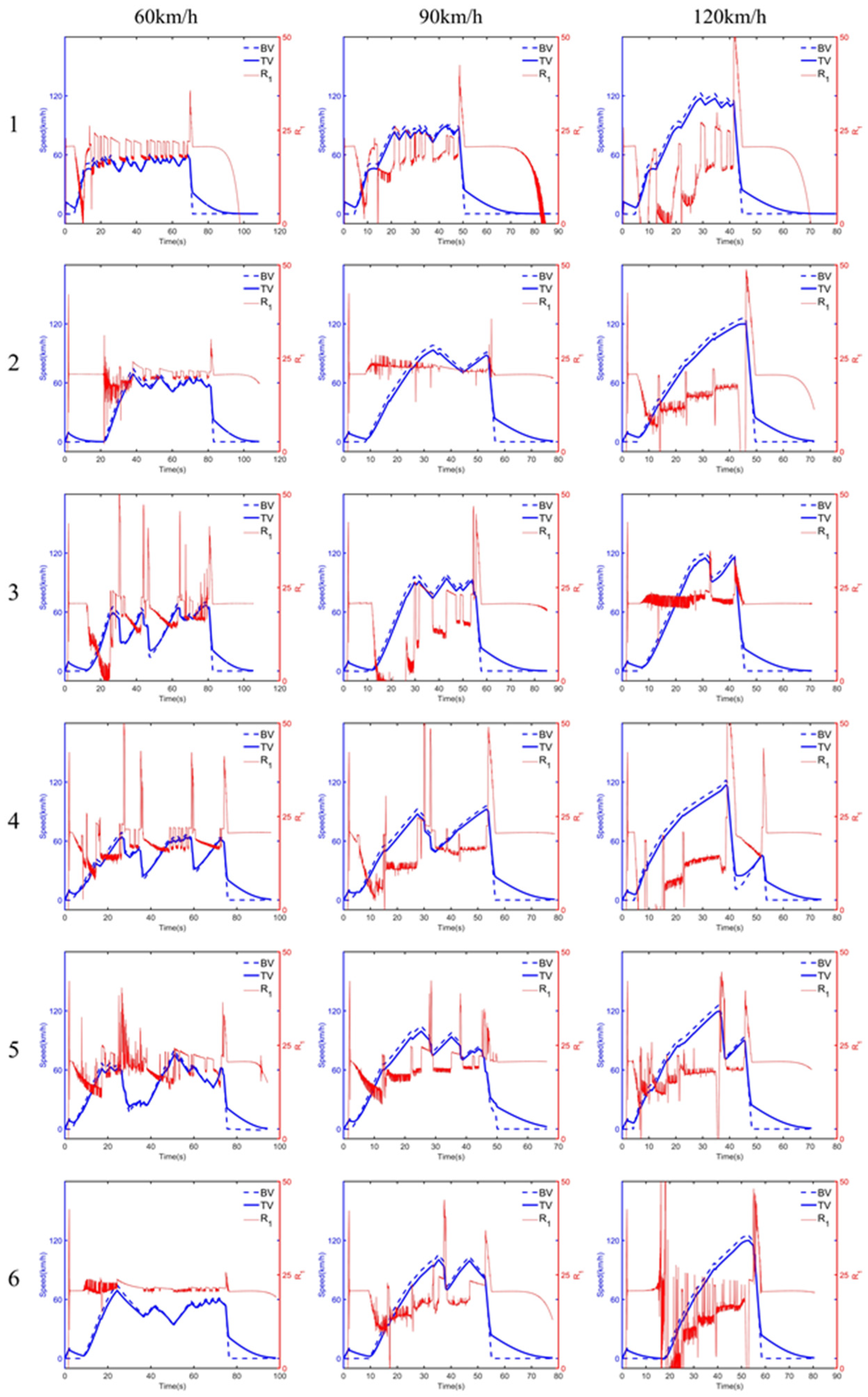
Efficiency evaluation. Set a total score of w1. According to the proportional relationship, the corresponding scores R1 can be achieved as follows:
R 1 = ( 1 u ) × w 1
5.
Comfort evaluation. The total score can be set to w2. The lateral and longitudinal comfort indicator scores each account for half. According to the proportional relationship, the longitudinal comfort score value Rx, the lateral comfort score value Ry, and the final score R2 can be obtained.
R x = ( 1 j x ) × w 2 2
R 2 = R x + R y

4. Method Verification

4.1. Model under Testing

The car-following model is a theoretical framework that employs dynamic methods to analyze the behavior of vehicles traveling in a single lane without the ability to overtake. This section verifies the proposed method using three classic car-following models: the GM model, the Gipps model, and the Fuzzy Reasoning model.
  • GM model. Developed in the late 1950s, the GM model is characterized by its simplicity and clear physical interpretation [62]. This pioneering model, significant in the early research of car-following dynamics, derives from driving dynamics models. It introduces a concept wherein the “reaction”—expressed as the acceleration or deceleration of the following vehicle—is the product of “sensitivity” and “stimulation”. Here, “stimulation” is defined by the relative speed between the following and leading vehicles, while “sensitivity” varies based on the model’s application consistency. The general formula is outlined below,
    a n + 1 t + T = c v n + 1 m t + T Δ v t Δ x l t
    where an+1(t + T) denotes the acceleration of the vehicle n + 1 at t + T, vn+1(t + T) denotes the speed of the vehicle n + 1 at t + T,v(t) denotes the speed difference between the vehicle n and the vehicle n + 1 at t, ∆x(t) denotes the distance between the vehicle n and the vehicle n + 1 at t, and c, m, l are constants.
It is assumed that acceleration is proportional to the speed difference between two vehicles, and inversely proportional to the distance between the heads of the two vehicles. And at the same time, it is directly affected by its own speed.
2.
Gipps model. Originating from the safety distance model, the Gipps car-following model [63] utilizes classical Newton’s laws of motion to determine a specific following distance, diverging from the stimulation-response relationship used in the GM model. This model computes the safe speed for the TV relative to the vehicle ahead (BV) by imposing limitations on driver and vehicle performance. These limitations guide the TV in selecting a driving speed that ensures it can safely stop without rear-ending the preceding vehicle in case of a sudden halt. The mathematical expression of this model is outlined below,
v n ( t + τ ) = min v n ( t ) + 2.5 a n τ ( 1 v n ( t ) V n ) 0.025 + v n ( t ) V n b n ( τ 2 + θ ) + b n 2 ( τ 2 + θ ) 2 + b n 2 x n 1 ( t ) x n ( t ) S n 1 τ v n ( t ) + v n 1 2 ( t ) b n 1
where vn(t) denotes the speed of vehicle n at t, an denotes the maximum acceleration of vehicle n, Vn denotes the speed limit of the vehicle n in the current design scenario, bn denotes the maximum deceleration of the vehicle n, bn−1 denotes the maximum deceleration of the vehicle n − 1, xn(t) denotes the position of vehicle n at t, Sn−1 denotes the effective length of the vehicle n − 1, τ denotes the reaction time of the vehicle n − 1, θ denotes the additional reaction time of the vehicle n − 1 to ensure safety.
3.
Fuzzy Reasoning model. Initially proposed by [64], the Fuzzy Reasoning model focuses on analyzing driving behaviors by predicting the driver’s future logical reasoning. This model fundamentally explores the relationship between stimulus and response, similar to other behavioral models. A distinctive characteristic of the Fuzzy Reasoning model is its use of fuzzy sets to manage inputs. These fuzzy sets, which partially overlap, categorize the degree of membership for each input variable. The mathematical formulation of the model is presented below,
If ∆x is appropriate, then,
a n , i = ( Δ v i + a n 1 , i × T ) / γ
where ∆x denotes the distance difference between the two vehicles, an,i denotes the acceleration of vehicle n at time i, an−1,i denotes the acceleration of vehicle n−1 at time i, ∆vi denotes the speed difference between the two vehicles, T denotes the reaction time, which is 1 s, and TV expects to catch up with the preceding vehicle within time γ; here, it is 2.5 s.
If ∆x is not appropriate, ai will decrease 0.3 m/s2 as ∆x decreases by one level, and it will increase 0.3 m/s2 as ∆x increases by one level.
a n , i = Δ v i + a n 1 , i × T γ + 0.3 Δ x

4.2. Mixed Traffic Scenario Construction

This paper utilizes SCANeR Studio and the compact driving cockpit CDS-650 as experimental platforms. SCANeR Studio is a comprehensive driving simulation software package renowned for its ergonomic interface, suitable for simulating a wide range of vehicles from light to heavy. It is extensively used in vehicle ergonomics, advanced engineering studies, road traffic research and development, as well as human factor studies and driver training.
SCANeR Studio integrates robust scenario generation logic essential for AV testing, enhancing the operational efficiency required for scenario creation and simulation experiments. The operational process within SCANeR Studio for scenario generation and simulation experiments comprises five modules: Terrain, Vehicle, Scenario, Simulation, and Analysis.
Scene model. A scene model is designed based on the characteristics of the car-following model and the specific requirements of AV testing. To enhance the realism and immersion of mixed driving testing scenarios, the roadside landscape includes office buildings, schools, and additional structures, interspersed with green trees and bushes. Weather conditions are set to sunny, with parameters such as snow, rain, clouds, and fog all set to 0%, and light set to 80%. The scenario elements are detailed in Table 2.
The schematic diagram of the scenario model is shown in Figure 3.
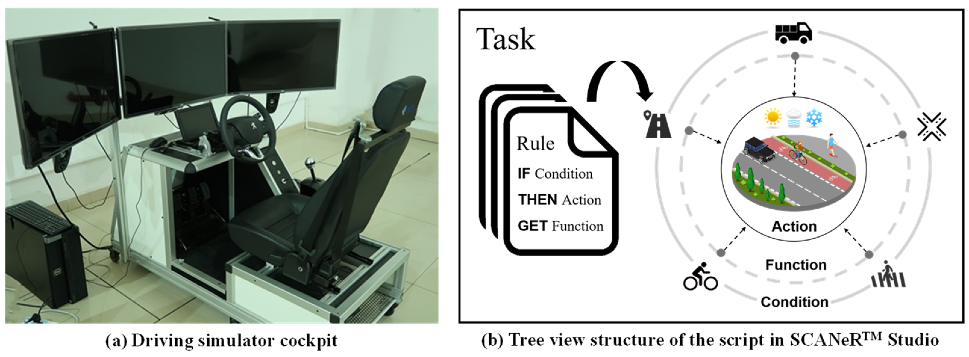
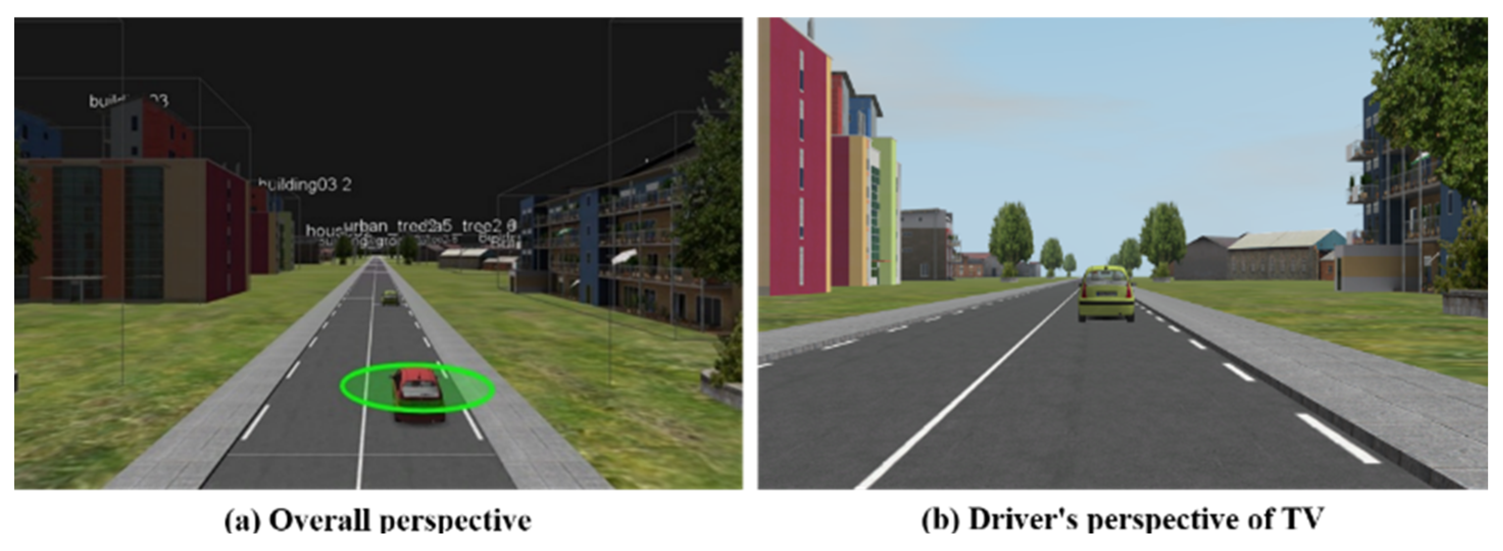
  • TV model. The vehicle selected as the TV in SCANeR Studio is the “Citroen_C3_Green”. The TV is positioned at the starting point of the road. Speed limits used in this study are set at 60 km/h, 90 km/h, and 120 km/h. Custom control of the TV is implemented through scripting based on the car-following model mentioned earlier.
  • BV model. The vehicle designated as the background vehicle (BV) in SCANeR Studio is the “Citroen_C3_Red”. The BV is placed 20 m in front of the TV and is controlled by a human driver using the driving simulator. Prior to the experiment, the following procedures are conducted: (1) Ensure the proper functioning of the driving simulator equipment. (2) Set the speed limit of TV. (3) Align the BV’s speed limit with that of the TV. (4) Start the BV and gradually accelerate to the speed limit according to driving habits. During this process, the BV can be accelerated and decelerated irregularly. (5) Towards the end of the road (approximately 50 m from the endpoint), initiate emergency braking maneuvers to decelerate the BV’s speed to zero. (6) Terminate the simulation, and the testing ends. The total travel distance covered by the BV throughout the experiment is approximately 980 m. Prior to formally commencing the experiment, preliminary trials were conducted with each participant’s session duration limited to 30 min. The successful completion of these preliminary trials indicated that the experiment duration was generally within the tolerable range for participants. This precaution aimed to mitigate potential discomfort or dizziness that participants might experience during the experiment.

4.3. Mixed Traffic Scenario Construction

  • Safety evaluation. The theoretical safety distance of Gapsafe is as follows:
    G a p s a f e = v 1 t τ 1 + v 1 t 2 2 b 1 v 0 t 2 2 b 0
    where, Gapsafe denotes the safety distance of TV, b0 denotes the maximum deceleration of BV, b1 denotes the maximum deceleration of TV, τ1 denotes the reaction time of the driver of TV, v0(t) denotes the speed of BV at time t, and v1(t) denotes the traveling speed of TV at time t.
In the safety evaluation, the score is set to 15. As in Formula (9), when the actual distance between TV and BV is not less than the theoretical safe distance, the safety performance is qualified.
2.
Violation evaluation. The total score for this section is set at 30 points. As in Formula (10), the contour of the vehicle does not cross the edge of the roadway and the boundary line of the roadway, the evaluation is qualified. If D2 > 0, 15 would be obtained. Similarly, if D3 > 0, 15 would be obtained.
3.
Car-following characteristic evaluation. In the car-following project testing, the car-following characteristic indicator G is expressed by the difference between D1 and the theoretical safety distance Gapsafe.
G = D 1 G a p s a f e
In the evaluation of car-following characteristics, the total score is set to 15. When the real driving track of the tested vehicle is within a reasonable range, it is determined that it meets the following characteristics: the left boundary of the range is the trajectory of the safe driving distance, and the right boundary is the trajectory of the safe driving distance translated by 0.2 times of the theoretical safety distance, namely,
0 < G < 0.2 G a p s a f e
4.
Car-following efficiency evaluation. The car-following efficiency indicator u is expressed by the difference between D1 and Gapsafe divided by 0.2 times Gapsafe.
u t = D 1 t G a p s a f e t 0.2 G a p s a f e t
where ut denotes the efficiency of sampling point t during the driving process, D 1 t denotes the actual distance between the two vehicles at point t, G a p s a f e t denotes the theoretical safe distance at point t.
u = u 1 + u 2 + + u t + u n n
where u denotes the average efficiency, and n is the number of sampling points.
In the car-following efficiency evaluation, a total score of 20 points is set. According to the proportional relationship, the score value R1 corresponding to different values of efficiency can be obtained.
R 1 = ( 1 u ) × 20
5.
Comfort evaluation. A total score of 20 points is set, of which the horizontal and vertical comfort indicator scores each account for 10 points. According to the proportional relationship, the longitudinal comfort score Rx, the lateral comfort score Ry, and the final score R2 can be obtained.
R x = ( 1 j x ) × 10
R y = ( 1 j y ) × 10
R 2 = R x + R y
According to the above evaluation indicators and evaluation criteria, the results of the car-following ability evaluation are shown in Table 3 below.

4.4. Results

The experimental design aims to evaluate the car-following model of the TV at three different speed limits: 60 km/h, 90 km/h, and 120 km/h. Each comprehensive test group comprises nine experiments, involving three distinct models and the three specified speed limits. This setup results in a total of 54 test groups, with six different drivers conducting each group test.
Participants aged from 22 to 25, with 0 to 3 years of driving experience, and a balanced gender distribution, operate the simulator based on their individual driving habits and abilities. The experiment does not strictly categorize participants by gender, age, or driving experience.
In the setup, the BV is designated as vehicle No. 0, and the TV as vehicle No. 1. Figure 4a displays the overall scenario effect with the inclusion of both TV and BV, while Figure 4b offers a view from the driver’s perspective of the TV during the tests.
The experimental results from six groups of experiments conducted by six participants have been compiled, showing the total evaluation scores (R) for the Gipps model, GM model, and Fuzzy Reasoning model under speed limits of 60 km/h, 90 km/h, and 120 km/h, as presented in Table 4.
From the data in Table 4, further analysis is warranted. Average scores for the Gipps model are 74.0677, 71.5985, and 67.1336 under speed limits of 60 km/h, 90 km/h, and 120 km/h, respectively. The experimental results indicate that neither the GM model nor the Fuzzy Reasoning model met the qualifying criteria, particularly falling short on safety indicators. Consequently, in cases where qualitative benchmarks are not met, scores for their car-following efficiency and comfort metrics are not computed. Hence, the scores for the GM model and Fuzzy Reasoning model are derived from the sum of scores for car- following characteristics (15 points) and violation (two sub-items, 15 × 2 = 30 points), totaling 45 points. Given that the safety evaluation criteria employed in this study are derived from the safety-distance model, specifically rooted in the Gipps model, which demonstrates superior safety performance compared to the GM and Fuzzy Reasoning models, these findings further affirm the efficacy of the evaluation methodology utilized. Given that the safety evaluation criteria employed in this study are derived from the safety-distance model, specifically rooted in the Gipps model, which demonstrates superior safety performance compared to the GM and Fuzzy Reasoning models, these findings further corroborate the efficacy of the evaluation methodology utilized.
Furthermore, in order to study the relationship between car-following efficiency, comfort and driving speed, the average scores of the six groups of experiments of R1 and R2 based on the Gipps model at 60 km/h, 90 km/h and 120 km/h speed limits, and data results are shown in Table 5.
From Table 5, the average scores of R1 in the six experiments under the speed limit of 60 km/h, 90 km/h, and 120 km/h based on the Gipps model are 9.2454, 8.4706, and 3.5456, respectively. Correspondingly, the average scores of R2 are 4.8223, 3.1283, and 2.3991, respectively. It can be seen that the car-following efficiency and comfort level of the Gipps model decrease with the increment in driving speed.
The speed change curves for the BV, the TV, and the car-following efficiency score (R1) during the experiment are depicted in Figure 5. The blue dotted line represents the BV’s speed curve, the blue solid line represents the TV’s speed curve, and the red line represents the score of the car-following efficiency indicator. If speed decreases, R1 increases sharply, which further verifies the inverse relationship between the car-following efficiency and the driving speed.

4.5. Limitations and Outlook

This study has focused on relatively simple and fundamental models for both model selection and scenario construction, which may have constrained the richness and generalizability of the results. The choice of classic models and the restriction to interactions between only two vehicles in platooning scenarios limit the complexity and diversity of simulated driving behaviors. Future research endeavors will need to address these limitations by exploring more complex and varied scenarios, as well as refining model selection and calibration processes. In particular, advancing research should emphasize the study of intricate driving environments that better reflect real-world complexities. This includes scenarios with heterogeneous traffic compositions and varying levels of vehicle autonomy, aiming to capture a broader spectrum of driving behaviors and interactions.
Moreover, in practical applications, it is essential for practitioners and policymakers to consider the implications of road speed limits and the driving speeds of AVs. This aspect is crucial as it directly impacts traffic efficiency, safety, and user acceptance. Future studies should thus prioritize detailed investigations into optimal speed profiles for AVs to ensure safe, smooth, and efficient integration into mixed traffic environments.

5. Conclusions

Testing AVs is crucial to ensure their safe and efficient operation across various road traffic scenarios. Initially, field tests used real vehicles, but virtual testing has gained traction due to its safety, repeatability, and cost-effectiveness. However, both methods face challenges in creating realistic mixed traffic scenarios. To address these limitations, we propose a new testing method using a driving simulator. In this method, a human driver manipulates the simulator’s cockpit components to interact with the AV’s planning and decision-making model in SCANeR Studio, effectively simulating mixed traffic scenarios with human driver randomness.
Experiments employing three classic car-following models—the GM model, the Fuzzy Reasoning model, and the Gipps model—yielded significant findings. Firstly, safety evaluation criteria favor the Gipps model, with experimental results confirming its superior performance over the GM and Fuzzy Reasoning models, consistent with theoretical expectations. Thus, the outcomes derived from the driving simulator are considered valid. Secondly, the car-following efficiency and comfort level of the Gipps model decline as driving speeds increase. Future research could focus on the secondary development of driving simulator software to allow custom control of tested vehicles and the integration of sensors and other software and hardware components for comprehensive AV testing.
Overall, the proposed method using the driving simulator proves to be a reasonable and effective approach for assessing AVs’ planning and decision-making models in mixed traffic scenarios, thereby enhancing the safety and efficiency of interactions between HDVs and AVs.

Author Contributions

Conceptualization, Y.Z. and X.S.; methodology, Y.Z., Y.S. and X.S.; validation, Y.Z., Y.S. and X.S.; formal analysis, Y.Z., X.S. and Y.S.; investigation, Y.Z. and X.S.; resources, X.S.; data curation, Y.Z. and Y.S.; writing—original draft preparation, Y.Z. and Y.S.; writing—review and editing, X.S.; visualization, Y.Z.; supervision, X.S. and Z.Y.; project administration, X.S. and Z.Y.; funding acquisition, X.S. and Z.Y. All authors have read and agreed to the published version of the manuscript.

Funding

This study is sponsored by the National Key R&D Program of China (2022YFB4300300), the National Natural Science Foundation of China (52072070, 52202410, 52172342), the Nanjing Science and Technology Program (202309010), the Anhui Provincial Key R&D Program (202304a05020062), the Yangtze River Delta Collaborative Science and Technology Innovation Project (2023CSJGG0900), and the Fundamental Research Funds for the Central Universities (2242024RCB0047, 2242023R40057).

Data Availability Statement

Data and software are not available.

Conflicts of Interest

The authors declare no conflicts of interest.

References

  1. Liu, W.; Hua, M.; Deng, Z.; Meng, Z.; Huang, Y.; Hu, C.; Song, S.; Gao, L.; Liu, C.; Shuai, B. A Systematic Survey of Control Techniques and Applications in Connected and Automated Vehicles. IEEE Internet Things J. 2023, 10, 21892–21916. [Google Scholar] [CrossRef]
  2. Shi, H.; Zhou, Y.; Wang, X.; Fu, S.; Gong, S.; Ran, B. A Deep Reinforcement Learning-based Distributed Connected Automated Vehicle Control under Communication Failure. Comput. Aided Civ. Infrastruct. Eng. 2022, 37, 2033–2051. [Google Scholar] [CrossRef]
  3. Ren, R.; Li, H.; Han, T.; Tian, C.; Zhang, C.; Zhang, J.; Proctor, R.W.; Chen, Y.; Feng, Y. Vehicle Crash Simulations for Safety: Introduction of Connected and Automated Vehicles on the Roadways. Accid. Anal. Prev. 2023, 186, 107021. [Google Scholar] [CrossRef]
  4. Sohrabi, S.; Khodadadi, A.; Mousavi, S.M.; Dadashova, B.; Lord, D. Quantifying the Automated Vehicle Safety Performance: A Scoping Review of the Literature, Evaluation of Methods, and Directions for Future Research. Accid. Anal. Prev. 2021, 152, 106003. [Google Scholar] [CrossRef]
  5. Wang, L.; Zhong, H.; Ma, W.; Abdel-Aty, M.; Park, J. How Many Crashes Can Connected Vehicle and Automated Vehicle Technologies Prevent: A Meta-Analysis. Accid. Anal. Prev. 2020, 136, 105299. [Google Scholar] [CrossRef]
  6. Dong, C.; Wang, H.; Li, Y.; Shi, X.; Ni, D.; Wang, W. Application of Machine Learning Algorithms in Lane-Changing Model for Intelligent Vehicles Exiting to off-Ramp. Transp. A Transp. Sci. 2021, 17, 124–150. [Google Scholar] [CrossRef]
  7. National Highway Traffic Safety Administration. Summary Report: Standing General Order on Crash Reporting for Level 2 Advanced Driver Assistance Systems; US Department of Transport: Washington, DC, USA, 2022.
  8. Chougule, A.; Chamola, V.; Sam, A.; Yu, F.R.; Sikdar, B. A Comprehensive Review on Limitations of Autonomous Driving and Its Impact on Accidents and Collisions. IEEE Open J. Veh. Technol. 2023, 5, 142–161. [Google Scholar] [CrossRef]
  9. Feng, S.; Yan, X.; Sun, H.; Feng, Y.; Liu, H.X. Intelligent Driving Intelligence Test for Autonomous Vehicles with Naturalistic and Adversarial Environment. Nat. Commun. 2021, 12, 748. [Google Scholar] [CrossRef]
  10. De Gelder, E.; Op Den Camp, O. How Certain Are We That Our Automated Driving System Is Safe? Traffic Inj. Prev. 2023, 24, S131–S140. [Google Scholar] [CrossRef] [PubMed]
  11. Wei, S.; Shao, M. Existence of Connected and Autonomous Vehicles in Mixed Traffic: Impacts on Safety and Environment. Traffic Inj. Prev. 2024, 25, 390–399. [Google Scholar] [CrossRef] [PubMed]
  12. Huang, W.; Wang, K.; Lv, Y.; Zhu, F. Autonomous Vehicles Testing Methods Review. In Proceedings of the 2016 IEEE 19th International Conference on Intelligent Transportation Systems (ITSC), Rio de Janeiro, Brazil, 1–4 November 2016; IEEE: Piscataway, NJ, USA, 2016; pp. 163–168. [Google Scholar]
  13. Schilling, R.; Schultz, T. Validation of Automated Driving Functions. In Simulation and Testing for Vehicle Technology; Gühmann, C., Riese, J., Von Rüden, K., Eds.; Springer International Publishing: Cham, Switzerland, 2016; pp. 377–381. ISBN 978-3-319-32344-2. [Google Scholar]
  14. Cao, L.; Feng, X.; Liu, J.; Zhou, G. Automatic Generation System for Autonomous Driving Simulation Scenarios Based on PreScan. Appl. Sci. 2024, 14, 1354. [Google Scholar] [CrossRef]
  15. Zhang, S.; Zhou, X.; Chen, Q.; Yang, X.; Zhou, H.; Luo, L.; Luo, Y. Carsim-Based Simulation Study on the Performances of Raised Speed Deceleration Facilities under Different Profiles. Traffic Inj. Prev. 2024, 25, 810–818. [Google Scholar] [CrossRef] [PubMed]
  16. Lauer, A.R. The Psychology of Driving: Factors of Traffic Enforcement; National Academies: Washington, DC, USA, 1960. [Google Scholar]
  17. Comte, S.L.; Jamson, A.H. Traditional and Innovative Speed-Reducing Measures for Curves: An Investigation of Driver Behaviour Using a Driving Simulator. Saf. Sci. 2000, 36, 137–150. [Google Scholar] [CrossRef]
  18. Abe, G.; Richardson, J. The Influence of Alarm Timing on Braking Response and Driver Trust in Low Speed Driving. Saf. Sci. 2005, 43, 639–654. [Google Scholar] [CrossRef]
  19. Lin, T.-W.; Hwang, S.-L.; Green, P.A. Effects of Time-Gap Settings of Adaptive Cruise Control (ACC) on Driving Performance and Subjective Acceptance in a Bus Driving Simulator. Saf. Sci. 2009, 47, 620–625. [Google Scholar] [CrossRef]
  20. Choudhary, P.; Velaga, N.R. Effects of Phone Use on Driving Performance: A Comparative Analysis of Young and Professional Drivers. Saf. Sci. 2019, 111, 179–187. [Google Scholar] [CrossRef]
  21. Eriksson, A.; Stanton, N.A. Takeover Time in Highly Automated Vehicles: Noncritical Transitions to and from Manual Control. Hum. Factors 2017, 59, 689–705. [Google Scholar] [CrossRef] [PubMed]
  22. Saifuzzaman, M.; Zheng, Z. Incorporating Human-Factors in Car-Following Models: A Review of Recent Developments and Research Needs. Transp. Res. Part C Emerg. Technol. 2014, 48, 379–403. [Google Scholar] [CrossRef]
  23. Schieben, A.; Heesen, M.; Schindler, J.; Kelsch, J.; Flemisch, F. The Theater-System Technique: Agile Designing and Testing of System Behavior and Interaction, Applied to Highly Automated Vehicles. In Proceedings of the 1st International Conference on Automotive User Interfaces and Interactive Vehicular Applications, Essen, Germany, 21–22 September 2009; ACM: New York, NY, USA, 2009; pp. 43–46. [Google Scholar]
  24. Elrofai, H.; Worm, D.; Op Den Camp, O. Scenario Identification for Validation of Automated Driving Functions. In Advanced Microsystems for Automotive Applications 2016; Schulze, T., Müller, B., Meyer, G., Eds.; Lecture Notes in Mobility; Springer International Publishing: Cham, Switzerland, 2016; pp. 153–163. ISBN 978-3-319-44765-0. [Google Scholar]
  25. Feng, S.; Feng, Y.; Yu, C.; Zhang, Y.; Liu, H.X. Testing Scenario Library Generation for Connected and Automated Vehicles, Part I: Methodology. IEEE Trans. Intell. Transp. Syst. 2020, 22, 1573–1582. [Google Scholar] [CrossRef]
  26. Feng, S.; Feng, Y.; Sun, H.; Zhang, Y.; Liu, H.X. Testing Scenario Library Generation for Connected and Automated Vehicles: An Adaptive Framework. IEEE Trans. Intell. Transp. Syst. 2022, 23, 1213–1222. [Google Scholar] [CrossRef]
  27. Feng, S.; Feng, Y.; Yan, X.; Shen, S.; Xu, S.; Liu, H.X. Safety Assessment of Highly Automated Driving Systems in Test Tracks: A New Framework. Accid. Anal. Prev. 2020, 144, 105664. [Google Scholar] [CrossRef] [PubMed]
  28. Feng, S.; Feng, Y.; Sun, H.; Bao, S.; Zhang, Y.; Liu, H.X. Testing Scenario Library Generation for Connected and Automated Vehicles, Part II: Case Studies. IEEE Trans. Intell. Transp. Syst. 2020, 22, 5635–5647. [Google Scholar] [CrossRef]
  29. Fellner, A.; Krenn, W.; Schlick, R.; Tarrach, T.; Weissenbacher, G. Model-Based, Mutation-Driven Test-Case Generation Via Heuristic-Guided Branching Search. ACM Trans. Embed. Comput. Syst. 2019, 18, 1–28. [Google Scholar] [CrossRef]
  30. Rocklage, E.; Kraft, H.; Karatas, A.; Seewig, J. Automated Scenario Generation for Regression Testing of Autonomous Vehicles. In Proceedings of the 2017 IEEE 20th International Conference on Intelligent Transportation Systems (ITSC), Yokohama, Japan, 16–19 October 2017; IEEE: Piscataway, NJ, USA, 2017; pp. 476–483. [Google Scholar]
  31. Gao, F.; Duan, J.; He, Y.; Wang, Z. A Test Scenario Automatic Generation Strategy for Intelligent Driving Systems. Math. Probl. Eng. 2019, 2019, 3737486. [Google Scholar] [CrossRef]
  32. Zhao, D.; Huang, X.; Peng, H.; Lam, H.; LeBlanc, D.J. Accelerated Evaluation of Automated Vehicles in Car-Following Maneuvers. IEEE Trans. Intell. Transport. Syst. 2018, 19, 733–744. [Google Scholar] [CrossRef]
  33. Donà, R.; Ciuffo, B. Virtual Testing of Automated Driving Systems. A Survey on Validation Methods. IEEE Access 2022, 10, 24349–24367. [Google Scholar] [CrossRef]
  34. Fadaie, J. The State of Modeling, Simulation, and Data Utilization within Industry: An Autonomous Vehicles Perspective. arXiv 2019, arXiv:1910.06075. [Google Scholar]
  35. Li, Y.; Yuan, W.; Zhang, S.; Yan, W.; Shen, Q.; Wang, C.; Yang, M. Choose Your Simulator Wisely: A Review on Open-Source Simulators for Autonomous Driving. IEEE Trans. Intell. Veh. 2024, 9, 4861–4876. [Google Scholar] [CrossRef]
  36. Zhong, Z.; Tang, Y.; Zhou, Y.; Neves, V.d.O.; Liu, Y.; Ray, B. A Survey on Scenario-Based Testing for Automated Driving Systems in High-Fidelity Simulation. arXiv 2021, arXiv:2112.00964. [Google Scholar]
  37. Gafert, M.; Mirnig, A.G.; Fröhlich, P.; Tscheligi, M. TeleOperationStation: XR-Exploration of User Interfaces for Remote Automated Vehicle Operation. In Proceedings of the CHI Conference on Human Factors in Computing Systems Extended Abstracts, New Orleans, LA, USA, 29 April–5 May 2022; ACM: New York, NY, USA, 2022; pp. 1–4. [Google Scholar]
  38. Goedicke, D.; Bremers, A.W.D.; Lee, S.; Bu, F.; Yasuda, H.; Ju, W. XR-OOM: MiXed Reality Driving Simulation with Real Cars for Research and Design. In Proceedings of the CHI Conference on Human Factors in Computing Systems, New Orleans, LA, USA, 29 April–5 May 2022; ACM: New York, NY, USA, 2022; pp. 1–13. [Google Scholar]
  39. Kim, G.; Yeo, D.; Jo, T.; Rus, D.; Kim, S. What and When to Explain?: On-Road Evaluation of Explanations in Highly Automated Vehicles. In Proceedings of the ACM on Interactive, Mobile, Wearable and Ubiquitous Technologies, Cancún, Mexico, 8–12 October 2023; IMWUT: Cancún, Mexico, 2023; Volume 7, pp. 1–26. [Google Scholar] [CrossRef]
  40. Di, X.; Shi, R. A Survey on Autonomous Vehicle Control in the Era of Mixed-Autonomy: From Physics-Based to AI-Guided Driving Policy Learning. Transp. Res. Part C Emerg. Technol. 2021, 125, 103008. [Google Scholar] [CrossRef]
  41. Mohammad Miqdady, T.F. Studying the Safety Impact of Sharing Different Levels of Connected and Automated Vehicles Using Simulationbased Surrogate Safety Measures. Ph.D. Thesis, Universidad de Granada, Granada, Spain, 2023. [Google Scholar]
  42. Briefs, U. Mcity Grand Opening. Res. Rev. 2015, 46, 1–3. [Google Scholar]
  43. Connolly, C. Instrumentation Used in Vehicle Safety Testing at Millbrook Proving Ground Ltd. Sens. Rev. 2007, 27, 91–98. [Google Scholar] [CrossRef]
  44. Jacobson, J.; Eriksson, H.; Janevik, P.; Andersson, H. How Is Astazero Designed and Equipped for Active Safety Testing? In Proceedings of the 24th International Technical Conference on the Enhanced Safety of Vehicles (ESV) National Highway Traffic Safety Administration, Gothenburg, Sweden, 8–11 June 2015. [Google Scholar]
  45. Feng, Q.; Kang, K.; Ding, Q.; Yang, X.; Wu, S.; Zhang, F. Study on Construction Status and Development Suggestions of Intelligent Connected Vehicle Test Area in China. Int. J. Glob. Econ. Manag. 2024, 3, 264–273. [Google Scholar] [CrossRef]
  46. Fremont, D.J.; Kim, E.; Pant, Y.V.; Seshia, S.A.; Acharya, A.; Bruso, X.; Wells, P.; Lemke, S.; Lu, Q.; Mehta, S. Formal Scenario-Based Testing of Autonomous Vehicles: From Simulation to the Real World. In Proceedings of the 2020 IEEE 23rd International Conference on Intelligent Transportation Systems (ITSC), Rhodes, Greece, 20–23 September 2020; IEEE: Piscataway, NJ, USA, 2020; pp. 1–8. [Google Scholar]
  47. Vishnukumar, H.J.; Butting, B.; Müller, C.; Sax, E. Machine Learning and Deep Neural Network—Artificial Intelligence Core for Lab and Real-World Test and Validation for ADAS and Autonomous Vehicles: AI for Efficient and Quality Test and Validation. In Proceedings of the 2017 Intelligent Systems Conference (IntelliSys), London, UK, 7–8 September 2017; IEEE: Piscataway, NJ, USA, 2017; pp. 714–721. [Google Scholar]
  48. Tian, H.; Reddy, K.; Feng, Y.; Quddus, M.; Demiris, Y.; Angeloudis, P. Enhancing Autonomous Vehicle Training with Language Model Integration and Critical Scenario Generation. arXiv 2024, arXiv:2404.08570. [Google Scholar]
  49. Zhang, X.; Tao, J.; Tan, K.; Törngren, M.; Sánchez, J.M.G.; Ramli, M.R.; Tao, X.; Gyllenhammar, M.; Wotawa, F.; Mohan, N.; et al. Finding Critical Scenarios for Automated Driving Systems: A Systematic Mapping Study. IEEE Trans. Softw. Eng. 2023, 49, 991–1026. [Google Scholar] [CrossRef]
  50. Ma, J.; Zhou, F.; Huang, Z.; Melson, C.L.; James, R.; Zhang, X. Hardware-in-the-Loop Testing of Connected and Automated Vehicle Applications: A Use Case for Queue-Aware Signalized Intersection Approach and Departure. Transp. Res. Rec. 2018, 2672, 36–46. [Google Scholar] [CrossRef]
  51. Koppel, C.; Van Doornik, J.; Petermeijer, B.; Abbink, D. Investigation of the Lane Change Behavior in a Driving Simulator. ATZ Worldw. 2019, 121, 62–67. [Google Scholar] [CrossRef]
  52. Suzuki, H.; Wakabayashi, S.; Marumo, Y. Intent Inference of Deceleration Maneuvers and Its Safety Impact Evaluation by Driving Simulator Experiments. J. Traffic Logist. Eng. 2019, 7, 28–34. [Google Scholar] [CrossRef]
  53. Mohajer, N.; Asadi, H.; Nahavandi, S.; Lim, C.P. Evaluation of the Path Tracking Performance of Autonomous Vehicles Using the Universal Motion Simulator. In Proceedings of the 2018 IEEE International Conference on Systems, Man, and Cybernetics (SMC), Miyazaki, Japan, 7–10 October 2018; IEEE: Piscataway, NJ, USA, 2018; pp. 2115–2121. [Google Scholar]
  54. Manawadu, U.; Ishikawa, M.; Kamezaki, M.; Sugano, S. Analysis of Individual Driving Experience in Autonomous and Human-Driven Vehicles Using a Driving Simulator. In Proceedings of the 2015 IEEE International Conference on Advanced Intelligent Mechatronics (AIM), Busan, Republic of Korea, 7–11 July 2015; IEEE: Piscataway, NJ, USA, 2015; pp. 299–304. [Google Scholar]
  55. Kalra, N.; Paddock, S.M. Driving to Safety: How Many Miles of Driving Would It Take to Demonstrate Autonomous Vehicle Reliability? Transp. Res. Part A Policy Pract. 2016, 94, 182–193. [Google Scholar] [CrossRef]
  56. Stellet, J.E.; Zofka, M.R.; Schumacher, J.; Schamm, T.; Niewels, F.; Zöllner, J.M. Testing of Advanced Driver Assistance towards Automated Driving: A Survey and Taxonomy on Existing Approaches and Open Questions. In Proceedings of the 2015 IEEE 18th International Conference on Intelligent Transportation Systems, Gran Canaria, Spain, 15–18 September 2015; IEEE: Piscataway, NJ, USA, 2015; pp. 1455–1462. [Google Scholar]
  57. Hoss, M.; Scholtes, M.; Eckstein, L. A Review of Testing Object-Based Environment Perception for Safe Automated Driving. Automot. Innov. 2022, 5, 223–250. [Google Scholar] [CrossRef]
  58. Wishart, J.; Como, S.; Forgione, U.; Weast, J.; Weston, L.; Smart, A.; Nicols, G. Literature Review of Verification and Validation Activities of Automated Driving Systems. SAE Int. J. Connect. Autom. Veh. 2020, 3, 267–323. [Google Scholar] [CrossRef]
  59. Nalic, D.; Mihalj, T.; Bäumler, M.; Lehmann, M.; Eichberger, A.; Bernsteiner, S. Scenario Based Testing of Automated Driving Systems: A Literature Survey. In Proceedings of the FISITA Web Congress, Prague, Czech Republic, 14–18 September 2020; Volume 10, p. 1. [Google Scholar]
  60. Jiang, Y.; Wang, S.; Yao, Z.; Zhao, B.; Wang, Y. A Cellular Automata Model for Mixed Traffic Flow Considering the Driving Behavior of Connected Automated Vehicle Platoons. Phys. A Stat. Mech. Its Appl. 2021, 582, 126262. [Google Scholar] [CrossRef]
  61. Chen, L.; Li, Y.; Huang, C.; Li, B.; Xing, Y.; Tian, D.; Li, L.; Hu, Z.; Na, X.; Li, Z. Milestones in Autonomous Driving and Intelligent Vehicles: Survey of Surveys. IEEE Trans. Intell. Veh. 2022, 8, 1046–1056. [Google Scholar] [CrossRef]
  62. Gazis, D.C.; Herman, R.; Rothery, R.W. Nonlinear Follow-the-Leader Models of Traffic Flow. Oper. Res. 1961, 9, 545–567. [Google Scholar] [CrossRef]
  63. Gipps, P.G. A Behavioural Car-Following Model for Computer Simulation. Transp. Res. Part B Methodol. 1981, 15, 105–111. [Google Scholar] [CrossRef]
  64. Kikuchi, S.; Chakroborty, P. Car-Following Model Based on Fuzzy Inference System; Transportation Research Board: Washington, DC, USA, 1992; p. 82. [Google Scholar]
Figure 1. Mixed traffic scenario creation and AV testing method framework.
Systems 12 00298 g001
Figure 2. BV and YV control mode.
Systems 12 00298 g002
Figure 3. Schematic diagram of the scenario model (top view).
Systems 12 00298 g003
Figure 4. Scenario diagram during simulation.
Systems 12 00298 g004
Figure 5. Speed curves of the BV and the TV, and the score curves of the car-following efficiency evaluation items.
Systems 12 00298 g005
Table 1. Comparisons of three types of traffic scenarios.
Traffic ScenariosTraditional TrafficMixed TrafficIdeal Intelligent Traffic
Penetration rate of AVs0(0, 100%)100%
Vehicle automation levelsConsistent
(All HDVs)
Inconsistent
(Vehicles with different automation levels)
Consistent
(All fully autonomous vehicles)
Uniformity of testing criteriaUniformNon-uniformUniform
Types of vehicle-to-vehicle interactionHDV-HDVHDV-HDV
AV-AV
AV-HDV
AV-AV
Emphasis of testingVehicle factory testingVehicle factory testing
Driving abilities testing
Interaction capabilities testing
Vehicle factory testing
Driving abilities testing
Operational human-friendliness testing
Table 2. Scenario elements’ setup in scenario modeling.
Basic Road InformationLane InformationEnvironmental Information
Road typeUrban expresswayNumber of lanesTwo-way two-laneWeatherSunny 80%
Road length1000 mLane typeAsphalt concreteSnow, rain, clouds, and fog at 0%
Starting pointOriginType of vehiclecarLighting80%
Road directionLane width3.75 mLandscapeOffice buildings, schools;
Road alignmentStraight lineLane speed limit120 km/hGreen trees and bushes
Table 3. Evaluation results of car-following ability.
Evaluation ItemsRequirementsJudging Results
SafetyQ ≥ 015 points/Unqualified
Car-following characteristics0 < G < 0.2 Gapsafe15 points/Unqualified
ViolationD2 > 015 points/Unqualified
D3 > 015 points/Unqualified
Car-following efficiencyR1 = (1 − u) × 20R1
ComfortR2 = Rx + Ry = (2 − jxjy) × 10R2
Total scoreQualified: R = 60 + R1 + R2R
Unqualified: R = 15 × r
Note: r denotes the number of qualified qualitative indicators; car-following ability test is passed only if three qualitative evaluation items are qualified; otherwise, it fails; when the test result is qualified, the quantitative evaluation item score is valid, the total evaluation score can be calculated, Otherwise, it is unqualified and the corresponding score is less than 60.
Table 4. Experimental results.
Group 160 km/h90 km/h120 km/hGroup 260 km/h90 km/h120 km/h
Gipps Model71.430877.667645Gipps Model74.578176.783866.5414
GM Model454545GM Model454545
Fuzzy Reasoning Model454545Fuzzy Reasoning Model454545
Group 360 km/h90 km/h120 km/hGroup 460 km/h90 km/h120 km/h
Gipps Model77.339771.128772.8375Gipps Model73.810865.795363.3177
GM Model454545GM Model454545
Fuzzy Reasoning Model454545Fuzzy Reasoning Model454545
Group 560 km/h90 km/h120 km/hGroup 660 km/h90 km/h120 km/h
Gipps Model70.691168.914565.1808Gipps Model76.555669.303167.7908
GM Model454545GM Model454545
Fuzzy Reasoning Model454545Fuzzy Reasoning Model454545
Table 5. Average score of Gipps model R1 and R2.
60 km/h90 km/h120 km/h
R19.24548.47063.5456
R24.82233.12832.3991
Disclaimer/Publisher’s Note: The statements, opinions and data contained in all publications are solely those of the individual author(s) and contributor(s) and not of MDPI and/or the editor(s). MDPI and/or the editor(s) disclaim responsibility for any injury to people or property resulting from any ideas, methods, instructions or products referred to in the content.

