1. Introduction
In the Indian technical education, courses on embedded systems started in the early 1980s, studying the microprocessors 8085 and Z80, and then slowly moved to cover microcontroller 8051 and its derivatives and then proceeded to PIC, AVR and 68XX families and then finally settled on ARM and Renesas parts in recent days.
The content of all these courses focused on understanding the microprocessor/microcontroller core and many of their on-chip and off-chip peripheral functions. During their study, students concentrate mainly on the hardware aspects of the embedded systems. Mostly, the study hardware is a static design with fixed features supporting the selected target processor with the facility to study and understand peripheral functions associated with that processor.
Additionally, nowadays, the students obtain awareness on software aspects including RTOS usage, system safety and fault-tolerant features when completing their graduation. The periodical industrial interactions have exposed the students to the importance of acquiring the required software development skills on the given hardware to complete the embedded solutions, before leaving the respective colleges.
Globally, the education on hardware and software aspects of embedded systems has been addressed in many ways from different perspectives [
1,
2,
3,
4,
5]. Various embedded hardware platforms and systems have been proposed and used for education and laboratory practice on embedded systems based on microcontrollers [
4,
6,
7,
8] and Field Programmable Gate Arrays (FPGA) [
2,
3,
5].
In a prior work, CaiLimin et al. [
6] describe an embedded system course covering elements of embedded software design, real-time operating system, low-power computation and mixed-signal interfaces based on a standard ARM7TDMI microcontroller-based evaluation board. Vassiliev et al. [
8] describe an embedded system hardware based on the MCS-51 microcontroller used for education, research and real-world applications. Xiumin Shi et al. [
4] describe the research and educational activities performed using an Intel
® PXA255 processor-based hardware platform with an emphasis on porting of Linux on the hardware and interfacing the hardware elements.
The embedded software development aspects of all the above hardware are focused on the microcontroller or FPGA and their on-chip and off-chip peripheral elements only. The facility to easily create different programming scenarios with suitable complexities is not available without hardware changes. The hardware-focused software development and the limitations in creating uniquely different application scenarios make it difficult and time-consuming to acquire high-level, application-oriented, real-time programming skills in an embedded system environment. This is because the student has to first deal with the system hardware, any add-on hardware, low-level software that deals with the initializations of the on-chip peripherals and interfaces for the connected hardware, before starting with application code. All these steps consume significant time and take the focus away from the high-level application programming, which is an essential skill.
Additionally, another way of teaching the concepts of programming and embedded systems is through the usage of robotic trainers based on the LEGO Mindstorms platform and other exclusive customized hardware [
9,
10,
11]. Moreover, the limitations of using the LEGO platform for a college-level course are also discussed in [
10,
11].
Further, as discussed in [
1,
7], traditional courses on embedded systems may require additional training and practice for building up application-oriented knowledge and skills for the student to be comfortable in developing a complete embedded system. However, as detailed by [
6], computer programming courses do not address the required programming skills suitable for embedded systems because of the difference in nature between computers and embedded hardware.
In the view of developing this missing knowledge and capability, which is required to implement a complete embedded system design, a rail-network based simulation and control hardware has been developed by the authors. The hardware provides complementary learning to the traditional embedded systems trainers and is not intended to replace them. The hardware enables the creation of multiple unique programming scenarios with variability in complexity without the requirement of any hardware changes. The software development is focused on practicing the skills required for application-oriented, logical, real-time programming in an embedded system environment.
It is to be noted that, in previous work [
12], a model railroad retrofitted with sensors and control elements was used for “Providing an exciting environment for a real-time embedded systems course”. The system is envisaged as a platform for multidisciplinary student teams to work together to solve a real-world problem. Obviously, the entire exercise is an interesting and extensive challenge requiring several hundred collective hours of effort to complete.
The paper is organized as follows: In
Section 2, the rail-network simulation hardware is discussed along with the ways of train navigation using manual control and automatic control by the use of a microcontroller. In
Section 3, program development is discussed along with example scenarios describing the process.
Section 4 deals with the usefulness of simulation facilities in aiding the learning process.
Section 5 describes the methodology of evaluating the knowledge transfer to the students through training.
Section 6 chronicles the training with this platform and the evaluation of students’ performance.
Section 7 discusses the outcomes of the training. The last section concludes the findings of the paper.
2. Novel Hardware Platform Using Simulated Rail-Network
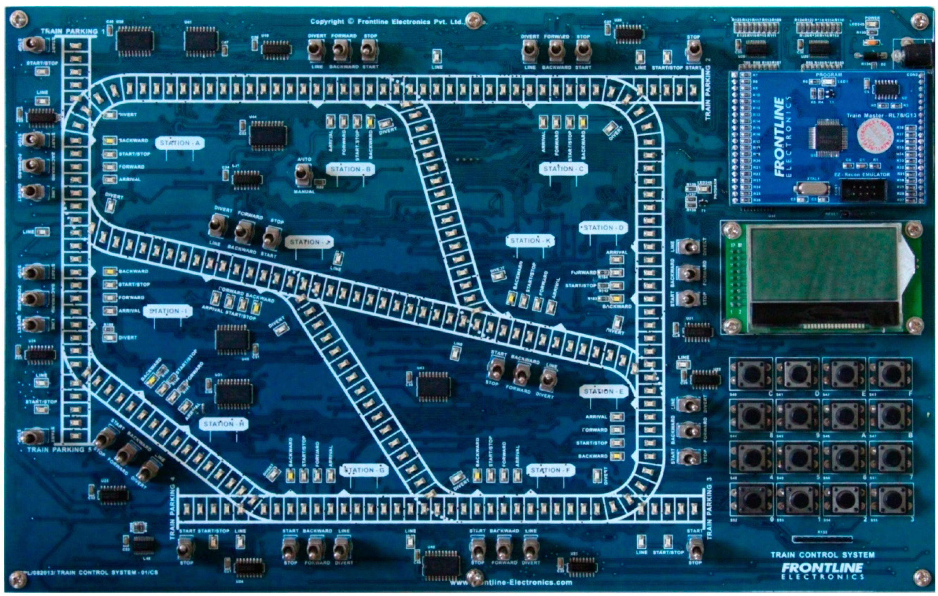
The paper presents a novel hardware platform using a simulated rail-network that contains multiple trains travelling around 11 stations following standard signals available at these stations as seen in
Figure 1. In the hardware, the movement of the trains is simulated by shifting the illumination of LEDs along the tracks. The movement of these trains is decided based on the signals at every station of the network. The navigation of these trains is monitored and controlled by a user microcontroller (16-bit Renesas RL78/G13 Microcontroller) with embedded C code written by the students. When only one train is enabled, monitoring and control of the same around different stations are easy to accomplish. The control complexity increases substantially when three or more trains are enabled to travel around the network from different parking slots. This facility introduces a dynamic nature to the target microcontroller and the real-time constraints automatically come into play during program development.
2.1. The Rail-Network
The rail-network consists of LEDs arranged in a defined track, five of which are turned on and off to represent the presence and movement of the trains. The trains are started from pre-defined spots known as parking slots. The train track has a total of 11 intersections where a train can move in one of two selectable paths. Each intersection also has a corresponding train station where the movement of the trains can be monitored and controlled.
The stations are denoted by the letters A to K. Each station has three control signals which can be manually generated using toggle switches or digitally controlled from the user microcontroller. The control signals are Start/Stop control, Forward/Backward control and Diversion/Line control. When a train enters a station, the Start/Stop control is used to stop the train or allow it to pass through the station. Forward/Backward control is used to choose the movement direction of the train. For this purpose, North and East directions are considered to be forward and moving West or South is considered to be moving in the backward direction. The North and South directions will take precedence over East and West directions. So, a train moving North-West will be considered moving Forward, while a train travelling South-East will be considered travelling in the Backward direction.
If the train needs to take a diversion in the intersection corresponding to the station, the Diversion option of the Diversion/Line control must be selected. For the train to take the straight path, the Line option must be selected. All station controls have indication LEDs of different colors for both states and the selected one is illuminated.
Each train station also has an LED marked Arrival which indicates the presence of a train at the station by turning on when the train arrives and off on its departure.
The rail-network has five parking slots from which the trains are started. Like the train stations, each parking slot has a Start/Stop control which can be controlled manually, with the use of toggle switches or through signals from the user microcontroller.
Lastly, a toggle switch marked Auto/Manual places the rail-network hardware in Manual or Auto mode. In Manual mode, the toggle switch settings in the station and parking slots will be used to control the train movement. In Auto mode, the train movement is controlled by the signals from the user microcontroller.
2.2. Hardware System Architecture of the Rail-Network Simulator
The rail-network hardware consists of the simulated rail-network, the master microcontroller which controls the train movements, the user interface for the system, the user microcontroller for automatic control and associated hardware. The hardware architecture is described in
Figure 2 with various sub-components and the interconnections between various components. Each component is described in more detail in further sub-sections below.
2.2.1. The Master Microcontroller and User Interface
The rail-network hardware is controlled by the master microcontroller which controls the movement of the trains according to the settings in the stations and parking slots. The microcontroller also interfaces with a 128 × 64 pixel graphics LCD and a 4 × 4 matrix keypad which makes up the user interface of the system. When the system is powered up, the user selects the trains required for simulation using the LCD and keypad. The LCD also displays messages about the navigation of trains and details about train locations. The Auto/Manual control switch is used to choose between manual control and user microcontroller.
2.2.2. Rail-Network System Design
The rail-network has more than 200 LEDs which are driven by serial I
2C LED drivers which are daisy-chained. This enables the master microcontroller to control the LEDs conveniently. The parking slots and train stations of the rail-network have selectable controls and indicators whose internal block diagram is described in
Figure 3. Each selectable control has toggle switches which are meant for user control. A digital multiplexer selects between the user toggle switch (I1) and the digital output signal from the user microcontroller (I2) based on the state of the Auto/Manual switch. The output of the multiplexer (OUT) is connected to the corresponding indication LED and also to the digital inputs of the master microcontroller. The station arrival indicators are outputs from the master microcontroller. They are connected to indication LEDs and to the inputs of the user microcontroller.
2.2.3. The User Microcontroller
The user microcontroller controls the movement of trains in the network when Auto mode is selected. The microcontroller receives the train arrival signals from the train stations and outputs digital control signals for the station and parking slot controls. A 16-bit RL78/G13 microcontroller of Renesas Electronics is used.
The RL78/G13 microcontroller is soldered on to a breakout board which is plugged into the rail-network hardware simulator. This enables teachers to swap it out with other target microcontrollers as and when required.
3. Embedded Program Development for the Rail-Network Simulator
The user can develop programs in embedded C for the user microcontroller to control the rail-network autonomously. Usually, the programs are implemented as event-based state machines that respond to the train arrival signals with appropriate output signals for selecting the station and parking slot controls.
The complexity of the state machine code increases substantially with the increase in the number of trains and serves as a challenging exercise to sort out the logic and timing of the inputs and controls to avoid any collisions between the trains. Two such example programs are illustrated below.
3.1. Example 1
In the first example, one train is enabled and made to navigate in a pre-defined path. Train 2 starts from parking slot 2 and navigates through the various stations in the following sequence:
Slot 2 → C → B → A → I → H → G → F → E → D → C.
Then, the sequence is repeated continuously and is indicated in
Figure 4.
The path of the train along with the control settings of all the stations in the said path are described in
Table 1. The first row, Start(1)/Stop(0) denotes the train Start/Stop control for each station. A value of 0 denotes that the train will be stopped in the station on arrival, while a value of 1 denotes that the train continues its travel upon arrival. The second row, Forward(0)/Backward(1) indicates the direction of the movement of the train upon arrival at the respective station. A value of 1 instructs the train to move Backward (South or West direction) and a value of 0 instructs the train to Move Forward (North or East direction). The third row, Diversion(0)/Line(1) denotes the path taken by the train in the intersection corresponding to the station. A value of 1 indicates that the train will continue to move in the straight path while a value of 0 indicates that the train will divert to the other path in the intersection. Additionally, x denotes that the setting will not influence the travel path of the train.
The program is implemented as a continuous loop that polls the status of the arrival signals in all the stations of the network. When the train arrives at any station, the station controls are set as per requirements to enable the train to travel in the defined path. Since there are no other trains in the rail-network, there is no need to anticipate any potential collisions. This makes it convenient for the train to stop at a station for any amount of time as required without considering the movement of other trains in the rail-network.
3.2. Example 2
This example builds upon the previous one by adding two more trains to the rail-network. The paths followed by the three trains are described below and marked in
Figure 5. The same looping path taken by the single train in example 1 is also followed by Train 1 but it starts from the train parking slot 1. The sequence is as follows:
Slot 1 → A → I → H → G → F → E → D → C → B → A
Train 2 starts from train parking slot 2 and navigates through the following stations in a continuous sequence:
Slot 2 → C → B → K → E → D → C
Lastly, train 3 starts from parking slot 4 and travels through the following stations continuously:
Slot 4 → G → F → J → A → I → H → G
As indicated above, Train 2 and Train 3 share some portions of the route taken by Train 1. This makes it evident that there is a risk of collision between two trains without suitable control algorithms. Another aspect is the stopping times of the trains at various stations. This will randomize the movement sequence of the trains and the control code will have to deal with all the different possibilities to ensure safe navigation without any collisions.
The approach to program implementation for this example builds upon the previous one with more conditions and states in the state machine code. Provisions are given to prevent collisions between trains by assigning different priorities to the trains taking overlapping paths. The train with higher priority is allowed to pass through while a lower priority train waits at a nearby station, similar to how trains are managed in the real-world.
It is clearly evident that this increase in complexity creates a more demanding exercise for the students to solve. With three or more trains, there are numerous possibilities of different train paths and sequences, creating a challenging environment for practicing embedded system programming when compared to other systems with static characteristics.
4. Learning through Simulation
The design of embedded systems requires adequate domain knowledge, understanding the implementation steps, hardware components, real-time constraints imposed by the target applications, related signal processing steps, overall system architecture, integrating all these parts into a single entity, experimenting to verify the system utility and lastly testing procedures to confirm the system suitability matching the given specification. During the study, when the students follow the curriculum, they find it very difficult to grasp the overall system architecture from the separate pieces of knowledge acquired from different courses in the curriculum. Hence, the need arises to impart the students with the required knowledge and understanding of the facets of embedded systems through simulation and training.
Simulation techniques needn’t teach the students to design a very big application. However, simulation should facilitate them to understand the basics of the system designs required to execute applications at a later stage. So, naturally, all the simulation steps are required to provide the students well defined simple problems with scope to increase the system complexity to a certain extent. With embedded systems, the simulator should come with the facility to substitute real-time environments and their related time-constraints representing the actual application execution as much as possible. As a whole, the training through simulation should help the students focus on knowing the elements of the system design and the required skill set that they can use to implement the exact system when required. This concept of learning through simulation is extensively covered by Dewey [
13] and Kolb [
14]. According to them, “Learning by Experience” links the knowledge acquiring skill-set and related experiences. Kolb’s “Experiential Learning Theory” [
14] is based on Dewey’s “Learning by Experience” theory indicating that the students must be involved in simulating possibilities to acquire the required experience of learning.
The above concept is very much used to make the students actively participate in real-life situations [
15]. When they are involved in learning through simulation, they will understand more from the experiences during the simulation and use the acquired knowledge better after that [
14].
The rail-network simulator provides dynamic system requirements, which can be varied for different batches of students by the teachers, demanding different implementation steps. This dynamic facility helps the students enhance their creative thinking, improve their understanding of different possibilities of system programming. As a whole, the rail-network hardware simulator is the enabling platform supporting the students to enhance their understanding of the system requirements and preparing them to execute their solutions successfully.
Program development of the rail-network simulator helps in acquiring knowledge of working with microcontrollers and their peripherals in embedded C, logical programming, development of event-driven state machines for problem-solving and dealing with real-time constraints in a resource-constrained embedded environment.
The experience gained in program development using the rail-network simulator builds upon prior knowledge acquired from the traditional embedded system and programming courses and enables further learning in real-world embedded systems.
5. Evaluation of the Training
The objective of evaluating the training procedure is to assess the amount of knowledge imparted to the students during the training program and also identify missing links, if any, which prevent the complete knowledge transfer to the students [
16]. The evaluation also helps to make decisions about conducting the same training in the future, extending the same to more trainees and to modify the current training practices to enhance the knowledge transfer. The evaluation also should motivate both the trainer and trainees to improve the overall quality of the training by guiding them with the outcomes of the evaluating process. The evaluation also identifies exact training practices that can transfer knowledge to the trainees in the most successful ways. In the previous research by Bramley and Newby [
17], a four-step procedure is outlined to conduct the required evaluation.
Kirk Patrick proposed a four-level training evaluation model [
18]. This evaluation model is being used by many researchers and trainers to study the required evaluation procedures for industrial training. However, no specific methods were identified for evaluating the training programs conducted for the student community in academic institutions. This research paper also proposes Kirk Patrick’s four-layer model for evaluating the training programs conducted using the rail-network simulator.
Kirk Patrick [
19] divided the evaluation model into four parts: reaction, learning, behaviour and results. The reaction would find out how the trainees feel about the training they attended. Learning would identify the extent to which the participants learned the imparted knowledge, and the acquired skills. The behaviour would evaluate the extent to which trainees’ behaviour changed as the result of attending the training. The results would tabulate the extent to which the results have been affected by the training program.
According to a survey conducted by the American Society for Training and Development (ASTD), Kirk Patrick’s four-level evaluation model is still the most commonly used evaluation framework among Benchmarking Forum companies [
20].
Suitable evaluation methods are required to measure the impact of the training conducted on the student community. The best option seems to be the one that collects trainees’ opinions before and after the training with paper and pencil test as suggested by Donald L. Kirk Patrick [
19]. If the scores collected by the post-training tests are significantly higher than the pre-training test values, the training can be considered as an effective one.
6. Training with Rail-Network Hardware Simulator and Students’ Performance Evaluation
The Training program was conducted using the rail-network hardware simulator to the groups of students studying different engineering disciplines such as ECE, EEE and Mechanical engineering. A total of 223 students of the Government College of Engineering, Salem, India were trained. The students who attended the training already had completed lab sessions and exams using traditional microcontroller based embedded system trainers similar to the ones described in [
6] and the students of ECE and EEE disciplines were also working with FPGA trainers in their laboratory classes similar to [
2,
3]. To evaluate the effectiveness of the training program, a modified version of Kirk Patrick’s four-level model is proposed and used.
The questionnaire is carefully prepared to get students’ feedback score on the scale varying from 1 to 10 for various questions in the following four categories:
Attitude—attending all the sessions, participating in interactions, opinion about the relevant subject, etc.
Course content—training objectives, course materials, requirements of hands-on sessions, etc.
About the trainer—trainer’s knowledge, punctuality, interactions, assistance during hands-on sessions, etc.
Trainee knowledge—trainee’s knowledge of embedded systems, programming skills, hands-on sessions, pre-requisites, etc.
Two questionnaires are prepared, the first one to be answered at the beginning of the training and the other after completing the training.
The pre-training questionnaire obtains the feedback score of the students for each question. The students recorded their expectations as scores on a scale of 1 to 10, 1 for the lowest expectations and 10 for the highest expectations and any other intermediate value based on their prior knowledge. A similar post-training questionnaire was used to collect students’ understanding of the programming steps and meeting of their expectations in each category. Here also, the students filled up their feedback on a scale of 1 to 10.
After collecting the feedback, a Fulfillment score is evaluated for all the questions in each category as given in the following equation,
where
F is fulfillment score,
Y is the outcome score at the end of the training,
X is the score of expectation at the beginning of the training,
i is the category of the questionnaire (1, 2, 3 and 4),
j is the question number and
n is the total number of questions in the respective category.
Based on (1), total fulfillment score is obtained for category 1, Attitude is
Similarly, the fulfillment score is calculated for other categories, Course content and About the trainer as given by (3) and (4).
Table 2 consolidates the above fulfillment score for the three categories. It gives the number of students in score ranges varying from −30 to +30. The value of maximum fulfillment score varies from −60 to +60. The negative maximum, −60, indicates that the students had very high expectations at the beginning of the training and none of these expectations are fulfilled by the training. The positive maximum of +60 indicates that the students had no expectations at the beginning and the training turned out to fulfill students’ expectations completely. If the value is close to zero, it shows that the students’ expectations are exactly matched with the training outcome.
Table 2 indicates there are no students with scores less than −30 and above +30.
A positive fulfillment score indicates an improvement in the respective category. Here, 131 out of 223 students, 59% have better attitudes towards embedded systems and programming after attending the training. Similarly, 64% of the students feel that the course content has exceeded their expectations and 87% of the students feel satisfied with the training conducted by the trainer.
These three categories give an understanding of the impact of the training sessions in imparting knowledge in embedded system programming. The majority of the students were fully satisfied with the training as reflected in the score obtained in the last category of the questionnaire and is further validated.
For category 4, Trainee knowledge, evaluation is done separately for the pre-training and post-training knowledge scores calculated as per (5) and (6) respectively.
X4T is a measure of trainee’s initial knowledge and
Y4T is the indication of trainee’s knowledge after the training.
Figure 6 shows the evaluated pre-training knowledge score,
X4T and post-training knowledge score,
Y4T.
The figure clearly indicates that in general, the pre-training knowledge score is less than 5 and the post-training knowledge score is more than 5. The improvement of score from
X4T to
Y4T shows the knowledge gained in developing programs in embedded systems as a result of the training with the rail-network simulation hardware. The improvement in Knowledge score
D is evaluated in (7).
About 83% of the students recorded a value of
D more than 5. This clearly reflects the previous results where the participated students expressed satisfaction with the conduct of the training, as shown in
Table 2.
A knowledge test is conducted to ascertain the specific knowledge acquired by the students during the training, which enables them to understand the fundamental programming concepts to complete the system designs. A separate test questionnaire is prepared to evaluate the individual trainee’s knowledge acquired during the training program by conducting a test at the end of program. Here, questions are specific to the software required to implement different train navigation exercises. Three sets of question papers are prepared and each set is given to one-third of student groups to discourage them from getting answers from nearby students. Evaluation is done for each student and the respective Test Knowledge Score T obtained is normalized to a maximum score of 10.
Figure 7 depicts the number of students in various score ranges from 0 to 10. The number of students scoring more than 50% is 181 out of 223, meaning 81% of students scored above 5. This matches the previous findings obtained through feedback evaluation in the last section. This step validates the evaluation performed using pre-training and post-training questionnaires.
Knowledge Enhancement Index (K)
A new parameter called Knowledge Enhancement Index
K is originated as a measure of gain in total knowledge by the students undergoing the training program. This measure aims at combining the evaluation by students’ feedback with the evaluation by testing their update in knowledge due to the training. This is calculated as the mean of the improvement in knowledge score
D and the test knowledge score
T and is given as follows in (8).
The change in student’s knowledge levels is indicated by the increase or non-increase in score from
X4T to
Y4T and the test knowledge score
T obtained in the test will clearly show the effective knowledge acquired by the students from the training program. The knowledge enhancement index
K gives the measure of overall improvement in knowledge due to the training.
Figure 8 indicates the number of students in various ranges of
K from 0 to 10. The number of students with a value of less than 5 is 30. Hence, 193 out of 223 students, about 87%, have successfully enhanced their knowledge undergoing this training program using the rail-network simulator.
7. Discussion
Having conducted the training program with the rail-network simulator, the following points are observed with the students. The students prefer to get a working knowledge before taking up the required programming tasks. Students extensively used the manual controls to understand the operations of the rail-network and directing the trains to their respective destinations. Simulation facilities encourage them to acquire programming knowledge and the required confidence in developing the programs for assigned tasks. With this understanding in place, students tend to spend more time with the hardware platform working on different variations in the train paths and sequences on their own, without a trainer’s guidance. Evaluation of the students’ feedback before and after the training clearly shows the increase in students’ interest in taking up more challenges in embedded system programming. Additionally, the students feel satisfied with the training content and the trainer. Based on the described Knowledge Enhancement Index scores, about 87% of the students enhanced their programming knowledge and skill after attending this training program.
Teachers also welcome the facility to assign unique tasks to various student groups, eliminating the possibility of repetitions and sharing the program steps among them. As a result, it is possible for students to work independently on different programming tasks to develop different and original solutions. The facility to change the user microcontroller is also favored by them as this makes the hardware platform more versatile and future-proof to support newer microcontrollers.
Since the students and teachers are also familiar with traditional embedded system training hardware, they find that programming on this hardware platform serves to complement and enhance the students’ knowledge and skills obtained from traditional hardware tools.
8. Conclusions
Embedded systems have become an inevitable part of our daily lives and the demand for embedded system engineers is ever increasing. The authors found missing links between the knowledge acquired through the curriculum and industrial requirements. One of the main contributors to this missing link is the lack of focus on high-level programming in a resource-constrained embedded system environment. As time passes, this gap becomes ever-wider due to the evolution of new technologies and components.
In the view of trying to bridge this gap, the authors have developed the rail-network hardware simulator and conducted training programs for engineering students. This was found to be useful and complementary to the prior knowledge students obtained in their curriculum using more traditional hardware. Another finding is that when the hardware comes with built-in simulation facilities, the students are interested to spend more time and learn faster, making the whole experience an enjoyable one. Therefore, the authors recommend further work in the design and development of hardware platforms with simulation facilities.
As further lines of research, the authors are exploring the development of numerous and simpler hardware platforms to simulate specific applications like elevator control and industrial automation plant control. Another development is to create a platform to help the students understand various communication standards and protocols with simulation facilities.


