Mutual Coupling Reduction between Finite Spaced Planar Antenna Elements Using Modified Ground Structure


 , ,
, ,  and
and
Abstract
:1. Introduction
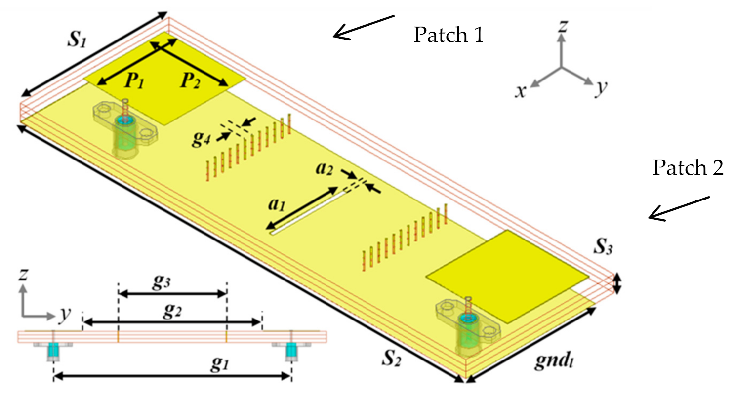
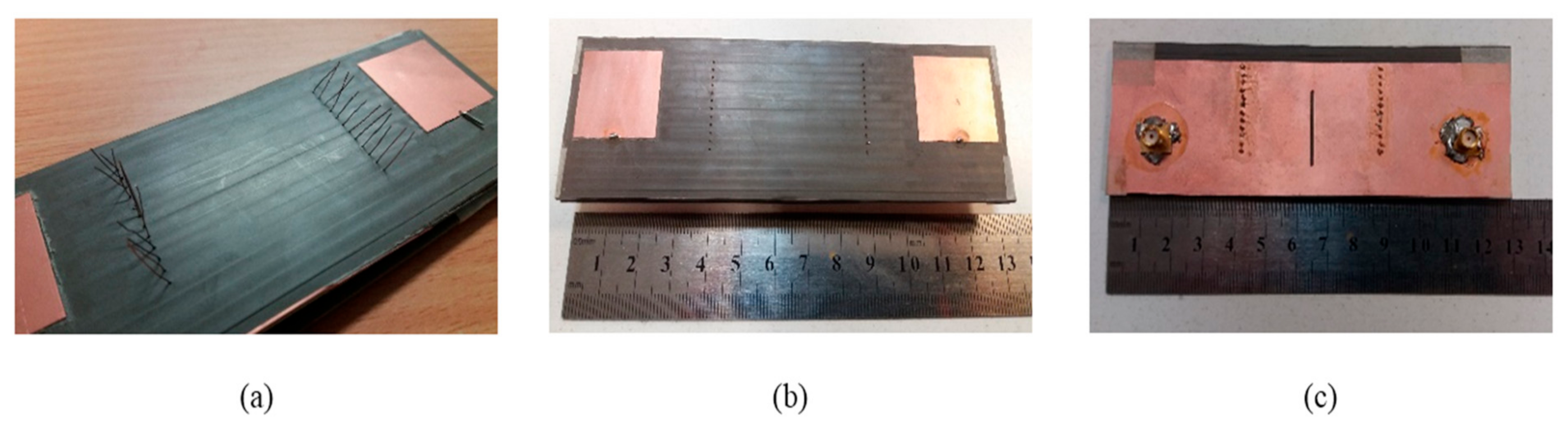
2. Antenna Design
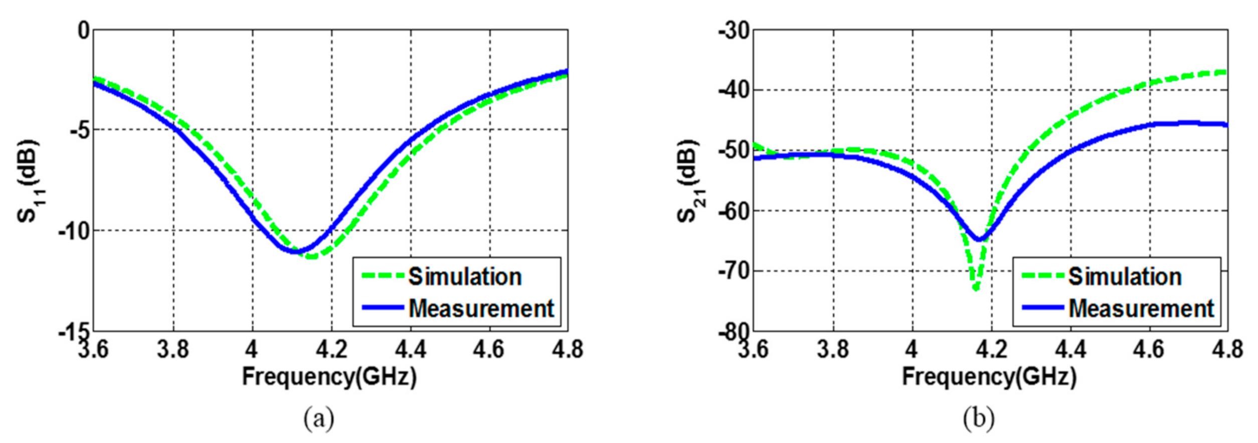
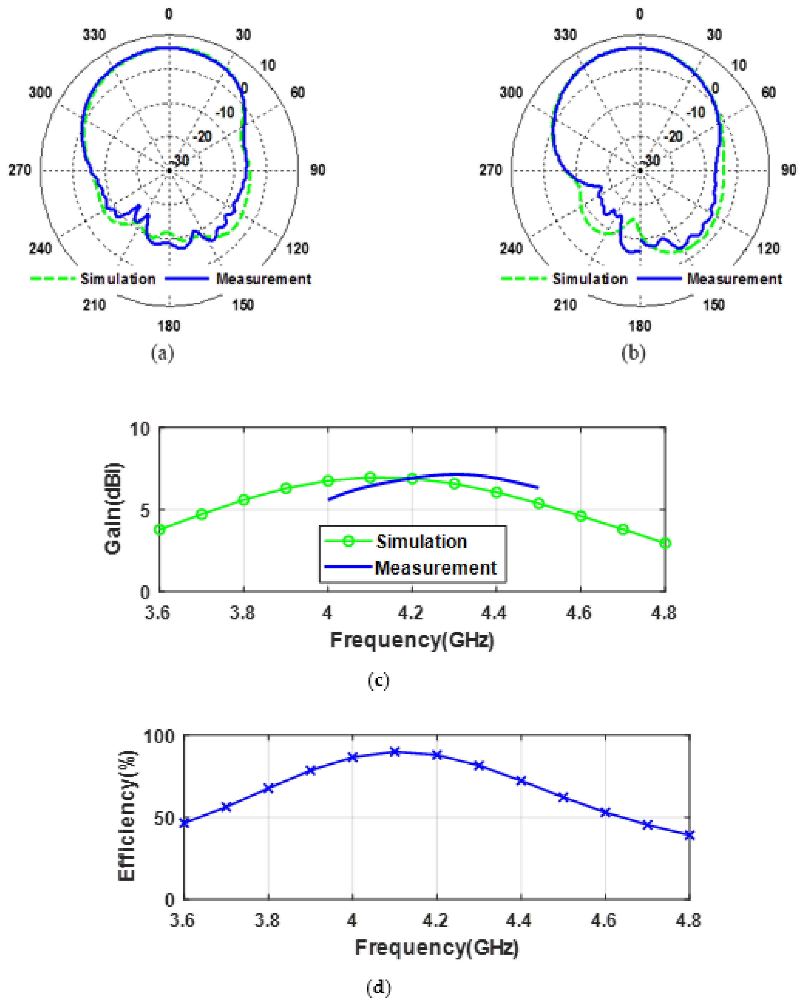
3. Results
4. Comparison
5. Conclusions
Author Contributions
Funding
Conflicts of Interest
References
- Nebylov, A.V. Aerospace Sensors, 1st ed.; Momentum Press: New York, NY, USA, 2013; p. 348. [Google Scholar]
- ITU Radio Regulations. Operation and Technical Characteristics and Protection Criteria of Radio Altimeters Utilizing the Band 4200–4400 MHz. 2014. Available online: https://www.itu.int/pub/R-REG-RR (accessed on 22 December 2020).
- Kayton, M.; Fried, W.R. Avionics Navigation Systems, 2nd ed.; John Wiley & Sons, Inc.: New York, NY, USA, 1997; 773p. [Google Scholar]
- Robin, S.; Klein, Y. Laterally Isolated Microstrip Antenna. US Patent 4,460,894 45, 17 July 1984. [Google Scholar]
- Luan, H.; Chen, C.; Chen, W.; Zhou, L.; Zhang, H.; Zhang, Z. Mutual Coupling Reduction of Closely E/H-Plane Coupled Antennas Through Metasurfaces. IEEE Antennas Wirel. Propag. Lett. 2019, 18, 1996–2000. [Google Scholar] [CrossRef]
- Skolnik, M.I. Radar Handbook, 3rd ed.; McGraw-Hill Education: New York, NY, USA, 2008. [Google Scholar]
- Vidmar, M. Design Improves 4.3-GHz Radio Altimeter Accuracy. Microw. Rf J. 2005. Available online: https://www.semanticscholar.org/paper/Design-improves-4.3-GHz-radio-altimeter-accuracy-Vidmar/abfc7c1dd383aa9e584508150a074d0475b8bcff (accessed on 22 December 2020).
- Leo, G. Maloratsky “Single Antenna FM Radio Altimeter Operating in a Continuous Wave Mode and an Interrupted Continuous Wave Mode. U.S. Patent 6,426,717, 30 July 2002. [Google Scholar]
- Zhang, S.; Pedersen, G.F. Mutual Coupling Reduction for UWB MIMO Antennas with a Wideband Neutralization Line. IEEE Antennas Wirel. Propag. Lett. 2015, 15, 166–169. [Google Scholar] [CrossRef]
- Habashi, A.; Nourinia, J.; Ghobadi, C. Mutual Coupling reduction between very closely spaced patch antennas using low-profile folded split ring resonators. IEEE Antennas Wirel. Propag. Lett. 2011, 10, 862–865. [Google Scholar] [CrossRef]
- Farsi, S.; Aliakbarian, H.; Schreurs, D.; Nauwelaers, B.; Vandenbosch, G.A.E. Mutual Coupling Reduction between Planar antennas by using a simple Microstrip U-section. IEEE Antennas Wirel. Propag. Lett. 2012, 11, 1501–1503. [Google Scholar] [CrossRef]
- Li, Q.; Feresidis, A.P.; Mavridou, M.; Hall, P.S. Miniaturized double-layer EBG structures for broadband mutual coupling reduction between UWB monopoles. IEEE Trans. Antennas Propag. 2015, 63, 1168–1171. [Google Scholar] [CrossRef]
- Alsath, M.G.N.; Kanagasabai, M.; Balasubramanian, B. Implementation of slotted meander-line resonators for isolation enhancement in microstrip patch antenna arrays. IEEE Antennas Wirel. Propag. Lett. 2013, 12, 15–18. [Google Scholar] [CrossRef]
- Assimonis, S.D.; Yioultsis, Y.V.; Antonopoulos, C.S. Design and Optimization of Uniplanar EBG Structures for Low Profile Antenna Applications and Mutual Coupling Reduction. IEEE Trans. Antennas Propag. 2012, 60, 4944–4949. [Google Scholar] [CrossRef]
- Arun, H.; Sarma, A.K.; Kanagasabai, M.; Velan, S.; Raviteja, C.; Alsath, M.G.N. Deployment of Modified Serpentine for Mutual Coupling Reduction in MIMO Antennas. IEEE Antenna Wirel. Propag. Lett. 2014, 13, 277–280. [Google Scholar] [CrossRef]
- Ntaikos, D.K.; Yioultsis, Y.V. Compact split-ring resonator-loaded multiple-input–multiple-output antenna with electrically small elements and reduced mutual coupling. IET Microw. Antennas Propag. 2013, 7, 421–429. [Google Scholar] [CrossRef]
- Farahani, M.; Pourahmadazar, J.; Akbari, M.; Nedil, M.; Sebak, A.R.; Denidni, T.A. Mutual Coupling Reduction in Millimeter-Wave MIMO Antenna Array Using a Metamaterial Polarization-Rotator Wall. IEEE Antennas Wirel. Propag. Lett. 2017, 16, 2324–2327. [Google Scholar] [CrossRef]
- Qamar, Z.; Naeem, U.; Khan, A.S.; Chongcheawchamnan, M.; Shafique, M.F. Mutual Coupling Reduction for High Performance Densely Packed Patch Antenna Arrays on Finite Substrate. IEEE Trans. Antennas Propag. 2016, 64, 1653–1660. [Google Scholar] [CrossRef]
- Bait-Suwailam, M.M.; Siddiqui, O.F.; Ramahi, O.M. Mutual Coupling Reduction between Microstrip Patch antennas using slotted complementary Split-Ring Resonators. IEEE Antennas Wirel. Propag. Lett. 2010, 9, 876–878. [Google Scholar] [CrossRef]
- Qi, H.; Yin, X.; Zhao, H.; Kulseza, W.J. Mutual Coupling Suppression between Two Closely Spaced Microstrip Antennas with an Asymmetrical Coplanar Strip Wall. IEEE Antennas Wirel. Propag. Lett. 2015, 15, 191–194. [Google Scholar] [CrossRef]
- Park, C.H.; Son, H.W. Mutual coupling reduction between closely spaced micro-strip antennas by means of H-shaped conducting wall. IET Electron. Lett. 2016, 52, 1093–1094. [Google Scholar] [CrossRef]
- Nadeem, I.; Choi, D. Study on Mutual Coupling Reduction Technique for MIMO Antennas. IEEE Access 2019, 7, 563–586. [Google Scholar] [CrossRef]
- Thomas, S.H.; Reilly, T.J.; Backes, G.B. High Accuracy Radar Altimeter Using Automatic Calibration. U.S. Patent 8,044,842, 25 October 2011. [Google Scholar]
- Maloratsky, L.G. An aircraft single-antenna FM radio altimeter. Microw. J. 2003, 46, 196–210. [Google Scholar]
- Vishvaksenan, K.S.; Mithra, K.; Kalaiarasan, R.; Raj, K.S. Mutual Coupling Reduction in Microstrip Patch Antenna Arrays Using Parallel Coupled-Line Resonators. IEEE Antennas Wirel. Propag. Lett. 2017, 16, 2146–2149. [Google Scholar] [CrossRef]


| Parameter | S1 | S2 | S3 | P1 | P2 | gndl |
|---|---|---|---|---|---|---|
| Length (mm) | 42.8 | 128.4 | 4.71 | 23.55 | 23.55 | 37.48 |
| Parameter | g1 | g2 | g3 | g4 | a1 | a2 |
| Length (mm) | 99 | 75.48 | 45.07 | 2.14 | 21.41 | 1.07 |
| Reference | Decoupling Technique | Mutual Coupling Level w/o Decoupling Technique (Mw/o) | Mutual Coupling Level w/ Decoupling Technique (Mw) | Improvement in |S21| (Mw-Mw/o) |
|---|---|---|---|---|
| [9] | Neutralization Line | −11 | −33 | 22 dB |
| [11] | U-shape Microstrip | −22 | −38 | 16 dB |
| [12] | Double Layer EBG Structure | −10 | −37 | 27 dB |
| [13] | Slotted Meander Line Resonator | −16 | −32 | 16dB |
| [14] | Uni-planar EBG Structure | −30 | −55 | 25 dB |
| [17] | Using Metamaterial Polarization Rotator | −28 | −50 | 22 dB |
| [18] | Metamaterial based Decoupling Slab | −25 | −52 | 27 dB |
| [19] | Slotted Split Ring Resonators | −18 | −28 | 10 dB |
| [25] | Coupled Line Resonator | −13.8 | −40 | 26.2 dB |
| This work | MGS | −37 | −65 | 28 dB |
Publisher’s Note: MDPI stays neutral with regard to jurisdictional claims in published maps and institutional affiliations. |
© 2020 by the authors. Licensee MDPI, Basel, Switzerland. This article is an open access article distributed under the terms and conditions of the Creative Commons Attribution (CC BY) license (http://creativecommons.org/licenses/by/4.0/).
Share and Cite
Sadiq, M.S.; Ruan, C.; Nawaz, H.; Abbasi, M.A.B.; Nikolaou, S. Mutual Coupling Reduction between Finite Spaced Planar Antenna Elements Using Modified Ground Structure. Electronics 2021, 10, 19. https://doi.org/10.3390/electronics10010019
Sadiq MS, Ruan C, Nawaz H, Abbasi MAB, Nikolaou S. Mutual Coupling Reduction between Finite Spaced Planar Antenna Elements Using Modified Ground Structure. Electronics. 2021; 10(1):19. https://doi.org/10.3390/electronics10010019
Chicago/Turabian StyleSadiq, Muhammad Shahzad, Cunjun Ruan, Hamza Nawaz, M. Ali Babar Abbasi, and Symeon Nikolaou. 2021. "Mutual Coupling Reduction between Finite Spaced Planar Antenna Elements Using Modified Ground Structure" Electronics 10, no. 1: 19. https://doi.org/10.3390/electronics10010019
APA StyleSadiq, M. S., Ruan, C., Nawaz, H., Abbasi, M. A. B., & Nikolaou, S. (2021). Mutual Coupling Reduction between Finite Spaced Planar Antenna Elements Using Modified Ground Structure. Electronics, 10(1), 19. https://doi.org/10.3390/electronics10010019