Article

Dual-Polarized Dual-Loop Double-Slot Antipodal Tapered Slot Antenna for Ultra-Wideband Radar Applications

1
Aerospace Information Research Institute, Chinese Academy of Sciences, Beijing 100190, China
2
School of Electronic, Electrical and Communication Engineering, University of Chinese Academy of Sciences, Beijing 100049, China
*
Author to whom correspondence should be addressed.
Electronics 2021, 10(12), 1377; https://doi.org/10.3390/electronics10121377
Submission received: 10 May 2021 / Revised: 2 June 2021 / Accepted: 6 June 2021 / Published: 8 June 2021
(This article belongs to the Section Microwave and Wireless Communications)

Abstract

:
The miniaturized high-gain antenna is required in portable, ultra-wideband radar systems. However, the miniaturization, ultra-wideband and high gain often restrict each other in the antenna design. In this paper, a dual-polarized, double-slot, antipodal tapered slot antenna with a double-layer, dual-loop structure and novel slot edges is presented. The proposed magnetic dual-loop structure has the capacity to reduce the low cut-off frequency of the double-slot tapered slot antenna by weakening the resonance and coupling. In addition, the high gain, low sidelobe level (SLL), and low cross-polarization level are achieved in the boresight direction. A novel gradient slot profile is designed to improve the low-frequency directivity of the tapered slot antenna without affecting the matching. To feed the antenna elements, a kind of wideband, balun-divider structure is designed. The dual-polarized antenna is combined by two orthogonal elements in a cross configuration without galvanic contact or influence to performance. The measured results show that the impedance bandwidth of the proposed antenna is 0.6~4 GHz, and the maximum gain is 11 dBi. The isolation between the two antenna ports is better than 32 dB, and the cross-polarization discrimination (XPD) is better than 20 dB.

1. Introduction

Recently, dual-polarized antennas have been increasingly in demand and deeply studied in ultra-wideband (UWB) systems, such as radar, wireless communication, and microwave imaging systems [1]. Through-the-wall radar (TWR) is a kind of radar that can extract the polarization features of the human body echo and recognize its postures by using dual-polarized antennas [2]. To realize a wideband, directive, dual-polarized antenna, two elements with linear polarization are traditionally orientated into a cross shape [3]. However, miniaturization and radiation enhancement are still challenging in practical applications [4]. As a kind of travelling-wave antennas, the tapered slot antenna (TSA) is widely used to form dual-polarized TSAs owing to its advantages of low cost and low weight [5]. However, it has disadvantages of lowest frequency limitation and radiation pattern distortion at high frequencies. In particular, the conventional antipodal TSAs (ATSAs) suffer from the skew of E-field that result in poor cross polarization and beam tilt [6]. Though the UWB feeding transition of ATSA brings a wider bandwidth, it enlarges the total profile [7]. To improve the directivity, a double-slot structure was proposed by Wang et al. [8]. Many efforts have been made to develop the structure since then [9,10,11,12,13]. However, the existing research only focuses on high-frequency performance, ignoring the large size of this structure. For TSAs that are uniplanar or antipodal, single-slot or double-slot, orthogonal design without galvanic contact and polarization interference remains an important research field [14,15,16,17,18,19,20].
In this paper, a modified dual-polarized double-slot ATSA is designed. The dual-loop structure, as well as Fibonacci slot edges (FSEs), are applied to form a symmetric structure to improve the antenna performance. A compact balun-divider structure is proposed to minimize the total length. Simulated and measured results both show that the lowest frequency is greatly reduced, and the high gain is maintained. By a smart design of the double-layer structure, the elements are easy to be integrated. The elements of the integrated dual-polarized antenna keep good performance. The loss materials, such as brick, concrete, and wood, can be penetrated by the low-frequency electromagnetic waves with less energy loss. Thus, the proposed miniaturized antenna is suitable for portable TWR systems. This paper is organized as follows: In Section 2, the geometric structure, radiation mechanism, and feeding structure of the antenna are presented. The simulation and measured results of the antenna properties are shown in Section 3. In Section 4, the superior performance of the proposed antenna is verified by a comparison. Finally, Section 5 draws the conclusion.

2. Antenna Geometry and Design

The configuration of the proposed dual-polarized double-slot ATSA (DP-DSATSA) is shown in Figure 1a. The DP-DSATSA is composed of two double-slot antenna elements, which are placed in a cross shape. It is clear that the two-sided metal with rotational symmetry about the Y-axis avoids the electrical contact of the two elements. The copper on the top layer is indicated in red while the copper on the bottom layer is blue. Port 1 and Port 2 are located on the opposite side of the radiating structure, feeding the double-slot structures of Element 1 and Element 2 by double-sided parallel strip lines (DSPSL). The details of the two double-slot antenna elements are shown in Figure 1b,c. The two elements have different feed lines and board cutting.

2.1. Radiating Structure

The configuration of a conventional ATSA, shown in Figure 2a, is used as a starting point for the design, and the evolutionary steps are illustrated in Figure 2b–e. The surface current at 1 GHz is also shown in each structure, which reveals the specific operating mechanism. The current distributions in all five figures are of the same phase and normalized to the maximum value, respectively. The substrate used for all designs is made of Rogers 4350B with a relative permittivity of 3.48 and a loss tangent of 0.004. The thickness of the substrate is chosen as 0.762 mm. The conventional ATSA in Figure 2a, which is fed by DSPSL, has a multiple-octave bandwidth but it is limited by the main beam squint, beam split, and low directivity. Moreover, to improve the matching at a low frequency, the outer edges need to be cut into rounded corners, but the gain will be further reduced. TSAs with a double-slot structure have been proposed recently to generate near-field quasi-plane waves. According to the state-of-the-art design theory, the two in-phase wavefronts merge into one at the aperture [12]. The direction of the electric field is parallel to the substrate, perpendicular to the direction of propagation. Hence, the structure shown in Figure 2b is similar to an array formed by two electric dipoles. However, the asymmetric radiating arms of the double-slot antipodal tapered slot antenna (DSATSA) result in a strong coupling current between the two short arms and deterioration of low-frequency characteristics. These shortcomings are inherent and cannot be solved by optimization. Apart from the poor return loss in Figure 3a, the impact is also obvious as the two local minima on the gain curve and the two local maxima on the XPD curve, shown by the red short-dashed line in Figure 3b. As they are used to form a dual-polarized antenna, the antenna elements show further poorer performance because of the coupling current.
In this paper, we focus on the optimization of the resonance structure and weakening of the coupling current. After simply applying an extended loop structure to the short arm as shown in Figure 2c, the current on the inner edge of the short arm (E4 in Figure 1b) cannot form a travelling wave. However, the coupling current is still strong. The two resonance points in Figure 3b move down to the lower frequencies as shown by the blue dashed line.
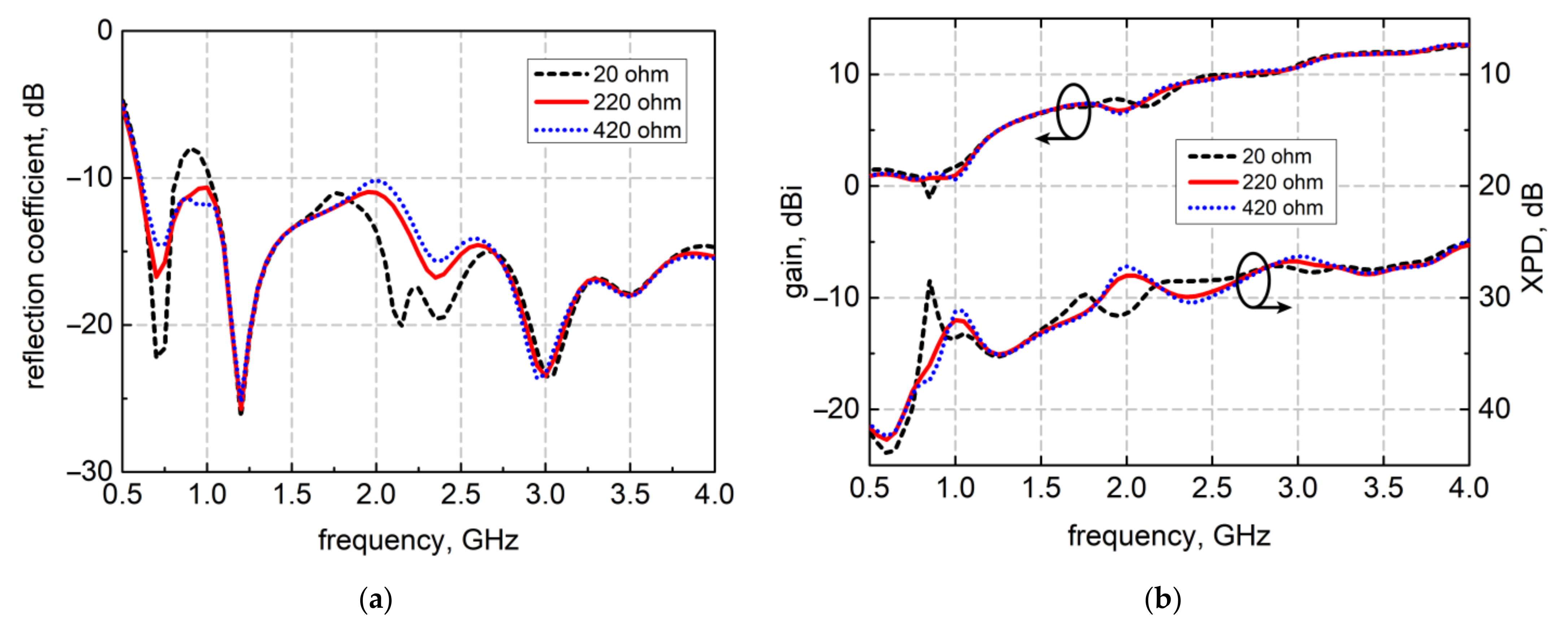
By adding the resistors to the end of short arms, the current distribution on the inner and outer edges is changed. Figure 4 shows how the resistance value affects the resonance level of the Dual-loop DSATSA. When the resistance value is small, the effect of loading is not obvious, and the resonance is not improved. As the resistance increases, the loop current at inner edges is formed. Thus, the reflections occurring at inner edges are significantly reduced. Considering both the reflection coefficient and radiation characteristics, the resistance value is chosen as 220 Ω. Then the novel radiating part presented in Figure 2d becomes a hybrid magnetoelectric structure. The two slots act as two electric dipoles, while the short arms are modified into two in-phase magnetic rings. The corresponding results are shown in Figure 3a,b with pink dash–dot lines. By removing the two sudden changes in the frequency domain, the cross-polarization of DSATSA is improved and the forward gain steadily increases without reducing efficiency. The geometry was optimized using Ansys HFSS, and the equations for edges E1E4, referring to Figure 1b, and the related ranges of x are defined as follows:
E 1 :   y x = 0.08 · log 10 2 · x 0.15 + 1 0 x W 1 + W f d / 2 2 1
E 2 :   y x = 0.02 · log 10 2 · x 0.02 + 1 0 x W 1 W f d / 2 2
E 3 :   y x = 0.04 · log 10 2 · x 0.01 + 1 0 x W 2 + W f d / 2 2 5 R 1 3
E 4 :   y x = 0.03 · log 10 2 · x 0.1 + 1 0 x W 2 W f d / 2 2 3 R 2 2
The variables x and y correspond to the coordinate axis in Figure 1c. As shown in Figure 1c, the variable W1 represents the width of the long arm, while the variable W2 means the width of the short arm. R1 and R2 represent the two arc radii on the short arm. Meanwhile, the variable Wfd is shown is Figure 5, meaning the line width of the DSPSL.
In order to enhance the radiation of the dual-loop DSATSA at low frequency, a novel Fibonacci slot profile is proposed in this paper. As shown in Figure 3b, the deterioration of the co-polarized gain is accompanied by the increase in cross polarization. By adding slots to the long arms, which are shown in Figure 2e, more surface current is excited at or above 1 GHz. The longest slots work like additional active structures and enhance the radiation of the tapered slot, resulting in improvement of the directivity. The minimal reflection is achieved by the 45° inclined slots with a gradient length variation. The key active slot is related to the electrical length, so the shorter slots are activated at high frequency. The FSEs are made up of a series of grooves whose lengths Lse are successively increased according to Fibonacci numbers (1, 1, 2, 3, 5, 8, 13, 21, 34). The numbers are generated by a recursive formula:
X n = X n 1 + X n 2   X 0 = X 1 = 1 ,   2 n 8
X n = X 17 n   9 n 17
After the peak value, the groove length is reduced according to the mirror image of the above series. The horizontal length of the slot edge Lse can be calculated by the following:
L s e n = X n · 1   mm
The inclined slots will show different profiles when the groove length increases and decreases. From the results of green solid lines in Figure 3, this design does not affect the characteristics at other frequencies. The gain and XPD at around 1 GHz are greatly improved.

2.2. Feeding Structure

The balun-divider structure is designed to output two signals with equal amplitude and phase to excite the double-slot radiating structure. A shortened CPW-DSPSL transition is proposed to realize the transformation from unbalanced mode to balanced mode. The characteristic impedance of 50 Ω is unchanged in this transition. The central strip of CPW is converted to the bottom layer, and the ground planes on both sides are combined together on the top layer. The T-junction power divider placed behind the balun is modeled based on DSPSL, as shown in Figure 5. The output impedance Z02 and Z03 of this low-loss divider can be jointly determined by the input impedance Z01 and the formula as follows:
Z 01 = 1 Z 02 + 1 Z 03 1 = Z 02 · Z 03 Z 02 + Z 03
The calculated output impedance, which is also the impedance of DSPSL and the input impedance of double-slot ATSA, is 100 Ω. To complete the structure of the dual-polarized antenna, the novel radiating structure proposed in this paper is symmetrical, and a couple of complementary slots can be cut in the center of the substrate. Meanwhile, the feeding structures need to be offset from the center to avoid affecting the slotting. The layout of the DSPSL is specifically designed to ensure equal input signals, as shown in Figure 5.
Figure 6a shows that the S11 of the input port is less than −20.5 dB from 0.5 to 4 GHz, while the insertion losses from the input ports to output ports are both less than 0.8 dB. The proposed feeding structure has excellent S-parameters among the ultra-wideband, ensuring a minimal insertion loss. To form a symmetric beam at the boresight direction, the amplitude imbalance and phase imbalance between the output ports are vital indexes in the design of the divider, affecting the boresight beam symmetry. The simulated results are presented in Figure 6b. The differences in amplitude and phase fluctuate around zero in the frequency domain, which are 0.3 dB and 1.5 deg, respectively. The dimensions of the radiation part and feeding structures are shown in Table 1. By integrating the radiation structure and balun-divider structure, two complete dual-loop loaded DSATSA elements can be obtained, as shown in Figure 1b,c. The dual-polarized antenna can be formed by integrating the two elements together.

3. Results

On the left part of Figure 7, a fabricated prototype of the DP-DSATSA is presented. The welding details of resistor and coaxial joint are displayed. From the back view at the center of Figure 7, the two feeding ports and crossed feeding circuits are shown clearly. The reflection coefficients of the two feeding ports are measured, using a vector network analyzer named Keysight E5063A. The far-field characteristics are measured in a microwave anechoic chamber, which is shown on the right part of Figure 7.
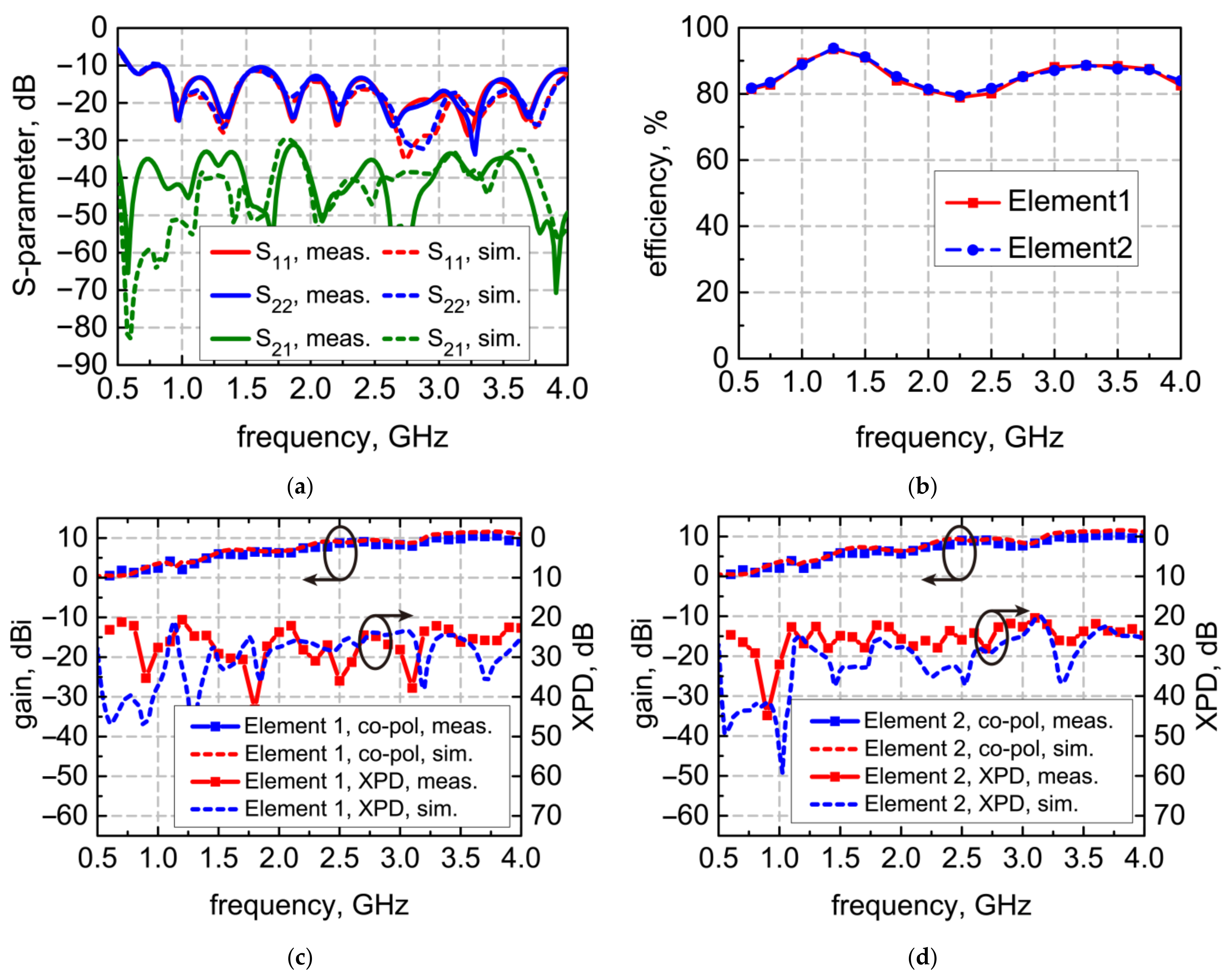
The DSATSA elements measured as parts of dual-polarized antenna both have impedance bandwidths from 0.6 GHz to 4 GHz with S11 less than −10 dB, as displayed in Figure 8a. The simulated and the measured mutual coupling results (S21) between the two ports are lower than −30 and −32 dB, respectively. The simulated efficiency of the antenna with Port 1 or Port 2 excited separately is shown in Figure 8b. The efficiency of each element is higher than 80% through the whole band.
In Figure 8c,d, the simulated and the measured far-field characteristics for both elements are shown at different frequencies up to 4 GHz. The measured gain at boresight is between 1 and 11 dBi, which is almost the same as the simulated results. The measured XPD results in the direction of the boresight coincide well with the simulated ones. In the operating band, the XPD is higher than 20 dB. The small differences between the numerical results and measured results are mainly caused by manufacturing inaccuracies, including inaccuracies in the printed circuit board manufacturing and welding.
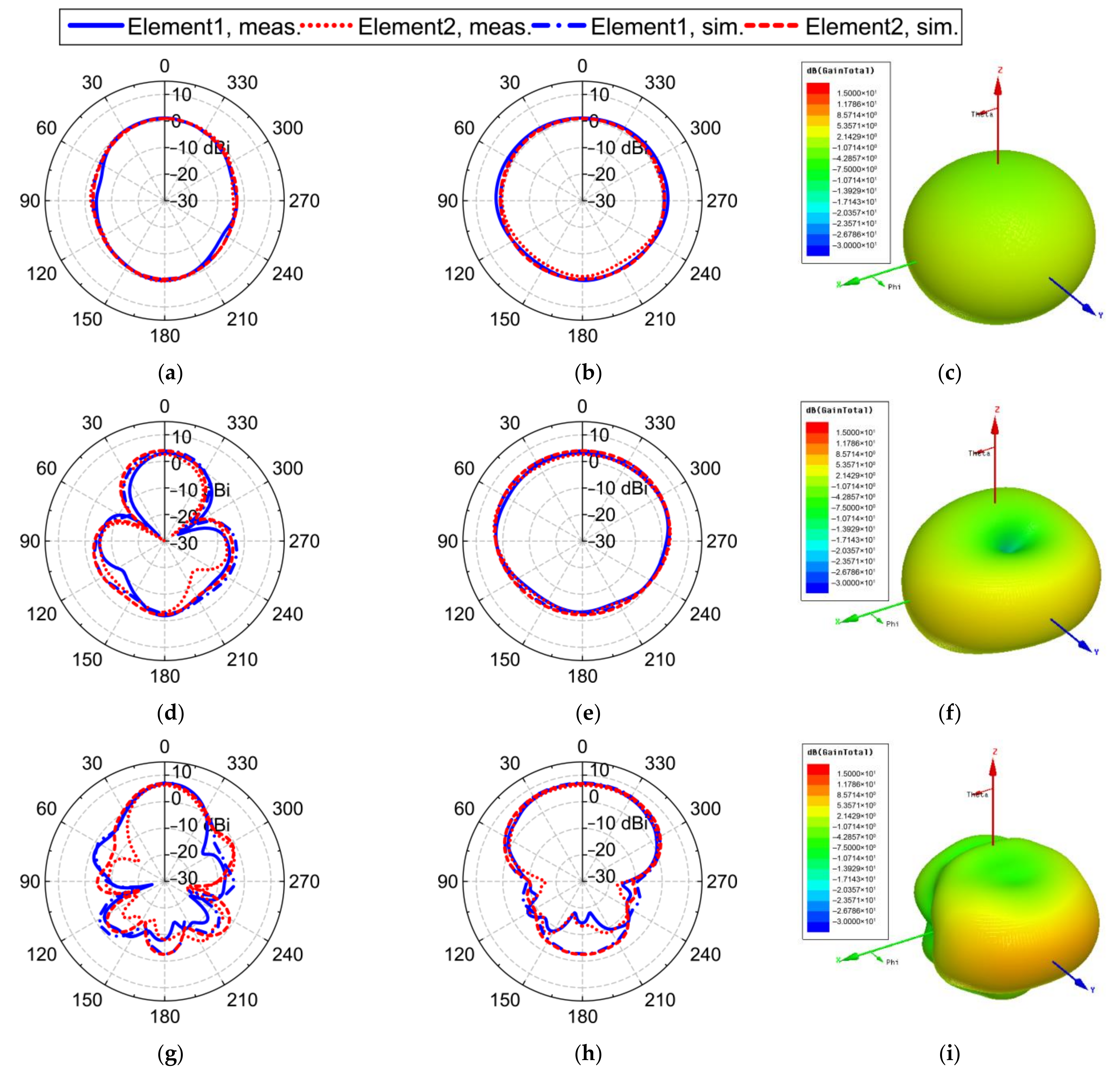
Figure 9 displays the simulated and measured radiation patterns of the proposed elements at 0.6, 1, 2, and 4 GHz. The results include 2D and 3D patterns. The 2D patterns show the detailed comparison between the simulated and measured results. In the rightmost column of Figure 9, simulated 3D patterns of Element 1 are shown since the two elements have similar radiating characteristics. It can be observed that the radiation patterns of the proposed DSATSA at frequencies below 1 GHz are similar to the results of an omnidirectional antenna, though the E-plane beamwidth is a little narrower than the H-plane. The reason for this phenomenon is that the double slots radiate like two finite dipoles. However, due to the FSEs, the radiating performance of the novel DSATSA at around 1 GHz is improved. Meanwhile, it still shows remarkable radiation characteristics of low SLL, narrow beamwidth in E-plane, and symmetric patterns at high frequencies above 1 GHz.

4. Discussion

A comparison of the characteristics with dual-polarized antenna designs using ATSAs reported in the literature is given in Table 2. The low cut-off frequency achieved by the design proposed in this paper appears to be lower than that in reference [14,15,16,17,18,19]. The length of the radiating structure is only 190 mm. After adding the feeding structure, the total length and width of the proposed antenna element are 220 mm, corresponding to 0.44 times the longest operating wavelength of 50 cm. Meanwhile, the highest port isolation and XPD are realized by the novel design accompanied by a relatively high gain. It is worth mentioning that the antenna elements of dual-polarized TSAs in the literature usually have different characteristics, especially for another DP-DSATSA, such as [18]. In the proposed design, the performance of the two elements is nearly the same. For the lens-loaded tapered slot antenna used for TWR [19], the gain of the single-slot structure is enhanced but the XPD and port isolation are low. For the miniaturized, single-slot, tapered slot antenna proposed in [20], the peak gain, XPD, and port isolation are lower than the proposed antenna.
With a relatively low profile, the proposed antenna achieves high-efficiency radiation at low frequencies and high gain characteristics at high frequencies. Due to the miniaturized profile, the peak gain of the proposed tapered slot structure can be further improved by adding a lens. Thus, it has obvious advantages in the application of penetrating detection systems or communication systems. The dual-polarized configuration can be used for analyzing the polarization features of the target echo or polarization diversity.

5. Conclusions

This paper proposes a novel dual-loop double-slot structure used for the dual-polarized antipodal tapered slot antenna that operates between 0.6 and 4 GHz. The antenna implements a hybrid magnetoelectric structure and new Fibonacci slot edges to overcome the shortcomings of ATSA and DSATSA in terms of asymmetric radiation patterns, low gains, and large profiles. Through numerical simulations of evolutionarily progressive structural modifications, the radiation mechanisms are revealed. A low-loss balun-divider structure is also proposed to feed the combined dual-polarized antenna. The experimental measurements demonstrate the superiority of the proposed DP-DSATSA and validate its design. Since this paper focuses on the improvement of the basic radiating structure, the performance can be further enhanced by inserting a parasitic structure, such as a metalens. Dual-polarized antennas can obtain more information of the target. It is feasible to make image fusion and polarization classification of the human body through polarization information. Thus, the antenna has good application prospects in the field of penetrating detection and human posture recognition.

Author Contributions

Conceptualization, G.Y. and S.Y.; methodology, G.Y. and F.Z.; software, G.Y.; validation, G.Y., S.Y. and F.Z.; formal analysis, G.Y.; investigation, G.Y. and Y.J.; resources, Y.J.; data curation, G.Y.; writing—original draft preparation, G.Y.; writing—review and editing, S.Y. and X.Z.; visualization, G.Y.; supervision, G.F.; project administration, X.Z.; funding acquisition, G.F. All authors have read and agreed to the published version of the manuscript.

Funding

This research was funded by the National Key Research and Development Plan, grant number 2018YFC0810200, ZH, grant number 30201, and National Natural Science Foundation, grant number 61827803.

Conflicts of Interest

The authors declare no conflict of interest.

References

  1. Wang, X.-Y.; Tang, S.-C.; Yang, L.-L.; Chen, J.-X. Differential-Fed Dual-Polarized Dielectric Patch Antenna with Gain Enhancement Based on Higher Order Modes. IEEE Antennas Wirel. Propag. Lett. 2020, 19, 502–506. [Google Scholar] [CrossRef]
  2. Park, J.; Johnson, J.T.; Majurec, N.; Frankford, M.; Stewart, K.; Smith, G.E.; Westbrook, L. Simulation and analysis of polarimetric radar signatures of human gaits. IEEE Trans. Aerosp. Electron. Syst. 2014, 50, 2164–2175. [Google Scholar] [CrossRef]
  3. Li, M.; Li, Q.L.; Wang, B.; Zhou, C.F.; Cheung, S.W. A Low-Profile Dual-Polarized Dipole Antenna Using Wideband AMC Reflector. IEEE Trans. Antennas Propag. 2018, 66, 2610–2615. [Google Scholar] [CrossRef]
  4. Mirmozafari, M.; Zhang, G.; Fulton, C.J.; Doviak, R.J. Dual-Polarization Antennas with High Isolation and Polarization Purity: A Review and Comparison of Cross-Coupling Mechanisms. IEEE Antennas Propag. Mag. 2018, 61, 50–63. [Google Scholar] [CrossRef]
  5. Liu, Y.; Zhou, W.; Yang, S.; Li, W.; Li, P.; Yang, S. A Novel Miniaturized Vivaldi Antenna Using Tapered Slot Edge with Resonant Cavity Structure for Ultrawideband Applications. IEEE Antennas Wirel. Propag. Lett. 2016, 15, 1881–1884. [Google Scholar] [CrossRef]
  6. Wang, N.-N.; Fang, M.; Chou, H.-T.; Qi, J.-R.; Xiao, L.-Y. Balanced Antipodal Vivaldi Antenna with Asymmetric Substrate Cutout and Dual-Scale Slotted Edges for Ultrawideband Operation at Millimeter-Wave Frequencies. IEEE Trans. Antennas Propag. 2018, 66, 3724–3729. [Google Scholar] [CrossRef]
  7. Li, X.; Zhou, H.; Gao, Z.; Wang, H.; Lv, G. Metamaterial Slabs Covered UWB Antipodal Vivaldi Antenna. IEEE Antennas Wirel. Propag. Lett. 2017, 16, 2943–2946. [Google Scholar] [CrossRef]
  8. Wang, Y.; Wang, G.; Gao, X.; Zhou, C. Double-slot Vivaldi antenna with improved gain. Electron. Lett. 2013, 49, 1119–1121. [Google Scholar] [CrossRef] [Green Version]
  9. So, Y.; Kim, W.; Kim, J.; Yong, Y.J.; Park, J. Double-slot antipodal Vivaldi antenna for improved directivity and radiation patterns. In Proceedings of the 2016 International Symposium on Antennas and Propagation (ISAP), Okinawa, Japan, 24–28 October 2016; pp. 382–383. [Google Scholar]
  10. Wang, Y.-W.; Yu, Z.-W. A Novel Symmetric Double-Slot Structure for Antipodal Vivaldi Antenna to Lower Cross-Polarization Level. IEEE Trans. Antennas Propag. 2017, 65, 5599–5604. [Google Scholar] [CrossRef]
  11. Malakooti, S.-A.; Moosazadeh, M.; Ranasinghe, D.C.; Fumeaux, C. Antipodal Vivaldi Antenna for Sum and Difference Radiation Patterns With Reduced Grating Lobes. IEEE Antennas Wirel. Propag. Lett. 2017, 16, 3139–3142. [Google Scholar] [CrossRef]
  12. Zhang, Y.; Li, E.; Wang, C.; Guo, G. Radiation Enhanced Vivaldi Antenna With Double-Antipodal Structure. IEEE Antennas Wirel. Propag. Lett. 2016, 16, 561–564. [Google Scholar] [CrossRef]
  13. Zhu, S.; Liu, H.; Wen, P.; Du, L.; Zhou, J. A Miniaturized and High Gain Double-Slot Vivaldi Antenna Using Wideband Index-Near-Zero Metasurface. IEEE Access 2018, 6, 72015–72024. [Google Scholar] [CrossRef]
  14. Sonkki, M.; Sanchez-Escuderos, D.; Hovinen, V.; Salonen, E.T.; Ferrando-Bataller, M. Wideband Dual-Polarized Cross-Shaped Vivaldi Antenna. IEEE Trans. Antennas Propag. 2015, 63, 2813–2819. [Google Scholar] [CrossRef] [Green Version]
  15. Dzagbletey, P.A.; Shim, J.Y.; Jeong, J.Y.; Chung, J.-Y. Dual-polarized Vivaldi antenna with quarter-wave balun feeding. In Proceedings of the 2017 Asia-Pacific International Symposium on Electromagnetic Compatibility (APEMC), Seoul, Korea, 20–23 June 2017; pp. 108–110. [Google Scholar]
  16. Song, L.; Zhou, H. Wideband dual-polarized Vivaldi antenna with improved balun feed. Int. J. Microw. Wirel. Technol. 2018, 11, 41–52. [Google Scholar] [CrossRef]
  17. Chen, D.; Wang, K.; Zhu, W.; Wang, L.; Liu, Z.; Wang, T.; Gao, J.; Zhu, S. 2–40 GHz dual-band dual-polarised nested Vivaldi antenna. IET Microw. Antennas Propag. 2019, 13, 163–170. [Google Scholar] [CrossRef]
  18. Kim, W.; Park, J.; Park, H.; Yoon, Y.J. Radiation characteristics enhancement of dual-polarized antipodal Vivaldi antenna using double-slot structure. Microw. Opt. Technol. Lett. 2019, 62, 1245–1251. [Google Scholar] [CrossRef]
  19. Cicchetti, R.; Cicchetti, V.; Faraone, A.; Foged, L.; Testa, O. A Compact High-Gain Wideband Lens Vivaldi Antenna for Wireless Communications and Through-the-Wall Imaging. IEEE Trans. Antennas Propag. 2020, 69, 1. [Google Scholar] [CrossRef]
  20. Dzagbletey, P.A.; Shim, J.-Y.; Chung, J.-Y. Quarter-Wave Balun Fed Vivaldi Antenna Pair for V2X Communication Measurement. IEEE Trans. Antennas Propag. 2019, 67, 1957–1962. [Google Scholar] [CrossRef]
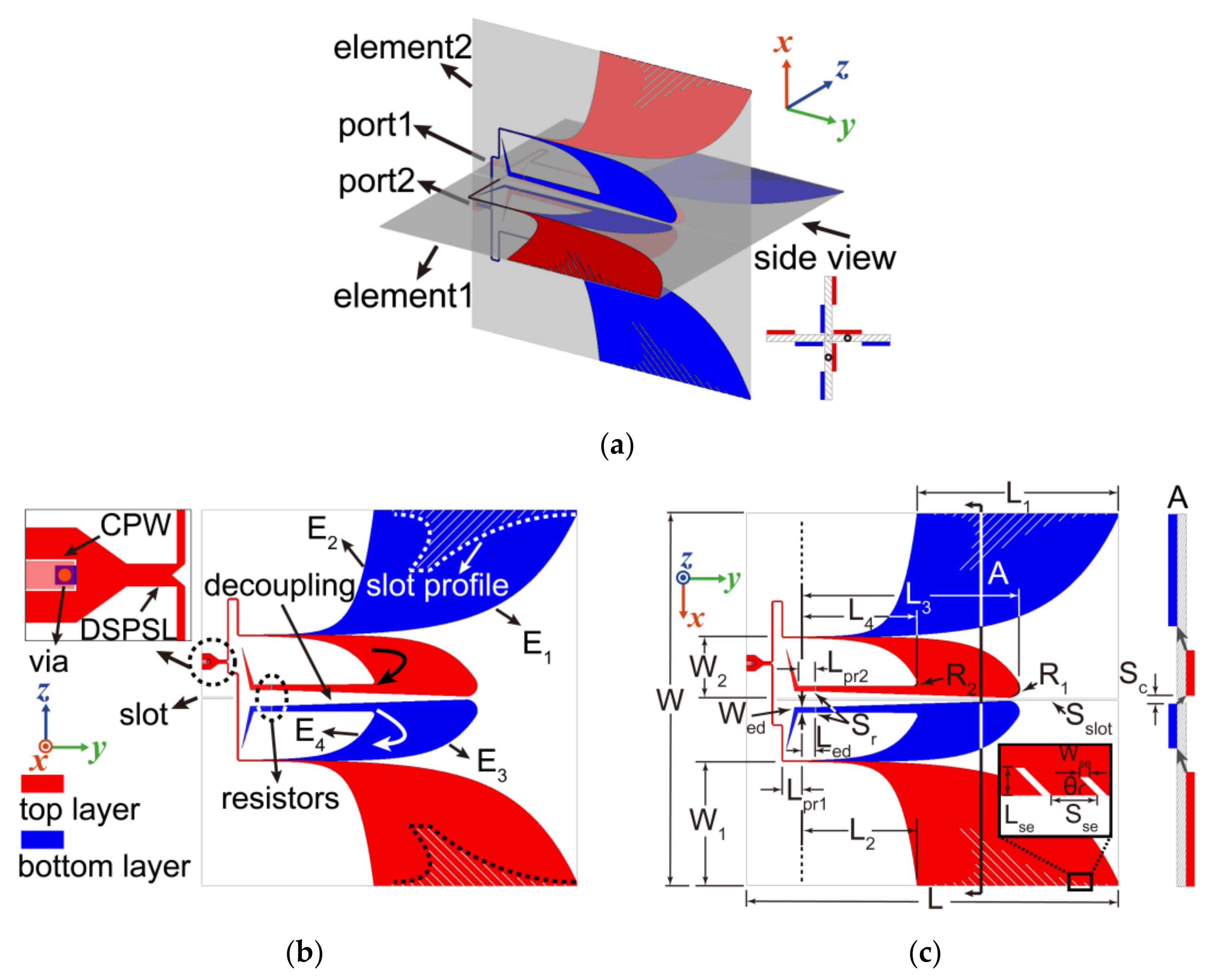
Figure 1. The structure of the proposed DP-DSATSA. (a) The total cross-shaped structure; (b) the main parts of Element 1; (c) the dimension diagram of Element 2.
Electronics 10 01377 g001
Figure 2. The surface current of ATSAs at 1 GHz and design evolution of radiating structure with the red part as the top metal layer, the blue part as the bottom metal layer, and the light gray part as the substrate. (a) The conventional ATSA; (b) the conventional DSATSA; (c) the dual-loop DSATSA without resistors; (d) the dual-loop DSATSA; (e) the dual-loop DSATSA with FSEs.
Electronics 10 01377 g002
Figure 3. Performance comparison of different types of antennas (1: Conventional ATSA; 2: Conventional DSATSA; 3: Dual-loop DSATSA without resistors; 4: Dual-loop DSATSA; 5: Dual-loop DSATSA with FSEs). (a) The reflection coefficient (S11); (b) the co-polarized gain and XPD at boresight.
Electronics 10 01377 g003
Figure 4. Performance comparison of Dual-loop DSATSA at different resistance values. (a) The reflection coefficient (S11); (b) the co-polarized gain and XPD at boresight.
Electronics 10 01377 g004
Figure 5. The configuration and dimension diagram of the balun-divider structures.
Electronics 10 01377 g005
Figure 6. The performance of the balun-divider structure. (a) The reflection coefficients of the input ports and insertion losses from input ports to output ports; (b) the amplitude imbalance and phase imbalance between the output ports.
Electronics 10 01377 g006
Figure 7. The fabricated dual-loop loaded DP-DSATSA and the test scene in the microwave anechoic chamber.
Electronics 10 01377 g007
Figure 8. The simulated and measured results of the proposed DP-DSATSA. (a) Measured and simulated S-parameters; (b) efficiency of elements in the DP-DSATSA; (c) measured and simulated gain of Element 1 in the DP-DSATSA; (d) measured and simulated gain of Element 2 in the DP-DSATSA.
Electronics 10 01377 g008
Figure 9. The simulated and measured gain patterns of the proposed elements in the DP-DSATSA. (a) E-plane patterns at 0.6 GHz; (b) H-plane patterns at 0.6 GHz; (c) 3D pattern at 0.6 GHz; (d) E-plane patterns at 1 GHz; (e) H-plane patterns at 1 GHz; (f) 3D pattern at 1 GHz; (g) E-plane patterns at 2 GHz; (h) H-plane patterns at 2 GHz; (i) 3D pattern at 2 GHz; (j) E-plane patterns at 4 GHz; (k) H-plane patterns at 4 GHz; (l) 3D pattern at 4 GHz.
Electronics 10 01377 g009aElectronics 10 01377 g009b
Table 1. The parameters of the proposed antenna.
Params.Value (mm)Params.Value (mm)Params.Value (mm)
L220Ls2202.5Wgnd9.45
L1120Lpr110Wtrans1.9
L270Lpr210Dvia1.3
L3130Lcpw5R16
L470Ltrans5R22
L537.54W220Sc2–9.6
L621.72W174.07Sr1
L721.72W235.43Sch0.82
L851.72Wed3Sld1.32
Lex5Wfd0.82Sse5
Led9Wpl2.25Swd2.25
Lpl5Wse1Scpw0.12
Ls117.5Wcpw2.75Sslot1
Table 2. The performance comparisons of the dual-polarized TSAs.
Ref.Relative
Bandwidth (%)
Element
Dimensions
(λL)
Peak
Gain
(dBi)
XPD
(dB)
Port
Isolation
(dB)
[14]158.20.55 × 0.5010.5≥20≥30
[15]1290.82 × 0.819.4≥18≥22.3
[16]550.81 × 0.673/≥15
[17]1201.62 × 0.8712≥20≥29.5
[18]100.11.80 × 0.5410≥18≥23
[19]160.90.65× 0.4815.8≥16.2≥17
[20]1730.35× 0.358.6≥17.2≥28
This work147.80.44 × 0.4411≥20≥32
Publisher’s Note: MDPI stays neutral with regard to jurisdictional claims in published maps and institutional affiliations.