Article

Prospective Powering Strategy Development for Intelligent-Tire Sensor Power Charger Application

by
C. Bambang Dwi Kuncoro
1,
Min-Feng Sung
2,
Cornelia Adristi
3,
Arvanida Feizal Permana
1 and
Yean-Der Kuan
1,*
1
Department of Refrigeration, Air Conditioning and Energy Engineering, National Chin-Yi University of Technology, Taichung 41170, Taiwan
2
Kenda Rubber Ind. Co. Ltd., Yuanlin Township, Changhua County 51064, Taiwan
3
Department of Electrical Engineering, Faculty of Engineering, Universitas Indonesia, Depok 16424, Indonesia
*
Author to whom correspondence should be addressed.
Electronics 2021, 10(12), 1424; https://doi.org/10.3390/electronics10121424
Submission received: 7 May 2021 / Revised: 10 June 2021 / Accepted: 11 June 2021 / Published: 14 June 2021

Abstract

:
Tire sensors embedded in a vehicle tire are stand-alone autonomous devices. A tire sensor reserve power strategy is crucial due to sensor energy sources limitations for long operational periods. This paper presents an innovative tire sensor powering strategy for the intelligent-tire system. The powering strategy offers a green concept, maintenance-free, and low-cost method in order to extend the tire sensor lifetime for long operating periods. The proposed strategy adopts wireless power transfer (WPT) technology to transfer power to an electrical load mounted on the rotational system without an interconnection cable. It is composed of a power transmitter designed to be mounted on the vehicle’s inner fender liner, and a power receiver that provides power to recharge the tire sensor battery/energy storage. The transmitter transfers power from the vehicle battery/accumulator to a power receiver coupled with the tire sensor which is mounted on the vehicle tire inner wall. WPT devices were designed based on induction electromagnetic coupling and can provide an output current up to 1A at 5 V. The proposed powering strategy was verified using a vehicle tire simulator model to emulate rotational motion. A voltage and current sensor module as well microcontroller and data logger modules were utilized as the load for the developed WPT system. The verification experimental and preliminary test results reveal that the proposed strategy can provide constant power to the load (in this case, the voltage is around 4.3 V and the current is around 21.1 mA) although the vehicle tire model was rotated at different speeds from 0 rpm to 800 rpm. The proposed system has the potential and feasibility for implementation in tire sensor power applications in the intelligent-tire system.

1. Introduction

Since the rapid development in advanced technology, nowadays, a modern vehicle is not only composed of a mechanical component like in the past. Various electronic sensors, microprocessors, software, communication network, and electronic control have been introduced in vehicle design and manufacturing [1,2]. Therefore, the modern vehicle offers many features regarding comfortability, safety, functionality, performance, and autonomy. Those features enhance the driving experience and passenger comfort. Among those features, a vehicle’s driver and passenger safety is one of the most important in vehicle driving systems.
Tires are vital vehicle parts that contribute a crucial role in ensuring vehicle safety and stability. Tire forces, inflation pressure, and contact friction coefficient are important tire parameters considered to achieve healthy tires. Healthy tires will be able to boost vehicle safety and driving comfort. The data reported that road accident fatalities are still high. It is estimated that 1.2 million fatalities occur per year worldwide [3]. Although tire conditions are not always the main cause of road accidents, healthy tires can contribute to reducing the high rate of road accident fatalities. Measuring vehicle tire health regularly, in real-time and autonomously is only possible by adding sensory systems to provide real-time and reliable feedback on vehicle tire performance and condition.
In the modern vehicle intelligent tire field, a vehicle tire has been transformed from a passive vehicle part to an active vehicle part. In the active case, the vehicle tire is equipped with numerous autonomous sensors embedded in the vehicle tire for vehicle conditions data measurements such as tire wear, tire inflation pressure, traction force, cavity air temperature, acceleration, normal load, etc. The collected data will be processed by the microprocessor system and transmitted to a vehicle tire monitoring display on the vehicle dashboard system. The tire monitoring display notifies the vehicle driver about the measured vehicle tire parameters, vehicle tire condition, and undesired tire performance notification.
In general, a tire sensor is embedded inside the vehicle tire. The tire sensor life varies depending on energy supply continuity. Due to its location, typically, the tire sensors’ main energy source is provided by either a disposable or a rechargeable battery. Considering the space limitation inside the vehicle tire and acceleration during tire rotation, only a small and light battery is suitable for tire sensor power source. However, a small battery has limited power capacity to maintain the tire sensor life span for long operating periods. Battery replacement related to maintenance is an ineffective option and raises a critical environment issue regarding the battery disposal problem. In these conditions, a proper and feasible powering strategy is necessary to be developed to prolong tire sensor life.
Several powering strategies and technical approaches were introduced by research institutions, research universities, and vehicle manufacturers to extend tire sensor battery life. The authors in [4] presented a tire sensor power generator prototype that uses a piezoelectric energy harvester element. The piezoelectric element is mounted at the vehicle tire of the inner tread area that extracts vibration energy from the tire centripetal acceleration during vehicle acceleration. The prototype was built with a small cylindrical dimension of 10 mm and provides power up to 40 µW over a wide speed range.
A piezoelectric energy harvesting device was developed in [5] to substitute the battery in a tire pressure monitoring system (TPMS). The vibration energy is collected by the piezoelectric energy harvesting device during car movement on rough ground. In this experiment, the prototype was mounted onto a mechanical shaker to verify the design. With the vibration amplitude is set at 25 µm, the prototype generates an output voltage of 4.2 V and output power of 100.4 µW.
The research work in [6] presented a vibration energy harvesting prototype for TPMS. The prototype uses the asymmetric air-spaced piezoelectric cantilever principle to generate electricity. The prototype was designed to be mounted onto a wheel and harvest the vibration energy with oscillation occurring in the radial direction during tire rolling. The laboratory and road tests showed that the prototype generates a power of 47 µW at a driving speed of ≈50 m/h.
An electromagnetic energy harvester for a wireless tire sensor node was developed in [7]. It harvested low-frequency vibration that occurred due to contact between the tire and road in the tangential acceleration direction during tire rotation. The prototype was built with compact geometry using FR4 material sandwiched in a spring structure. A tangential acceleration waveform with 15 g peak-to-peak amplitude at 22.83 Hz (≈150 km/h of vehicle speed) was emulated as the input in the experiment test. A 0.4 mW output power was generated for a 100 Ω load resistance as the test result.
A centripetal force approach was applied to the piezoelectric device to generate power for TPMS [8]. The prototype was designed using a Thunder piezoelectric generator to be mounted onto the vehicle rim. The generator composed of a tube with a small ball bearing inside can be moved freely with a piezoelectric beam mounted at each end of the tube. In the test using a test wheel with a diameter of 0.12 m and 800 rpm rotation speed, the prototype with the generator volume of 2 cm3 generated power at 4 mW.
The authors in [9] designed a piezoelectric energy harvester prototype based on the non-contact magnetic repulsive force for TPMS application. The energy harvester uses a two-stage oscillator structure (cantilevers) exited by magnetic repulsive force to achieve frequency up-conversion in tire tangential rotation direction. The prototype was designed to be mounted onto the inside wall of the rim. In the test under 1 g acceleration excitation, the prototype can generate power up to 10 µW within the frequency range from 10 Hz to 22 Hz.
The electromagnetic energy harvester prototype for a tire sensor was developed in [10]. The prototype utilizes a floating magnet that oscillates inside a cylindrical coil to scavenge vibration energy directly proportional with the tire speed. The energy harvester was designed to be mounted inside the inner tire wall. In the test, a shaker device emulated tire acceleration at 60 km/h. The prototype generates a power of 0.054 mW.
In Reference [11], vibration-based energy harvesting was demonstrated for powering the TPMS application. The module adopted the piezoelectric MEMS cantilever principle to harvest vibration energy directly proportional to the tire speed. In the test, the cantilever oscillated with pulse excitation of tire rolling in the radial direction and generated power of 5.5 µW at resonance frequency excitation of 11 kHz. The harvester module was designed to be mounted either on the rim or tire inner wall.
Authors in [12] presented a nano-generator piezoelectric energy harvesting design to work with a self-powered tire pressure sensor and speed detector. The energy is scavenged using a cantilever bending mechanism in tangential direction during the rolling tire. The nano-generator piezoelectric element was designed to be mounted tightly onto the tire inner wall. In the test experiment, the tire deformation during tire rolling caused the nano-generator generated output current of 25 nA at 1.5 V and the maximum output power density was 70 µW cm−3.
The research work in [13] presented vibration energy harvesting for tire application. The energy harvester is driven by a pendulum system to scavenge vibration energy with a self-tuning mechanism. The device was designed to be mounted at an optimal radius of 7.5 mm from the tire center and will oscillate in the tire rolling tangential direction. The test was performed using tire rotation speed emulation at a rotational frequency of 16.2 Hz and 6.2 Hz. With those rotational frequencies, the proposed energy harvester is able to generate a power of 123 µW and 60 µW, respectively.
A vibration energy harvesting for self-powered TPMS application was designed in [14]. A piezoelectric bender generator was utilized to harvest energy directly proportional to tire speed. The device was designed to be attached on the outside of the tire wall in the tangential direction at 16 cm distance from the wheel center. The experiment results show that the device has the capability to generate power of 0.78 µW and 2.99 µW at tire speed of 50 km/h and 80 km/h, respectively.
As presented above, the extensive research and development of a tire sensor energy strategy mostly applied based on the energy harvestings (piezoelectric, electromagnetic, and nano-generator). However, they are difficult and costly to manufacture with a small, light, and robust system. The energy harvestings are typically also composed of mechanical elements which can have either degradation or deformation of the mechanical structure during their operation. These things are able to give significant effects to the energy harvesting performance. Moreover, those tire sensor powering strategies can only generate power during continuous vehicle movement within a certain speed.
Another prospective charging technology that emerges in an electric vehicle is wireless power transfer (WPT) technology. This technology is mostly utilized in non-contact battery charger of electric vehicle (EV) applications, both static and dynamic systems as presented in [15,16,17,18,19,20,21]. The WPT technology has been also used in the concept of charging unmanned aerial vehicles (UAVs) to prolong the flight time in order to provide a longer mission. Several research works regarding this concept are presented in [22,23,24,25,26].
As an emerging technology in EV and UAV, WPT technology is mostly applied in charging applications for EV and UAV battery. There are many intensive research works focused on the development of WPT systems for EV and UAV wireless battery charger applications. However, the applications of WPT technology for vehicle sensors especially in intelligent-tire sensor system are still few. This research presents a prospective tire sensor powering strategy that adopts WPT technology. Considering that the tire sensor is typically mounted inside the vehicle tire, the proposed strategy offers green concept, maintenance-free, and low-cost method in order to extend the tire sensor lifetime for long operating periods. The tire sensor powering mechanism was also designed to be able to operate while the vehicle is either in stationary or moving over a wide speed range. The proposed strategy performance is verified using the developed wireless power module and simulation model of the vehicle tire system in order to transfer power from the energy source to the tire sensor battery/energy storage while considering the tire sensor power requirement and rotation speed of the vehicle tire model.

2. Materials and Methods

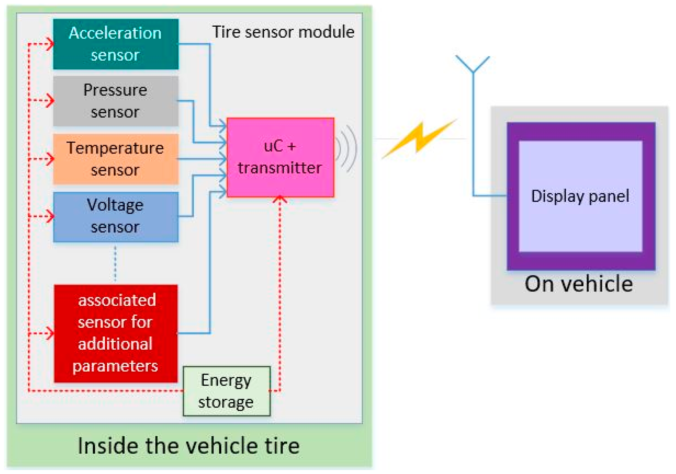
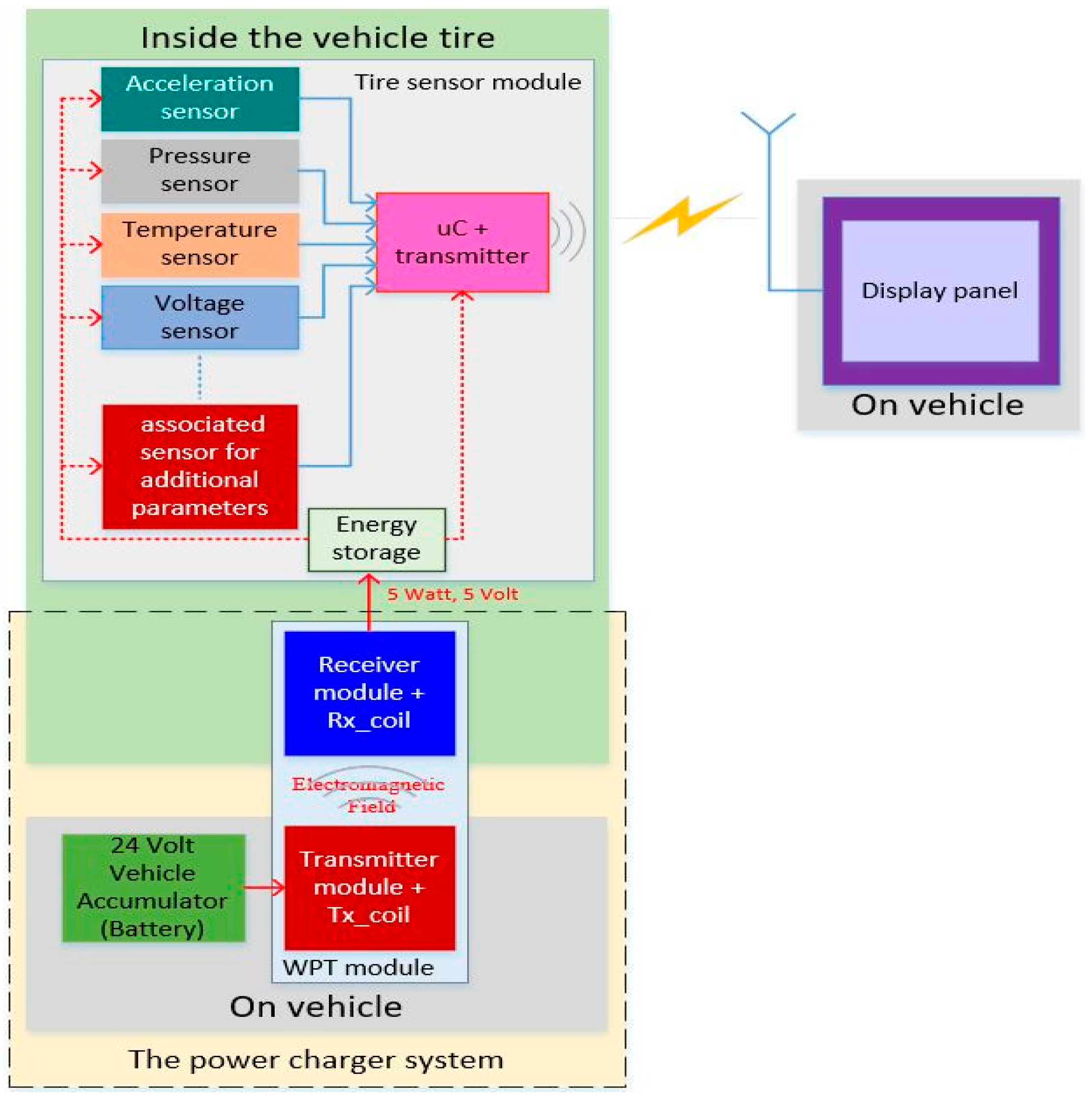
2.1. The Generic Intelligence-Tire System Architecture

In general, the intelligent-tire system generic architecture is depicted in Figure 1. It has four main units comprised the sensing unit, processing and communication unit, energy storage unit, and monitor terminal unit [27,28,29]. The sensing unit is comprised of different types of sensors including signal conditioning. The sensor type is associated with the parameters to be measured such as acceleration, pressure, temperature, voltage, load, torsion, etc. The processing and communication unit are single on chip (SoC) devices composed of microcontroller and wireless transmitter modules. The microcontroller will read and process the data from sensors, while the transmitter (Tx) module will transmit the measured tire parameters to monitor the terminal (user interface). The energy storage is the main power supply to maintain the energy supply for the sensing, processing, and communication units. The energy storage involves disposable/rechargeable battery or supercapacitor. The monitor terminal unit consists of a wireless receiver module which captures the data from the processing and communication unit, and a display panel which shows up on the tire parameters condition.
In the intelligent-tire system, the tire sensor module comprises the sensing, processing and communication, and energy storage unit which are embedded in the tire while the monitor terminal attached on the vehicle dashboard to provide information regarding the tire condition and characteristic to the vehicle driver and passenger.

2.2. The Proposed Tire Sensor Powering Strategy Concept
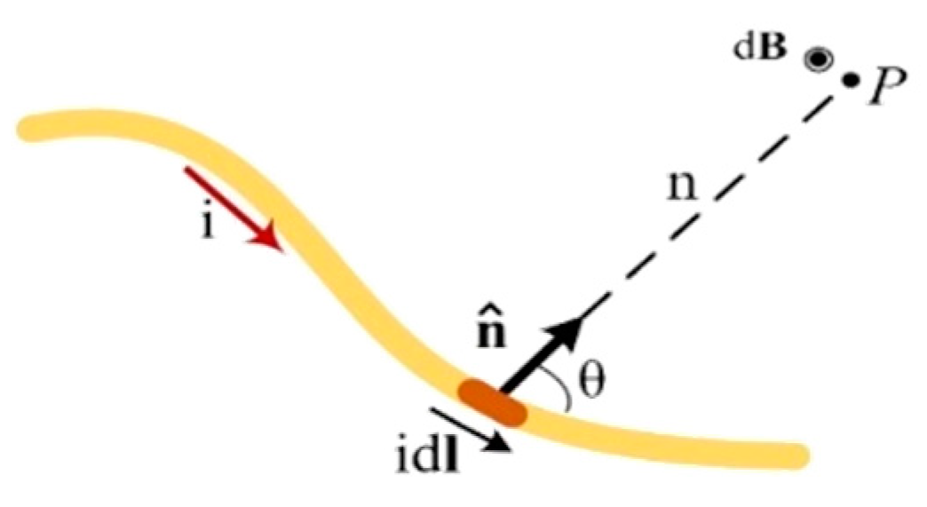
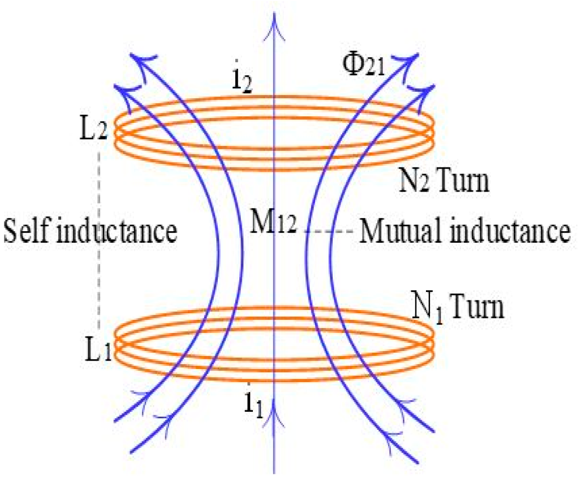
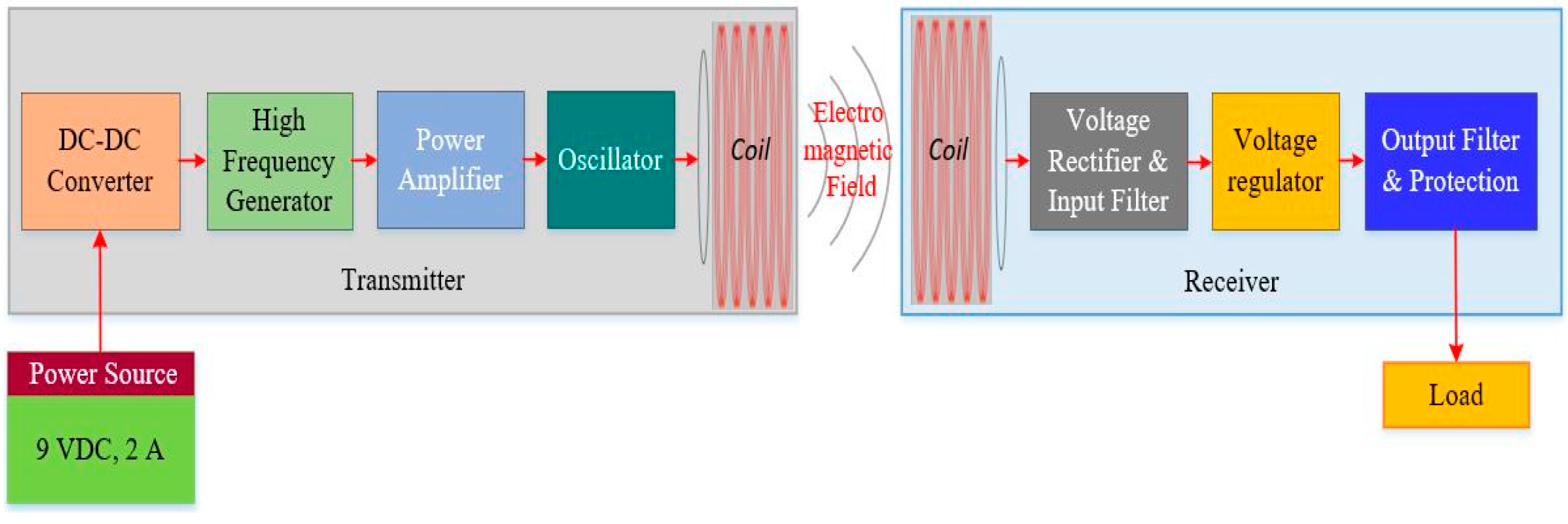
The tire sensor module is usually mounted inside the vehicle tire to monitor the tire condition. Since it is embedded in the tire, the tire sensor module becomes an autonomous and stand-alone device that has operating life depending on the power supply/energy storage capability. However, the power supply has a limited capacity for a long tire sensor operating period. Therefore, it needs to recharge to prolong the tire sensor life span.
A prospective and low-cost powering strategy is proposed to recharge the tire sensors energy storage/battery. The method adopts the electromagnetic induction principle. The WPT technology is utilized to recharge the tire sensor battery/energy storage embedded in the vehicle tire. The tire sensor battery/energy storage is possible to recharge through an air gap without replacing the battery or cable interconnection between the power source and the battery. This method is more convenient, robust, reliable, low-cost, safe, and environmentally friendly compared to other current tire sensor battery charger solution.
The proposed wireless power charger system configuration is presented in Figure 2. The transmitter and receiver coils location are shown in Figure 2a. The detailed proposed concept construction is described in Figure 2b. Several transmitter (Tx) coils are mounted on the vehicle inner fender liner. Those transmitter coils are utilized to emit an electromagnetic field generated by the transmitter module which is installed inside the vehicle. The transmitter modules exploit energy from the vehicle battery/accumulator to transfer power to the receiver modules. Several receiver (Rx) coils and modules are mounted on the vehicle tire inner wall where the receiver module output is coupled with the tire sensor. The receiver coils absorb the electromagnetic field which is emitted by transmitter coils and converted to the DC voltage by receiver module. This DC voltage is utilized to recharge the tire sensor battery/energy storage. This configuration is applied on all vehicle tires, both front and rear tires.

2.3. WPT Technology

In recent years, the wireless power transfer system has experienced increased growth as a re-emerging technology. This technology is based on electromagnetic field induction by adopting the mutual induction and resonance phenomena principle discovered by Michael Faraday who understood that electric energy can propagate by electromagnetic induction over the air [30]. The system’s main components normally consist of electromagnetic devices, power electronics, and a control system. The technology advance in electronic devices design and the increase in the overall WPT system make this technology be a good prospect to be applied in various wireless power applications from the low-power earphone to the high-power electric vehicles power charger. This technology can be applied in various applications where either a short or a continuous energy transmission is needed but the wire connection is unreachable, inconvenient, costly, high risk, undesirable, or impossible. The WPT is a technology that can transport power from one place to another which is otherwise impossible or impractical to reach.
The electromagnetic generation concept is shown in Figure 3, when a conductor, or as in this matter, a wire, is being flown with the electric current, an electromagnetic field will be generated around the wire. The sum of the electromagnetic field at a specific segment (dI) along a conductor at any point (P) is denoted as dB [31].
The electromagnetic field contribution is written using Biot–Savart law as follows:
d B   = µ o 4 π   id l × n ^ n 2
dB is the electromagnetic field contribution measured in Tesla (T), idl is the current segment measured in Ampere (A), the distance from the current source to the field point of P is denoted as n and measured in meter (m), n ^ is the corresponding unit vector, and lastly the permeability of free space is denoted as µo.
µ o = 4 π   ×   10 7   T .   m / A
The basic law of electromagnetism or the induction law of Faraday has clearly explained the electromagnetic induction phenomenon. The electromotive force (emf) is generated along the circuit if a magnetic flux that changes overtime is linked with a closed loop circuit, then an electromagnetic force or emf is induced along the circuit. The Faraday law of induction states that the magnitude of a magnetic flux Φ that passes through an area s is the sum of the surface integral to the magnetic field B. The magnetic flux can be expressed in an equation as follow [32]:
Φ = s B . d s
The change in magnetic flux rate is proportional to the emf induction or ε, this relation can be expressed in the below equation [32]:
ε = d Φ dt
Lenz’s law states that a negative sign in the Equation (5) indicates the direction of the induced current caused by emf is opposite to the electromagnetic field that produced it. By comparing (3)–(5), it can be written that,
emf     Φ     B     i
The electromagnetic inductive coupling topology is presented in Figure 4. Electromagnetic coupling between two independent coils can be defined as the interaction between two independent coils where each coil affects each other through the electromagnetic field produced by either one of them. In this case, the electromagnetic produced by one of the coils is coupled by the other coil. The first coil (coil1) has N1 windings that carry current i1, thus when the current flows into the coil, an electromagnetic field vector B1 is generated. The electromagnetic field generated by coil1 will also pass through coil2, although not entirely. The magnetic flux generated in coil2 due to the current i1 is denoted by Φ21. Thus, with the change of magnetic flux in the second coil due to the variation of i1 with time, an emf associated with the aforementioned flux will be induced [33]:
ε 21 = N 2 d Φ 21 dt = d dt coil   2 B 1 . d A 2
The current change of the time-varying in coil1 is equal to the rate of change of the magnetic flux Φ21 in coil2 [34,35], as expressed in the below equation:
N 2 d Φ 21 dt =   M 21 di 1 dt
In this case, beside the self-inductance (L) of each coil, another inductance also existed, known as the mutual inductance M21.

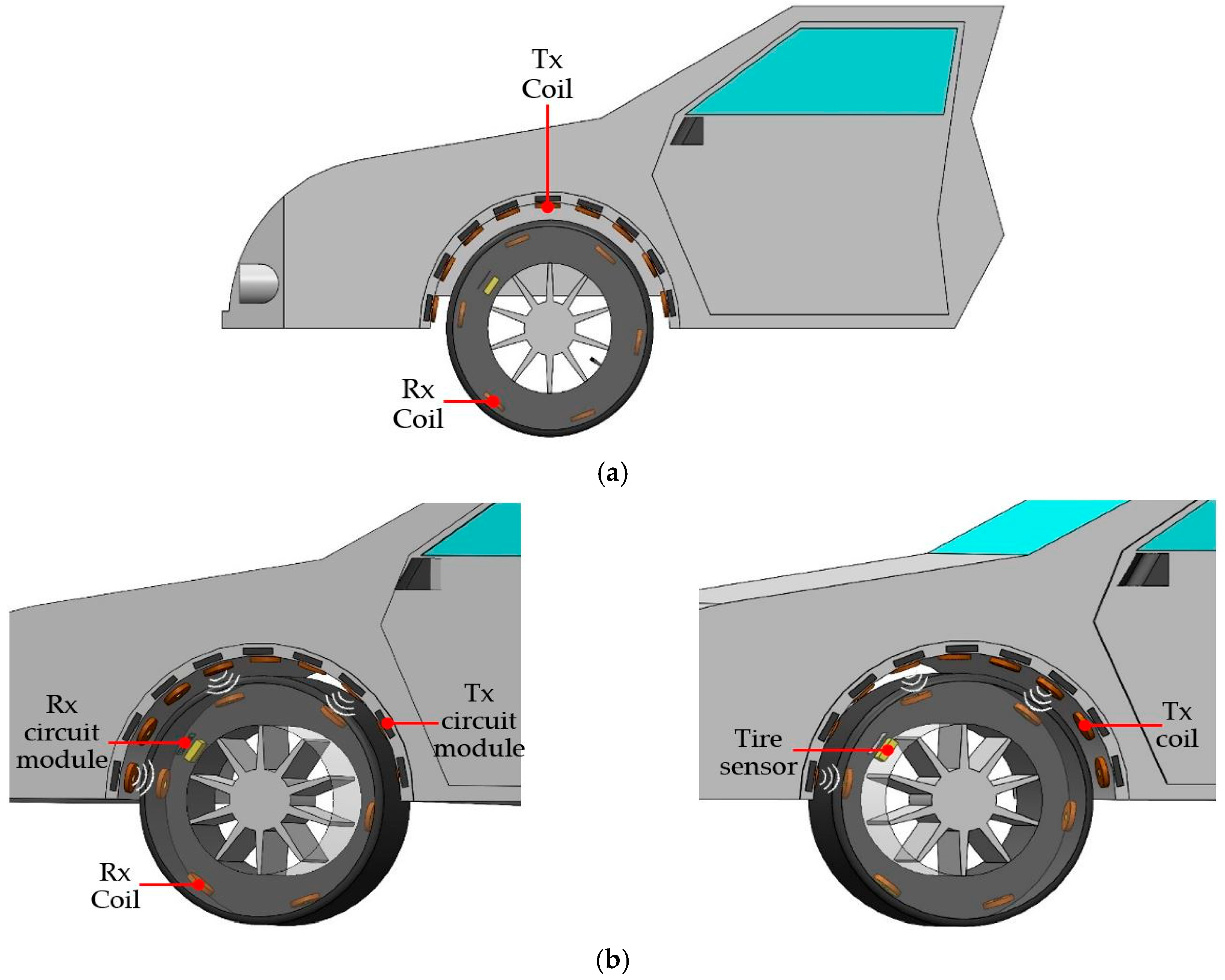
2.4. The Proposed Tire Sensor Powering Strategy Architecture

In the proposed system, the tire sensor components obtained the power from the main energy source that comes from a supercapacitor. The supercapacitor is utilized because it has a longer lifetime and high-power density in the Farad range [36,37]. The high-power density allows the supercapacitor to be charged/discharged quickly with also a large number of charge/discharge cycles. For long period operations, the supercapacitor is needed to be recharged to extend the life of the tire sensor using the proposed powering strategy as described in Section 2.2. The proposed powering strategy architecture is shown in Figure 5.
The main components of the proposed system are composed of the transmitter and receiver subsystems. The transmitter module generates a stable and high-power electromagnetic field through the transmitter coil to transfer DC voltage wirelessly. The DC voltage comes from the 24 V vehicle accumulator (battery). The generated electromagnetic fields are absorbed by the receiver coil and converted into DC voltage by the receiver module. The receiver module provides a stable DC voltage to recharge the tire sensor energy storage (supercapacitor).

2.5. The Proposed Powering Strategy Concept Verification Method

A WPT system was developed in [38] and applied in a power transfer experiment to verify the tire sensor powering strategy concept. The WPT system was designed based on induction electromagnetic coupling. The transmitter subsystem is composed of a DC-DC converter, high-frequency generator, power amplifier, oscillator, and a transmitter coil, while the receiver module consists of a receiver coil, voltage rectifier and input filter, voltage regulator, and output filter and protection component as shown in Figure 6. A 9 V, 2 A power supply is utilized as the energy source where the voltage is to be transferred to the receiver module, and the load represents the tire sensor energy storage (supercapacitor) to be recharged. The receiver module can provide a stable DC voltage of 5 V with maximum current up to 1 A to vehicle tire sensors.
The WPT system was implemented using the single-on chip (SoC) and surface-mounted device (SMD) of commercial off-the-shelf (COST) components that are available in the market. The implemented WPT system is shown in Figure 7. All transmitter and receiver electronic components were mounted on the top layer of the small printed circuit board (PCB), and circular flat spiral air core coil geometry was applied as transmitter and receiver coils. The coils were designed having inner and outer diameters of 25 mm and 47.89 mm. The circular flat spiral air core coil was chosen to be utilized in the proposed tire sensor power strategy because this geometry is suitable for mounting in a small space of the vehicle tire.
The main components characteristics of the WPT module are summarized in Table 1.
A simulator model is designed to be utilized in the proposed tire sensor powering strategy verification. The model is composed of a vehicle fender liner model, vehicle tire model, and WPT system module. The model layout is shown in Figure 8.
The model is described as follows. The transmitter module and coil are attached on the vehicle inner fender liner model. There are five transmitter modules and coils are configured as shown in the layout in Figure 8a. While, receiver modules and coils are attached to the tire model as shown in the configuration layout in Figure 8b. A load that is composed of a microcontroller module, a data logger module, and a voltage and current (power) sensor module is also attached to the vehicle tire model. The vehicle tire model coupled with a DC motor layout is shown in Figure 8c, and this construction is to demonstrate rotational motion. The vehicle inner fender liner and vehicle tire models are integrated to demonstrate the vehicle tire system as a configuration layout shown in Figure 8d.

3. Proposed Powering Strategy Verification

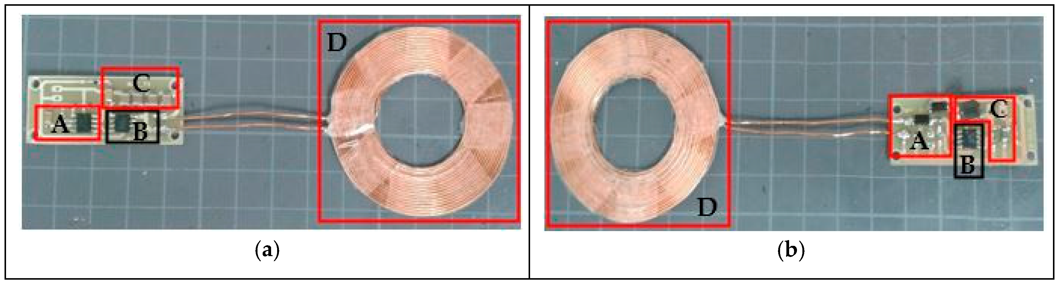
3.1. Model Configuration

In this experiment, the WPT module presented in Figure 5 is configured following the diagram in Figure 9. The receiver module output provides the voltage for a microcontroller module, a data logger module, and a voltage and current (power) sensor module. The voltage is transferred wirelessly from a 9 V, 2 A DC power supply to receiver module by the transmitter module. On the load side, a voltage and current (power) sensor is utilized to measure voltage and current consumption of the load (power sensor module, microcontroller module, and data logger module). The measured voltage and current data are recorded and stored in microSD memory by a data logger. This current and voltage data acquisition is controlled by a microcontroller module.
Furthermore, this power strategy configuration is applied to the vehicle tire system model as shown in Figure 10. The transmitter module and coil are mounted on the vehicle fender liner model with the distance between two coils is 2 cm. The five transmitter coils configuration forms a half circle as shown in Figure 10a. The receiver module and coil are mounted on the vehicle tire model as shown in Figure 10b,c. There are six receiver coils mounted on the outer perimeter of the vehicle tire model. The microcontroller, data logger, and voltage and current sensor are also mounted on the vehicle tire model.
The vehicle tire model is coupled with the DC motor to perform rotational motion as shown in Figure 10d. The overall vehicle tire system model including the WPT system module is shown in Figure 10e,f.

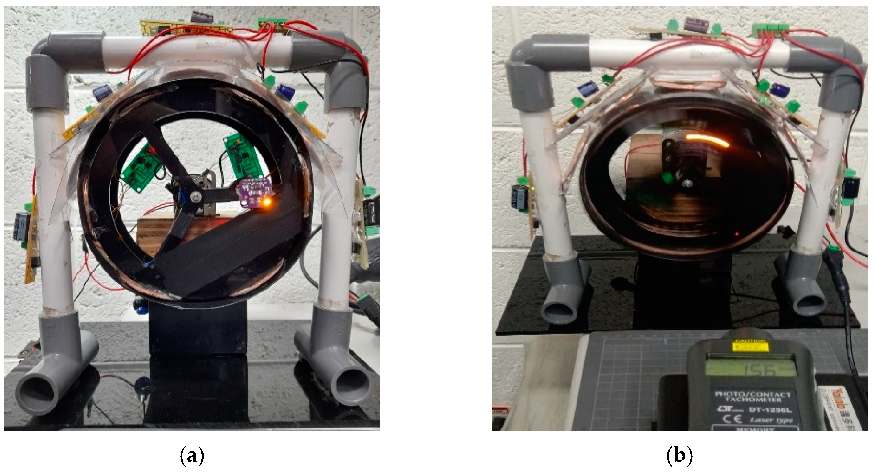
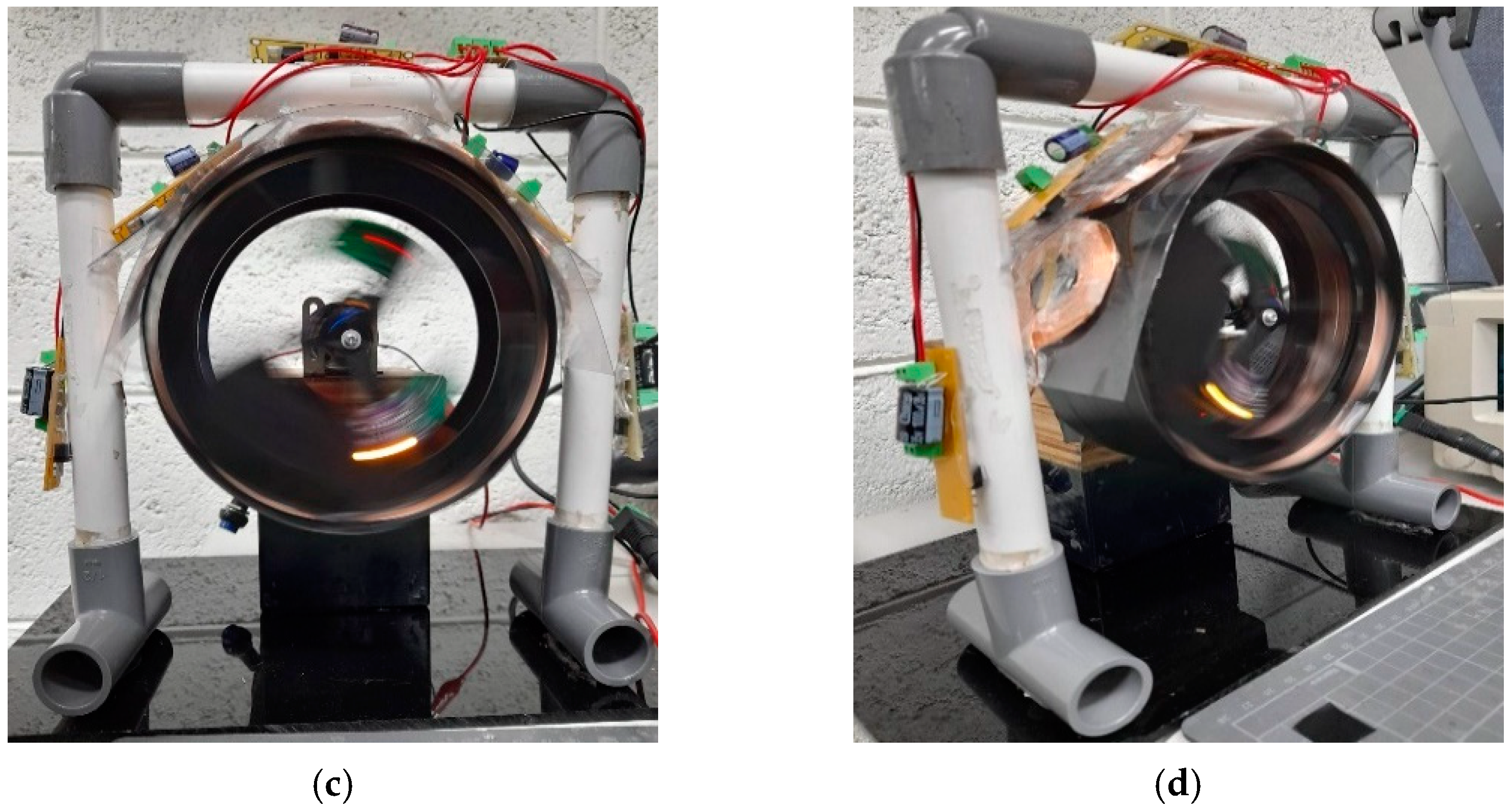
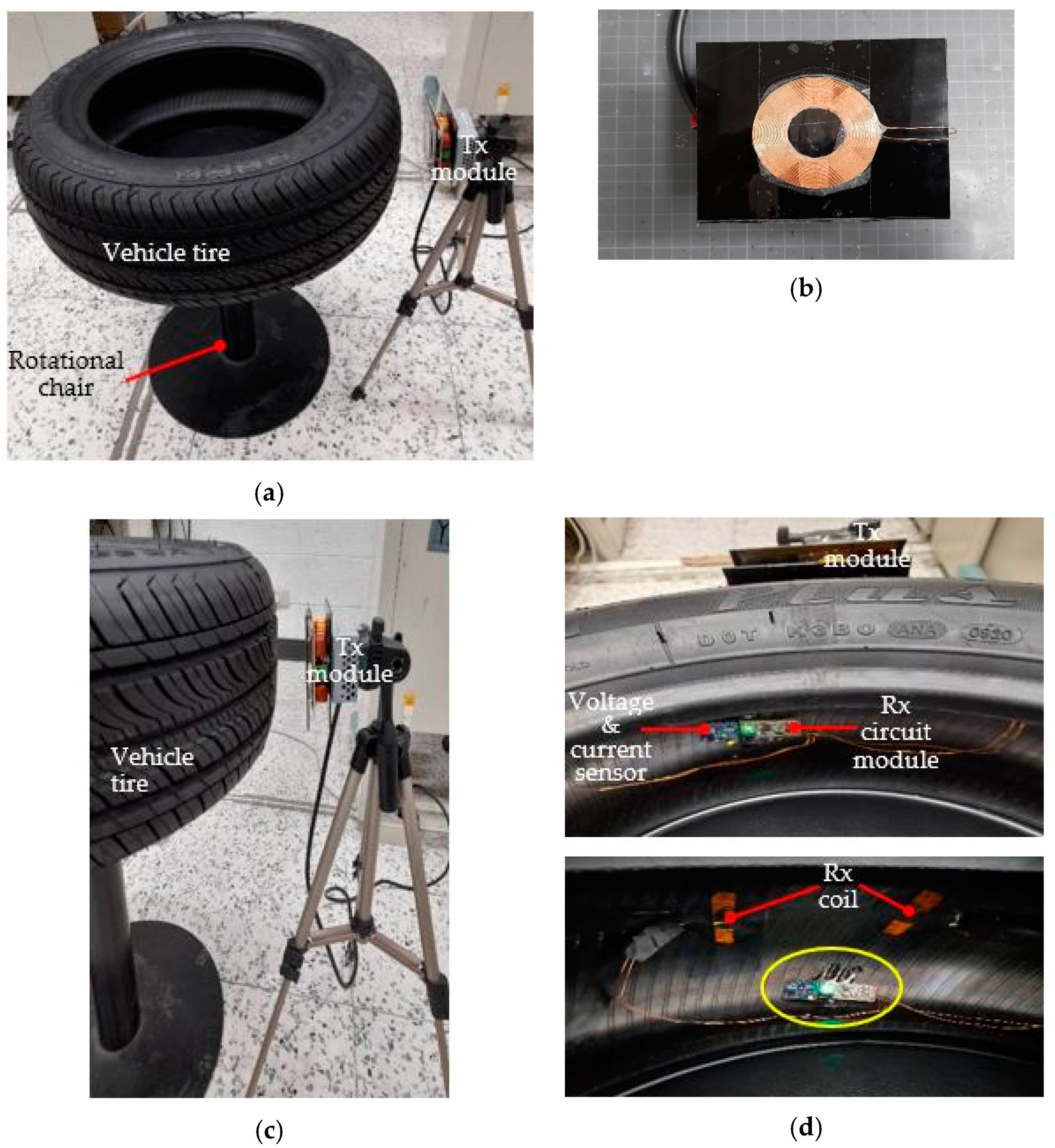
3.2. Method and Experiment

In the experiment, the vehicle tire model is rotated along the DC motor axis with different rotational speed following the experiment setup data as shown in Table 2, and the transmitter module is maintained to transfer the power wirelessly to the receiver module.
Figure 11 shows the verification process. A variable power supply was utilized to supply the DC motor with a regulated DC voltage. The regulated DC voltage drives the DC motor to achieve the rotation speed set-point following the experiment setup data in Table 1. The power sensor module, microcontroller module, and data logger module voltage and current consumption at 0 rpm were recorded for use as reference data for power transfer performance comparison with other vehicle tire model rotation speeds as shown in Figure 11a. Figure 11b shows a reference instrument (tachometer) was also used to measure concurrently the vehicle tire model rotation speed as a reference.
When the transmitter module transferred power to the receiver module in rotational motion of the vehicle tire model, the receiver module keeps providing voltage for the power sensor module, microcontroller module, and data logger module (voltage and current sensor indicator is turned on) as shown in Figure 11c,d. At the same time, the power sensor, microcontroller, and data logger modules performed an acquisition data of their voltage and current consumption.

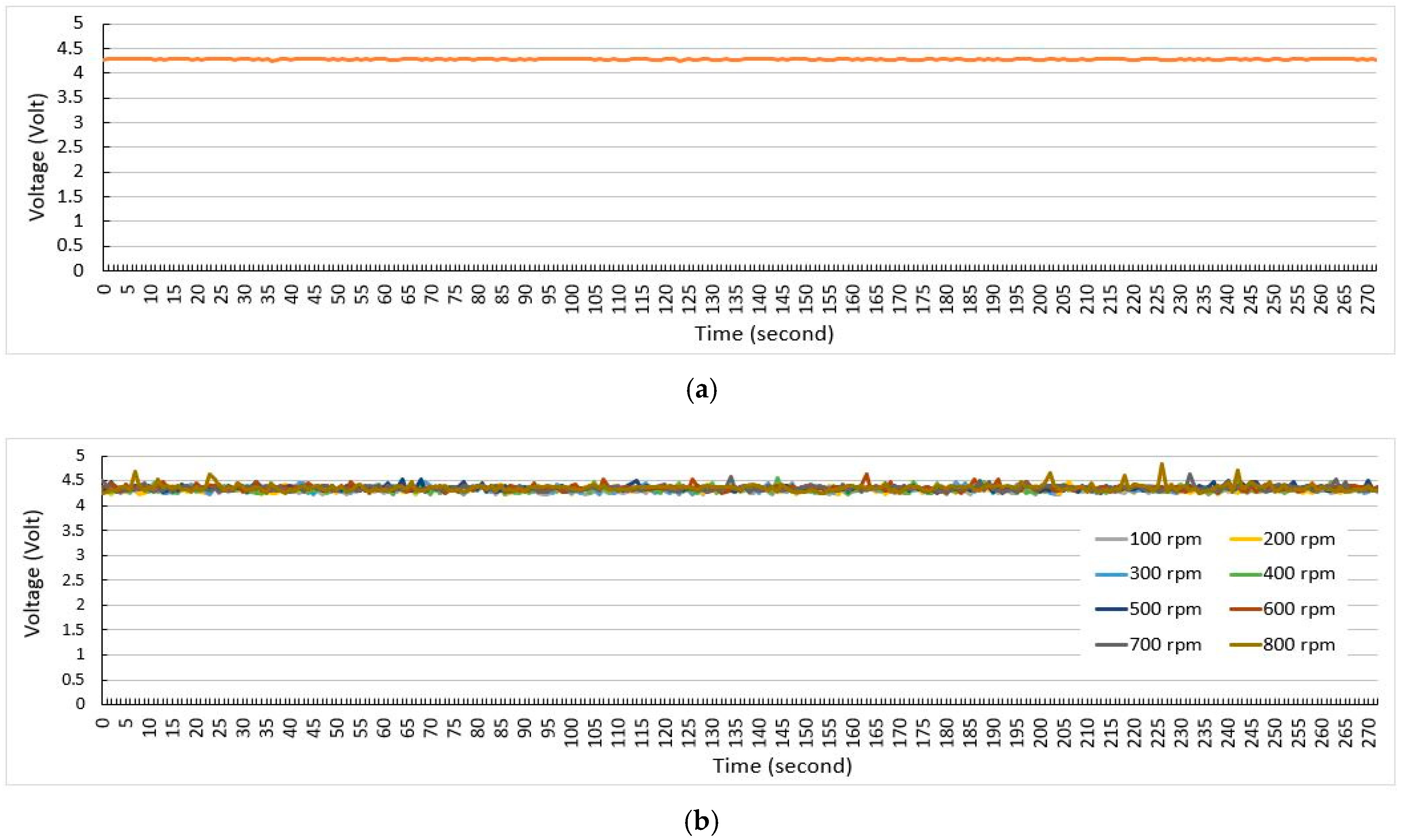
4. Result and Discussion

The load voltage and current consumption (the power sensor module, microcontroller module, and data logger module) measurement results are shown in Figure 12 and Figure 13. The average voltage consumption at 0 rpm is around 4.28 V as shown in Figure 12a. The voltage consumption of the load in different rotation motion speed of the vehicle tire model shows a relative constant trend close to the average voltage consumption at 0 rpm as shown in Figure 12b.
The experiment results revealed that the average load voltage consumption in rotation motion of the vehicle tire model is around 4.3 V as presented in Table 3.
Meanwhile, the current load consumption shows the same trend compared with the voltage consumption. The average current consumption at 0 rpm is around 20.71 mA as shown in Figure 13a, and the current consumption of the load in different rotation motion speed of the vehicle tire model shows the trend close to the average current consumption at 0 rpm as shown in Figure 13b.
The average current consumption of the load in rotation motion of the vehicle tire model is shown in Table 4.
The experiment results show that the receiver module still can provide output voltage and current relatively constant although the receiver module was moving in rotation motion as shown in the experiment process and results in Figure 11, Figure 12 and Figure 13. Although the rotation motion of the receiver module also causes a small ripple on the voltage and current consumption trend of the load as shown in Figure 12b and Figure 13b, however this voltage and current ripple is close to the voltage and current consumption of the load on the receiver module rotation motion at 0 rpm. The voltage and current ripple occurred due to the effect of moving the coil in the uniform electromagnetic field. In this experiment, the receiver coil was also moving across the uniform electromagnetic fields emitted by the transmitter coil in the coil center axis direction. This rotation coil arises which it called the emf motion as reported by Faraday in his experiment [32]. The experiment results also verify that the proposed powering strategy can be applied to recharge the battery/energy storage of the tire sensor while considering the tire sensor power requirement.
Typically, the tire sensor module power consumption has been lower since the technological advance in low-power electronic component and sensor technology is applied in electronic device design. The tire sensor also can be programmed to only work in active mode periodically for sensing, processing, and communication in order to reduce power consumption as shown in the typical tire sensor power consumption timing diagram in Figure 14.
In the example of the tire sensor current consumption diagram as shown in Figure 15, the maximum current consumption of the tire sensor is only 10 mA, and the total current consumption for sensing, processing, and transmit RF is estimated at around 40 mA. Considering this tire sensor power requirement example and the verification experiment results presented above, the proposed powering strategy is feasible to be implemented in the tire sensor battery/energy storage recharger method.
Figure 15 shows the wireless power receiver module and power (voltage and current) sensor installation mounted inside the inner wall of a vehicle tire.
The installation demonstrates the proposed powering strategy in a real-life application with compact, small size, and light system. The proposed powering strategy occupies a small space inside of a vehicle tire, therefore, it is safe, and does not affect the performance of the vehicle tire while the vehicle is in motion.
In order to demonstrate power transfer function in a real application, a simple preliminary test was conducted as presented in Figure 16. A test configuration is shown in Figure 16a. A vehicle tire included with the wireless power receiver module and power sensor mounted inside the tire (Figure 15) is placed on a rotational chair. This setup emulates a vehicle tire rolling as in a real vehicle tire system. A Tx wireless power module (Figure 16b) placed on a tripod camera at 8 cm away from the vehicle tire is shown in Figure 16c.
In the preliminary test, the vehicle tire rotated on a rotational chair. When the Rx coil was mounted inside the vehicle tire wall face with the Tx coil, the indicator lamps of the receiver circuit module and power sensor were turn on as shown in Figure 16d. This preliminary test revealed that the Tx module was able to transfer power to the receiver circuit module and power sensor.

5. Conclusions

This paper presented a prospective powering strategy for tire sensors. The WPT technology is proposed to transfer power from the vehicle accumulator to the battery of the tire sensors that are mounted inside a vehicle tire. The proposed strategy was designed considering tire sensor location and power requirement in an intelligent-tire system. The verification experiment and preliminary test show that the WPT technology applied in the proposed strategy is feasible to implement in the tire sensor powering strategy. The verification experiment and preliminary test results reveal that the developed WPT device for the proposed powering strategy can transfer the power constantly, although the tire model is in rolling condition. Moreover, the output power of the developed WPT device is sufficient to recharge the battery/energy storage of the tire sensors in the real intelligent-tire system to extend the tire sensor lifetime. The magnetic resonance method of WPT technology will be developed to extend the transmission distance and to improve alignment between TX and Rx coils in further research work.

Author Contributions

Conceptualization, Y.-D.K. and C.B.D.K.; methodology, Y.-D.K. and C.B.D.K.; formal analysis, C.B.D.K. and M.-F.S.; investigation, M.-F.S., C.A., and A.F.P.; supervision, Y.-D.K.; resources, Y.-D.K.; writing-original draft preparation, C.A. and A.F.P.; writing-review and editing, C.B.D.K. and Y.-D.K. All authors have read and agreed to the published version of the manuscript.

Funding

This research was supported by the Ministry of Science and Technology Taiwan (MOST: 109-2622-E-167-014-CC2).

Data Availability Statement

The data presented in this study are available on the request from the corresponding author.

Acknowledgments

The authors thank the Ministry of Science and Technology of Taiwan.

Conflicts of Interest

The authors declare no conflict of interest.

References

  1. Schulze, T.; Müller, B.; Meyer, G. Advanced Microsystems for Automotive Applications 2016: Smart Systems for the Automobile of the Future; Springer: Berlin/Heidelberg, Germany; New York, NY, USA, 2016; ISBN 9783319447650. [Google Scholar]
  2. Ray, S.; Chen, W.; Bhadra, J.; Al Faruque, M.A. Extensibility in Automotive Security: Current Practice and Challenges: Invited. In Proceedings of the 54th Annual Design Automation Conference 2017, Austin, TX, USA, 18–22 June 2017; ACM: New York, NY, USA, 2017; pp. 1–6. [Google Scholar]
  3. Peden, M.M. World Report on Road Traffic Injury Prevention; World Health Organization: Geneva, Switzerland, 2004; ISBN 9789241562607. [Google Scholar]
  4. Keck, M. A New Approach of a Piezoelectric Vibration-Based Power Generator to Supply next Generation Tire Sensor Systems. In Proceedings of the 2007 IEEE Sensors, Atlanta, GA, USA, 28–32 October 2007; pp. 1299–1302. [Google Scholar] [CrossRef]
  5. Chen, Y.-Y.; Pan, H.-W. A Piezoelectric Vibration Energy Harvester for Tire Pressure Monitoring Systems. In Proceedings of the Symposium on Ultrasonic Electronics, Kyoto, Japan, 8–10 November 2011; Volume 32, pp. 321–322. [Google Scholar]
  6. Zheng, Q.; Tu, H.; Agee, A.; Xu, Y. Vibration Energy Harvesting Device Based on Asymmetric Air-Spaced Cantilevers for Tire Pressure Monitoring System. In Proceedings of the the Power MEMS 2009, Washington, DC, USA, 1–4 December 2009; pp. 403–406. [Google Scholar]
  7. Hatipoglu, G.; Urey, H. FR4-Based Electromagnetic Energy Harvester for Wireless Tyre Sensor Nodes. Procedia Chem. 2009, 1, 1211–1214. [Google Scholar] [CrossRef]
  8. Manla, G.; White, N.M.; Tudor, J. Harvesting Energy from Vehicle Wheels. In Proceedings of the Solid-State Sensors, Actuators and Microsystems Conference, Denver, CO, USA, 21–25 June 2009; pp. 1389–1392. [Google Scholar]
  9. Tang, Q.C.; Xia, X.Y.; Li, X.X. Non-Contact Frequency-up-Conversion Energy Harvester for Durable & Broad-Band Automotive TPMS Application. In Proceedings of the 2012 IEEE 25th International Conference on Micro Electro Mechanical Systems (MEMS), Paris, France, 29 January–2 February 2012; pp. 1273–1276. [Google Scholar] [CrossRef]
  10. Tornincasa, S.; Repetto, M.; Bonisoli, E.; Di Monaco, F. Energy Harvester for Vehicle Tires: Nonlinear Dynamics and Experimental Outcomes. J. Intell. Mater. Syst. Struct. 2012, 23, 3–13. [Google Scholar] [CrossRef]
  11. Frey, A.; Seidel, J.; Schreiter, M.; Kuehne, I. Piezoelectric MEMS Energy Harvesting Module Based on Non-Resonant Excitation. In Proceedings of the 2011 16th International Solid-State Sensors, Actuators and Microsystems Conference, Beijing, China, 5–9 June 2011; pp. 683–686. [Google Scholar] [CrossRef]
  12. Hu, Y.; Xu, C.; Zhang, Y.; Lin, L.; Snyder, R.L.; Wang, Z.L. A Nanogenerator for Energy Harvesting from a Rotating Tire and Its Application as a Self-Powered Pressure/Speed Sensor. Adv. Mater. 2011, 23, 4068–4071. [Google Scholar] [CrossRef]
  13. Gu, L.; Livermore, C. Pendulum-Driven Passive Self-Tuning Energy Harvester for Rotating Applications. In Proceedings of the PowerMEMS workshop, Leuven, Belgium, 30 November–3 December 2010. [Google Scholar]
  14. Pinna, L. Vibration-Based Energy Scavenging for Power Autonomous Wireless Sensor Systems. Ph.D. Thesis, University of Genoa, Genoa, Italy, February 2010; p. 141. [Google Scholar]
  15. Corti, F.; Reatti, A.; Nepote, A.; Pugi, L.; Pierini, M.; Paolucci, L.; Grasso, F.; Grasso, E.; Nienhause, M. A Secondary-Side Controlled Electric Vehicle Wireless Charger. Energies 2020, 13, 6527. [Google Scholar] [CrossRef]
  16. Wu, H.H.; Gilchrist, A.; Sealy, K.D.; Bronson, D. A High Efficiency 5 kW Inductive Charger for EVs Using Dual Side Control. IEEE Trans. Ind. Inform. 2012, 8, 585–595. [Google Scholar] [CrossRef] [Green Version]
  17. Zheng, C.; Lai, J.-S.; Chen, R.; Faraci, W.E.; Zahid, Z.U.; Gu, B.; Zhang, L.; Lisi, G.; Anderson, D. High-Efficiency Contactless Power Transfer System for Electric Vehicle Battery Charging Application. IEEE J. Emerg. Sel. Top. Power Electron. 2015, 3, 65–74. [Google Scholar] [CrossRef]
  18. Corti, F.; Grasso, F.; Paolucci, L.; Pugi, L.; Luchetti, L. Circular Coil for EV Wireless Charging Design and Optimization Considering Ferrite Saturation. In Proceedings of the 2019 IEEE 5th International forum on Research and Technology for Society and Industry (RTSI), Florence, Italy, 9–12 September 2019. [Google Scholar]
  19. Choi, S.Y.; Gu, B.W.; Jeong, S.Y.; Rim, C.T. Advances in Wireless Power Transfer Sys-tems for Roadway-Powered Electric Vehicles. IEEE J. Emerg. Sel. Top. Power Electron. 2015, 3, 18–36. [Google Scholar] [CrossRef]
  20. Throngnumchai, K.; Hanamura, A.; Naruse, Y.; Takeda, K. Design and evaluation of a wireless power transfer system with road embedded transmitter coils for dynamic charging of electric vehicles. In Proceedings of the 2013 World Electric Vehicle Symposium and Exhibition (EVS27), Barcelona, Spain, 17–20 November 2013; pp. 1–10. [Google Scholar] [CrossRef] [Green Version]
  21. Rozman, M.; Ikpehai, A.; Adebisi, B.; Rabie, K.; Gacanin, H.; Ji, H.; Fernando, M. Smart Wireless Power Transmission System for Autonomous EV Charging. IEEE Access 2019, 7, 112240–112248. [Google Scholar] [CrossRef]
  22. Chittoor, P.K.; Chokkalingam, B.; Mihet-Popa, L. A Review on UAV Wireless Charging: Fundamentals, Applications, Charging Techniques and Standards. IEEE Access 2021, 9, 69235–69266. [Google Scholar] [CrossRef]
  23. Rohan, A.; Rabah, M.; Talha, M.; Kim, S.-H. Development of intelligent drone battery charging system based on wireless power transmission using hill climbing algorithm. Appl. Syst. Innov. 2018, 1, 44. [Google Scholar] [CrossRef] [Green Version]
  24. Junaid, A.B.; Lee, Y.; Kim, Y. Design and implementation of autonomous wireless charging station for rotary-wing UAVs. Aerosp. Sci. Technol. 2016, 54, 253–266. [Google Scholar] [CrossRef]
  25. Yan, Y.; Shi, W.; Zhang, X. Design of UAV wireless power transmission system based on coupling coil structure optimization. EURASIP J. Wireless Commun. Netw. 2020, 1, 1–13. [Google Scholar] [CrossRef]
  26. Campi, T.; Cruciani, S.; Feliziani, M. Wireless power transfer technology applied to an autonomous electric UAV with a small secondary coil. Energies 2018, 11, 352. [Google Scholar] [CrossRef] [Green Version]
  27. APPOLO. Intelligent Tyre Systems-State of the Art and Potential Technologies; Technical Research Centre of Finland (VTT): Espoo, Finland, 2003. [Google Scholar]
  28. Singh, K.B.; Arat, M.A.; Taheri, S. Development of a Smart Tire System and Its Use in Improving the Performance of a Collision Mitigation Braking System. In Proceedings of the Volume 11: Transportation Systems, Houston, TX, USA, 9–15 November 2012; pp. 77–87. [Google Scholar]
  29. Jo, H.Y.; Yeom, M.; Lee, J.; Park, K.; Oh, J. Development of Intelligent Tire System; SAE Technical Paper; SAE: Warrendale, PA, USA, 8 April 2013. [Google Scholar]
  30. Amar, A.; Kouki, A.; Cao, H. Power Approaches for Implantable Medical Devices. Sensors 2015, 15, 28889–28914. [Google Scholar] [CrossRef] [PubMed]
  31. Luo, W.-J.; Kuncoro, C.B.D.; Pratikto; Kuan, Y.-D. Single-Layer Transmitter Array Coil Pattern Evaluation toward a Uniform Vertical Magnetic Field Distribution. Energies 2019, 12, 4157. [Google Scholar] [CrossRef] [Green Version]
  32. Hayt, W.H.; Buck, J.A. Engineering Electromagnetics, 8th ed.; McGraw-Hill: New York, NY, USA, 2012; ISBN 9780073380667. [Google Scholar]
  33. Wei, X.C.; Li, E.P.; Guan, Y.L.; Chong, Y.H. Simulation and Experimental Comparison of Different Coupling Mechanisms for the Wireless Electricity Transfer. J. Electromagn. Waves Appl. 2009, 23, 925–934. [Google Scholar] [CrossRef]
  34. Mendes Duarte, R.; Klaric Felic, G. Analysis of the Coupling Coefficient in Inductive Energy Transfer Systems. Act. Passiv. Electron. Compon. 2014, 2014, 1–6. [Google Scholar] [CrossRef] [Green Version]
  35. Karalis, A.; Joannopoulos, J.D.; Soljačić, M. Efficient Wireless Non-Radiative Mid-Range Energy Transfer. Ann. Phys. 2008, 323, 34–48. [Google Scholar] [CrossRef] [Green Version]
  36. Diab, Y.; Venet, P.; Gualous, H.; Rojat, G. Self-Discharge Characterization and Modeling of Electrochemical Capacitor Used for Power Electronics Applications. IEEE Trans. Power Electron. 2009, 24, 510–517. [Google Scholar] [CrossRef]
  37. Simjee, F.I.; Chou, P.H. Efficient Charging of Supercapacitors for Extended Lifetime of Wireless Sensor Nodes. IEEE Trans. Power Electron. 2008, 23, 1526–1536. [Google Scholar] [CrossRef]
  38. Luo, W.-J.; Kuncoro, C.B.D.; Kuan, Y.-D. Wireless Power Hanger Pad for Portable Wireless Audio Device Power Charger Application. Energies 2020, 13, 419. [Google Scholar] [CrossRef] [Green Version]
Figure 1. The typical intelligence-tire system architecture.
Electronics 10 01424 g001
Figure 2. Tire sensor power charger proposed configuration: (a) Tx and Rx location, (b) Tx dan Rx modules detail location.
Electronics 10 01424 g002
Figure 3. The electromagnetic field dB at point P.
Electronics 10 01424 g003
Figure 4. The topology of typical electromagnetic inductive coupling.
Electronics 10 01424 g004
Figure 5. The tire sensor powering architecture.
Electronics 10 01424 g005
Figure 6. The wireless power transfer diagram for tire sensor powering strategy.
Electronics 10 01424 g006
Figure 7. The implemented wireless power transfer modules: (a) transmitter (part A is a DC-DC converter and a high-frequency generator, part B is power amplifier, part C is an oscillator, part D is transmitter coil), (b) receiver (part A is a voltage rectifier and input filter, part B is a voltage regulator, part C is an output filter and protection, part D is a receiver coil).
Electronics 10 01424 g007
Figure 8. A tire sensor powering strategy model layout: (a) vehicle fender liner model including transmitter module and coil, (b) vehicle tire model including receiver module and coil, (c) vehicle tire model couples with DC motor, (d) overall integrated model.
Electronics 10 01424 g008
Figure 9. The power charger setup diagram for tire sensor power charging experiment.
Electronics 10 01424 g009
Figure 10. The experiment setup: (a) the vehicle’s inner fender liner model, (b) the vehicle tire model front view, (c) the vehicle tire model side view, (d) the vehicle tire model coupled with DC motor, (e) the overall vehicle tire system model front view, (f) the overall vehicle tire system model side view.
Electronics 10 01424 g010
Figure 11. The experiment: (a) power transfer at 0 rpm, (b) rotation motion speed measurement, (c) power transfer in rotation motion (front view), (d) power transfer in rotation motion (side view).
Electronics 10 01424 g011aElectronics 10 01424 g011b
Figure 12. The voltage consumption data trend: (a) at 0 rpm, (b) at different rotation speed in range of 100 to 800 rpm.
Electronics 10 01424 g012
Figure 13. The current consumption data trend: (a) at 0 rpm, (b) at different rotation speed in range of 100 to 800 rpm.
Electronics 10 01424 g013
Figure 14. The current consumption timing diagram of the typical tire sensor.
Electronics 10 01424 g014
Figure 15. The wireless power receiver module and power sensor installation.
Electronics 10 01424 g015
Figure 16. The functionality demonstration: (a) test configuration, (b) transmitter module, (c) transmitter module setup, (d) indication of receiver module and power sensor.
Electronics 10 01424 g016
Table 1. WPT module parameters.
ParameterDescriptionValue
Coil geometrycircular flat spiral air core coil-
Transmission method
Rx module topology
electromagnetic induction
full-wave rectifier
-
foperating frequency110 kHz
DiTxinner diameter of Tx coil25 mm
DoTxouter diameter of Tx coil47.89 mm
DiRxinner diameter of Rx coil25 mm
DoRx
LTx
outer diameter of Rx coil
Tx coil inductance
47.89 mm
13.7 µH
LRx
d
ɳ
Rx coil inductance
maximum transmission distance
peak efficiency
13.7 µH
2 cm
70%
W
V
I
maximum power delivery
Rx module output voltage
Rx module maximum output current
5 W
5 V
1 A
Table 2. The experiment setup data.
NoRotation Speed
(rpm)
Time Duration
(s)
Time Step
(s)
102801
21002801
32002801
43002801
54002801
65002801
76002801
87002801
98002801
Table 3. The average voltage consumption.
NoRotation Speed
(rpm)
Average Voltage
(V)
11004.32
22004.33
33004.33
44004.33
55004.35
66004.35
77004.35
88004.36
Table 4. The average current consumption.
NoRotation Speed
(rpm)
Average Current
(mA)
110021.03
220021.08
330021.12
440021.15
550021.04
660021.19
770021.18
880021.36
Publisher’s Note: MDPI stays neutral with regard to jurisdictional claims in published maps and institutional affiliations.

